EP3611553A1 - Light deflecting device - Google Patents
Light deflecting device Download PDFInfo
- Publication number
- EP3611553A1 EP3611553A1 EP19191680.8A EP19191680A EP3611553A1 EP 3611553 A1 EP3611553 A1 EP 3611553A1 EP 19191680 A EP19191680 A EP 19191680A EP 3611553 A1 EP3611553 A1 EP 3611553A1
- Authority
- EP
- European Patent Office
- Prior art keywords
- opening
- rotary polyhedron
- light beam
- cover
- polygon mirror
- Prior art date
- Legal status (The legal status is an assumption and is not a legal conclusion. Google has not performed a legal analysis and makes no representation as to the accuracy of the status listed.)
- Granted
Links
- 230000002093 peripheral effect Effects 0.000 claims abstract description 57
- 238000011144 upstream manufacturing Methods 0.000 claims description 9
- 239000004094 surface-active agent Substances 0.000 claims 1
- 230000003287 optical effect Effects 0.000 description 49
- 238000010586 diagram Methods 0.000 description 6
- 238000000034 method Methods 0.000 description 6
- 230000002265 prevention Effects 0.000 description 6
- 230000004075 alteration Effects 0.000 description 5
- 230000000694 effects Effects 0.000 description 4
- 238000007639 printing Methods 0.000 description 3
- 238000004140 cleaning Methods 0.000 description 2
- 230000006866 deterioration Effects 0.000 description 2
- 238000002474 experimental method Methods 0.000 description 2
- 230000002194 synthesizing effect Effects 0.000 description 2
- 230000015572 biosynthetic process Effects 0.000 description 1
- 238000007664 blowing Methods 0.000 description 1
- 239000003990 capacitor Substances 0.000 description 1
- 239000003086 colorant Substances 0.000 description 1
- 230000000052 comparative effect Effects 0.000 description 1
- 230000007423 decrease Effects 0.000 description 1
- 239000000428 dust Substances 0.000 description 1
- 238000005516 engineering process Methods 0.000 description 1
Images


Classifications
-
- G—PHYSICS
- G02—OPTICS
- G02B—OPTICAL ELEMENTS, SYSTEMS OR APPARATUS
- G02B26/00—Optical devices or arrangements for the control of light using movable or deformable optical elements
- G02B26/08—Optical devices or arrangements for the control of light using movable or deformable optical elements for controlling the direction of light
- G02B26/10—Scanning systems
- G02B26/12—Scanning systems using multifaceted mirrors
-
- G—PHYSICS
- G02—OPTICS
- G02B—OPTICAL ELEMENTS, SYSTEMS OR APPARATUS
- G02B26/00—Optical devices or arrangements for the control of light using movable or deformable optical elements
- G02B26/08—Optical devices or arrangements for the control of light using movable or deformable optical elements for controlling the direction of light
- G02B26/10—Scanning systems
- G02B26/105—Scanning systems with one or more pivoting mirrors or galvano-mirrors
-
- G—PHYSICS
- G02—OPTICS
- G02B—OPTICAL ELEMENTS, SYSTEMS OR APPARATUS
- G02B26/00—Optical devices or arrangements for the control of light using movable or deformable optical elements
- G02B26/08—Optical devices or arrangements for the control of light using movable or deformable optical elements for controlling the direction of light
- G02B26/10—Scanning systems
- G02B26/12—Scanning systems using multifaceted mirrors
- G02B26/121—Mechanical drive devices for polygonal mirrors
-
- G—PHYSICS
- G02—OPTICS
- G02B—OPTICAL ELEMENTS, SYSTEMS OR APPARATUS
- G02B26/00—Optical devices or arrangements for the control of light using movable or deformable optical elements
- G02B26/08—Optical devices or arrangements for the control of light using movable or deformable optical elements for controlling the direction of light
- G02B26/10—Scanning systems
- G02B26/12—Scanning systems using multifaceted mirrors
- G02B26/123—Multibeam scanners, e.g. using multiple light sources or beam splitters
-
- G—PHYSICS
- G02—OPTICS
- G02B—OPTICAL ELEMENTS, SYSTEMS OR APPARATUS
- G02B26/00—Optical devices or arrangements for the control of light using movable or deformable optical elements
- G02B26/08—Optical devices or arrangements for the control of light using movable or deformable optical elements for controlling the direction of light
- G02B26/10—Scanning systems
- G02B26/12—Scanning systems using multifaceted mirrors
- G02B26/127—Adaptive control of the scanning light beam, e.g. using the feedback from one or more detectors
-
- G—PHYSICS
- G02—OPTICS
- G02B—OPTICAL ELEMENTS, SYSTEMS OR APPARATUS
- G02B7/00—Mountings, adjusting means, or light-tight connections, for optical elements
- G02B7/18—Mountings, adjusting means, or light-tight connections, for optical elements for prisms; for mirrors
- G02B7/182—Mountings, adjusting means, or light-tight connections, for optical elements for prisms; for mirrors for mirrors
- G02B7/1821—Mountings, adjusting means, or light-tight connections, for optical elements for prisms; for mirrors for mirrors for rotating or oscillating mirrors
-
- G—PHYSICS
- G03—PHOTOGRAPHY; CINEMATOGRAPHY; ANALOGOUS TECHNIQUES USING WAVES OTHER THAN OPTICAL WAVES; ELECTROGRAPHY; HOLOGRAPHY
- G03G—ELECTROGRAPHY; ELECTROPHOTOGRAPHY; MAGNETOGRAPHY
- G03G15/00—Apparatus for electrographic processes using a charge pattern
- G03G15/04—Apparatus for electrographic processes using a charge pattern for exposing, i.e. imagewise exposure by optically projecting the original image on a photoconductive recording material
- G03G15/04036—Details of illuminating systems, e.g. lamps, reflectors
Definitions
- the technology of the present disclosure relates to a light deflecting device.
- a light deflecting device in an image forming apparatus, for example.
- the light deflecting device includes a rotary polyhedron and a cover that covers the rotary polyhedron, and the cover is formed with an opening facing a peripheral surface of the rotary polyhedron.
- Light emitted from a light source is irradiated to the peripheral surface of the rotary polyhedron through the opening of the cover, and the rotary polyhedron allows the light to be deflected and scanned with respect to an image carrying member as an object to be irradiated through the opening while rotating about an axial center thereof. In this way, an electrostatic latent image is formed on a surface of the image carrying member.
- the cover of this type of light deflecting device is a non-sealed type cover formed with the opening, noise generated by the rotation of the rotary polyhedron leaks out of the cover from the opening.
- the noise is reduced by forming the opening as small as possible.
- a light deflecting device of an aspect of the present disclosure includes a rotary polyhedron and a cover that covers the rotary polyhedron.
- the cover includes an opening facing a peripheral surface of the rotary polyhedron. Light beam emitted from a light source is irradiated to the peripheral surface of the rotary polyhedron through the opening of the cover.
- the rotary polyhedron allows the light beam to be deflected and scanned with respect to an object to be irradiated through the opening while rotating about an axial center thereof.
- Equation (1) ⁇ >((360 °/the number of surfaces of the rotary polyhedron) ⁇ n) ⁇ 0.83 ⁇ (1) and Equation (2) ⁇ ((360 °/the number of surfaces of the rotary polyhedron) ⁇ n) ⁇ 1.17 ⁇ (2).
- a light deflecting device of another aspect of the present disclosure includes a rotary polyhedron and a cover that covers the rotary polyhedron.
- the cover includes an opening facing a peripheral surface of the rotary polyhedron. Light beam emitted from a light source is irradiated to the peripheral surface of the rotary polyhedron through the opening of the cover.
- the rotary polyhedron allows the light beam to be deflected and scanned with respect to an object to be irradiated through the opening while rotating about an axial center thereof.
- An optical scanning device of another aspect of the present disclosure includes the light deflecting device and the light source.
- An image forming apparatus of another aspect of the present disclosure includes the optical scanning device and the object to be irradiated.
- the object to be irradiated is a an image carrying member having a surface on which an electrostatic latent image is formed.
- Fig 1 illustrates an image forming apparatus 1.
- the image forming apparatus 1 is a tandem type color printer (the image forming apparatus 1 may be a copy machine or a multifunctional peripheral).
- the image forming apparatus 1 has an approximately rectangular parallelepiped body housing 10.
- the body housing 10 receives a plurality of processing units for performing image forming processing on a sheet therein.
- the processing units include image forming units 2Y, 2C, 2M, and 2Bk, an optical scanning device 23, an intermediate transfer unit 28, and a fixing device 30.
- the body housing 10 is provided on the upper surface thereof with a sheet discharge tray 11.
- a sheet discharge port 12 is opened in opposition to the sheet discharge tray 11.
- a manual sheet feeding tray 13 is attached to a sidewall of the body housing 10 so as to be freely openable and closable.
- a sheet feeing cassette 14 is detachably mounted at a lower part of the body housing 10.
- the image forming units 2Y, 2C, 2M, and 2Bk form toner images of yellow (Y), cyan (C), magenta (M), and black (Bk) on the basis of image information transmitted from an external device.
- the image forming units 2Y, 2C, 2M, and 2Bk are arranged in tandem at predetermined intervals in a horizontal direction.
- Each of the image forming units 2Y, 2C, 2M, and 2Bk includes the following parts and devices, that is, a cylindrical body-shaped photosensitive drum 21 (corresponding to an image carrying member and an object to be irradiated) for carrying an electrostatic latent image and a toner image, a charging unit 22 for charging a drum peripheral surface of the photosensitive drum 21, a developing device 24 for forming the toner image by attaching a developer to the electrostatic latent image, a primary transfer roller 26 for primarily transferring the toner image formed on the photosensitive drum 21, and a cleaning device 27 for removing residual toner on the drum peripheral surface of the photosensitive drum 21, and the image forming units 2Y, 2C, 2M, and 2Bk include toner containers 25Y, 25C, 25M, and 25Bk of yellow, cyan, magenta, and black for supplying toner of each color to the developing device 24, respectively.
- the photosensitive drum 21 provided in each of the image forming units 2Y, 2C, 2M, and 2Bk is particularly described
- the photosensitive drum provided in the image forming unit 2Y is referred to as a "first photosensitive drum 21Y”.
- the photosensitive drum provided in the image forming unit 2C is referred to as a "second photosensitive drum 21C”.
- the photosensitive drum provided in the image forming unit 2M is referred to as a "third photosensitive drum 21M”
- the photosensitive drum provided in the image forming unit 2Bk is referred to as a "fourth photosensitive drum 21Bk".
- the optical scanning device 23 forms the electrostatic latent image on the drum peripheral surface of the photosensitive drum 21 of each color.
- the optical scanning device 23 includes an incident optical system having a plurality of light sources prepared for each color, a light deflecting device 6 (see Fig. 2 and Fig. 3 ) that deflects light beam emitted from the light sources, and an image forming optical system that forms an image of the light beam deflected by the light deflecting device 6 on the drum peripheral surface of the photosensitive drum 21 of each color and allows the light beam to be scanned on the drum peripheral surface of the photosensitive drum 21 of each color.
- the optical scanning device 23 will be described in detail below.
- the intermediate transfer unit 28 primarily transfers the toner image formed on the photosensitive drum 21.
- the intermediate transfer unit 28 includes a transfer belt 281 that rotates in contact with the drum peripheral surface of each photosensitive drum 21, and a driving roller 282 and a driven roller 283 over which the transfer belt 281 is stretched.
- the transfer belt 281 is pressed to the drum peripheral surface of each photosensitive drum 21 by the primary transfer roller 26.
- the toner image on the photosensitive drum 21 of each color is superimposed on the same place of the transfer belt 281 and is primarily transferred. In this way, a full-color toner image is formed on the transfer belt 281.
- a secondary transfer roller 29 is arranged to face the driving roller 282 and forms a secondary transfer nip part T with the transfer belt 281 interposed therebetween.
- the full-color toner image of the transfer belt 281 is secondarily transferred to a sheet at the secondary transfer nip part T.
- Toner remaining on the peripheral surface of the transfer belt 281 is collected by a belt cleaning device 284 arranged to face the driven roller 283.
- the fixing device 30 includes a fixing roller 31 having a heat source incorporated therein and a pressure roller 32 that forms a fixing nip part N together with the fixing roller 31.
- the fixing device 30 heats and presses the sheet, on which the toner image has been transferred at the secondary transfer nip part T, at the fixing nip part N, thereby allowing toner to be welded to the sheet.
- the sheet subjected to the fixing process is discharged from the sheet discharge port 12 to the sheet discharge tray 11.
- the body housing 10 is provided therein with the sheet conveyance path for conveying a sheet.
- the sheet conveyance path includes a main conveyance path P1 extending in a vertical direction through the secondary transfer nip part T and the fixing device 30 from the vicinity of a lower part of the body housing 10 to the vicinity of an upper part thereof.
- a downstream end of the main conveyance path P1 is connected to the sheet discharge port 12.
- a reverse conveyance path P2 for conveying a sheet in a reverse direction during duplex printing extends from the lowermost stream end to the vicinity of an upstream end of the main conveyance path P1.
- a manual sheet conveyance path P3 from the manual sheet feeding tray 13 to the main conveyance path P1 is arranged above the sheet feeing cassette 14.
- the sheet feeing cassette 14 receives a bundle of sheets.
- a pick-up roller 151 for delivering sheets of the uppermost layer of the bundle of the sheets one by one and a sheet feeding roller pair 152 for sending the sheets to the upstream end of the main conveyance path P1 are provided.
- Sheets placed on the manual sheet feeding tray 13 are sent to the upstream end of the main conveyance path P1 through the manual sheet conveyance path P3.
- a resist roller pair 153 is arranged to send the sheets to the transfer nip part.
- the sheet When the sheet is subjected to one side printing (image formation), the sheet is sent to the main conveyance path P1 from the sheet feeing cassette 14 or the manual sheet feeding tray 13. Then, the toner image is transferred to the sheet at the secondary transfer nip part T. Furthermore, toner is fixed to the sheet by the fixing device 30. The sheet with the toner fixed thereto is discharged from the sheet discharge port 12 to the sheet discharge tray 11.
- the aforementioned transfer process and fixing process are performed on one side of the sheet and then the sheet is subjected to switchback conveyance. Then, the sheet is returned to the vicinity of the upstream end of the main conveyance path P1 through the reverse conveyance path P2. Thereafter, the transfer process and the fixing process are performed on the other side of the sheet.
- the sheet subjected to the fixing process is discharged from the sheet discharge port 12 to the sheet discharge tray 11.
- a longitudinal direction in which a board 61 provided in the light deflecting device 6 extends is referred to as a "first direction A1”, and a direction perpendicular to one main surface of the board 61 is referred to as a "second direction A2".
- a direction intersecting with the first direction A1 and perpendicular to the second direction A2 is referred to as a "third direction A3”
- a direction perpendicular to both directions of the second direction A2 and the third direction A3 is referred to as a "fourth direction A4".
- the optical scanning device 23 is horizontally arranged below the image forming units 2Y, 2C, 2M, and 2Bk and the intermediate transfer unit 28.
- the second direction A2 coincides with the vertical direction.
- the third direction A3 coincides with a front and rear direction corresponding to the movement direction of the transfer belt 281 that rotates, and the fourth direction A4 coincides with a right and left direction corresponding to a rotation axis direction (axial center direction) of the photosensitive drum 21.
- the first direction A1 is a direction intersecting with the third direction A3 and the fourth direction A4 at an approximately 45 °.
- an upper side in the vertical direction is referred to as “one side” and a lower side in the vertical direction is referred to as "the other side”.
- a front side in the front and rear direction is referred to as “one side” and a rear side in the front and rear direction is referred to as “the other side”.
- a right side in the right and left direction is referred to as “one side” and a left side in the right and left direction is referred to as "the other side”.
- the optical scanning device 23 scans the drum peripheral surface 211 of the first photosensitive drum 21Y for yellow by yellow light beam LY. Similarly, the optical scanning device 23 scans the drum peripheral surfaces 211 of the second photosensitive drum 21C for cyan, the third photosensitive drum 21M for magenta, and the fourth photosensitive drum 21Bk for black by cyan light beam LC, magenta light beam LM, and black light beam LBk, respectively.
- the yellow light beam LY is laser light beam for yellow image drawing and the cyan light beam LC is laser light beam for cyan image drawing.
- the magenta light beam LM is laser light beam for magenta image drawing and the black light beam LBk is laser light beam for black image drawing.
- the optical scanning device 23 includes an incident optical system 5 arranged in the optical path of each color light beam, one light deflecting device 6 shared by four colors, a first scanning lens 71, and second scanning lenses 72Y, 72C, 72M, and 72Bk. Moreover, the optical scanning device 23 includes reflective mirrors 73Y1 and 73Y2 for yellow, reflective mirrors 73C1 and 73C2 for cyan, reflective mirrors 73M1, 73M2 and 73M3 for magenta, and a reflective mirror 73Bk for black. These are received in an optical housing 4.
- the reflective mirrors 73Y1 and 73Y2 for yellow reflect the yellow light beam LY
- the reflective mirrors 73C1 and 73C2 for cyan reflect the cyan light beam LC
- the reflective mirrors 73M1, 73M2 and 73M3 for magenta reflect the magenta light beam LM
- the reflective mirror 73Bk for black reflects the black light beam LBk.
- the first scanning lens 71, the second scanning lenses 72Y, 72C, 72M, and 72Bk, the reflective mirrors 73Y1 and 73Y2 for yellow, the reflective mirrors 73C1 and 73C2 for cyan, the reflective mirrors 73M1, 73M2 and 73M3 for magenta, and the reflective mirror 73Bk for black constitute an image forming optical system.
- the optical housing 4 has a light deflecting device receiving part 41 (see Fig. 4 ) serving as a region for receiving the light deflecting device 6.
- the light deflecting device receiving part 41 has a placing surface 411 on which the light deflecting device 6 is placed.
- the incident optical system 5 is received in the optical housing 4 and is an optical system for allowing each color light beam to be incident on a deflection surface 631 which is a peripheral surface of a polygon mirror 63 (corresponding to a rotary polyhedron) to be described below.
- the incident optical system 5 includes a light source 51, a collimator lens 52, and a cylindrical lens 53.
- the light source 51 is composed of a laser element and emits light beam to be irradiated to the deflection surface 631 of the polygon mirror 63.
- the collimator lens 52 converts the light beam diffused after being emitted from the light source 51 into parallel light.
- the cylindrical lens 53 converts the parallel light from the collimator lens 52 into linear light long in the fourth direction A4 and forms an image of the linear light on the deflection surface 631 of the polygon mirror 63.
- the fourth direction A4 is a direction coinciding with the right and left direction corresponding to the rotation axis direction of the photosensitive drum 21 and coincides with the main scanning direction of scanning with respect to the photosensitive drum 21 by the optical scanning device 23.
- the first scanning lens 71 is a lens having distortion aberration (f ⁇ characteristic) in which an angle of incident light beam is proportional to an image height and is a long lens extending along the fourth direction A4 (main scanning direction).
- the first scanning lens 71 collects light beam reflected by the deflection surface 631 of the polygon mirror 63.
- the second scanning lens 72Y is a lens having the distortion aberration (f ⁇ characteristic) and is a long lens extending along the fourth direction A4 (main scanning direction).
- the second scanning lenses 72Y collects the yellow light beam LY having passed through the first scanning lens 71 and forms an image of the yellow light beam LY on the drum peripheral surfaces 211 of the first photosensitive drum 21Y.
- the second scanning lens 72C is a lens having the distortion aberration (f ⁇ characteristic) and is a long lens extending along the fourth direction A4 (main scanning direction).
- the second scanning lenses 72C collects the cyan light beam LC having passed through the first scanning lens 71 and forms an image of the cyan light beam LC on the drum peripheral surfaces 211 of the second photosensitive drum 21C.
- the second scanning lens 72M is a lens having the distortion aberration (f ⁇ characteristic) and is a long lens extending along the fourth direction A4 (main scanning direction).
- the second scanning lenses 72M collects the magenta light beam LM having passed through the first scanning lens 71 and forms an image of the magenta light beam LM on the drum peripheral surfaces 211 of the third photosensitive drum 21M.
- the second scanning lens 72Bk is a lens having the distortion aberration (f ⁇ characteristic) and is a long lens extending along the fourth direction A4 (main scanning direction).
- the second scanning lenses 72Bk collects the black light beam LBk having passed through the first scanning lens 71 and forms an image of the black light beam LBk on the drum peripheral surfaces 211 of the fourth photosensitive drum 21Bk.
- the reflective mirrors 73Y1 and 73Y2 for yellow reflect the yellow light beam LY on the image forming optical path of the yellow light beam LY having passed through the first scanning lens 71.
- the reflective mirrors 73C1 and 73C2 for cyan reflect the cyan light beam LC on the image forming optical path of the cyan light beam LC having passed through the first scanning lens 71.
- the reflective mirrors 73M1, 73M2 and 73M3 for magenta reflect the magenta light beam LM on the image forming optical path of the magenta light beam LM having passed through the first scanning lens 71.
- the yellow light beam LY reflected by the deflection surface 631 of the polygon mirror 63 is collected by the first scanning lens 71. Then, the yellow light beam LY is reflected by the reflective mirror 73Y1 for yellow and passes through the second scanning lens 72Y. Thereafter, the yellow light beam LY is reflected by the reflective mirror 73Y2 for yellow and the image of the yellow light beam LY is formed on the drum peripheral surfaces 211 of the first photosensitive drum 21Y.
- the cyan light beam LC reflected by the deflection surface 631 of the polygon mirror 63 is collected by the first scanning lens 71. Then, the cyan light beam LC is reflected by the reflective mirror 73C1 for cyan and passes through the second scanning lens 72C. Thereafter, the cyan light beam LC is reflected by the reflective mirror 73C2 for cyan and the image of the cyan light beam LC is formed on the drum peripheral surfaces 211 of the second photosensitive drum 21C.
- the magenta light beam LM reflected by the deflection surface 631 of the polygon mirror 63 is collected by the first scanning lens 71. Then, the magenta light beam LM is reflected by the reflective mirrors 73M1 and 73M2 for magenta and passes through the second scanning lens 72M. Thereafter, the magenta light beam LM is reflected by the reflective mirror 73M3 for magenta and the image of the magenta light beam LM is formed on the drum peripheral surfaces 211 of the third photosensitive drum 21M.
- the black light beam LBk reflected by the deflection surface 631 of the polygon mirror 63 is collected by the first scanning lens 71 and the second scanning lens Bk. Thereafter, the black light beam LBk is reflected by the reflective mirror 73Bk for black and the image of the black light beam LBk is formed on the drum peripheral surfaces 211 of the fourth photosensitive drum 21Bk.
- the light deflecting device 6 includes the board 61, a driving motor 62 (corresponding to a driving unit), the polygon mirror 63, a driver IC 641, a capacitor 642, a connector 643, and a cover body 65.
- the board 61 is a rectangular plate-shaped circuit board having a predetermined length in the first direction A1.
- the board 61 is fixed to the placing surface 411 of the light deflecting device receiving part 41 of the optical housing 4.
- the driving motor 62 includes a motor body 621 and a rotating shaft 622 and is fixed to the placing surface 411 to drive and rotate the polygon mirror 63.
- the rotating shaft 622 protrudes from the motor body 621 and extends in the second direction A2 perpendicular to one main surface of the board 61.
- a driving current is inputted to the motor body 621, the rotating shaft 622 rotates and the polygon mirror 63 rotates about an axial center P thereof.
- the polygon mirror 63 is a polygon mirror having a regular hexagonal section.
- the polygon mirror 63 has six deflection surfaces 631 (corresponding to peripheral surfaces) corresponding to respective sides of the regular hexagon.
- the light beam emitted from the light source 51 is irradiated to the deflection surfaces 631.
- the polygon mirror 63 is integrally and rotatably provided at an end of one side (upper side) of the rotating shaft 622 in the second direction A2.
- the polygon mirror 63 rotates about the axial center P together with the rotation of the rotating shaft 622 and allows the light beam to be deflected and scanned with respect to the drum peripheral surface 211 of the photosensitive drum 21.
- a reference numeral D denotes a scanning region.
- the polygon mirror 63 rotates about the axial center P in a clockwise direction.
- the cover body 65 is fixed to the placing surface 411 of the light deflecting device receiving part 41 of the optical housing 4, and covers the polygon mirror 63 and the driving motor 62.
- the cover body 65 prevents noise generated by the rotation of the polygon mirror 63 and prevents dust or the like from adhering to the polygon mirror 63.
- the cover body 65 includes a first cover part 651 and a second cover part 652 (corresponding to cover parts).
- the first cover part 651 covers the polygon mirror 63 from one side (upper side) in the second direction A2 and forms a first space S1 where the polygon mirror 63 is disposed.
- the first cover part 651 includes a disc-shaped top wall 651A and a cylindrical peripheral wall 651B.
- the top wall 651A is arranged on one side (upper side) in the second direction A2 in parallel to the placing surface 411 (see Fig. 4 ).
- the peripheral wall 651B extends toward the other side (lower side) in the second direction A2 from an outer peripheral edge of the top wall 651A.
- the peripheral wall 651B and the polygon mirror 63 are positioned concentrically.
- the peripheral wall 651B is formed with a first opening 651C (corresponding to an opening) facing the deflection surface 631 of the polygon mirror 63.
- the first opening 651C is a long hole along a peripheral direction of the peripheral wall 651B.
- a reference numeral A denotes a first opening end of the first opening 651C on an upstream side in the rotation direction of the polygon mirror 63
- a reference numeral B denotes a second opening end of the first opening 651C on a downstream side in the rotation direction of the polygon mirror 63.
- the first opening 651C guides the light beam emitted from the light source 51 to the inside of the first cover part 651, and guides the light beam deflected by the deflection surfaces 631 of the polygon mirror 63 to the outside of the first cover part 651.
- the first opening 651C also has a function as an opening that allows airflow generated by the rotation of the polygon mirror 63 to pass therethrough. The first opening 651C will be described in detail below.
- the second cover part 652 forms a second space S2 (see Fig. 7 ), where the driving motor 62 is disposed, on the other side (lower side) of the first cover part 651 in the second direction A2.
- the second cover part 652 is connected to the first cover part 651.
- the second space S2 of the second cover part 652 and the first space S1 of the first cover part 651 communicate with each other.
- the second cover part 652 includes a first extending part 653 and a second extending part 654.
- the first extending part 653 includes a first upper wall 653A and a first vertical wall 653B.
- the first upper wall 653A extends from a part of the lower end of the peripheral wall 651B of the first cover part 651 (a part of the peripheral part of the lower end) to one side (front side) in the third direction A3.
- the first vertical wall 653B extends downward from the front end of the first upper wall 653A.
- the lower end of the first vertical wall 653B is bent outward to constitute a mounting flange 653C.
- the mounting flange 653C is fixed to the placing surface 411 (see Fig. 4 ) of the light deflecting device receiving part 41 of the housing 4.
- the second extending part 654 includes a second upper wall 654A extending from a remaining part of the lower end of the peripheral wall 651B (a part other than the aforementioned part, that is, the remaining part of the peripheral part of the lower end) to one side (right side) and the other side (left side) in the fourth direction A4.
- the second upper wall 654A is formed in a trapezoidal shape that gets narrower on an opposite side (the other side (rear side) in the third direction A3) of the first extending part 653 when viewed from the second direction A2 (vertical direction).
- a second vertical wall 654B extends from a pair of right and left side edges corresponding to oblique sides of the trapezoid to the other side (lower side) in the second direction A2.
- the lower end of the second vertical wall 654B is bent outward to constitute a mounting flange 654C.
- the mounting flange 654C is fixed to the placing surface 411 (see Fig. 4 ) of the light deflecting device receiving part 41 of the housing 4.
- a front edge of the second upper wall 654A corresponding to a long side of the trapezoid is divided into a front edge part 655A1 on the right side and a front edge part 655A2 on the left side of the peripheral wall 651B. Furthermore, as illustrated in Fig.
- a lower side of the front edge part 655A1 on the right side of the second upper wall 654A and a lower side of a right side edge of the first upper wall 653A are opened and a lower side of the front edge part 655A2 on the left side of the second upper wall 654A and a lower side of a left side edge of the first upper wall 653A are opened, so that these openings constitute a second opening 656A (corresponding to an air vent port).
- a lower side of a rear edge of the second upper wall 654A corresponding to a short side of the trapezoid is opened to constitute a third opening 658 (corresponding to an air vent port).
- the second opening 656A and the third opening 658 have a function of circulating the airflow generated by the rotation of the polygon mirror 63. In this way, it is possible to cool the driving motor 62 that drives the polygon mirror 63 and electronic members around the driving motor 62. As a consequence, it is possible to avoid operation failure due to an increase in the temperature of the driving motor 62 and the electronic members.
- the peripheral wall 651B of the first cover part 651 has a circular section and the polygon mirror 63 has a regular hexagonal section, the first gap K1 and the second gap K2 change depending on the rotation of the polygon mirror 63.
- first pressure of the air (air in the first gap K1) between the deflection surface 631 of the polygon mirror 63 and the first opening end A of the first opening 651C varies periodically with the rotation of the polygon mirror 63 (see Fig. 13 ).
- second pressure of the air (air in the second gap K2) between the deflection surface 631 of the polygon mirror 63 and the second opening end B of the first opening 651C varies periodically with the rotation of the polygon mirror 63 (see Fig. 14 ).
- the first pressure and the second pressure vary by one cycle in the rotation of one surface of the polygon mirror 63 (60 ° rotation of the polygon mirror 63).
- the first opening 651C is formed in the peripheral wall 651B of the first cover part 651 that covers the polygon mirror 63, noise generated by the rotation of the polygon mirror 63 is leaked out of the first opening 651C to the outside of the first cover part 651.
- the first opening 651C of the first cover part 651 is formed as follows, so that noise is reduced.
- Fig. 11 is a sectional view of the peripheral wall 651B of the first cover part 651 when n is 1 (sectional view (main scanning sectional view) in a direction perpendicular to the axial center direction of the polygon mirror 63). Since the number of surfaces of the polygon mirror 63 is 6, ⁇ 60 ° according to Equation (1) below. In the present embodiment, n is set to 60 °. When the opening angle ⁇ of the first opening 651C is 60 °, a noise level is reduced because of the following reason.
- Fig. 15 illustrates a relation between a synthesized amplitude and a phase difference (phase difference between a first waveform of the pressure variation in the first pressure and a second waveform of the pressure variation in the second pressure).
- the synthesized amplitude is an amplitude of a waveform obtained by synthesizing the first waveform and the second waveform.
- the amplitude of the first waveform and the amplitude of the second waveform are both 1.
- the synthesized amplitude is smaller than the amplitude 1 of the basic waveform.
- the synthesized amplitude is the smallest when the phase difference is a phase difference corresponding to 0.5 cycle, the noise level is smaller than those of noise generated by the first pressure and noise generated by the second pressure.
- the phase difference between the first waveform and the second waveform is set such that the amplitude of the waveform obtained by synthesizing the first waveform (see Fig. 13 ) of the pressure variation in the first pressure and the second waveform (see Fig. 14 ) of the pressure variation in the second pressure is smaller than any one of the amplitude of the first waveform and the amplitude of the second waveform.
- the opening angle ⁇ of the first opening 651C is set as an angle (60 ° in the present embodiment) corresponding to the phase difference.
- the light deflecting device 6 when viewed in the axial center direction of the polygon mirror 63, if a distance between light beam C1 on the upstream side in the rotation direction of the polygon mirror 63 and the first opening end A of the first opening 651C is set as L1 and a distance between light beam C2 on the downstream side in the rotation direction of the polygon mirror 63 and the second opening end B of the first opening 651C is set as L2, the light deflecting device 6 is configured such that L1 and L2 satisfy the following Equation (4).
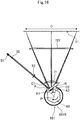
- Fig. 16 illustrates that the flow of wind (flow of air blown out from the first gap K1) during the rotation of the polygon mirror 63 is indicated by a white arrow.
- L1>L2 since high-temperature wind in the vicinity of the polygon mirror 63 reaches the first scanning lens 71, optical performance is affected due to an increase in the temperature of the first scanning lens 71.
- L1 ⁇ L2 since the above wind (white arrow) is less likely to reach the first scanning lens 71.
- Fig. 17 illustrates a sectional view of the peripheral wall 651B of the first cover part 651 when the polygon mirror 63 has a regular hexagonal section and n is 2. Since the number of surfaces of the polygon mirror 63 is 6, ⁇ is 120 ° according to Equation (3).
- L1 ⁇ L2 As illustrated in Fig. 18 , also in the present second embodiment, L1 ⁇ L2. As illustrated in Fig. 20 , for example, when L1>L2, since high-temperature wind (white arrows) in the vicinity of the polygon mirror 63 reaches the first scanning lens 71, optical performance is affected due to an increase in the temperature of the first scanning lens 71. On the other hand, when L1 ⁇ L2, since the above wind (white arrow) is less likely to reach the first scanning lens 71 as illustrated in Fig. 19 , it is possible to reduce an increase in the temperature of the first scanning lens 71, so that it is possible to suppress the deterioration of the optical performance of the first scanning lens 71.
- Fig. 21 illustrates a sectional view of the peripheral wall 651B of the first cover part 651 when the polygon mirror 63 has a regular pentagonal section and n is 1. Since the number of surfaces of the polygon mirror 63 is 5, ⁇ is 72 ° according to Equation (3).
- Fig. 22 illustrates a sectional view of the peripheral wall 651B of the first cover part 651 when the polygon mirror 63 has a regular pentagonal section and n is 2. Since the number of surfaces of the polygon mirror 63 is 5, ⁇ is 144 ° according to Equation (1). When the opening angle ⁇ of the first opening 651C is 144 °, it is possible to achieve the same effects as those of the aforementioned [A1], [B], and [C].
- the first opening 651C may also be formed such that the opening angle ⁇ satisfies Equations (1) and (2) below.
- n is 1, 49.8 ° ⁇ 70.2 ° according to Equations (1) and (2) (the number of surfaces of the polygon mirror 63 is 6).
- Equations (1) and (2) indicate that the opening angle ⁇ of the first opening 651C is within +/-17% of the opening angle ⁇ of the first opening 651C in the first embodiment.
- the noise level is smaller than those of the noise generated by the first pressure and the noise generated by the second pressure.
- the non-sealed type first cover part 651 it is possible to sufficiently reduce the noise generated by the rotation of the polygon mirror 63.
Abstract
Description
- The technology of the present disclosure relates to a light deflecting device.
- In general, a light deflecting device, is provided in an image forming apparatus, for example. The light deflecting device includes a rotary polyhedron and a cover that covers the rotary polyhedron, and the cover is formed with an opening facing a peripheral surface of the rotary polyhedron. Light emitted from a light source is irradiated to the peripheral surface of the rotary polyhedron through the opening of the cover, and the rotary polyhedron allows the light to be deflected and scanned with respect to an image carrying member as an object to be irradiated through the opening while rotating about an axial center thereof. In this way, an electrostatic latent image is formed on a surface of the image carrying member.
- Since the cover of this type of light deflecting device is a non-sealed type cover formed with the opening, noise generated by the rotation of the rotary polyhedron leaks out of the cover from the opening. In this regard, in the related art, the noise is reduced by forming the opening as small as possible.
- A light deflecting device of an aspect of the present disclosure includes a rotary polyhedron and a cover that covers the rotary polyhedron. The cover includes an opening facing a peripheral surface of the rotary polyhedron. Light beam emitted from a light source is irradiated to the peripheral surface of the rotary polyhedron through the opening of the cover. The rotary polyhedron allows the light beam to be deflected and scanned with respect to an object to be irradiated through the opening while rotating about an axial center thereof.
- In the light deflecting device, when an opening angle of the opening centered on the axial center of the rotary polyhedron is θ and n is set as a natural number smaller than a number of surfaces of the rotary polyhedron, θ satisfies Equation (1) θ>((360 °/the number of surfaces of the rotary polyhedron)×n)×0.83 ··· (1) and Equation (2) θ<((360 °/the number of surfaces of the rotary polyhedron)×n)×1.17 ··· (2).
- A light deflecting device of another aspect of the present disclosure includes a rotary polyhedron and a cover that covers the rotary polyhedron. The cover includes an opening facing a peripheral surface of the rotary polyhedron. Light beam emitted from a light source is irradiated to the peripheral surface of the rotary polyhedron through the opening of the cover. The rotary polyhedron allows the light beam to be deflected and scanned with respect to an object to be irradiated through the opening while rotating about an axial center thereof.
- In the light deflecting device, when an opening angle of the opening centered on the axial center of the rotary polyhedron is θ and n is set as a natural number smaller than a number of surfaces of the rotary polyhedron, θ satisfies Equation (3) θ≒ (360 °/the number of surfaces of the rotary polyhedron)xn.
- An optical scanning device of another aspect of the present disclosure includes the light deflecting device and the light source.
- An image forming apparatus of another aspect of the present disclosure includes the optical scanning device and the object to be irradiated. The object to be irradiated is a an image carrying member having a surface on which an electrostatic latent image is formed.
-
-
Fig. 1 is a sectional view illustrating a schematic configuration of an image forming apparatus. -
Fig. 2 is an optical path diagram illustrating a configuration of a sub-scanning section (a surface corresponding to a section including an optical axis of an optical system and a sub-scanning direction) of an optical scanning device. -
Fig. 3 is an optical path diagram illustrating a configuration of a main scanning section (a surface corresponding to a section perpendicular to a sub-scanning direction) of an optical scanning device. -
Fig. 4 is a perspective view illustrating a schematic configuration of a light deflecting device. -
Fig. 5 is a sectional view of a light deflecting device. -
Fig. 6 is a view of a light deflecting device viewed from one side (upper side) in a second direction. -
Fig. 7 is a sectional view of a cover body or the like of a light deflecting device. -
Fig. 8 is a view of a light deflecting device viewed from the other side (rear side) in a third direction. -
Fig. 9 is a perspective view of a light deflecting device viewed from a front upper side. -
Fig. 10 is a perspective view of a light deflecting device viewed from a rear upper side. -
Fig. 11 is a view illustrating a section of a peripheral wall of a first cover part and a polygon mirror. -
Fig. 12 is a view illustrating a relation between an opening angle of a first opening and a noise level. -
Fig. 13 is a view illustrating a variation in air pressure (first pressure) between a deflection surface of a polygon mirror and a first opening end of a first opening (a first gap K1). -
Fig. 14 is a view illustrating a variation in air pressure (second pressure) between a deflection surface of a polygon mirror and a second opening end of a first opening (a second gap K2). -
Fig. 15 is a view illustrating a relation between a synthesized amplitude and a phase difference (phase difference between a first waveform of a pressure variation in first pressure and a second waveform of a pressure variation in second pressure). -
Fig. 16 is an optical path diagram illustrating a configuration of a main scanning section of an optical scanning device, which illustrates the flow of air generated by the rotation of a polygon mirror. -
Fig. 17 is a view illustrating a section of a peripheral wall of a first cover part of a second embodiment and a polygon mirror. -
Fig. 18 is an optical path diagram illustrating a configuration of a main scanning section of an optical scanning device of a second embodiment. -
Fig. 19 is a view illustrating a second embodiment and is an optical path diagram illustrating a configuration of a main scanning section of an optical scanning device, which illustrates the flow of air generated by the rotation of a polygon mirror. -
Fig. 20 is a view illustrating a comparative example of a second embodiment and is an optical path diagram illustrating a configuration of a main scanning section of an optical scanning device, which illustrates the flow of air generated by the rotation of a polygon mirror. -
Fig. 21 is a view illustrating a third embodiment and is a view illustrating a section of a peripheral wall of a first cover part and a polygon mirror. -
Fig. 22 is a view illustrating a fourth embodiment and is a view illustrating a section of a peripheral wall of a first cover part and a polygon mirror. - Hereinafter, an example of an embodiment will be described on the basis of the drawings.
-
Fig 1 illustrates animage forming apparatus 1. Theimage forming apparatus 1 is a tandem type color printer (theimage forming apparatus 1 may be a copy machine or a multifunctional peripheral). Theimage forming apparatus 1 has an approximately rectangularparallelepiped body housing 10. - The
body housing 10 receives a plurality of processing units for performing image forming processing on a sheet therein. In the present embodiment, the processing units includeimage forming units optical scanning device 23, anintermediate transfer unit 28, and afixing device 30. - The
body housing 10 is provided on the upper surface thereof with asheet discharge tray 11. Asheet discharge port 12 is opened in opposition to thesheet discharge tray 11. A manualsheet feeding tray 13 is attached to a sidewall of thebody housing 10 so as to be freely openable and closable. Asheet feeing cassette 14 is detachably mounted at a lower part of thebody housing 10. - The
image forming units image forming units - Each of the
image forming units photosensitive drum 21, a developingdevice 24 for forming the toner image by attaching a developer to the electrostatic latent image, aprimary transfer roller 26 for primarily transferring the toner image formed on thephotosensitive drum 21, and a cleaning device 27 for removing residual toner on the drum peripheral surface of thephotosensitive drum 21, and theimage forming units toner containers device 24, respectively. - In the following description, when the
photosensitive drum 21 provided in each of theimage forming units image forming unit 2Y is referred to as a "firstphotosensitive drum 21Y". Furthermore, the photosensitive drum provided in the image forming unit 2C is referred to as a "secondphotosensitive drum 21C". The photosensitive drum provided in theimage forming unit 2M is referred to as a "thirdphotosensitive drum 21M", and the photosensitive drum provided in the image forming unit 2Bk is referred to as a "fourth photosensitive drum 21Bk". - The
optical scanning device 23 forms the electrostatic latent image on the drum peripheral surface of thephotosensitive drum 21 of each color. Theoptical scanning device 23 includes an incident optical system having a plurality of light sources prepared for each color, a light deflecting device 6 (seeFig. 2 andFig. 3 ) that deflects light beam emitted from the light sources, and an image forming optical system that forms an image of the light beam deflected by thelight deflecting device 6 on the drum peripheral surface of thephotosensitive drum 21 of each color and allows the light beam to be scanned on the drum peripheral surface of thephotosensitive drum 21 of each color. Theoptical scanning device 23 will be described in detail below. - The
intermediate transfer unit 28 primarily transfers the toner image formed on thephotosensitive drum 21. Theintermediate transfer unit 28 includes a transfer belt 281 that rotates in contact with the drum peripheral surface of eachphotosensitive drum 21, and a drivingroller 282 and a drivenroller 283 over which the transfer belt 281 is stretched. The transfer belt 281 is pressed to the drum peripheral surface of eachphotosensitive drum 21 by theprimary transfer roller 26. The toner image on thephotosensitive drum 21 of each color is superimposed on the same place of the transfer belt 281 and is primarily transferred. In this way, a full-color toner image is formed on the transfer belt 281. - A
secondary transfer roller 29 is arranged to face the drivingroller 282 and forms a secondary transfer nip part T with the transfer belt 281 interposed therebetween. The full-color toner image of the transfer belt 281 is secondarily transferred to a sheet at the secondary transfer nip part T. Toner remaining on the peripheral surface of the transfer belt 281 is collected by abelt cleaning device 284 arranged to face the drivenroller 283. - The fixing
device 30 includes a fixingroller 31 having a heat source incorporated therein and apressure roller 32 that forms a fixing nip part N together with the fixingroller 31. The fixingdevice 30 heats and presses the sheet, on which the toner image has been transferred at the secondary transfer nip part T, at the fixing nip part N, thereby allowing toner to be welded to the sheet. The sheet subjected to the fixing process is discharged from thesheet discharge port 12 to thesheet discharge tray 11. - The
body housing 10 is provided therein with the sheet conveyance path for conveying a sheet. The sheet conveyance path includes a main conveyance path P1 extending in a vertical direction through the secondary transfer nip part T and the fixingdevice 30 from the vicinity of a lower part of thebody housing 10 to the vicinity of an upper part thereof. A downstream end of the main conveyance path P1 is connected to thesheet discharge port 12. A reverse conveyance path P2 for conveying a sheet in a reverse direction during duplex printing extends from the lowermost stream end to the vicinity of an upstream end of the main conveyance path P1. Furthermore, a manual sheet conveyance path P3 from the manualsheet feeding tray 13 to the main conveyance path P1 is arranged above thesheet feeing cassette 14. - The
sheet feeing cassette 14 receives a bundle of sheets. On the rear upper side of thesheet feeing cassette 14, a pick-uproller 151 for delivering sheets of the uppermost layer of the bundle of the sheets one by one and a sheet feedingroller pair 152 for sending the sheets to the upstream end of the main conveyance path P1 are provided. - Sheets placed on the manual
sheet feeding tray 13 are sent to the upstream end of the main conveyance path P1 through the manual sheet conveyance path P3. On an upstream side from the secondary transfer nip part T of the main conveyance path P1, a resistroller pair 153 is arranged to send the sheets to the transfer nip part. - When the sheet is subjected to one side printing (image formation), the sheet is sent to the main conveyance path P1 from the
sheet feeing cassette 14 or the manualsheet feeding tray 13. Then, the toner image is transferred to the sheet at the secondary transfer nip part T. Furthermore, toner is fixed to the sheet by the fixingdevice 30. The sheet with the toner fixed thereto is discharged from thesheet discharge port 12 to thesheet discharge tray 11. - When the sheet is subjected to duplex printing, the aforementioned transfer process and fixing process are performed on one side of the sheet and then the sheet is subjected to switchback conveyance. Then, the sheet is returned to the vicinity of the upstream end of the main conveyance path P1 through the reverse conveyance path P2. Thereafter, the transfer process and the fixing process are performed on the other side of the sheet. The sheet subjected to the fixing process is discharged from the
sheet discharge port 12 to thesheet discharge tray 11. - Next, the
optical scanning device 23 will be described in detail. In the following description, with reference toFig. 4 , a longitudinal direction in which aboard 61 provided in thelight deflecting device 6 extends is referred to as a "first direction A1", and a direction perpendicular to one main surface of theboard 61 is referred to as a "second direction A2". Furthermore, a direction intersecting with the first direction A1 and perpendicular to the second direction A2 is referred to as a "third direction A3", and a direction perpendicular to both directions of the second direction A2 and the third direction A3 is referred to as a "fourth direction A4". - The
optical scanning device 23 is horizontally arranged below theimage forming units intermediate transfer unit 28. In theoptical scanning device 23, the second direction A2 coincides with the vertical direction. The third direction A3 coincides with a front and rear direction corresponding to the movement direction of the transfer belt 281 that rotates, and the fourth direction A4 coincides with a right and left direction corresponding to a rotation axis direction (axial center direction) of thephotosensitive drum 21. - The first direction A1 is a direction intersecting with the third direction A3 and the fourth direction A4 at an approximately 45 °. In the second direction A2 coinciding with the vertical direction, an upper side in the vertical direction is referred to as "one side" and a lower side in the vertical direction is referred to as "the other side".
- In the third direction A3 coinciding with the front and rear direction, a front side in the front and rear direction is referred to as "one side" and a rear side in the front and rear direction is referred to as "the other side". In the fourth direction A4 coinciding with the right and left direction, a right side in the right and left direction is referred to as "one side" and a left side in the right and left direction is referred to as "the other side".
- As illustrated in
Fig. 2 , theoptical scanning device 23 scans the drumperipheral surface 211 of the firstphotosensitive drum 21Y for yellow by yellow light beam LY. Similarly, theoptical scanning device 23 scans the drumperipheral surfaces 211 of the secondphotosensitive drum 21C for cyan, the thirdphotosensitive drum 21M for magenta, and the fourth photosensitive drum 21Bk for black by cyan light beam LC, magenta light beam LM, and black light beam LBk, respectively. - The yellow light beam LY is laser light beam for yellow image drawing and the cyan light beam LC is laser light beam for cyan image drawing. The magenta light beam LM is laser light beam for magenta image drawing and the black light beam LBk is laser light beam for black image drawing.
- As illustrated in
Fig. 2 andFig. 3 , theoptical scanning device 23 includes an incidentoptical system 5 arranged in the optical path of each color light beam, onelight deflecting device 6 shared by four colors, afirst scanning lens 71, andsecond scanning lenses optical scanning device 23 includes reflective mirrors 73Y1 and 73Y2 for yellow, reflective mirrors 73C1 and 73C2 for cyan, reflective mirrors 73M1, 73M2 and 73M3 for magenta, and a reflective mirror 73Bk for black. These are received in anoptical housing 4. - The reflective mirrors 73Y1 and 73Y2 for yellow reflect the yellow light beam LY, and the reflective mirrors 73C1 and 73C2 for cyan reflect the cyan light beam LC. The reflective mirrors 73M1, 73M2 and 73M3 for magenta reflect the magenta light beam LM, and the reflective mirror 73Bk for black reflects the black light beam LBk.
- The
first scanning lens 71, thesecond scanning lenses - The
optical housing 4 has a light deflecting device receiving part 41 (seeFig. 4 ) serving as a region for receiving thelight deflecting device 6. The light deflectingdevice receiving part 41 has a placingsurface 411 on which thelight deflecting device 6 is placed. - The incident
optical system 5 is received in theoptical housing 4 and is an optical system for allowing each color light beam to be incident on adeflection surface 631 which is a peripheral surface of a polygon mirror 63 (corresponding to a rotary polyhedron) to be described below. As illustrated inFig. 3 , the incidentoptical system 5 includes alight source 51, acollimator lens 52, and acylindrical lens 53. - The
light source 51 is composed of a laser element and emits light beam to be irradiated to thedeflection surface 631 of thepolygon mirror 63. Thecollimator lens 52 converts the light beam diffused after being emitted from thelight source 51 into parallel light. Thecylindrical lens 53 converts the parallel light from thecollimator lens 52 into linear light long in the fourth direction A4 and forms an image of the linear light on thedeflection surface 631 of thepolygon mirror 63. - As described above, the fourth direction A4 is a direction coinciding with the right and left direction corresponding to the rotation axis direction of the
photosensitive drum 21 and coincides with the main scanning direction of scanning with respect to thephotosensitive drum 21 by theoptical scanning device 23. - The
first scanning lens 71 is a lens having distortion aberration (fθ characteristic) in which an angle of incident light beam is proportional to an image height and is a long lens extending along the fourth direction A4 (main scanning direction). Thefirst scanning lens 71 collects light beam reflected by thedeflection surface 631 of thepolygon mirror 63. - Similarly to the
first scanning lens 71, thesecond scanning lens 72Y is a lens having the distortion aberration (fθ characteristic) and is a long lens extending along the fourth direction A4 (main scanning direction). Thesecond scanning lenses 72Y collects the yellow light beam LY having passed through thefirst scanning lens 71 and forms an image of the yellow light beam LY on the drumperipheral surfaces 211 of the firstphotosensitive drum 21Y. - Similarly to the
first scanning lens 71, thesecond scanning lens 72C is a lens having the distortion aberration (fθ characteristic) and is a long lens extending along the fourth direction A4 (main scanning direction). Thesecond scanning lenses 72C collects the cyan light beam LC having passed through thefirst scanning lens 71 and forms an image of the cyan light beam LC on the drumperipheral surfaces 211 of the secondphotosensitive drum 21C. - Similarly to the
first scanning lens 71, thesecond scanning lens 72M is a lens having the distortion aberration (fθ characteristic) and is a long lens extending along the fourth direction A4 (main scanning direction). Thesecond scanning lenses 72M collects the magenta light beam LM having passed through thefirst scanning lens 71 and forms an image of the magenta light beam LM on the drumperipheral surfaces 211 of the thirdphotosensitive drum 21M. - Similarly to the
first scanning lens 71, the second scanning lens 72Bk is a lens having the distortion aberration (fθ characteristic) and is a long lens extending along the fourth direction A4 (main scanning direction). The second scanning lenses 72Bk collects the black light beam LBk having passed through thefirst scanning lens 71 and forms an image of the black light beam LBk on the drumperipheral surfaces 211 of the fourth photosensitive drum 21Bk. - The reflective mirrors 73Y1 and 73Y2 for yellow reflect the yellow light beam LY on the image forming optical path of the yellow light beam LY having passed through the
first scanning lens 71. - The reflective mirrors 73C1 and 73C2 for cyan reflect the cyan light beam LC on the image forming optical path of the cyan light beam LC having passed through the
first scanning lens 71. - The reflective mirrors 73M1, 73M2 and 73M3 for magenta reflect the magenta light beam LM on the image forming optical path of the magenta light beam LM having passed through the
first scanning lens 71. - As illustrated in
Fig. 2 andFig. 3 , the yellow light beam LY reflected by thedeflection surface 631 of thepolygon mirror 63 is collected by thefirst scanning lens 71. Then, the yellow light beam LY is reflected by the reflective mirror 73Y1 for yellow and passes through thesecond scanning lens 72Y. Thereafter, the yellow light beam LY is reflected by the reflective mirror 73Y2 for yellow and the image of the yellow light beam LY is formed on the drumperipheral surfaces 211 of the firstphotosensitive drum 21Y. - The cyan light beam LC reflected by the
deflection surface 631 of thepolygon mirror 63 is collected by thefirst scanning lens 71. Then, the cyan light beam LC is reflected by the reflective mirror 73C1 for cyan and passes through thesecond scanning lens 72C. Thereafter, the cyan light beam LC is reflected by the reflective mirror 73C2 for cyan and the image of the cyan light beam LC is formed on the drumperipheral surfaces 211 of the secondphotosensitive drum 21C. - The magenta light beam LM reflected by the
deflection surface 631 of thepolygon mirror 63 is collected by thefirst scanning lens 71. Then, the magenta light beam LM is reflected by the reflective mirrors 73M1 and 73M2 for magenta and passes through thesecond scanning lens 72M. Thereafter, the magenta light beam LM is reflected by the reflective mirror 73M3 for magenta and the image of the magenta light beam LM is formed on the drumperipheral surfaces 211 of the thirdphotosensitive drum 21M. - The black light beam LBk reflected by the
deflection surface 631 of thepolygon mirror 63 is collected by thefirst scanning lens 71 and the second scanning lens Bk. Thereafter, the black light beam LBk is reflected by the reflective mirror 73Bk for black and the image of the black light beam LBk is formed on the drumperipheral surfaces 211 of the fourth photosensitive drum 21Bk. - As illustrated in
Fig. 4 andFig. 5 , thelight deflecting device 6 includes theboard 61, a driving motor 62 (corresponding to a driving unit), thepolygon mirror 63, adriver IC 641, acapacitor 642, aconnector 643, and acover body 65. - As illustrated in
Fig. 4 andFig. 6 , theboard 61 is a rectangular plate-shaped circuit board having a predetermined length in the first direction A1. Theboard 61 is fixed to the placingsurface 411 of the light deflectingdevice receiving part 41 of theoptical housing 4. - As illustrated in
Fig. 7 , the drivingmotor 62 includes amotor body 621 and arotating shaft 622 and is fixed to the placingsurface 411 to drive and rotate thepolygon mirror 63. Therotating shaft 622 protrudes from themotor body 621 and extends in the second direction A2 perpendicular to one main surface of theboard 61. When a driving current is inputted to themotor body 621, therotating shaft 622 rotates and thepolygon mirror 63 rotates about an axial center P thereof. - As illustrated in
Fig. 3 andFig. 7 , thepolygon mirror 63 is a polygon mirror having a regular hexagonal section. Thepolygon mirror 63 has six deflection surfaces 631 (corresponding to peripheral surfaces) corresponding to respective sides of the regular hexagon. The light beam emitted from thelight source 51 is irradiated to the deflection surfaces 631. Thepolygon mirror 63 is integrally and rotatably provided at an end of one side (upper side) of therotating shaft 622 in the second direction A2. Thepolygon mirror 63 rotates about the axial center P together with the rotation of therotating shaft 622 and allows the light beam to be deflected and scanned with respect to the drumperipheral surface 211 of thephotosensitive drum 21. InFig. 3 , a reference numeral D denotes a scanning region. InFig. 3 andFig. 11 , thepolygon mirror 63 rotates about the axial center P in a clockwise direction. - As illustrated in
Fig. 4 to Fig. 10 , thecover body 65 is fixed to the placingsurface 411 of the light deflectingdevice receiving part 41 of theoptical housing 4, and covers thepolygon mirror 63 and the drivingmotor 62. Thecover body 65 prevents noise generated by the rotation of thepolygon mirror 63 and prevents dust or the like from adhering to thepolygon mirror 63. Thecover body 65 includes afirst cover part 651 and a second cover part 652 (corresponding to cover parts). - As illustrated in
Fig. 7 , thefirst cover part 651 covers thepolygon mirror 63 from one side (upper side) in the second direction A2 and forms a first space S1 where thepolygon mirror 63 is disposed. Thefirst cover part 651 includes a disc-shapedtop wall 651A and a cylindricalperipheral wall 651B. Thetop wall 651A is arranged on one side (upper side) in the second direction A2 in parallel to the placing surface 411 (seeFig. 4 ). Theperipheral wall 651B extends toward the other side (lower side) in the second direction A2 from an outer peripheral edge of thetop wall 651A. Theperipheral wall 651B and thepolygon mirror 63 are positioned concentrically. - The
peripheral wall 651B is formed with afirst opening 651C (corresponding to an opening) facing thedeflection surface 631 of thepolygon mirror 63. As illustrated inFig. 10 andFig. 11 , thefirst opening 651C is a long hole along a peripheral direction of theperipheral wall 651B. InFig. 11 , a reference numeral A denotes a first opening end of thefirst opening 651C on an upstream side in the rotation direction of thepolygon mirror 63, and a reference numeral B denotes a second opening end of thefirst opening 651C on a downstream side in the rotation direction of thepolygon mirror 63. - As illustrated in
Fig. 3 , thefirst opening 651C guides the light beam emitted from thelight source 51 to the inside of thefirst cover part 651, and guides the light beam deflected by the deflection surfaces 631 of thepolygon mirror 63 to the outside of thefirst cover part 651. Thefirst opening 651C also has a function as an opening that allows airflow generated by the rotation of thepolygon mirror 63 to pass therethrough. Thefirst opening 651C will be described in detail below. - The
second cover part 652 forms a second space S2 (seeFig. 7 ), where the drivingmotor 62 is disposed, on the other side (lower side) of thefirst cover part 651 in the second direction A2. Thesecond cover part 652 is connected to thefirst cover part 651. The second space S2 of thesecond cover part 652 and the first space S1 of thefirst cover part 651 communicate with each other. As illustrated inFig. 4 , thesecond cover part 652 includes a first extendingpart 653 and a second extendingpart 654. - As illustrated in
Fig. 7 andFig. 9 , the first extendingpart 653 includes a firstupper wall 653A and a firstvertical wall 653B. The firstupper wall 653A extends from a part of the lower end of theperipheral wall 651B of the first cover part 651 (a part of the peripheral part of the lower end) to one side (front side) in the third direction A3. The firstvertical wall 653B extends downward from the front end of the firstupper wall 653A. The lower end of the firstvertical wall 653B is bent outward to constitute a mountingflange 653C. The mountingflange 653C is fixed to the placing surface 411 (seeFig. 4 ) of the light deflectingdevice receiving part 41 of thehousing 4. - As illustrated in
Fig. 9 , the second extendingpart 654 includes a secondupper wall 654A extending from a remaining part of the lower end of theperipheral wall 651B (a part other than the aforementioned part, that is, the remaining part of the peripheral part of the lower end) to one side (right side) and the other side (left side) in the fourth direction A4. - As illustrated in
Fig. 6 andFig. 9 , the secondupper wall 654A is formed in a trapezoidal shape that gets narrower on an opposite side (the other side (rear side) in the third direction A3) of the first extendingpart 653 when viewed from the second direction A2 (vertical direction). As illustrated inFig. 10 , a secondvertical wall 654B extends from a pair of right and left side edges corresponding to oblique sides of the trapezoid to the other side (lower side) in the second direction A2. The lower end of the secondvertical wall 654B is bent outward to constitute a mountingflange 654C. The mountingflange 654C is fixed to the placing surface 411 (seeFig. 4 ) of the light deflectingdevice receiving part 41 of thehousing 4. - As illustrated in
Fig. 6 andFig. 9 , since the firstupper wall 653A extends from a part of the lower end of theperipheral wall 651B to the one side (front side) in the third direction A3, a front edge of the secondupper wall 654A corresponding to a long side of the trapezoid is divided into a front edge part 655A1 on the right side and a front edge part 655A2 on the left side of theperipheral wall 651B. Furthermore, as illustrated inFig. 9 , a lower side of the front edge part 655A1 on the right side of the secondupper wall 654A and a lower side of a right side edge of the firstupper wall 653A are opened and a lower side of the front edge part 655A2 on the left side of the secondupper wall 654A and a lower side of a left side edge of the firstupper wall 653A are opened, so that these openings constitute asecond opening 656A (corresponding to an air vent port). - Furthermore, as illustrated in
Fig. 8 andFig. 10 , a lower side of a rear edge of the secondupper wall 654A corresponding to a short side of the trapezoid is opened to constitute a third opening 658 (corresponding to an air vent port). Thesecond opening 656A and thethird opening 658 have a function of circulating the airflow generated by the rotation of thepolygon mirror 63. In this way, it is possible to cool the drivingmotor 62 that drives thepolygon mirror 63 and electronic members around the drivingmotor 62. As a consequence, it is possible to avoid operation failure due to an increase in the temperature of the drivingmotor 62 and the electronic members. - When the
polygon mirror 63 rotates, air in thefirst cover part 651 is pushed in the rotation direction by a corner of thepolygon mirror 63. Then, the air in thefirst cover part 651 is blown out from a first gap K1 (seeFig. 11 ) between the first opening end A of thefirst opening 651C and thedeflection surface 631 of thepolygon mirror 63. Furthermore, air is suck into thefirst cover part 651 from a second gap K2 (seeFig. 11 ) between the second opening end B of thefirst opening 651C and thedeflection surface 631 of thepolygon mirror 63. - Since the
peripheral wall 651B of thefirst cover part 651 has a circular section and thepolygon mirror 63 has a regular hexagonal section, the first gap K1 and the second gap K2 change depending on the rotation of thepolygon mirror 63. - Accordingly, first pressure of the air (air in the first gap K1) between the
deflection surface 631 of thepolygon mirror 63 and the first opening end A of thefirst opening 651C varies periodically with the rotation of the polygon mirror 63 (seeFig. 13 ). Furthermore, second pressure of the air (air in the second gap K2) between thedeflection surface 631 of thepolygon mirror 63 and the second opening end B of thefirst opening 651C varies periodically with the rotation of the polygon mirror 63 (seeFig. 14 ). The first pressure and the second pressure vary by one cycle in the rotation of one surface of the polygon mirror 63 (60 ° rotation of the polygon mirror 63). - Since the
first opening 651C is formed in theperipheral wall 651B of thefirst cover part 651 that covers thepolygon mirror 63, noise generated by the rotation of thepolygon mirror 63 is leaked out of thefirst opening 651C to the outside of thefirst cover part 651. In this regard, in the present embodiment, thefirst opening 651C of thefirst cover part 651 is formed as follows, so that noise is reduced. - As illustrated in
Fig. 11 , when an opening angle of thefirst opening 651C centered on the axial center P of thepolygon mirror 63 is θ and n is set as a natural number smaller than the number of surfaces of thepolygon mirror 63, thefirst opening 651C is formed such that the opening angle θ satisfies the following Equation (3).
-
Fig. 11 is a sectional view of theperipheral wall 651B of thefirst cover part 651 when n is 1 (sectional view (main scanning sectional view) in a direction perpendicular to the axial center direction of the polygon mirror 63). Since the number of surfaces of thepolygon mirror 63 is 6, θ≒ 60 ° according to Equation (1) below. In the present embodiment, n is set to 60 °. When the opening angle θ of thefirst opening 651C is 60 °, a noise level is reduced because of the following reason. - In the present embodiment,
- [A] Since the
first opening 651C is formed such that the opening angle θ satisfies Equation (1) below, when one of the six corners of thepolygon mirror 63 is positioned near the first opening end A as illustrated inFig. 11 , another one corner is positioned near the second opening end B. Even when the center between a pair of adjacent corners of thepolygon mirror 63 is positioned near the first opening end A, the center between another pair of adjacent corners thereof is positioned near the second opening end B similarly to the above. - [B] That is, the first gap K1 and the second gap K2 always have approximately the same length during the rotation of the
polygon mirror 63, so that the first pressure and the second pressure have approximately the same magnitude (absolute value). On the other hand, since air in thefirst cover part 651 is blown out from the first gap K1 and air is suck into thefirst cover part 651 from the second gap K2, the phase of a pressure variation in the first pressure and the phase of a pressure variation in the second pressure are shifted by 180 ° (corresponding to 0.5 cycle) (seeFig. 13 andFig. 14 ). - [C] In this way, the phase of sound generated in the air blowing port near the first gap K1 and the phase of sound generated in the air suction port near the second gap K2 are also shifted by 180 °. As a consequence, these sounds are mutually canceled out and a noise level is reduced. Consequently, even when the non-sealed type
first cover part 651 is used, it is possible to sufficiently reduce noise generated by the rotation of thepolygon mirror 63. - When n is 2, θ is 120 °, and when n is 3, θ is 180 °. As described above, even when n is a natural number of 2, 3, ···, which is smaller than the number of surfaces of the
polygon mirror 63, it is possible to achieve the same effects as those of the aforementioned [A] to [C]. That is, when thefirst opening 651C is formed such that the opening angle θ satisfies Equation (3), it is possible to reduce the noise level. As illustrated inFig. 12 , it has been confirmed by experiments that the noise level is reduced when θ is 60 °, 120 °, and 180 °. -
Fig. 15 illustrates a relation between a synthesized amplitude and a phase difference (phase difference between a first waveform of the pressure variation in the first pressure and a second waveform of the pressure variation in the second pressure). The synthesized amplitude is an amplitude of a waveform obtained by synthesizing the first waveform and the second waveform. The amplitude of the first waveform and the amplitude of the second waveform (amplitude of a basic waveform) are both 1. - As illustrated in
Fig. 15 , in a range in which the phase difference is (phase difference corresponding to 0.33 cycle) to (phase difference corresponding to 0.67 cycle), the synthesized amplitude is smaller than theamplitude 1 of the basic waveform. As in the present embodiment, since the synthesized amplitude is the smallest when the phase difference is a phase difference corresponding to 0.5 cycle, the noise level is smaller than those of noise generated by the first pressure and noise generated by the second pressure. - That is, in the present embodiment, the phase difference between the first waveform and the second waveform is set such that the amplitude of the waveform obtained by synthesizing the first waveform (see
Fig. 13 ) of the pressure variation in the first pressure and the second waveform (seeFig. 14 ) of the pressure variation in the second pressure is smaller than any one of the amplitude of the first waveform and the amplitude of the second waveform. Furthermore, the opening angle θ of thefirst opening 651C is set as an angle (60 ° in the present embodiment) corresponding to the phase difference. - As illustrated in
Fig. 3 andFig. 11 , when viewed in the axial center direction of thepolygon mirror 63, if a distance between light beam C1 on the upstream side in the rotation direction of thepolygon mirror 63 and the first opening end A of thefirst opening 651C is set as L1 and a distance between light beam C2 on the downstream side in the rotation direction of thepolygon mirror 63 and the second opening end B of thefirst opening 651C is set as L2, thelight deflecting device 6 is configured such that L1 and L2 satisfy the following Equation (4).
-
Fig. 16 illustrates that the flow of wind (flow of air blown out from the first gap K1) during the rotation of thepolygon mirror 63 is indicated by a white arrow. For example, when L1>L2, since high-temperature wind in the vicinity of thepolygon mirror 63 reaches thefirst scanning lens 71, optical performance is affected due to an increase in the temperature of thefirst scanning lens 71. On the other hand, when L1<L2, since the above wind (white arrow) is less likely to reach thefirst scanning lens 71. As a consequence, it is possible to reduce an increase in the temperature of thefirst scanning lens 71, so that it is possible to suppress the deterioration of the optical performance of thefirst scanning lens 71. -
Fig. 17 illustrates a sectional view of theperipheral wall 651B of thefirst cover part 651 when thepolygon mirror 63 has a regular hexagonal section and n is 2. Since the number of surfaces of thepolygon mirror 63 is 6, θ is 120 ° according to Equation (3). - Even when θ is 120 °, it is possible to achieve the same effects as those of the aforementioned [A] to [C]. That is, since the
first opening 651C is formed such that the opening angle θ satisfies Equation (3), it is possible to reduce the noise level. As described above, it has been confirmed by experiments that the noise level is reduced when θ is 120 ° (seeFig. 12 ). - As illustrated in
Fig. 18 , also in the present second embodiment, L1<L2. As illustrated inFig. 20 , for example, when L1>L2, since high-temperature wind (white arrows) in the vicinity of thepolygon mirror 63 reaches thefirst scanning lens 71, optical performance is affected due to an increase in the temperature of thefirst scanning lens 71. On the other hand, when L1<L2, since the above wind (white arrow) is less likely to reach thefirst scanning lens 71 as illustrated inFig. 19 , it is possible to reduce an increase in the temperature of thefirst scanning lens 71, so that it is possible to suppress the deterioration of the optical performance of thefirst scanning lens 71. -
Fig. 21 illustrates a sectional view of theperipheral wall 651B of thefirst cover part 651 when thepolygon mirror 63 has a regular pentagonal section and n is 1. Since the number of surfaces of thepolygon mirror 63 is 5, θ is 72 ° according to Equation (3). - When the opening angle θ of the
first opening 651C is 72 °,
[A1] Since thefirst opening 651C is formed such that the opening angle θ satisfies Equation (3), when one of the five corners of thepolygon mirror 63 is positioned near the first opening end A, another one corner is positioned near the second opening end B. Even when the center between a pair of adjacent corners of thepolygon mirror 63 is positioned near the first opening end A, the center between another pair of adjacent corners thereof is positioned near the second opening end B similarly to the above. - Consequently, it is possible to achieve the same effects as those of the aforementioned [B] and [C].
-
Fig. 22 illustrates a sectional view of theperipheral wall 651B of thefirst cover part 651 when thepolygon mirror 63 has a regular pentagonal section and n is 2. Since the number of surfaces of thepolygon mirror 63 is 5, θ is 144 ° according to Equation (1). When the opening angle θ of thefirst opening 651C is 144 °, it is possible to achieve the same effects as those of the aforementioned [A1], [B], and [C]. - When the opening angle of the
first opening 651C centered on the axial center P of thepolygon mirror 63 is θ and n is set as a natural number smaller than the number of surfaces of thepolygon mirror 63, thefirst opening 651C may also be formed such that the opening angle θ satisfies Equations (1) and (2) below.

When n is 1, 49.8 °<θ<70.2 ° according to Equations (1) and (2) (the number of surfaces of thepolygon mirror 63 is 6). - When 49.8 °<θ<70.2 °, the noise level is reduced. The reason will be described.
- Equations (1) and (2) indicate that the opening angle θ of the
first opening 651C is within +/-17% of the opening angle θ of thefirst opening 651C in the first embodiment. This indicates that the phase difference between the first waveform of the pressure variation in the first pressure and the second waveform of the pressure variation in the second pressure in the present fifth embodiment increases/decreases by +/-0.17 cycle with respect to the phase difference in the first embodiment. In the first embodiment, there is the phase difference corresponding to 0.5 cycle. Therefore, in the range of 49.8 °<θ<70.2 °, a phase difference corresponding to 0.33 cycle to 0.67 cycle occurs in both waveforms. - As illustrated in
Fig. 15 , in the range in which the phase difference is (phase difference corresponding to 0.33 cycle) to (phase difference corresponding to 0.67 cycle), since the synthesized amplitude is smaller than theamplitude 1 of the basic waveform, the noise level is smaller than those of the noise generated by the first pressure and the noise generated by the second pressure. As described above, according to the present fifth embodiment, even when the non-sealed typefirst cover part 651 is used, it is possible to sufficiently reduce the noise generated by the rotation of thepolygon mirror 63.
Claims (4)
- A light deflecting device comprising:a rotary polyhedron (63); anda cover (651) that covers the rotary polyhedron (63),wherein the cover (651) includes:an opening (651C) facing a peripheral surface of the rotary polyhedron (63),light beam emitted from a light source (51) is irradiated to the peripheral surface of the rotary polyhedron (63) through the opening (651C) of the cover (651),the rotary polyhedron (63) is configured to allow the light beam to be deflected and scanned with respect to an object (21) to be irradiated through the opening (651C) while rotating about an axial center thereof, andwhen an opening angle of the opening (651C) centered on the axial center of the rotary polyhedron (63) is θ and n is set as a natural number smaller than a number of surfaces of the rotary polyhedron (63), θ satisfies Equations (1) and (2) below,


- A light deflecting device comprising:a rotary polyhedron (63); anda cover (651) that covers the rotary polyhedron (63),wherein the cover (651) includes:an opening (651C) facing a peripheral surface of the rotary polyhedron (63),light beam emitted from a light source (51) is irradiated to the peripheral surface of the rotary polyhedron (63) through the opening (651C) of the cover (651),the rotary polyhedron (63) is configured to allow the light beam to be deflected and scanned with respect to an object (21) to be irradiated through the opening (651C) while rotating about an axial center thereof, andwhen an opening angle of the opening (651C) centered on the axial center of the rotary polyhedron (63) is θ and n is set as a natural number smaller than a number of surfaces of the rotary polyhedron (63), θ satisfies Equation (3) below,

- The light deflecting device according to claim 1 or 2, wherein, when viewed in an axial center direction of the rotary polyhedron (63), if a distance between light beam on an upstream side in a rotation direction of the rotary polyhedron (63) and an opening end (A) of the opening (651C) of the cover (651) on the upstream side in the rotation direction of the rotary polyhedron (63) is set as L1 and a distance between light beam on a downstream side in the rotation direction of the rotary polyhedron (63) and an opening end (B) of the opening (651C) of the cover (651) on the downstream side in the rotation direction of the rotary polyhedron (63) is set as L2, Equation (4) below is satisfied,

- The light deflecting device according to any one of claims 1 to 3, wherein a cover (651) part that covers a driving unit of the rotary polyhedron (63) is connected to the cover (651), and
the cover (651) part is formed with air vent ports (656A and 658).
Applications Claiming Priority (1)
| Application Number | Priority Date | Filing Date | Title |
|---|---|---|---|
| JP2018153405A JP7163664B2 (en) | 2018-08-17 | 2018-08-17 | Optical deflection device, optical scanning device provided with optical deflection device, and image forming apparatus provided with optical scanning device |
Publications (2)
| Publication Number | Publication Date |
|---|---|
| EP3611553A1 true EP3611553A1 (en) | 2020-02-19 |
| EP3611553B1 EP3611553B1 (en) | 2021-11-03 |
Family
ID=67658782
Family Applications (1)
| Application Number | Title | Priority Date | Filing Date |
|---|---|---|---|
| EP19191680.8A Active EP3611553B1 (en) | 2018-08-17 | 2019-08-14 | Light deflecting device |
Country Status (4)
| Country | Link |
|---|---|
| US (1) | US10866409B2 (en) |
| EP (1) | EP3611553B1 (en) |
| JP (1) | JP7163664B2 (en) |
| CN (1) | CN110837184B (en) |
Citations (3)
| Publication number | Priority date | Publication date | Assignee | Title |
|---|---|---|---|---|
| JPH0695021A (en) * | 1992-09-16 | 1994-04-08 | Ebara Corp | Rotary polyhedral mirror device |
| JPH06308416A (en) * | 1993-04-26 | 1994-11-04 | Canon Inc | Light deflector |
| US20170299975A1 (en) * | 2016-04-15 | 2017-10-19 | Kyocera Document Solutions Inc. | Optical deflector, and optical scanning device and image forming apparatus equipped with same |
Family Cites Families (11)
| Publication number | Priority date | Publication date | Assignee | Title |
|---|---|---|---|---|
| JPH06308410A (en) * | 1993-04-23 | 1994-11-04 | Canon Inc | Light deflector |
| JP2001249298A (en) | 2000-03-03 | 2001-09-14 | Minolta Co Ltd | Image forming device |
| US7034859B2 (en) * | 2002-08-08 | 2006-04-25 | Canon Kabushiki Kaisha | Optical scanning device and image forming apparatus using the same |
| CN100447613C (en) * | 2004-12-15 | 2008-12-31 | 株式会社理光 | Optical scanner and image forming apparatus |
| JP5419640B2 (en) * | 2009-11-06 | 2014-02-19 | キヤノン株式会社 | Scanning optical device and image forming apparatus using the same |
| KR20130015405A (en) * | 2011-08-03 | 2013-02-14 | 삼성전자주식회사 | Laser scanning unit and image forming apparatus employing the same |
| JP2013200546A (en) * | 2012-02-24 | 2013-10-03 | Kyocera Document Solutions Inc | Scan lens, optical scanner, and image formation apparatus using optical scanner |
| JP6108850B2 (en) * | 2013-01-30 | 2017-04-05 | キヤノン株式会社 | Scanning optical device and image forming apparatus having the same |
| JP6361960B2 (en) * | 2014-05-26 | 2018-07-25 | 株式会社リコー | Optical scanning apparatus and image forming apparatus |
| US10274858B2 (en) * | 2016-10-21 | 2019-04-30 | Canon Kabushiki Kaisha | Image forming apparatus |
| JP7234605B2 (en) * | 2018-11-28 | 2023-03-08 | 京セラドキュメントソリューションズ株式会社 | Optical deflection device, optical scanning device provided with optical deflection device, and image forming apparatus provided with optical scanning device |
-
2018
- 2018-08-17 JP JP2018153405A patent/JP7163664B2/en active Active
-
2019
- 2019-08-14 EP EP19191680.8A patent/EP3611553B1/en active Active
- 2019-08-15 US US16/541,596 patent/US10866409B2/en active Active
- 2019-08-16 CN CN201910759965.1A patent/CN110837184B/en active Active
Patent Citations (3)
| Publication number | Priority date | Publication date | Assignee | Title |
|---|---|---|---|---|
| JPH0695021A (en) * | 1992-09-16 | 1994-04-08 | Ebara Corp | Rotary polyhedral mirror device |
| JPH06308416A (en) * | 1993-04-26 | 1994-11-04 | Canon Inc | Light deflector |
| US20170299975A1 (en) * | 2016-04-15 | 2017-10-19 | Kyocera Document Solutions Inc. | Optical deflector, and optical scanning device and image forming apparatus equipped with same |
Also Published As
| Publication number | Publication date |
|---|---|
| CN110837184A (en) | 2020-02-25 |
| JP7163664B2 (en) | 2022-11-01 |
| US10866409B2 (en) | 2020-12-15 |
| CN110837184B (en) | 2022-01-21 |
| US20200057300A1 (en) | 2020-02-20 |
| JP2020027223A (en) | 2020-02-20 |
| EP3611553B1 (en) | 2021-11-03 |
Similar Documents
| Publication | Publication Date | Title |
|---|---|---|
| CN104834193B (en) | Imaging device | |
| JP4925623B2 (en) | Optical scanning apparatus and image forming apparatus | |
| CN111240008B (en) | Optical deflecting device, optical scanning device having the same, and image forming apparatus having the same | |
| JP5219549B2 (en) | Optical scanning device | |
| JP6460035B2 (en) | Optical deflecting device, optical scanning device including the same, and image forming apparatus | |
| CN107300764B (en) | Light deflection device, and optical scanning device and image forming apparatus provided with the same | |
| JP2015225100A (en) | Optical scanner and image forming apparatus | |
| EP3611553B1 (en) | Light deflecting device | |
| JP2007292972A (en) | Image forming apparatus | |
| US11209771B2 (en) | Image forming apparatus | |
| US11487215B2 (en) | Optical deflector, optical scanning device equipped therewith, and image forming apparatus | |
| EP3467568B1 (en) | Optical scanning device and image forming apparatus including the same | |
| CN108604009B (en) | Optical scanning device and image forming apparatus | |
| US9423719B1 (en) | Optical scanning device and image forming apparatus using the same | |
| JP2010139610A (en) | Optical scanner and image forming apparatus | |
| JP7246245B2 (en) | OPTICAL SCANNER AND IMAGE FORMING APPARATUS INCLUDING THE SAME | |
| JP4413110B2 (en) | Optical writing apparatus and image forming apparatus | |
| JP4641547B2 (en) | Optical scanning device | |
| JP6332075B2 (en) | Optical scanning apparatus and image forming apparatus | |
| JP2020003658A (en) | Optical scanner and image forming apparatus including optical scanner | |
| JP2020086212A (en) | Optical deflector, optical scanner including optical deflector, and image forming apparatus including optical scanner | |
| JP2010113145A (en) | Optical scanner and image forming apparatus equipped with the same | |
| JP2015200841A (en) | Scanning optical device and image forming apparatus | |
| JP2010286682A (en) | Optical scanner and image forming apparatus equipped with the same | |
| JP2012073454A (en) | Optical scanner and image forming apparatus equipped with the same |
Legal Events
| Date | Code | Title | Description |
|---|---|---|---|
| PUAI | Public reference made under article 153(3) epc to a published international application that has entered the european phase |
Free format text: ORIGINAL CODE: 0009012 |
|
| STAA | Information on the status of an ep patent application or granted ep patent |
Free format text: STATUS: THE APPLICATION HAS BEEN PUBLISHED |
|
| AK | Designated contracting states |
Kind code of ref document: A1 Designated state(s): AL AT BE BG CH CY CZ DE DK EE ES FI FR GB GR HR HU IE IS IT LI LT LU LV MC MK MT NL NO PL PT RO RS SE SI SK SM TR |
|
| AX | Request for extension of the european patent |
Extension state: BA ME |
|
| STAA | Information on the status of an ep patent application or granted ep patent |
Free format text: STATUS: REQUEST FOR EXAMINATION WAS MADE |
|
| 17P | Request for examination filed |
Effective date: 20200814 |
|
| RBV | Designated contracting states (corrected) |
Designated state(s): AL AT BE BG CH CY CZ DE DK EE ES FI FR GB GR HR HU IE IS IT LI LT LU LV MC MK MT NL NO PL PT RO RS SE SI SK SM TR |
|
| GRAP | Despatch of communication of intention to grant a patent |
Free format text: ORIGINAL CODE: EPIDOSNIGR1 |
|
| STAA | Information on the status of an ep patent application or granted ep patent |
Free format text: STATUS: GRANT OF PATENT IS INTENDED |
|
| INTG | Intention to grant announced |
Effective date: 20210528 |
|
| GRAS | Grant fee paid |
Free format text: ORIGINAL CODE: EPIDOSNIGR3 |
|
| GRAA | (expected) grant |
Free format text: ORIGINAL CODE: 0009210 |
|
| STAA | Information on the status of an ep patent application or granted ep patent |
Free format text: STATUS: THE PATENT HAS BEEN GRANTED |
|
| AK | Designated contracting states |
Kind code of ref document: B1 Designated state(s): AL AT BE BG CH CY CZ DE DK EE ES FI FR GB GR HR HU IE IS IT LI LT LU LV MC MK MT NL NO PL PT RO RS SE SI SK SM TR |
|
| REG | Reference to a national code |
Ref country code: GB Ref legal event code: FG4D |
|
| REG | Reference to a national code |
Ref country code: AT Ref legal event code: REF Ref document number: 1444493 Country of ref document: AT Kind code of ref document: T Effective date: 20211115 Ref country code: CH Ref legal event code: EP |
|
| REG | Reference to a national code |
Ref country code: IE Ref legal event code: FG4D |
|
| REG | Reference to a national code |
Ref country code: DE Ref legal event code: R096 Ref document number: 602019008880 Country of ref document: DE |
|
| REG | Reference to a national code |
Ref country code: LT Ref legal event code: MG9D |
|
| REG | Reference to a national code |
Ref country code: NL Ref legal event code: MP Effective date: 20211103 |
|
| REG | Reference to a national code |
Ref country code: AT Ref legal event code: MK05 Ref document number: 1444493 Country of ref document: AT Kind code of ref document: T Effective date: 20211103 |
|
| PG25 | Lapsed in a contracting state [announced via postgrant information from national office to epo] |
Ref country code: RS Free format text: LAPSE BECAUSE OF FAILURE TO SUBMIT A TRANSLATION OF THE DESCRIPTION OR TO PAY THE FEE WITHIN THE PRESCRIBED TIME-LIMIT Effective date: 20211103 Ref country code: LT Free format text: LAPSE BECAUSE OF FAILURE TO SUBMIT A TRANSLATION OF THE DESCRIPTION OR TO PAY THE FEE WITHIN THE PRESCRIBED TIME-LIMIT Effective date: 20211103 Ref country code: FI Free format text: LAPSE BECAUSE OF FAILURE TO SUBMIT A TRANSLATION OF THE DESCRIPTION OR TO PAY THE FEE WITHIN THE PRESCRIBED TIME-LIMIT Effective date: 20211103 Ref country code: BG Free format text: LAPSE BECAUSE OF FAILURE TO SUBMIT A TRANSLATION OF THE DESCRIPTION OR TO PAY THE FEE WITHIN THE PRESCRIBED TIME-LIMIT Effective date: 20220203 Ref country code: AT Free format text: LAPSE BECAUSE OF FAILURE TO SUBMIT A TRANSLATION OF THE DESCRIPTION OR TO PAY THE FEE WITHIN THE PRESCRIBED TIME-LIMIT Effective date: 20211103 |
|
| PG25 | Lapsed in a contracting state [announced via postgrant information from national office to epo] |
Ref country code: IS Free format text: LAPSE BECAUSE OF FAILURE TO SUBMIT A TRANSLATION OF THE DESCRIPTION OR TO PAY THE FEE WITHIN THE PRESCRIBED TIME-LIMIT Effective date: 20220303 Ref country code: SE Free format text: LAPSE BECAUSE OF FAILURE TO SUBMIT A TRANSLATION OF THE DESCRIPTION OR TO PAY THE FEE WITHIN THE PRESCRIBED TIME-LIMIT Effective date: 20211103 Ref country code: PT Free format text: LAPSE BECAUSE OF FAILURE TO SUBMIT A TRANSLATION OF THE DESCRIPTION OR TO PAY THE FEE WITHIN THE PRESCRIBED TIME-LIMIT Effective date: 20220303 Ref country code: PL Free format text: LAPSE BECAUSE OF FAILURE TO SUBMIT A TRANSLATION OF THE DESCRIPTION OR TO PAY THE FEE WITHIN THE PRESCRIBED TIME-LIMIT Effective date: 20211103 Ref country code: NO Free format text: LAPSE BECAUSE OF FAILURE TO SUBMIT A TRANSLATION OF THE DESCRIPTION OR TO PAY THE FEE WITHIN THE PRESCRIBED TIME-LIMIT Effective date: 20220203 Ref country code: NL Free format text: LAPSE BECAUSE OF FAILURE TO SUBMIT A TRANSLATION OF THE DESCRIPTION OR TO PAY THE FEE WITHIN THE PRESCRIBED TIME-LIMIT Effective date: 20211103 Ref country code: LV Free format text: LAPSE BECAUSE OF FAILURE TO SUBMIT A TRANSLATION OF THE DESCRIPTION OR TO PAY THE FEE WITHIN THE PRESCRIBED TIME-LIMIT Effective date: 20211103 Ref country code: HR Free format text: LAPSE BECAUSE OF FAILURE TO SUBMIT A TRANSLATION OF THE DESCRIPTION OR TO PAY THE FEE WITHIN THE PRESCRIBED TIME-LIMIT Effective date: 20211103 Ref country code: GR Free format text: LAPSE BECAUSE OF FAILURE TO SUBMIT A TRANSLATION OF THE DESCRIPTION OR TO PAY THE FEE WITHIN THE PRESCRIBED TIME-LIMIT Effective date: 20220204 Ref country code: ES Free format text: LAPSE BECAUSE OF FAILURE TO SUBMIT A TRANSLATION OF THE DESCRIPTION OR TO PAY THE FEE WITHIN THE PRESCRIBED TIME-LIMIT Effective date: 20211103 |
|
| PG25 | Lapsed in a contracting state [announced via postgrant information from national office to epo] |
Ref country code: SM Free format text: LAPSE BECAUSE OF FAILURE TO SUBMIT A TRANSLATION OF THE DESCRIPTION OR TO PAY THE FEE WITHIN THE PRESCRIBED TIME-LIMIT Effective date: 20211103 Ref country code: SK Free format text: LAPSE BECAUSE OF FAILURE TO SUBMIT A TRANSLATION OF THE DESCRIPTION OR TO PAY THE FEE WITHIN THE PRESCRIBED TIME-LIMIT Effective date: 20211103 Ref country code: RO Free format text: LAPSE BECAUSE OF FAILURE TO SUBMIT A TRANSLATION OF THE DESCRIPTION OR TO PAY THE FEE WITHIN THE PRESCRIBED TIME-LIMIT Effective date: 20211103 Ref country code: EE Free format text: LAPSE BECAUSE OF FAILURE TO SUBMIT A TRANSLATION OF THE DESCRIPTION OR TO PAY THE FEE WITHIN THE PRESCRIBED TIME-LIMIT Effective date: 20211103 Ref country code: DK Free format text: LAPSE BECAUSE OF FAILURE TO SUBMIT A TRANSLATION OF THE DESCRIPTION OR TO PAY THE FEE WITHIN THE PRESCRIBED TIME-LIMIT Effective date: 20211103 Ref country code: CZ Free format text: LAPSE BECAUSE OF FAILURE TO SUBMIT A TRANSLATION OF THE DESCRIPTION OR TO PAY THE FEE WITHIN THE PRESCRIBED TIME-LIMIT Effective date: 20211103 |
|
| REG | Reference to a national code |
Ref country code: DE Ref legal event code: R097 Ref document number: 602019008880 Country of ref document: DE |
|
| PLBE | No opposition filed within time limit |
Free format text: ORIGINAL CODE: 0009261 |
|
| STAA | Information on the status of an ep patent application or granted ep patent |
Free format text: STATUS: NO OPPOSITION FILED WITHIN TIME LIMIT |
|
| 26N | No opposition filed |
Effective date: 20220804 |
|
| PG25 | Lapsed in a contracting state [announced via postgrant information from national office to epo] |
Ref country code: AL Free format text: LAPSE BECAUSE OF FAILURE TO SUBMIT A TRANSLATION OF THE DESCRIPTION OR TO PAY THE FEE WITHIN THE PRESCRIBED TIME-LIMIT Effective date: 20211103 |
|
| PGFP | Annual fee paid to national office [announced via postgrant information from national office to epo] |
Ref country code: DE Payment date: 20220629 Year of fee payment: 4 |
|
| PG25 | Lapsed in a contracting state [announced via postgrant information from national office to epo] |
Ref country code: SI Free format text: LAPSE BECAUSE OF FAILURE TO SUBMIT A TRANSLATION OF THE DESCRIPTION OR TO PAY THE FEE WITHIN THE PRESCRIBED TIME-LIMIT Effective date: 20211103 |
|
| PG25 | Lapsed in a contracting state [announced via postgrant information from national office to epo] |
Ref country code: MC Free format text: LAPSE BECAUSE OF FAILURE TO SUBMIT A TRANSLATION OF THE DESCRIPTION OR TO PAY THE FEE WITHIN THE PRESCRIBED TIME-LIMIT Effective date: 20211103 |
|
| REG | Reference to a national code |
Ref country code: CH Ref legal event code: PL |
|
| PG25 | Lapsed in a contracting state [announced via postgrant information from national office to epo] |
Ref country code: LU Free format text: LAPSE BECAUSE OF NON-PAYMENT OF DUE FEES Effective date: 20220814 Ref country code: LI Free format text: LAPSE BECAUSE OF NON-PAYMENT OF DUE FEES Effective date: 20220831 Ref country code: CH Free format text: LAPSE BECAUSE OF NON-PAYMENT OF DUE FEES Effective date: 20220831 |
|
| REG | Reference to a national code |
Ref country code: BE Ref legal event code: MM Effective date: 20220831 |
|
| PG25 | Lapsed in a contracting state [announced via postgrant information from national office to epo] |
Ref country code: IT Free format text: LAPSE BECAUSE OF FAILURE TO SUBMIT A TRANSLATION OF THE DESCRIPTION OR TO PAY THE FEE WITHIN THE PRESCRIBED TIME-LIMIT Effective date: 20211103 |
|
| P01 | Opt-out of the competence of the unified patent court (upc) registered |
Effective date: 20230420 |
|
| PG25 | Lapsed in a contracting state [announced via postgrant information from national office to epo] |
Ref country code: IE Free format text: LAPSE BECAUSE OF NON-PAYMENT OF DUE FEES Effective date: 20220814 Ref country code: FR Free format text: LAPSE BECAUSE OF NON-PAYMENT OF DUE FEES Effective date: 20220831 |
|
| PG25 | Lapsed in a contracting state [announced via postgrant information from national office to epo] |
Ref country code: BE Free format text: LAPSE BECAUSE OF NON-PAYMENT OF DUE FEES Effective date: 20220831 |
|
| REG | Reference to a national code |
Ref country code: DE Ref legal event code: R119 Ref document number: 602019008880 Country of ref document: DE |
|
| PG25 | Lapsed in a contracting state [announced via postgrant information from national office to epo] |
Ref country code: HU Free format text: LAPSE BECAUSE OF FAILURE TO SUBMIT A TRANSLATION OF THE DESCRIPTION OR TO PAY THE FEE WITHIN THE PRESCRIBED TIME-LIMIT; INVALID AB INITIO Effective date: 20190814 |