EP3611552B1 - Camera lens system for an endoscope, method for producing a camera lens system and an endoscope - Google Patents
Camera lens system for an endoscope, method for producing a camera lens system and an endoscope Download PDFInfo
- Publication number
- EP3611552B1 EP3611552B1 EP18189261.3A EP18189261A EP3611552B1 EP 3611552 B1 EP3611552 B1 EP 3611552B1 EP 18189261 A EP18189261 A EP 18189261A EP 3611552 B1 EP3611552 B1 EP 3611552B1
- Authority
- EP
- European Patent Office
- Prior art keywords
- lens
- focal length
- lenses
- convex
- camera lens
- Prior art date
- Legal status (The legal status is an assumption and is not a legal conclusion. Google has not performed a legal analysis and makes no representation as to the accuracy of the status listed.)
- Active
Links
Images


Classifications
-
- G—PHYSICS
- G02—OPTICS
- G02B—OPTICAL ELEMENTS, SYSTEMS OR APPARATUS
- G02B23/00—Telescopes, e.g. binoculars; Periscopes; Instruments for viewing the inside of hollow bodies; Viewfinders; Optical aiming or sighting devices
- G02B23/24—Instruments or systems for viewing the inside of hollow bodies, e.g. fibrescopes
- G02B23/2407—Optical details
- G02B23/2423—Optical details of the distal end
- G02B23/243—Objectives for endoscopes
-
- G—PHYSICS
- G02—OPTICS
- G02B—OPTICAL ELEMENTS, SYSTEMS OR APPARATUS
- G02B13/00—Optical objectives specially designed for the purposes specified below
- G02B13/18—Optical objectives specially designed for the purposes specified below with lenses having one or more non-spherical faces, e.g. for reducing geometrical aberration
-
- G—PHYSICS
- G02—OPTICS
- G02B—OPTICAL ELEMENTS, SYSTEMS OR APPARATUS
- G02B9/00—Optical objectives characterised both by the number of the components and their arrangements according to their sign, i.e. + or -
- G02B9/12—Optical objectives characterised both by the number of the components and their arrangements according to their sign, i.e. + or - having three components only
-
- G—PHYSICS
- G02—OPTICS
- G02B—OPTICAL ELEMENTS, SYSTEMS OR APPARATUS
- G02B13/00—Optical objectives specially designed for the purposes specified below
- G02B13/001—Miniaturised objectives for electronic devices, e.g. portable telephones, webcams, PDAs, small digital cameras
- G02B13/0015—Miniaturised objectives for electronic devices, e.g. portable telephones, webcams, PDAs, small digital cameras characterised by the lens design
- G02B13/002—Miniaturised objectives for electronic devices, e.g. portable telephones, webcams, PDAs, small digital cameras characterised by the lens design having at least one aspherical surface
- G02B13/0035—Miniaturised objectives for electronic devices, e.g. portable telephones, webcams, PDAs, small digital cameras characterised by the lens design having at least one aspherical surface having three lenses
-
- G—PHYSICS
- G02—OPTICS
- G02B—OPTICAL ELEMENTS, SYSTEMS OR APPARATUS
- G02B13/00—Optical objectives specially designed for the purposes specified below
- G02B13/04—Reversed telephoto objectives
Definitions
- the invention relates to a camera lens system for an endoscope, method for producing a camera lens system and an endoscope.
- the document KR 2015/0033321 A1 discloses a wide-angle photographic lens system. This system enables a correction of distortions and comprises three lenses.
- the first lens has a weak refractivity
- the second lens has a strong positive refractivity
- the third lens has a negative refractivity.
- the system satisfies the following relations:
- the document US 6, 795, 253 B2 discloses an imaging lens.
- This imaging lens includes, in order from the object side, a positive meniscus first lens component with its convex lens surface on the object side, a positive meniscus second lens component with its convex lens surface on the image side and a negative third lens component with its concave lens surface on the image side.
- optical system for taking an image.
- This optical system comprises three lens elements with refractive power, from the object side to the image side: a first positive lens element having a convex front surface and a concave rear surface, and the front surface being aspheric, a negative plastic second lens element having a concave front surface and a convex rear surface, and the front and rear surfaces thereof being aspheric, a positive plastic third lens element having a convex front surface and a concave rear surface, the front and rear surfaces thereof being aspheric, and an aperture stop located between the first and second lens elements for controlling brightness of the optical system.
- the document US 7, 408, 725 B2 discloses a single focus lens.
- This single focus lens provides and includes, in order from an object side of the single focus lens, a first lens having positive power and having a convex surface on the object side, a second lens of a negative meniscus lens and having a concave surface of the object side on its paraxial axis and a third lens of an aspherical lens having a convex surface on the object side on its paraxial axis.
- the document US 7, 468, 847 B2 discloses an optical lens system for taking an image.
- This optical lens system comprises three lens elements with refractive power, from the object side to the image side: a first positive lens element having a convex surface on the object side and a concave surface on the image side, and at least one of the object side and image-side surfaces being aspheric, a negative plastic second lens element having a concave surface on the object side and a convex surface on the image side, and the object-side and image-side surfaces thereof being aspheric, a positive plastic third lens element having a convex surface on the object side and a concave surface on the image side, the object-side and image-side surfaces thereof being aspheric and an aperture stop located in front of the first lens element for controlling brightness of the optical lens system.
- a focal length of the second lens element is f2
- a focal length of the optical lens system is f and they satisfy the relation: 0.1 ⁇
- the document US 2013/ 0222675 A1 discloses an imaging lens and imaging device.
- This imaging lens includes a first lens, a second lens and a third lens arranged from an object side to an image plane side.
- the first lens has an object-side surface with a positive curvature radius.
- the second lens has an object-side surface and an image plane-side surface with negative curvature radii.
- the third lens has an object-side surface and an image plane-side surface with positive curvature radii.
- the object-side surface and the image plane-side surface of the third lens are respectively formed as an aspheric shape having an inflexion point.
- the imaging lens satisfies the following conditional expressions: f1 ⁇ f2 1.0 ⁇ f1/f ⁇ 1.5 0.7 ⁇ f2/f3 ⁇ 1.2.
- the document US 2013/ 0222927 A1 discloses an imaging lens and imaging device.
- the imaging lens includes a first lens, a second lens and a third lens arranged from an object side to an image plane side.
- the first lens has an object-side surface having a positive curvature radius R1f and an image plane-side surface having a negative curvature radius R1r.
- the second lens has an object-side surface and an image plane-side surface with negative curvature radii.
- the third lens has an object-side surface and an image plane-side surface with positive curvature radii and formed as aspheric surfaces having inflexion points.
- the imaging lens satisfies the following conditional expressions: f1 ⁇ f2 ⁇ f3 1.0 ⁇ f1/f ⁇ 1.5 -0.02 ⁇ R1f/R1r ⁇ 0.
- the document US 2015/ 0029602 A1 discloses an imaging lens.
- the imaging lens includes a first lens having positive refractive power, a second lens having positive refractive power; and a third lens having negative refractive power, arranged in the order from an object side to an image plane side.
- the first lens and the third lens respectively have an object-side surface and an image plane-side surface whose curvature radii are both positive.
- the second lens has an image plane-side surface whose a curvature radius is negative.
- the imaging lens satisfies specific conditional expressions.
- the document US 2015/ 0029603 A1 discloses an imaging lens.
- the imaging lens includes a first lens having positive refractive power, a second lens having positive refractive power and a third lens having positive refractive power, arranged in the order from an object side to an image plane side.
- the first lens and the third lens have object-side surfaces and image plane-side surfaces, curvature radii of which are both positive.
- the imaging lens satisfies the following conditional expressions: 5.0 ⁇ (P1+P3)/P2 ⁇ 8.5 6 ⁇ f3/f1 ⁇ 30.
- a camera lens system for an endoscope comprises the following components: At least three lenses, wherein the first lens, when starting from the object side, is a negative lens, the following lenses moving toward the image side are positive lenses, wherein the system comprises the following features: 45 ⁇ V1d ⁇ 75;
- the invention with the presented components allows a cost-effective production, as well as an improved performance concerning the size of the system.
- the invention provides good optical performances, especially for the usage within the technical field of endoscopy.
- the camera lens system can also be a miniature camera system.
- a diagonal field of view ranges from 80 to 100 degrees, more preferably from 88 to 92 degrees.
- said three lenses are formed from the same material. In a more preferred embodiment, said three lenses completely consist of the same material. Technologies like wafer level optics can therefore be used for manufacturing such an optical system resulting in improved production costs and an optimized size of the resulting system.
- the three lenses are arranged along an optical axis which forms a straight line. It is further preferred that all three lenses are formed to be symmetrical to the rotation axis (optical axis). It is further preferred that no further components (changing the optical properties of the lens system) intervene said three lenses. It is further preferred that air (or another gas) fills the gaps between said lenses.
- the first lens is formed such that the condition 50 ⁇ V1d ⁇ 65 is met. According to a preferred embodiment of the invention, the first lens is formed such that the condition 50 ⁇ V1d ⁇ 55 is met.
- At least one of the following conditions is met: V1d - V2d
- the first lens is formed such that the condition 1,45 ⁇ n1d ⁇ 1,65 is met. According to a preferred embodiment of the invention, the first lens is formed such that the condition 1,50 ⁇ n1d ⁇ 1,55 is met.
- At least one of the following conditions is met:
- At least one of the following conditions is met: -2,75 ⁇ f1/f ⁇ -2,25; 1,15 ⁇ f2/f ⁇ 1,25; 2,75 ⁇ f3/f ⁇ 3,25.
- At least one of the following conditions is met:
- At least one of the following conditions is met:
- At least one of the following conditions is met:
- At least one of the following conditions is met:
- a distance between the third lens and a cover glass ranges between 0,1 und 0,3, more preferably between 0,12 and 0,24.
- the cover glass has a thickness between 0,6 and 0,2, more preferably between 0,5 and 0,3.
- the thickness of the lens(es) is measured along the rotational axis. If not defined otherwise in this application, a distance between lenses is measured along the rotational axis. If not defined otherwise, all values for length/ distance / thickness / radius / focal length or the like in this application are millimeters.
- all three lenses are formed to be axially (rotationally) symmetrical. In a further preferred embodiment of the invention, all three lenses are positioned along a common axis (straight line) which represents the rotational axis of the system.
- the first lens when starting from the object side, is a negative lens, the following lenses moving toward the image side are positive lenses, an aperture is positioned between the first an the second lenses and all lenses are made of the same material.
- the same material for all lenses it is possible to use technologies like wafer level optics. This improves the advantages concerning costs and size, which are even better achieved.
- Current solutions of endoscopic objective use at least two different materials to achieve sufficient performance and are therefore more cost intensive and often cannot provide ideal sizes.
- the camera lens system utilizes a diagonal field of view of 90 degrees and an f-number of 5,0. This combination of features make sure that even better results are achievable when using the presented camera lens system.
- the system comprises a standard cover glass for a sensor.
- the performance of this embodiment is shown in figures 5 and 6 for wavelengths 486, 587 and 656 nm.
- the well-corrected lateral color aberration shown in figure 6 helps to provide well-corrected transverse ray aberrations as shown in figure 5 .
- An overview of the lens description can also be seen below in table 3.
- an overview of the aspherical coefficients can be seen below in table 6.
- the incorporated standard cover glass for a sensor provides a protection function for the lenses so that a robust and reliable system can be achieved.
- the system comprises a standard cover glass for a sensor.
- the performance is shown in figure 8 and 9 .
- An overview of the lens description can also be seen below in table 4.
- an overview of the aspherical coefficients can be seen below in table 7.
- the incorporated standard cover glass for a sensor provides a protection function for the lenses so that a robust and reliable system can be achieved.
- the standard cover glass for a sensor is positioned between the third lens and the image side. In this way it is possible to provide good performance concerning the size of the presented system for various sensor configurations.
- a distance between the third lens and the standard cover glass for a sensor is bigger than a distance between the first lens and the second lens and/ or bigger than a distance between the second lens and the third lens.
- This additional space can be utilized in alignment processes to protect the lens and cover glass from damaging one another during assembly, or to adjust the optical parameters of the lens.
- a method for producing a camera lens system comprises the following steps: providing a single material, producing at least three lenses, composing the at least three lenses so that the camera lens system is achieved, wherein the first lens, when starting from the object side, is a negative lens, the following lenses moving toward the image side are positive lenses, wherein the system comprises the following features: 45 ⁇ V1d ⁇ 75,
- an endoscope comprises at least one camera lens system according to one of the claims 1 to 8.
- Table 1 Comparison of the three preferred embodiments Embodiment 1 Embodiment 2 Embodiment 3 f 0,5299 mm 0,5310 mm 0,5821 mm f1 -1,448 mm -1,397 mm -1,423 mm f2 0,6408 mm 0,6400 mm 0,7132 mm f3 1,665 mm 1,652 mm 1,715 mm BFL 0,4027 mm 0,1320 mm 0,2400 mm f1/f -2,733 -2,631 -2,445 f2/f 1,209 1,205 1,225 f3/f 3,141 3,112 2,947
- Table 2 Lens description for embodiment 1 Surface Radius Thickness nd vd Object 0 5,5 1 4,10186207 0,16642131 1,507931 53,8125 2 0,61521869 0,11554587 Stop 0 0,01130894 4 -1.23571647 0,1725685 1,507931 53,8125 5 -0,26974506 0,17007553 6 0,30305173 0,15 1,507931 53,8125 7 0,39358507 0,40270978 Image Table 3: Lens description for embodiment 2 Surface Radius Thickness nd vd Object 0 5,5 1 14,683098 0,1714912 1,507931 53,8125 2 0,6742561 0,1142931 Stop 0 0,0113008 4 -1,28429569 0,1622698 1,507931 53,8125 5 -0,27046775 0,1735688 6 0,30306362 0,1500000 1,507931 53,8125 7 0,39524089 0,1319976 8 0 0,4000000 1,522385 64,16
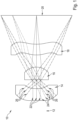
- FIG. 1 is a view illustrating a camera lens system 10 according to a first embodiment of the present invention.
- the object side 12 is on the left side related to the picture plane.
- a first lens 14 is shown on the left side, followed by a second lens 16 and a third lens 18.
- the image side 20 is on the right side related to the picture plane.
- FIG. 1 illustrates pathways 22, 24 and 26 of light rays through the lens system.
- the shown size ratios of the individual elements and the distances between the individual elements to each other are shown only by way of example and may differ in variants, not shown.
- an aperture stop is arranged between the first lens 14 and the second lens 16 (not shown).
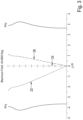
- FIG. 2 shows transverse ray aberrations for embodiment 1.
- FIG. 2 illustrates the different pathways of light for different wavelengths: first wavelength (486 nm) 22, second wavelength (587 nm) 24 and third wavelength (656 nm) 26.
- FIG. 3 shows lateral color aberration for embodiment 1.
- FIG. 3 illustrates the different pathways of light for different wavelengths: first wavelength (486 nm) 22, second wavelength (587 nm) 24 and third wavelength (656 nm) 26.
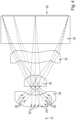
- FIG. 4 is a view illustrating a camera lens system according to a second embodiment of the present invention.
- the object side 12 is on the left side related to the picture plane.
- a first lens 28 is shown on the left side, followed by a second lens 30 and a third lens 32.
- the image side 20 is on the right side related to the picture plane.
- a standard cover glass 34 for a sensor.
- FIG. 4 illustrates different pathways 22, 24 and 26 for light rays through the lens system.
- the shown size ratios of the individual elements and the distances between the individual elements to each other are shown only by way of example and may differ in variants, not shown.
- an aperture stop is arranged between the first lens 14 and the second lens 16 (not shown).
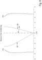
- FIG. 5 shows transverse ray aberrations for embodiment 2.
- FIG. 5 illustrates the different pathways of light for different wavelengths: first wavelength (486 nm) 22, second wavelength (587 nm) 24 and third wavelength (656 nm) 26.
- FIG. 6 shows lateral color aberration for embodiment 2.
- FIG. 6 illustrates the different pathways of light for different wavelengths: first wavelength (486 nm) 22, second wavelength (587 nm) 24 and third wavelength (656 nm) 26.
- FIG. 7 is a view illustrating a camera lens system according to a third embodiment of the present invention.
- the object side 12 is on the left side related to the picture plane.
- a first lens 36 is shown on the left side, followed by a second lens 38 and a third lens 40.
- the image side 20 is on the right side related to the picture plane.
- a standard cover glass 42 for a sensor.
- FIG. 7 illustrates the different pathways 22, 24 and 26 for light rays through the lens system.
- the shown size ratios of the individual elements and the distances between the individual elements to each other are shown only by way of example and may differ in variants, not shown.
- an aperture stop is arranged between the first lens 14 and the second lens 16 (not shown).
- FIG. 8 shows transverse ray aberrations for embodiment 3.
- FIG. 9 shows lateral color aberration for embodiment 3.
- FIG. 9 illustrates the different pathways of light for different wavelengths: first wavelength (486 nm) 22, second wavelength (587 nm) 24 and third wavelength (656 nm) 26.
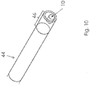
- FIG. 10 shows a schematic endoscope 44 with a camera lens system 10.
- the camera lens system 10 according to the present invention is preferably arranged such to be located in the distal tip 46 of the endoscope 44.
Landscapes
- Physics & Mathematics (AREA)
- General Physics & Mathematics (AREA)
- Optics & Photonics (AREA)
- Astronomy & Astrophysics (AREA)
- Lenses (AREA)
Description
- The invention relates to a camera lens system for an endoscope, method for producing a camera lens system and an endoscope.
- In the field of endoscopy, camera modules are required to fit in a small volume in order to minimize the invasiveness of an operation. Some technological processes like wafer level optics limit the variety of materials which can be implemented in the optical design of the system. Despite the limitation in available materials, good optical performance, particularly the color correction, is still required.
- Current solutions of endoscopic objective use at least two different materials to achieve sufficient performance and therefore results in a limitation concerning the chosen technology. For example technologies like wafer level optics are unlikely used for such cases and therefore cannot benefit from related advantages of improved production costs and an optimized size of the resulting system.
- The document
KR 2015/0033321 A1 - The document
US 6, 795, 253 B2 discloses an imaging lens. This imaging lens includes, in order from the object side, a positive meniscus first lens component with its convex lens surface on the object side, a positive meniscus second lens component with its convex lens surface on the image side and a negative third lens component with its concave lens surface on the image side. - [The document
US 7, 394, 602 B2 discloses an optical system for taking an image. This optical system comprises three lens elements with refractive power, from the object side to the image side: a first positive lens element having a convex front surface and a concave rear surface, and the front surface being aspheric, a negative plastic second lens element having a concave front surface and a convex rear surface, and the front and rear surfaces thereof being aspheric, a positive plastic third lens element having a convex front surface and a concave rear surface, the front and rear surfaces thereof being aspheric, and an aperture stop located between the first and second lens elements for controlling brightness of the optical system. - The document
US 7, 408, 725 B2 discloses a single focus lens. This single focus lens provides and includes, in order from an object side of the single focus lens, a first lens having positive power and having a convex surface on the object side, a second lens of a negative meniscus lens and having a concave surface of the object side on its paraxial axis and a third lens of an aspherical lens having a convex surface on the object side on its paraxial axis. - The document
US 7, 468, 847 B2 discloses an optical lens system for taking an image. This optical lens system comprises three lens elements with refractive power, from the object side to the image side: a first positive lens element having a convex surface on the object side and a concave surface on the image side, and at least one of the object side and image-side surfaces being aspheric, a negative plastic second lens element having a concave surface on the object side and a convex surface on the image side, and the object-side and image-side surfaces thereof being aspheric, a positive plastic third lens element having a convex surface on the object side and a concave surface on the image side, the object-side and image-side surfaces thereof being aspheric and an aperture stop located in front of the first lens element for controlling brightness of the optical lens system. A focal length of the second lens element is f2, a focal length of the optical lens system is f and they satisfy the relation: 0.1<|f/f2|<0.74. - The document
US 2013/ 0222675 A1 discloses an imaging lens and imaging device. This imaging lens includes a first lens, a second lens and a third lens arranged from an object side to an image plane side. The first lens has an object-side surface with a positive curvature radius. The second lens has an object-side surface and an image plane-side surface with negative curvature radii. The third lens has an object-side surface and an image plane-side surface with positive curvature radii. The object-side surface and the image plane-side surface of the third lens are respectively formed as an aspheric shape having an inflexion point. When the whole lens system has a focal length f, the first lens has a focal length f1, the second lens has a focal length f2, and the third lens has a focal length f3, the imaging lens satisfies the following conditional expressions: f1<f2 1.0<f1/f<1.5 0.7<f2/f3<1.2. - The document
US 2013/ 0222927 A1 discloses an imaging lens and imaging device. The imaging lens includes a first lens, a second lens and a third lens arranged from an object side to an image plane side. The first lens has an object-side surface having a positive curvature radius R1f and an image plane-side surface having a negative curvature radius R1r. The second lens has an object-side surface and an image plane-side surface with negative curvature radii. The third lens has an object-side surface and an image plane-side surface with positive curvature radii and formed as aspheric surfaces having inflexion points. When the whole lens system has a focal length f, the first lens has a focal length f1, the second lens has a focal length f2, and the third lens has a focal length f3, the imaging lens satisfies the following conditional expressions: f1 <f2<f3 1.0<f1/f<1.5 -0.02<R1f/R1r<0. - The document
US 2015/ 0029602 A1 discloses an imaging lens. The imaging lens includes a first lens having positive refractive power, a second lens having positive refractive power; and a third lens having negative refractive power, arranged in the order from an object side to an image plane side. The first lens and the third lens respectively have an object-side surface and an image plane-side surface whose curvature radii are both positive. The second lens has an image plane-side surface whose a curvature radius is negative. In addition, when the first lens has refractive power P1, the second lens has refractive power P2, the third lens has refractive power P3, the curvature radius of the image plane-side surface of the second lens is R2r, and the curvature radius of the object-side surface of the third lens is R3f, the imaging lens satisfies specific conditional expressions. - The document
US 2015/ 0029603 A1 discloses an imaging lens. The imaging lens includes a first lens having positive refractive power, a second lens having positive refractive power and a third lens having positive refractive power, arranged in the order from an object side to an image plane side. The first lens and the third lens have object-side surfaces and image plane-side surfaces, curvature radii of which are both positive. When the first lens has refractive power P1, the second lens has refractive power P2, the third lens has refractive power P3, the first lens has a focal length f1, and the third lens has a focal length f3, the imaging lens satisfies the following conditional expressions: 5.0<(P1+P3)/P2<8.5 6<f3/f1<30. - There is a desire for a steady improvement in the cost structure associated with such systems or parts of such systems and an effort to steadily reduce such systems regarding the overall size as well as the sizes of the single parts provided within the system.
- It is therefore an object of the presented invention to provide a camera lens system for an endoscope which provides a better cost structure and an improved performance concerning the size of the system.
- In a preferred embodiment of the invention it is provided that a camera lens system for an endoscope comprises the following components: At least three lenses, wherein the first lens, when starting from the object side, is a negative lens, the following lenses moving toward the image side are positive lenses, wherein the system comprises the following features: 45 < V1d < 75; | V1d - V2d | < 10; | V1d - V3d| < 10; | V2d - V3d| < 10; 1,45 < n1d < 1,75; |n1d - n2d | < 0,1; |n1d - n3d | < 0,1; |n2d - n3d | < 0,1; 0,4 < f < 0,7; -3 < f1/f < -2; 1,1 < f2/f < 1,3; 2,5 < f3/f < 3,5, wherein V1d, V2d and V3d are the Abbe numbers of the first, second and third lens respectively, n1d, n2d and n3d are the refractive indices of the first, second and third lens respectively, f is the focal length of the objective of the system, f1, f2 and f3 are the focal lengths of the first, second and third lens respectively. The invention with the presented components allows a cost-effective production, as well as an improved performance concerning the size of the system. In addition, the invention provides good optical performances, especially for the usage within the technical field of endoscopy. The camera lens system can also be a miniature camera system. Preferably a diagonal field of view ranges from 80 to 100 degrees, more preferably from 88 to 92 degrees.
- Further preferred embodiments of the invention will become apparent from the remaining features mentioned in the sub claims. In a preferred embodiment, said three lenses are formed from the same material. In a more preferred embodiment, said three lenses completely consist of the same material. Technologies like wafer level optics can therefore be used for manufacturing such an optical system resulting in improved production costs and an optimized size of the resulting system.
- According to a preferred embodiment of the invention, the three lenses are arranged along an optical axis which forms a straight line. It is further preferred that all three lenses are formed to be symmetrical to the rotation axis (optical axis). It is further preferred that no further components (changing the optical properties of the lens system) intervene said three lenses. It is further preferred that air (or another gas) fills the gaps between said lenses.
- According to a preferred embodiment of the invention, the first lens is formed such that the condition 50 < V1d < 65 is met. According to a preferred embodiment of the invention, the first lens is formed such that the condition 50 < V1d < 55 is met.
- According to a preferred embodiment of the invention, at least one of the following conditions is met: V1d - V2d | < 5; | V1d - V3d| < 5; | V2d - V3d| < 5.
- According to a preferred embodiment of the invention, the first lens is formed such that the
condition 1,45 < n1d < 1,65 is met. According to a preferred embodiment of the invention, the first lens is formed such that thecondition 1,50 < n1d < 1,55 is met. - According to a preferred embodiment of the invention, at least one of the following conditions is met: |n1d - n2d | < 0,05; |n1d - n3d | < 0,05; |n2d - n3d | < 0,05.
- According to a preferred embodiment of the invention, at least one of the following conditions is met: -2,75 < f1/f < -2,25; 1,15 < f2/f < 1,25; 2,75 < f3/f < 3,25.
- According to a preferred embodiment of the invention, at least one of the following conditions is met:
- 0,05 < thickness of first lens < 0,3
- 0,05 < thickness of second lens < 0,3
- 0,05 < thickness of third lens < 0,3.
- According to a preferred embodiment of the invention, at least one of the following conditions is met:
- 0,1 < thickness of first lens < 0,2
- 0,1 < thickness of second lens < 0,2
- 0,1 < thickness of third lens < 0,2.
- According to a preferred embodiment of the invention, at least one of the following conditions is met:
- 0,05 < distance between first lens and second lens < 0,3
- 0,05 < distance between second lens and third lens < 0,3
- According to a preferred embodiment of the invention, at least one of the following conditions is met:
- 0,1 < distance between first lens and second lens < 0,2
- 0,1 < distance between second lens and third lens < 0,2.
- According to a preferred embodiment of the invention, a distance between the third lens and a cover glass ranges between 0,1
und - If not defined otherwise in this application, the thickness of the lens(es) is measured along the rotational axis. If not defined otherwise in this application, a distance between lenses is measured along the rotational axis. If not defined otherwise, all values for length/ distance / thickness / radius / focal length or the like in this application are millimeters.
- In a further preferred embodiment of the invention, all three lenses are formed to be axially (rotationally) symmetrical. In a further preferred embodiment of the invention, all three lenses are positioned along a common axis (straight line) which represents the rotational axis of the system.
- In a further preferred embodiment of the invention, it is provided that the first lens, when starting from the object side, is a negative lens, the following lenses moving toward the image side are positive lenses, an aperture is positioned between the first an the second lenses and all lenses are made of the same material. By using the same material for all lenses, it is possible to use technologies like wafer level optics. This improves the advantages concerning costs and size, which are even better achieved. Current solutions of endoscopic objective use at least two different materials to achieve sufficient performance and are therefore more cost intensive and often cannot provide ideal sizes.
- In a further preferred embodiment of the invention, it is provided that the camera lens system utilizes a diagonal field of view of 90 degrees and an f-number of 5,0. This combination of features make sure that even better results are achievable when using the presented camera lens system.
- In a further preferred embodiment of the invention, it is provided that the system has a focal length of f = 0,5299 mm, the first lens is a meniscus lens, which is convex on the object side, and has a focal length of f1 = - 1,448 mm, the second lens is a meniscus lens, which is convex on the image side, and has a focal length of f2 = 0,6408 mm and the third lens is an aspheric lens, which is paraxial convex on the object side with a transition to being convex on the image side at a larger distance from the optical axis, and has a focal length of f3 = 1,665 mm. The resulting performance is shown in
figures 2 and3 for wavelengths 486, 587 and 656 nm. The good chromatic aberration correction, as shown infigure 2 , helps to achieve minimal ray aberrations across the field as shown infigure 3 . An overview of the lens description can also be seen below in table 2. This leads to relative focal lengths of f1/f = -2,733, f2/ f = 1,209 and f3/f = 3,141. In addition, an overview of the aspherical coefficients can be seen below in table 5. - In a further preferred embodiment of the invention, it is provided that the system has a focal length of f = 0,5310 mm, the first lens is a meniscus lens, which is convex on the object side, and has a focal length of f1 = - 1,397 mm, the second lens is a meniscus lens, which is convex on the image side, and has a focal length of f2 = 0,6400 mm and the third lens is an aspheric lens, which is paraxial convex on the object side with a transition to being convex on the image side at a larger distance from the optical axis, and has a focal length of f3 = 1,652 mm and the system comprises a standard cover glass for a sensor. The performance of this embodiment is shown in
figures 5 and6 for wavelengths 486, 587 and 656 nm. The well-corrected lateral color aberration shown infigure 6 helps to provide well-corrected transverse ray aberrations as shown infigure 5 . The focal lengths correspond to relative focal lengths of f1/f = -2,631, f2/f = 1,205 and f3/f = 3,112. An overview of the lens description can also be seen below in table 3. In addition, an overview of the aspherical coefficients can be seen below in table 6. The incorporated standard cover glass for a sensor provides a protection function for the lenses so that a robust and reliable system can be achieved. - In a further preferred embodiment of the invention, it is provided that the system has a focal length of f = 0,5821 mm, the first lens is a meniscus lens, which is convex on the object side, and has a focal length of f1 = - 1,423 mm, the second lens is a meniscus lens, which is convex on the image side, and has a focal length of f2 = 0,7132 mm and the third lens is an aspheric lens, which is paraxial convex on the object side with a transition to being convex on the image side at a larger distance from the optical axis, and has a focal length of f3 = 1,715 mm and the system comprises a standard cover glass for a sensor. These focal lengths correspond to relative focal lengths of f1/f = -2,445, f2/f = 1,225 and f3/f = 2,947. The performance is shown in
figure 8 and9 . An overview of the lens description can also be seen below in table 4. In addition, an overview of the aspherical coefficients can be seen below in table 7. The incorporated standard cover glass for a sensor provides a protection function for the lenses so that a robust and reliable system can be achieved. - In a further preferred embodiment of the invention, it is provided that the standard cover glass for a sensor is positioned between the third lens and the image side. In this way it is possible to provide good performance concerning the size of the presented system for various sensor configurations.
- In a further preferred embodiment of the invention, it is provided that a distance between the third lens and the standard cover glass for a sensor is bigger than a distance between the first lens and the second lens and/ or bigger than a distance between the second lens and the third lens.
- This additional space can be utilized in alignment processes to protect the lens and cover glass from damaging one another during assembly, or to adjust the optical parameters of the lens.
- In a further preferred embodiment of the invention, it is provided that a method for producing a camera lens system according to one of the preceding claims, comprises the following steps: providing a single material, producing at least three lenses, composing the at least three lenses so that the camera lens system is achieved, wherein the first lens, when starting from the object side, is a negative lens, the following lenses moving toward the image side are positive lenses, wherein the system comprises the following features: 45 < V1d < 75, | V1d - V2d | < 10, | V1d - V3d| < 10, | V2d - V3d| < 10, 1,45 < n1d < 1,75, |n1d - n2d | < 0,1, |n1d - n3d | < 0,1, |n2d - n3d | < 0,1, 0,4 < f < 0,7, -3 < f1/f < -2, 1,1 < f2/f < 1,3, 2,5 < f3/f < 3,5, wherein V1d, V2d and V3d are the Abbe numbers of the first, second and third lens respectively, n1d, n2d and n3d are the refractive indices of the first, second and third lens respectively, f is the focal length of the objective of the system, f1, f2 and f3 are the focal lengths of the first, second and third lens respectively. The advantages mentioned above apply in the same way to the presented method.
- Finally, in a further preferred embodiment of the invention, it is provided that an endoscope comprises at least one camera lens system according to one of the
claims 1 to 8. The advantages mentioned above apply in the same way to the presented endoscope. - A comparison of the present three preferred embodiments of the invention can be seen in table 1 below.
Table 1: Comparison of the three preferred embodiments Embodiment 1 Embodiment 2Embodiment 3 f 0,5299 mm 0,5310 mm 0,5821 mm f1 -1,448 mm -1,397 mm -1,423 mm f2 0,6408 mm 0,6400 mm 0,7132 mm f3 1,665 mm 1,652 mm 1,715 mm BFL 0,4027 mm 0,1320 mm 0,2400 mm f1/f -2,733 -2,631 -2,445 f2/f 1,209 1,205 1,225 f3/f 3,141 3,112 2,947 - [An overview of the parameter description of the three variations is given in Tables 2-7. The surface sag, z, is given by

Table 2: Lens description for embodiment 1 Surface Radius Thickness nd vd Object 0 5,5 1 4,10186207 0,16642131 1,507931 53,8125 2 0,61521869 0,11554587 Stop 0 0,01130894 4 -1.23571647 0,1725685 1,507931 53,8125 5 -0,26974506 0,17007553 6 0,30305173 0,15 1,507931 53,8125 7 0,39358507 0,40270978 Image Table 3: Lens description for embodiment 2 Surface Radius Thickness nd vd Object 0 5,5 1 14,683098 0,1714912 1,507931 53,8125 2 0,6742561 0,1142931 Stop 0 0,0113008 4 -1,28429569 0,1622698 1,507931 53,8125 5 -0,27046775 0,1735688 6 0,30306362 0,1500000 1,507931 53,8125 7 0,39524089 0,1319976 8 0 0,4000000 1,522385 64,1673 9 0 0,0100000 Image Table 4: Lens description for embodiment 3 Surface Radius Thickness nd vd Object 0 5,5 1 2,17177823 0,1536605 1,507931 53,8125 2 0,5294589 0,1193222 Stop 0 0,01243303 4 -0,80668211 0,18626317 1,507931 53,8125 5 -0,26944835 0,13432176 6 0,32401042 0,15 1,507931 53,8125 7 0,43537201 0,24 8 0 0,4 1,522385 64,1673 9 0 0,01 Image Table 5: Aspherical coefficients for embodiment 1 Surface k a1 a2 a3 a4 1 0 0 13,3903755 -52,5591927 332,350124 2 0 0 41,1446484 412,568112 -10251,8046 Stop 0 0 0 0 0 4 0 0 38,9443385 -20024,7566 2484306,2 5 0 0 -30,7014234 532,005084 -5708,68434 6 0 0 -30,6896162 170,058242 -1878,89654 7 0 0 -18,2913389 79,7524751 -477,709166 Table 6: Aspherical coefficients for embodiment 2 Surface k a1 a2 a3 a4 1 0 0 13,4287567 -55,6713333 323,46834 2 0 0 39,9953966 429,854771 -13265,3025 Stop 0 0 0 0 0 4 0 0 38,8577367 -20077,6864 2463636,63 5 0 0 -31,1690192 522,247905 -4934,95751 6 0 0 -29,8973214 171,010398 -1945,79763 7 0 0 -18,0478993 80,7056578 -483,119338 8 0 0 0 0 0 9 0 0 0 0 0 Table 7: Aspherical coefficients for embodiment 3 Surface k a1 a2 a3 a4 1 0 0 12,3968892 -29,7635134 247,550513 2 0 0 35,2512836 804,946509 -14099,6553 Stop 0 0 0 0 0 4 0 0 34,9167636 -16776,9258 1842848,37 5 0 0 -28,3332338 392,547952 -3936,98259 6 0 0 -29,7061968 209,299165 -1682,57956 7 0 0 -16,1613339 74,4222303 -420,842149 8 0 0 0 0 0 9 0 0 0 0 0 - The various embodiments of the invention mentioned in this application are, unless otherwise stated in the individual case, advantageously combinable with each other.
- The invention will be explained below in embodiments with reference to the accompanying drawings. In these drawings,
- FIG. 1
- is a view illustrating a camera lens system according to a first embodiment of the present invention;
- FIG 2
- shows transverse ray aberrations for
embodiment 1; - FIG. 3
- shows lateral color aberration for
embodiment 1; - FIG. 4
- is a view illustrating a camera lens system according to a second embodiment of the present invention;
- FIG 5
- shows transverse ray aberrations for
embodiment 2; - FIG. 6
- shows lateral color aberration for
embodiment 2; - FIG. 7
- is a view illustrating a camera lens system according to a third embodiment of the present invention;
- FIG 8
- shows transverse ray aberrations for
embodiment 3; - FIG. 9
- shows lateral color aberration for
embodiment 3; - FIG. 10
- shows a schematic endoscope with a camera lens system.
-
FIG. 1 is a view illustrating acamera lens system 10 according to a first embodiment of the present invention. Theobject side 12 is on the left side related to the picture plane. Afirst lens 14 is shown on the left side, followed by asecond lens 16 and athird lens 18. Theimage side 20 is on the right side related to the picture plane. For thelenses FIG. 1 illustratespathways first lens 14 and the second lens 16 (not shown). -
FIG. 2 shows transverse ray aberrations forembodiment 1. In addition,FIG. 2 illustrates the different pathways of light for different wavelengths: first wavelength (486 nm) 22, second wavelength (587 nm) 24 and third wavelength (656 nm) 26. -
FIG. 3 shows lateral color aberration forembodiment 1. In addition,FIG. 3 illustrates the different pathways of light for different wavelengths: first wavelength (486 nm) 22, second wavelength (587 nm) 24 and third wavelength (656 nm) 26. -
FIG. 4 is a view illustrating a camera lens system according to a second embodiment of the present invention. Theobject side 12 is on the left side related to the picture plane. Afirst lens 28 is shown on the left side, followed by asecond lens 30 and athird lens 32. Theimage side 20 is on the right side related to the picture plane. Between thethird lens 32 and theimage side 20 is shown astandard cover glass 34 for a sensor. For thelenses FIG. 4 illustratesdifferent pathways first lens 14 and the second lens 16 (not shown). -
FIG. 5 shows transverse ray aberrations forembodiment 2. In addition,FIG. 5 illustrates the different pathways of light for different wavelengths: first wavelength (486 nm) 22, second wavelength (587 nm) 24 and third wavelength (656 nm) 26. -
FIG. 6 shows lateral color aberration forembodiment 2. In addition,FIG. 6 illustrates the different pathways of light for different wavelengths: first wavelength (486 nm) 22, second wavelength (587 nm) 24 and third wavelength (656 nm) 26. -
FIG. 7 is a view illustrating a camera lens system according to a third embodiment of the present invention. Theobject side 12 is on the left side related to the picture plane. Afirst lens 36 is shown on the left side, followed by asecond lens 38 and athird lens 40. Theimage side 20 is on the right side related to the picture plane. Between thethird lens 40 and theimage side 20 is shown astandard cover glass 42 for a sensor. For thelenses FIG. 7 illustrates thedifferent pathways first lens 14 and the second lens 16 (not shown). -
FIG. 8 shows transverse ray aberrations forembodiment 3. -
FIG. 9 shows lateral color aberration forembodiment 3. In addition,FIG. 9 illustrates the different pathways of light for different wavelengths: first wavelength (486 nm) 22, second wavelength (587 nm) 24 and third wavelength (656 nm) 26. -
FIG. 10 shows aschematic endoscope 44 with acamera lens system 10. As can be see fromFig. 10 , thecamera lens system 10 according to the present invention is preferably arranged such to be located in thedistal tip 46 of theendoscope 44. -
- 10
- camera lens system
- 12
- object side
- 14
- first lens
- 16
- second lens
- 18
- third lens
- 20
- image side
- 22
- first wavelength
- 24
- second wavelength
- 26
- third wavelength
- 28
- first lens
- 30
- second lens
- 32
- third lens
- 34
- standard cover glass
- 36
- first lens
- 38
- second lens
- 40
- third lens
- 42
- standard cover glass
- 44
- endoscope
- 46
- distal tip of endoscope
Claims (13)
- A camera lens system (10) for an endoscope (44) comprising at least three lenses, wherein the first lens (14, 28, 36), when starting from the object side, is a negative lens, all following lenses moving toward the image side (20) are positive lenses, characterized in that the system (10) comprises the following features:a) 45 < V1d < 75;b) | V1d - V2d | < 10;c) | V1d - V3d | < 10;d) | V2d - V3d | < 10;e) 1,45 < n1d < 1,75;f) | n1d - n2d | < 0,1;g) | n1d - n3d | < 0,1;h) | n2d - n3d | < 0,1;i) 0,4 mm < f < 0,7 mm;j) -3 < f1/f < -2;k) 1,1 < f2/f < 1,3;l) 2,5 < f3/f < 3,5,wherein V1d, V2d and V3d are the Abbe numbers of the first, second and third lens respectively, n1d, n2d and n3d are the refractive indices of the first, second and third lens respectively, f is the focal length of the objective of the system (10), f1, f2 and f3 are the focal lengths in mm of the first, second and third lens respectively.
- A camera lens system (10) according to claim 1, wherein at least two of said three lenses are formed of the same material.
- A camera lens system (10) according to claim 2, wherein said three lenses are formed of the same material.
- A camera lens system (10) according to any of the preceding claims, wherein the first lens (14, 28, 36), when starting from the object side (12), is a negative lens, the following lenses moving toward the image side (20) are positive lenses, an aperture is positioned between the first (14, 28, 36) an the second lenses (16, 30, 38).
- A camera lens system (10) to one of the preceding claims, wherein the lenses are formed such that a diagonal field of view ranges from 80 to 100 degrees.
- A camera lens system (10) according to one of the preceding claims, wherein the system (10) has a focal length of f = 0,5299 mm, the first lens (14) is a meniscus lens, which is convex on the object side (12), and has a focal length of f1 = - 1,448 mm, the second lens (16) is a meniscus lens, which is convex on the image side (20), and has a focal length of f2 = 0,6408 mm and the third lens (18) is an aspheric lens, which is paraxial convex on the object side (12) with a transition to being convex on the image side (20) at a larger distance from the optical axis, and has a focal length of f3 = 1,665 mm.
- A camera lens system (10) according to one of the claims 1 to 5, wherein the system (10) has a focal length of f = 0,5310 mm, the first lens (28) is a meniscus lens, which is convex on the object side (12), and has a focal length of f1 = - 1,397 mm, the second lens (30) is a meniscus lens, which is convex on the image side, and has a focal length of f2 = 0,6400 mm and the third lens (32) is an aspheric lens, which is paraxial convex on the object side (12) with a transition to being convex on the image side (20) at a larger distance from the optical axis, and has a focal length of f3 = 1,652 mm and the system (10) comprises a standard cover glass (34) for a sensor.
- A camera lens system (10) according to one of the claims 1 to 5, wherein the system (10) has a focal length of f = 0,5821 mm, the first lens (36) is a meniscus lens, which is convex on the object side (12), and has a focal length of f1 = - 1,423 mm, the second lens (38) is a meniscus lens, which is convex on the image side, and has a focal length of f2 = 0,7132 mm and the third lens (40) is an aspheric lens, which is paraxial convex on the object side (12) with a transition to being convex on the image side (20) at a larger distance from the optical axis, and has a focal length of f3 = 1,715 mm and the system (10) comprises a standard cover glass (42) for a sensor.
- A camera lens system (10) according to claims 7 and 8, wherein the standard cover glass (34, 42) for a sensor is positioned between the third lens (32, 40) and the image side (20).
- A camera lens system (10) according to claim 8 or 9, wherein a distance between the third lens (32, 40) and the standard cover glass (34, 42) for a sensor is bigger than a distance between the first lens (28, 36) and the second lens (30, 38) and/ or bigger than a distance between the second lens (30, 38) and the third lens (32, 40).
- A camera lens system (10) according to any of claims 5 to 10, wherein the lenses are formed such that a diagonal field of view is 90 degrees.
- Method for producing a camera lens system (10) according to one of the preceding claims, comprising the following steps:producing at least three lenses;composing the at least three lenses so that the camera lens system (10) is achieved, wherein the first lens (14, 28, 36), when starting from the object side (12), is a negative lens, all following lenses moving toward the image side (20) are positive lenses, characterized in that the system (10) comprises the following features:a) 45 < V1d < 75;b) | V1d - V2d | < 10;c) | V1d -V3d | < 10;d) | V2d - V3d | < 10;e) 1,45 < n1d < 1,75;f) | n1d - n2d | < 0,1;g) | n1d - n3d | < 0,1;h) | n2d - n3d | < 0,1;i) 0,4 mm < f < 0,7 mm;j) -3 < f1/f < -2;k) 1,1 < f2/f < 1,3;l) 2,5 < f3/f < 3,5,wherein V1d, V2d and V3d are the Abbe numbers of the first, second and third lens respectively, n1d, n2d and n3d are the refractive indices of the first, second and third lens respectively, f is the focal length of the objective of the system, f1, f2 and f3 are the focal lengths in mm of the first, second and third lens respectively.
- Endoscope (44) comprising at least one camera lens system (10) according to one of the claims 1 to 11.
Priority Applications (2)
| Application Number | Priority Date | Filing Date | Title |
|---|---|---|---|
| EP18189261.3A EP3611552B1 (en) | 2018-08-16 | 2018-08-16 | Camera lens system for an endoscope, method for producing a camera lens system and an endoscope |
| US16/507,618 US11054630B2 (en) | 2018-08-16 | 2019-07-10 | Camera lens system for an endoscope, method for producing a camera lens system and an endoscope |
Applications Claiming Priority (1)
| Application Number | Priority Date | Filing Date | Title |
|---|---|---|---|
| EP18189261.3A EP3611552B1 (en) | 2018-08-16 | 2018-08-16 | Camera lens system for an endoscope, method for producing a camera lens system and an endoscope |
Publications (2)
| Publication Number | Publication Date |
|---|---|
| EP3611552A1 EP3611552A1 (en) | 2020-02-19 |
| EP3611552B1 true EP3611552B1 (en) | 2023-03-08 |
Family
ID=63294053
Family Applications (1)
| Application Number | Title | Priority Date | Filing Date |
|---|---|---|---|
| EP18189261.3A Active EP3611552B1 (en) | 2018-08-16 | 2018-08-16 | Camera lens system for an endoscope, method for producing a camera lens system and an endoscope |
Country Status (2)
| Country | Link |
|---|---|
| US (1) | US11054630B2 (en) |
| EP (1) | EP3611552B1 (en) |
Families Citing this family (9)
| Publication number | Priority date | Publication date | Assignee | Title |
|---|---|---|---|---|
| CN112946875B (en) * | 2021-03-26 | 2025-06-24 | 复旦大学附属中山医院 | Infrared endoscope eyepiece optical system for imaging blood flow |
| CN113238341B (en) * | 2021-05-09 | 2022-08-02 | 深圳市晶钛光学股份有限公司 | 3 miniature super wide angle lens of piece formula and electronic equipment |
| US11832791B2 (en) | 2021-09-17 | 2023-12-05 | Altek Biotechnology Corporation | Optical imaging lens assembly and endoscopic optical device |
| CN113820827A (en) * | 2021-09-28 | 2021-12-21 | 玉晶光电(厦门)有限公司 | Optical imaging lens |
| CN114280762B (en) * | 2022-03-04 | 2022-05-27 | 精微致远医疗科技(武汉)有限公司 | Be applied to miniature camera lens of pancreaticobiliary duct's miniature probe |
| CN114779433B (en) * | 2022-03-10 | 2023-09-15 | 东莞晶彩光学有限公司 | Short-distance wide-viewing angle imaging lens group |
| CN116609936B (en) * | 2023-05-31 | 2026-02-06 | 广东旭业光电科技股份有限公司 | Endoscope optical imaging lens and electronic equipment |
| CN119024472B (en) * | 2024-10-30 | 2025-04-15 | 新菲光通信技术有限公司 | Multifaceted optical lens, lens array, optical module and optical communication equipment |
| CN120255139B (en) * | 2025-06-04 | 2025-08-29 | 华中科技大学 | Miniature endoscopic microscope objective |
Family Cites Families (22)
| Publication number | Priority date | Publication date | Assignee | Title |
|---|---|---|---|---|
| US5175650A (en) * | 1989-05-09 | 1992-12-29 | Olympus Optical Co., Ltd. | Objective lens system for endoscopes |
| KR20020035588A (en) * | 1999-09-08 | 2002-05-11 | 기시모토 마사도시 | Image pickup optical system for endoscope |
| JP3567327B2 (en) | 2002-05-08 | 2004-09-22 | 富士写真光機株式会社 | Imaging lens |
| JP4804856B2 (en) | 2005-09-29 | 2011-11-02 | 富士フイルム株式会社 | Single focus lens |
| JP4815319B2 (en) * | 2006-09-29 | 2011-11-16 | 富士フイルム株式会社 | Imaging lens and camera device provided with the same |
| TWI315417B (en) | 2006-10-30 | 2009-10-01 | Largan Precision Co Ltd | Optical system for taking image |
| TWI316614B (en) | 2006-12-25 | 2009-11-01 | Largan Precision Co Ltd | Optical lens system for taking image |
| JP4920572B2 (en) * | 2007-12-21 | 2012-04-18 | オリンパスメディカルシステムズ株式会社 | Endoscope objective lens |
| CN102687054B (en) * | 2009-12-14 | 2014-04-09 | 堂智 | Wide-angle lens and system equipped with wide-angle lens |
| JP5585663B2 (en) * | 2010-12-28 | 2014-09-10 | コニカミノルタ株式会社 | Wide-angle lens, imaging optical device and digital equipment |
| JP5861933B2 (en) | 2012-02-28 | 2016-02-16 | 株式会社オプトロジック | Imaging lens |
| JP5861932B2 (en) | 2012-02-28 | 2016-02-16 | 株式会社オプトロジック | Imaging lens |
| JP6171242B2 (en) | 2013-07-29 | 2017-08-02 | 株式会社オプトロジック | Imaging lens |
| JP6146741B2 (en) | 2013-07-29 | 2017-06-14 | 株式会社オプトロジック | Imaging lens |
| WO2015025843A1 (en) * | 2013-08-22 | 2015-02-26 | オリンパスメディカルシステムズ株式会社 | Endoscope objective optical system |
| JP2015060019A (en) * | 2013-09-18 | 2015-03-30 | 富士フイルム株式会社 | Endoscope objective lens and endoscope |
| KR101535086B1 (en) | 2013-09-24 | 2015-07-09 | 주식회사 세코닉스 | Photographing wide angle lens system corrected distortion |
| WO2017068726A1 (en) * | 2015-10-23 | 2017-04-27 | オリンパス株式会社 | Imaging device and optical device provided with same |
| US9798115B1 (en) * | 2016-04-26 | 2017-10-24 | Omnivision Technologies, Inc. | Compact three-surface wafer-level lens systems |
| US10288854B2 (en) * | 2016-11-30 | 2019-05-14 | Omnivision Technologies, Inc. | Athermal compound lens |
| JP2018180422A (en) * | 2017-04-20 | 2018-11-15 | オリンパス株式会社 | Imaging apparatus |
| JP6664853B2 (en) * | 2017-06-15 | 2020-03-13 | カンタツ株式会社 | Imaging lens |
-
2018
- 2018-08-16 EP EP18189261.3A patent/EP3611552B1/en active Active
-
2019
- 2019-07-10 US US16/507,618 patent/US11054630B2/en active Active
Also Published As
| Publication number | Publication date |
|---|---|
| US20200057296A1 (en) | 2020-02-20 |
| US11054630B2 (en) | 2021-07-06 |
| EP3611552A1 (en) | 2020-02-19 |
Similar Documents
| Publication | Publication Date | Title |
|---|---|---|
| EP3611552B1 (en) | Camera lens system for an endoscope, method for producing a camera lens system and an endoscope | |
| US7502181B2 (en) | Imaging lens | |
| CN113640951A (en) | Camera lens | |
| EP3531180B1 (en) | Imaging lens and imaging device having the same | |
| EP1906223A2 (en) | Wide-angle compact imaging lens with three single lenses | |
| CN113960773A (en) | Optical imaging lens and imaging apparatus | |
| JP2003270530A (en) | Wide angle lens having aspheric synthetic resin lens | |
| JP2009092798A (en) | Imaging lens and imaging device | |
| US7046454B2 (en) | Two-group zoom lens | |
| US11609408B2 (en) | Optical imaging lens | |
| JP2009145809A (en) | Image pickup lens and image pickup apparatus | |
| EP3252522B1 (en) | Lens apparatus and an image pickup apparatus including same | |
| CN107203028A (en) | Optical imaging system | |
| CN101131465A (en) | Retrofocus type of zoom lens having three lens groups | |
| WO2001025833A1 (en) | Zoom lens and video camera comprising the same | |
| JP2005345919A (en) | Imaging lens | |
| CN113640945A (en) | Camera lens | |
| WO2019019530A1 (en) | Optical imaging camera | |
| US6724547B2 (en) | Single-focus lens | |
| CN114994862A (en) | Camera lens | |
| CN114051590B (en) | Imaging lens and imaging device | |
| JP5806737B2 (en) | Imaging lens and imaging apparatus | |
| CN107076965A (en) | Endoscope objective optical system | |
| JP5778280B2 (en) | Imaging lens and imaging apparatus | |
| US20040263997A1 (en) | Small lightweight zoom lens |
Legal Events
| Date | Code | Title | Description |
|---|---|---|---|
| PUAI | Public reference made under article 153(3) epc to a published international application that has entered the european phase |
Free format text: ORIGINAL CODE: 0009012 |
|
| STAA | Information on the status of an ep patent application or granted ep patent |
Free format text: STATUS: REQUEST FOR EXAMINATION WAS MADE |
|
| 17P | Request for examination filed |
Effective date: 20190605 |
|
| AK | Designated contracting states |
Kind code of ref document: A1 Designated state(s): AL AT BE BG CH CY CZ DE DK EE ES FI FR GB GR HR HU IE IS IT LI LT LU LV MC MK MT NL NO PL PT RO RS SE SI SK SM TR |
|
| AX | Request for extension of the european patent |
Extension state: BA ME |
|
| RIC1 | Information provided on ipc code assigned before grant |
Ipc: G02B 23/24 20060101AFI20220812BHEP |
|
| GRAP | Despatch of communication of intention to grant a patent |
Free format text: ORIGINAL CODE: EPIDOSNIGR1 |
|
| STAA | Information on the status of an ep patent application or granted ep patent |
Free format text: STATUS: GRANT OF PATENT IS INTENDED |
|
| INTG | Intention to grant announced |
Effective date: 20220926 |
|
| GRAS | Grant fee paid |
Free format text: ORIGINAL CODE: EPIDOSNIGR3 |
|
| GRAA | (expected) grant |
Free format text: ORIGINAL CODE: 0009210 |
|
| STAA | Information on the status of an ep patent application or granted ep patent |
Free format text: STATUS: THE PATENT HAS BEEN GRANTED |
|
| AK | Designated contracting states |
Kind code of ref document: B1 Designated state(s): AL AT BE BG CH CY CZ DE DK EE ES FI FR GB GR HR HU IE IS IT LI LT LU LV MC MK MT NL NO PL PT RO RS SE SI SK SM TR |
|
| REG | Reference to a national code |
Ref country code: CH Ref legal event code: EP Ref country code: AT Ref legal event code: REF Ref document number: 1552975 Country of ref document: AT Kind code of ref document: T Effective date: 20230315 |
|
| REG | Reference to a national code |
Ref country code: IE Ref legal event code: FG4D |
|
| REG | Reference to a national code |
Ref country code: DE Ref legal event code: R096 Ref document number: 602018046891 Country of ref document: DE |
|
| REG | Reference to a national code |
Ref country code: LT Ref legal event code: MG9D |
|
| REG | Reference to a national code |
Ref country code: NL Ref legal event code: MP Effective date: 20230308 |
|
| PG25 | Lapsed in a contracting state [announced via postgrant information from national office to epo] |
Ref country code: RS Free format text: LAPSE BECAUSE OF FAILURE TO SUBMIT A TRANSLATION OF THE DESCRIPTION OR TO PAY THE FEE WITHIN THE PRESCRIBED TIME-LIMIT Effective date: 20230308 Ref country code: NO Free format text: LAPSE BECAUSE OF FAILURE TO SUBMIT A TRANSLATION OF THE DESCRIPTION OR TO PAY THE FEE WITHIN THE PRESCRIBED TIME-LIMIT Effective date: 20230608 Ref country code: LV Free format text: LAPSE BECAUSE OF FAILURE TO SUBMIT A TRANSLATION OF THE DESCRIPTION OR TO PAY THE FEE WITHIN THE PRESCRIBED TIME-LIMIT Effective date: 20230308 Ref country code: LT Free format text: LAPSE BECAUSE OF FAILURE TO SUBMIT A TRANSLATION OF THE DESCRIPTION OR TO PAY THE FEE WITHIN THE PRESCRIBED TIME-LIMIT Effective date: 20230308 Ref country code: HR Free format text: LAPSE BECAUSE OF FAILURE TO SUBMIT A TRANSLATION OF THE DESCRIPTION OR TO PAY THE FEE WITHIN THE PRESCRIBED TIME-LIMIT Effective date: 20230308 Ref country code: ES Free format text: LAPSE BECAUSE OF FAILURE TO SUBMIT A TRANSLATION OF THE DESCRIPTION OR TO PAY THE FEE WITHIN THE PRESCRIBED TIME-LIMIT Effective date: 20230308 |
|
| REG | Reference to a national code |
Ref country code: AT Ref legal event code: MK05 Ref document number: 1552975 Country of ref document: AT Kind code of ref document: T Effective date: 20230308 |
|
| PG25 | Lapsed in a contracting state [announced via postgrant information from national office to epo] |
Ref country code: SE Free format text: LAPSE BECAUSE OF FAILURE TO SUBMIT A TRANSLATION OF THE DESCRIPTION OR TO PAY THE FEE WITHIN THE PRESCRIBED TIME-LIMIT Effective date: 20230308 Ref country code: NL Free format text: LAPSE BECAUSE OF FAILURE TO SUBMIT A TRANSLATION OF THE DESCRIPTION OR TO PAY THE FEE WITHIN THE PRESCRIBED TIME-LIMIT Effective date: 20230308 Ref country code: GR Free format text: LAPSE BECAUSE OF FAILURE TO SUBMIT A TRANSLATION OF THE DESCRIPTION OR TO PAY THE FEE WITHIN THE PRESCRIBED TIME-LIMIT Effective date: 20230609 Ref country code: FI Free format text: LAPSE BECAUSE OF FAILURE TO SUBMIT A TRANSLATION OF THE DESCRIPTION OR TO PAY THE FEE WITHIN THE PRESCRIBED TIME-LIMIT Effective date: 20230308 |
|
| PG25 | Lapsed in a contracting state [announced via postgrant information from national office to epo] |
Ref country code: SM Free format text: LAPSE BECAUSE OF FAILURE TO SUBMIT A TRANSLATION OF THE DESCRIPTION OR TO PAY THE FEE WITHIN THE PRESCRIBED TIME-LIMIT Effective date: 20230308 Ref country code: RO Free format text: LAPSE BECAUSE OF FAILURE TO SUBMIT A TRANSLATION OF THE DESCRIPTION OR TO PAY THE FEE WITHIN THE PRESCRIBED TIME-LIMIT Effective date: 20230308 Ref country code: PT Free format text: LAPSE BECAUSE OF FAILURE TO SUBMIT A TRANSLATION OF THE DESCRIPTION OR TO PAY THE FEE WITHIN THE PRESCRIBED TIME-LIMIT Effective date: 20230710 Ref country code: EE Free format text: LAPSE BECAUSE OF FAILURE TO SUBMIT A TRANSLATION OF THE DESCRIPTION OR TO PAY THE FEE WITHIN THE PRESCRIBED TIME-LIMIT Effective date: 20230308 Ref country code: CZ Free format text: LAPSE BECAUSE OF FAILURE TO SUBMIT A TRANSLATION OF THE DESCRIPTION OR TO PAY THE FEE WITHIN THE PRESCRIBED TIME-LIMIT Effective date: 20230308 Ref country code: AT Free format text: LAPSE BECAUSE OF FAILURE TO SUBMIT A TRANSLATION OF THE DESCRIPTION OR TO PAY THE FEE WITHIN THE PRESCRIBED TIME-LIMIT Effective date: 20230308 |
|
| PG25 | Lapsed in a contracting state [announced via postgrant information from national office to epo] |
Ref country code: SK Free format text: LAPSE BECAUSE OF FAILURE TO SUBMIT A TRANSLATION OF THE DESCRIPTION OR TO PAY THE FEE WITHIN THE PRESCRIBED TIME-LIMIT Effective date: 20230308 Ref country code: PL Free format text: LAPSE BECAUSE OF FAILURE TO SUBMIT A TRANSLATION OF THE DESCRIPTION OR TO PAY THE FEE WITHIN THE PRESCRIBED TIME-LIMIT Effective date: 20230308 Ref country code: IS Free format text: LAPSE BECAUSE OF FAILURE TO SUBMIT A TRANSLATION OF THE DESCRIPTION OR TO PAY THE FEE WITHIN THE PRESCRIBED TIME-LIMIT Effective date: 20230708 |
|
| REG | Reference to a national code |
Ref country code: DE Ref legal event code: R097 Ref document number: 602018046891 Country of ref document: DE |
|
| PLBE | No opposition filed within time limit |
Free format text: ORIGINAL CODE: 0009261 |
|
| STAA | Information on the status of an ep patent application or granted ep patent |
Free format text: STATUS: NO OPPOSITION FILED WITHIN TIME LIMIT |
|
| PG25 | Lapsed in a contracting state [announced via postgrant information from national office to epo] |
Ref country code: SI Free format text: LAPSE BECAUSE OF FAILURE TO SUBMIT A TRANSLATION OF THE DESCRIPTION OR TO PAY THE FEE WITHIN THE PRESCRIBED TIME-LIMIT Effective date: 20230308 Ref country code: DK Free format text: LAPSE BECAUSE OF FAILURE TO SUBMIT A TRANSLATION OF THE DESCRIPTION OR TO PAY THE FEE WITHIN THE PRESCRIBED TIME-LIMIT Effective date: 20230308 |
|
| 26N | No opposition filed |
Effective date: 20231211 |
|
| PG25 | Lapsed in a contracting state [announced via postgrant information from national office to epo] |
Ref country code: MC Free format text: LAPSE BECAUSE OF FAILURE TO SUBMIT A TRANSLATION OF THE DESCRIPTION OR TO PAY THE FEE WITHIN THE PRESCRIBED TIME-LIMIT Effective date: 20230308 |
|
| REG | Reference to a national code |
Ref country code: CH Ref legal event code: PL |
|
| PG25 | Lapsed in a contracting state [announced via postgrant information from national office to epo] |
Ref country code: MC Free format text: LAPSE BECAUSE OF FAILURE TO SUBMIT A TRANSLATION OF THE DESCRIPTION OR TO PAY THE FEE WITHIN THE PRESCRIBED TIME-LIMIT Effective date: 20230308 |
|
| PG25 | Lapsed in a contracting state [announced via postgrant information from national office to epo] |
Ref country code: LU Free format text: LAPSE BECAUSE OF NON-PAYMENT OF DUE FEES Effective date: 20230816 |
|
| GBPC | Gb: european patent ceased through non-payment of renewal fee |
Effective date: 20230816 |
|
| PG25 | Lapsed in a contracting state [announced via postgrant information from national office to epo] |
Ref country code: LU Free format text: LAPSE BECAUSE OF NON-PAYMENT OF DUE FEES Effective date: 20230816 Ref country code: CH Free format text: LAPSE BECAUSE OF NON-PAYMENT OF DUE FEES Effective date: 20230831 |
|
| REG | Reference to a national code |
Ref country code: BE Ref legal event code: MM Effective date: 20230831 |
|
| REG | Reference to a national code |
Ref country code: IE Ref legal event code: MM4A |
|
| PG25 | Lapsed in a contracting state [announced via postgrant information from national office to epo] |
Ref country code: IT Free format text: LAPSE BECAUSE OF FAILURE TO SUBMIT A TRANSLATION OF THE DESCRIPTION OR TO PAY THE FEE WITHIN THE PRESCRIBED TIME-LIMIT Effective date: 20230308 |
|
| PG25 | Lapsed in a contracting state [announced via postgrant information from national office to epo] |
Ref country code: IE Free format text: LAPSE BECAUSE OF NON-PAYMENT OF DUE FEES Effective date: 20230816 |
|
| PG25 | Lapsed in a contracting state [announced via postgrant information from national office to epo] |
Ref country code: GB Free format text: LAPSE BECAUSE OF NON-PAYMENT OF DUE FEES Effective date: 20230816 |
|
| PG25 | Lapsed in a contracting state [announced via postgrant information from national office to epo] |
Ref country code: IE Free format text: LAPSE BECAUSE OF NON-PAYMENT OF DUE FEES Effective date: 20230816 Ref country code: GB Free format text: LAPSE BECAUSE OF NON-PAYMENT OF DUE FEES Effective date: 20230816 Ref country code: FR Free format text: LAPSE BECAUSE OF NON-PAYMENT OF DUE FEES Effective date: 20230831 |
|
| PG25 | Lapsed in a contracting state [announced via postgrant information from national office to epo] |
Ref country code: BE Free format text: LAPSE BECAUSE OF NON-PAYMENT OF DUE FEES Effective date: 20230831 |
|
| PG25 | Lapsed in a contracting state [announced via postgrant information from national office to epo] |
Ref country code: BG Free format text: LAPSE BECAUSE OF FAILURE TO SUBMIT A TRANSLATION OF THE DESCRIPTION OR TO PAY THE FEE WITHIN THE PRESCRIBED TIME-LIMIT Effective date: 20230308 |
|
| PG25 | Lapsed in a contracting state [announced via postgrant information from national office to epo] |
Ref country code: BG Free format text: LAPSE BECAUSE OF FAILURE TO SUBMIT A TRANSLATION OF THE DESCRIPTION OR TO PAY THE FEE WITHIN THE PRESCRIBED TIME-LIMIT Effective date: 20230308 |
|
| PG25 | Lapsed in a contracting state [announced via postgrant information from national office to epo] |
Ref country code: CY Free format text: LAPSE BECAUSE OF FAILURE TO SUBMIT A TRANSLATION OF THE DESCRIPTION OR TO PAY THE FEE WITHIN THE PRESCRIBED TIME-LIMIT; INVALID AB INITIO Effective date: 20180816 |
|
| PG25 | Lapsed in a contracting state [announced via postgrant information from national office to epo] |
Ref country code: HU Free format text: LAPSE BECAUSE OF FAILURE TO SUBMIT A TRANSLATION OF THE DESCRIPTION OR TO PAY THE FEE WITHIN THE PRESCRIBED TIME-LIMIT; INVALID AB INITIO Effective date: 20180816 |
|
| PGFP | Annual fee paid to national office [announced via postgrant information from national office to epo] |
Ref country code: DE Payment date: 20250819 Year of fee payment: 8 |
|
| PG25 | Lapsed in a contracting state [announced via postgrant information from national office to epo] |
Ref country code: TR Free format text: LAPSE BECAUSE OF FAILURE TO SUBMIT A TRANSLATION OF THE DESCRIPTION OR TO PAY THE FEE WITHIN THE PRESCRIBED TIME-LIMIT Effective date: 20230308 |