EP3611399A1 - Silk hat-type strain wave gear device - Google Patents
Silk hat-type strain wave gear device Download PDFInfo
- Publication number
- EP3611399A1 EP3611399A1 EP17905051.3A EP17905051A EP3611399A1 EP 3611399 A1 EP3611399 A1 EP 3611399A1 EP 17905051 A EP17905051 A EP 17905051A EP 3611399 A1 EP3611399 A1 EP 3611399A1
- Authority
- EP
- European Patent Office
- Prior art keywords
- bearing
- gap part
- gear
- seal
- race
- Prior art date
- Legal status (The legal status is an assumption and is not a legal conclusion. Google has not performed a legal analysis and makes no representation as to the accuracy of the status listed.)
- Granted
Links
Images


Classifications
-
- F—MECHANICAL ENGINEERING; LIGHTING; HEATING; WEAPONS; BLASTING
- F16—ENGINEERING ELEMENTS AND UNITS; GENERAL MEASURES FOR PRODUCING AND MAINTAINING EFFECTIVE FUNCTIONING OF MACHINES OR INSTALLATIONS; THERMAL INSULATION IN GENERAL
- F16H—GEARING
- F16H57/00—General details of gearing
- F16H57/04—Features relating to lubrication or cooling or heating
- F16H57/0467—Elements of gearings to be lubricated, cooled or heated
- F16H57/0469—Bearings or seals
-
- F—MECHANICAL ENGINEERING; LIGHTING; HEATING; WEAPONS; BLASTING
- F01—MACHINES OR ENGINES IN GENERAL; ENGINE PLANTS IN GENERAL; STEAM ENGINES
- F01D—NON-POSITIVE DISPLACEMENT MACHINES OR ENGINES, e.g. STEAM TURBINES
- F01D25/00—Component parts, details, or accessories, not provided for in, or of interest apart from, other groups
- F01D25/16—Arrangement of bearings; Supporting or mounting bearings in casings
- F01D25/166—Sliding contact bearing
-
- F—MECHANICAL ENGINEERING; LIGHTING; HEATING; WEAPONS; BLASTING
- F01—MACHINES OR ENGINES IN GENERAL; ENGINE PLANTS IN GENERAL; STEAM ENGINES
- F01D—NON-POSITIVE DISPLACEMENT MACHINES OR ENGINES, e.g. STEAM TURBINES
- F01D25/00—Component parts, details, or accessories, not provided for in, or of interest apart from, other groups
- F01D25/18—Lubricating arrangements
-
- F—MECHANICAL ENGINEERING; LIGHTING; HEATING; WEAPONS; BLASTING
- F16—ENGINEERING ELEMENTS AND UNITS; GENERAL MEASURES FOR PRODUCING AND MAINTAINING EFFECTIVE FUNCTIONING OF MACHINES OR INSTALLATIONS; THERMAL INSULATION IN GENERAL
- F16C—SHAFTS; FLEXIBLE SHAFTS; ELEMENTS OR CRANKSHAFT MECHANISMS; ROTARY BODIES OTHER THAN GEARING ELEMENTS; BEARINGS
- F16C33/00—Parts of bearings; Special methods for making bearings or parts thereof
- F16C33/02—Parts of sliding-contact bearings
- F16C33/04—Brasses; Bushes; Linings
- F16C33/06—Sliding surface mainly made of metal
- F16C33/10—Construction relative to lubrication
- F16C33/1025—Construction relative to lubrication with liquid, e.g. oil, as lubricant
- F16C33/103—Construction relative to lubrication with liquid, e.g. oil, as lubricant retained in or near the bearing
-
- F—MECHANICAL ENGINEERING; LIGHTING; HEATING; WEAPONS; BLASTING
- F16—ENGINEERING ELEMENTS AND UNITS; GENERAL MEASURES FOR PRODUCING AND MAINTAINING EFFECTIVE FUNCTIONING OF MACHINES OR INSTALLATIONS; THERMAL INSULATION IN GENERAL
- F16C—SHAFTS; FLEXIBLE SHAFTS; ELEMENTS OR CRANKSHAFT MECHANISMS; ROTARY BODIES OTHER THAN GEARING ELEMENTS; BEARINGS
- F16C33/00—Parts of bearings; Special methods for making bearings or parts thereof
- F16C33/30—Parts of ball or roller bearings
- F16C33/58—Raceways; Race rings
- F16C33/581—Raceways; Race rings integral with other parts, e.g. with housings or machine elements such as shafts or gear wheels
-
- F—MECHANICAL ENGINEERING; LIGHTING; HEATING; WEAPONS; BLASTING
- F16—ENGINEERING ELEMENTS AND UNITS; GENERAL MEASURES FOR PRODUCING AND MAINTAINING EFFECTIVE FUNCTIONING OF MACHINES OR INSTALLATIONS; THERMAL INSULATION IN GENERAL
- F16H—GEARING
- F16H1/00—Toothed gearings for conveying rotary motion
- F16H1/28—Toothed gearings for conveying rotary motion with gears having orbital motion
- F16H1/32—Toothed gearings for conveying rotary motion with gears having orbital motion in which the central axis of the gearing lies inside the periphery of an orbital gear
-
- F—MECHANICAL ENGINEERING; LIGHTING; HEATING; WEAPONS; BLASTING
- F16—ENGINEERING ELEMENTS AND UNITS; GENERAL MEASURES FOR PRODUCING AND MAINTAINING EFFECTIVE FUNCTIONING OF MACHINES OR INSTALLATIONS; THERMAL INSULATION IN GENERAL
- F16H—GEARING
- F16H49/00—Other gearings
- F16H49/001—Wave gearings, e.g. harmonic drive transmissions
-
- F—MECHANICAL ENGINEERING; LIGHTING; HEATING; WEAPONS; BLASTING
- F16—ENGINEERING ELEMENTS AND UNITS; GENERAL MEASURES FOR PRODUCING AND MAINTAINING EFFECTIVE FUNCTIONING OF MACHINES OR INSTALLATIONS; THERMAL INSULATION IN GENERAL
- F16H—GEARING
- F16H57/00—General details of gearing
- F16H57/04—Features relating to lubrication or cooling or heating
- F16H57/0467—Elements of gearings to be lubricated, cooled or heated
- F16H57/0469—Bearings or seals
- F16H57/0471—Bearing
-
- F—MECHANICAL ENGINEERING; LIGHTING; HEATING; WEAPONS; BLASTING
- F16—ENGINEERING ELEMENTS AND UNITS; GENERAL MEASURES FOR PRODUCING AND MAINTAINING EFFECTIVE FUNCTIONING OF MACHINES OR INSTALLATIONS; THERMAL INSULATION IN GENERAL
- F16H—GEARING
- F16H57/00—General details of gearing
- F16H57/04—Features relating to lubrication or cooling or heating
- F16H57/0467—Elements of gearings to be lubricated, cooled or heated
- F16H57/0469—Bearings or seals
- F16H57/0472—Seals
Definitions
- the present invention relates to a silk hat-type strain wave gear device.
- the present invention pertains to a silk hat-type strain wave gear device provided with a crossed roller bearing or other bearing to support an internal gear and an external gear in a relatively rotatable state.
- a silk hat-type strain wave gear device has an internal gear and an external gear, between which a bearing such as a crossed roller bearing, for example, is arranged to support the internal and external gears in a state in which they are relatively rotatable with each other.
- the crossed roller bearing is formed with gap parts on both sides of rollers between inner and outer races thereof.
- One of the gap parts which is an outer gap part opening to the outside, is sealed by an oil seal to prevent lubricant from leaking to the outside.
- Gap is provided on the outer peripheral side of an external gear so that the external gear, which is flexed in a radial direction, does not interfere with components arranged on the outer peripheral side of the external gear.
- Patent document 1 there is formed an annular gap along the cylindrical body and diaphragm of an external gear between the external gear and the inner race of a crossed roller bearing surrounding the outer periphery of the external gear.
- Patent document 2 an annular gap is formed between an external gear and the inner peripheral-side portion of an internal gear. The internal gear is fixed to the inner race of a crossed roller bearing that surrounds the outer periphery of the external gear.
- the gap formed along the outer peripheral surface of the external gear extends from a meshing section between the external and internal gears to the inner end face of the crossed roller bearing.
- a gap between the inner and outer races opens on the inner end face of the crossed roller bearing. This gap is therefore communicated with the gap formed along the outer peripheral surface of the external gear.
- the external gear is repeatedly flexed in the radial direction while the external gear or the internal gear is rotated.
- lubricant which is being supplied to the meshing section is pushed out to the outer peripheral side of the external gear through the gap formed along the outer peripheral surface of the external gear, and flows into the crossed roller bearing through the gap thereof.
- the lubricant flowed into the crossed roller bearing remains therein because the opposite-side gap of the crossed roller bearing is sealed by an oil seal.
- excessive amount of lubricant flows into the crossed roller bearing, there is a possibility that lubricant be leaked to the outside from the oil seal.
- An object of the present invention is to provide a silk hat-type strain wave gear device which can prevent or limit lubricant from leaking to the outside from the bearing.
- a silk hat-type strain wave gear device of the present invention has:
- the bearing seal blocks between the gear-side gap part and the second gap part of the bearing, which prevents or limits excessive amount of lubricant form flowing into the bearing.
- excess lubricant that has flowed into the bearing can flow back to the gear-side gap part through the bearing seal.
- the excess lubricant flowed into the bearing is prevented or limited from leaking through the oil seal to the outside.
- the bearing seal allows lubricant to flow out to the gear-side gap part from the second gap part of the bearing. Excessive lubricant that has supplied to the bearing can be returned to the gear-side gap part through the bearing seal before leaking out from the oil seal side.
- the inner race of the bearing can be arranged between the diaphragm and the internal gear in a direction of a center axis line and be directly fixed to the internal gear.
- the outer race can be directly fixed to the rigid boss.
- the gear-side gap part includes, from the side of the meshing section, an axial-direction gap section formed between the cylindrical body and the inner peripheral surface of the inner race and a radial-direction gap section formed between the diaphragm and the an end face of the inner race.
- the opening end of the second gap part is positioned at an outer-peripheral-side portion of the radial-direction gap section.
- the bearing seal can be formed to have an annular outer-peripheral-side seal part for sealing a joint surface between the outer race and the rigid boss and an annular inner-peripheral-side seal part that extends from the outer-peripheral-side seal part into the radial-direction gap part and seals an opening end of the second gap part.
- the outer-peripheral-side seal part of the bearing seal seals the joint surface between the outer race and the rigid boss.
- O-ring or another seal member become unnecessary for sealing the joint surface between the outer race and the rigid boss.
- annular bearing-seal plate be attached to an inner-race end face where the opening end of the inner race is located so that it covers the inner-race end face, and that the inner-peripheral-side seal section of the bearing seal be pressed against the bearing-seal plate in a slidable state.
- the inner-peripheral-side seal section thereof relatively slides along the inner-race end face.
- steps, cuts or the like are formed on the inner-race end face.
- the inner-peripheral-side seal section that slides on the inner-race end face can be damaged by steps, cuts or the like, and the sealing property thereof can be deteriorated.
- the inner-race end face is formed with steps or cuts between an insertion hole and a plug that seals the insertion hole.
- the bearing-seal plate is attached to the inner-race end face to cover the insertion hole and the plug.
- an annular partition plate can be arranged in the first gap part, the partition plate being located adjacent to the oil seal at the side of the rolling elements.
- the partition plate is, for example, press fitted to the outer peripheral surface of the inner race.
- a labyrinth seal is formed between the partition plate and the inner peripheral surface part of the outer race facing the partition plate.
- the first gap part be provided with an annular sheet made from non-woven fabrics or other porous material at a position adjacent to the oil seal at the side of the rolling elements.
- the sheet can be sandwiched between the outer race and the oil seal, for example.
- FIG. 1(a) is a schematic longitudinal cross-sectional view illustrating a silk hat-type strain wave gear device when cut along line a-a
- FIG. 1(b) is a schematic end view thereof when cut along line b-b
- FIG. 2 is a partial cross-sectional view of a silk hat-type strain wave gear device.
- a silk hat-type strain wave gear device 1 (hereinafter simply refer to as “a strain wave gear device 1”) is provided with a rigid internal gear 2, a flexible external gear 3 coaxially arranged inside the internal gear 2, a wave generator 4 arranged inside the external gear 3, and a crossed roller bearing 5 (hereinafter simply refer to as "a bearing 5") for supporting the internal gear 2 and the external gear 3 in a relatively rotatable state.
- the internal gear 2 has an annular member 21 of an approximately rectangular cross-section, a circular inner peripheral surface of which is formed with internal teeth 22.
- the external gear 3 has a silk hat shape and is provided with a cylindrical body 31 that is flexible in the radial direction, external teeth 32 formed on the outer peripheral surface part at the side of the front-end opening of the cylindrical body 31, a discoid diaphragm 33 extending outward in the radial direction from the rear end part of the cylindrical body 31, and an annular rigid boss 34 that has a rectangular cross-section and is formed continuously on the outer peripheral edge of the diaphragm 33.
- the wave generator 4 causes the cylindrical body 31 of the external gear 3 to flex into a non-circular shape, for example, an elliptical shape and mesh external teeth 32 with internal teeth 22, and causes meshing positions of the external teeth 32 with the internal teeth 22 to rotate in the circumferential direction.
- the bearing 5 is arranged in a state coaxially surrounding the cylindrical body 31 of the external gear 3.
- the bearing 5 has an inner race 51 that is positioned between the diaphragm 33 of the external gear 3 and the internal gear 2 when viewed along a direction of a center axis line 1a, and that is coaxially fixed to an annular end face 23 of the internal gear 2.
- the bearing 5 has an outer race 52 that is arranged adjacent to the rigid boss 34 and is coaxially fixed to an annular end face 34a of the rigid boss 34.
- Rollers 53 are inserted into a raceway groove having a rectangular cross-section formed between the inner race 51 and the outer race 52 of the bearing 5.
- a first gap part 54 and a second gap part 55 are formed on both sides of the raceway groove.
- the first gap part 54 located at the side of the internal gear 2 is opened to the outside from one end face of the bearing 5, while the second gap part 55 is opened on the other end face of the bearing 5.
- the first gap part 54 opening to the outside is sealed by an
- the strain wave gear device 1 is provided with a gear-side gap part 8 having an annular cross section, the gear-side gap part extending from a meshing section 7 of the internal teeth 22 and the external teeth 32 along the cylindrical body 31 and the diaphragm 33 of the external gear 3.
- the gear-side gap part 8 is provided with, from the meshing section 7, an axial-direction gap section 8a formed between the cylindrical body 31 and the inner peripheral surface of the inner race 51 and a radial-direction gap section 8b formed between the diaphragm 33 and the inner race 51.
- the second gap part 55 of the bearing side has an opening end 55a that is positioned in a portion of an outer-peripheral-end side of the radial-direction gap part 8b.
- the radial-direction gap part 8b is separated from the second gap part 55 of the bearing side by an annular bearing seal 9.
- an opening end 55a of the second gap part 55 is sealed by the annular bearing seal 9 from the side of the radial-direction gap part 8b.
- the bearing seal 9 can prevent inflow of lubricant from the gear-side gap part 8 to the second gap part 55, and at the same time allows lubricant to flow out to the gear-side gap part 8 from the second gap part 55.
- the bearing 5 is such a type of bearing in which the rollers 52 are inserted into the raceway groove between the inner race 51 and the outer race 52 from the insertion hole 56 formed in the inner race 51.
- the insertion hole 56 opens across the inner-race end face 51b and the inner-race inner peripheral surface 51c.
- the insertion hole 56 is sealed by a plug 57 attached thereto.
- a bearing-seal plate 10 of having an L-shaped cross-section is attached in a state in which it covers the inner-race end face 51b and a part of the inner-race inner peripheral surface 51c.
- the bearing-seal plate 10 covers and hides the insertion hole 56 and the plug 57, and also steps, cuts and the like formed between the insertion hole and the plug.
- the bearing-seal plate 10 is a metal plate, for example.
- the bearing seal 9 is provided with: an annular outer-peripheral-side seal part 9a that seals the joint surfaces (52a and 34a) between the outer race 52 and the rigid boss 34; and an annular inner-peripheral-side seal part 9b that extends from the outer-peripheral-side seal part 9a into the radial-direction gap part 8b and seals the opening end 55a of the second gap part 55.
- the outer-peripheral-side seal part 9a is constituted by a metal ring and a synthetic rubber such as a nitrile rubber and is formed to have an approximately rectangular cross-section.
- the outer race 52 has an end face 52a that is in contact with the annular end face 34a of the rigid boss 34 and is formed at an inner-peripheral edge part thereof with a cutout having a rectangular cross section.
- the outer-peripheral seal part 9a is accommodated in the cutout.
- the inner-peripheral-side seal part 9b (a seal lip part) extends in an inclined direction toward the inner-race side from the inner-peripheral edge of the outer-peripheral-side seal part 9a, the inner-peripheral-side seal part 9b being made from synthetic rubber and is smaller in width than the outer-peripheral-side seal part.
- the tip end 9c (a lip tip end) of the inner-peripheral-side seal part 9b is pressed against the bearing-seal plate 10 in a slidable state.
- a gap 8c is formed between the bearing seal 9 and the diaphragm 33. With the gap 8c, the diaphragm 33 of the external gear 3 flexed by the wave generator 4 is prevented from interfering with the bearing seal 9.
- the strain wave gear device 1 of the present embodiment is provided with the bearing seal 9 that functions as a check valve. It is possible to prevent lubricant for lubricating the meshing section 7 and other sections from flowing into the second gap part 55 in the bearing 5 from the gear-side gap part 8. Thus, excessive amount of lubricant can be prevented or limited from flowing into the bearing 5 (the second gap part 55, the raceway groove, the first gap part 54). In addition, even when excessive lubricant flows into the bearing 5, it returns to the gear-side gap part 8 through the bearing seal 9 without leaking outside from the outer oil seal 6. Therefore, lubricant can be prevented or limited from leaking outside from the oil seal 6 of the bearing 5.
- the above-mentioned crossed roller bearing 5 is a bearing in which the rollers 53 are inserted from the insertion hole 56 formed in the inner race 51.
- a crossed roller bearing of an outer-race divided type can also be employed.
- FIG. 3 is a partial cross-sectional view illustrating a silk hat-type strain wave gear device in which a crossed roller bearing of an outer-race divided type is employed. Since a silk hat-type strain wave gear device 1A has the basic structure that is the same as that of the above-mentioned strain wave gear device 1, the corresponding portions are denoted by the same reference numerals and their explanations are omitted.
- a crossed roller bearing 5A of this embodiment is provided with an inner race 58, an outer race 59 constituted by two outer-race pieces 59a and 59b coaxially fixed with each other in the axial direction, and a plurality of rollers 60 inserted between the inner and outer races.
- a bearing seal 9 has an inner-peripheral-side seal part 9b, a tip end 9c of which extends to an inner-race end face 58a of the inner race 58 beyond an opening end 55a of a second gap part 55.
- an inner-peripheral-side seal part 9b has a tip end 9c that is pressed against the inner-race end face 58a of the inner race 58 in a slidable state to seal the opening end 55a.
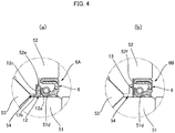
- FIGS. 4(a) and 4(b) are partially enlarged cross-sectional views illustrating two examples of oil seal structure to seal the first gap part 54 of the crossed roller bearing 5. These oil seal structures can be used instead of the above oil seal 6.
- An oil seal structure 6A illustrated in FIG. 4(a) has an oil seal 6 and a partition plate 12 in the first gap part 54, the partition plate being located adjacent to the oil seal 6 at the side of rollers 53.
- the partition plate 12 which is made from resin material and is formed to have an L-shaped cross-sectional shape, is provided with an annular part 12a and a press-fitting cylindrical part 12b integrally formed on the inner-peripheral edge of the annular part 12a.
- the press-fitting cylindrical body 12b is press-fitted and fixed to the outer peripheral surface 51d of the inner race 51.
- the outer race 52 is formed at an inner peripheral surface thereof with an inner peripheral surface part 52e having a stepped profile, the inner peripheral surface part corresponding to an outer peripheral surface part 12c having a stepped profile of the partition plate 12.
- These outer peripheral surface part 12c and inner peripheral surface part 52e face to each other across a very small gap so as to form a labyrinth seal. Lubricant is reliably prevented from leaking outside by means of the partition plate 12 and the oil seal 6.
- An oil seal structure 6B illustrated in FIG. 4(b) has an oil seal 6 and an annular sheet 13 in a first gap part 54, the sheet being located adjacent to the oil seal 6 at the side of rollers 53 and being made from non-woven fabrics or other porous materials.
- Himeron (product name) sheet can be used.
- the sheet 13 is sandwiched between an annular stepped surface 52f formed on the inner-peripheral surface part of the outer race 52 and the oil seal 6 press-fitted and fixed to the inner peripheral surface of the outer race.
- Lubricant is reliably prevented from leaking to the outside by means of the sheet 13 and the oil seal 6.
- foreign matters entering from outside through the oil seal 6 are captured by the sheet 13, whereby reliably preventing foreign matters from entering the raceway groove.
- the above-mentioned embodiment employs the crossed roller bearing 5 to support the internal gear and the external gear in a relatively rotatable state.
- Another bearing such as double-row ball bearing can be employed instead of the crossed roller bearing 5.
Landscapes
- Engineering & Computer Science (AREA)
- General Engineering & Computer Science (AREA)
- Mechanical Engineering (AREA)
- Chemical & Material Sciences (AREA)
- Oil, Petroleum & Natural Gas (AREA)
- Rolling Contact Bearings (AREA)
- Sealing Of Bearings (AREA)
- General Details Of Gearings (AREA)
- Retarders (AREA)
- Sealing With Elastic Sealing Lips (AREA)
- Diaphragms And Bellows (AREA)
Abstract
Description
- The present invention relates to a silk hat-type strain wave gear device. In particular, the present invention pertains to a silk hat-type strain wave gear device provided with a crossed roller bearing or other bearing to support an internal gear and an external gear in a relatively rotatable state.
- A silk hat-type strain wave gear device has an internal gear and an external gear, between which a bearing such as a crossed roller bearing, for example, is arranged to support the internal and external gears in a state in which they are relatively rotatable with each other. The crossed roller bearing is formed with gap parts on both sides of rollers between inner and outer races thereof. One of the gap parts, which is an outer gap part opening to the outside, is sealed by an oil seal to prevent lubricant from leaking to the outside. Silk hat-type strain wave gear devices of this configuration are disclosed in
Patent documents - Gap is provided on the outer peripheral side of an external gear so that the external gear, which is flexed in a radial direction, does not interfere with components arranged on the outer peripheral side of the external gear. In
Patent document 1, there is formed an annular gap along the cylindrical body and diaphragm of an external gear between the external gear and the inner race of a crossed roller bearing surrounding the outer periphery of the external gear. InPatent document 2, an annular gap is formed between an external gear and the inner peripheral-side portion of an internal gear. The internal gear is fixed to the inner race of a crossed roller bearing that surrounds the outer periphery of the external gear. -
- Patent document 1:
JP 2000-186718 A - Patent document 2:
JP 2007-16838 A - The gap formed along the outer peripheral surface of the external gear extends from a meshing section between the external and internal gears to the inner end face of the crossed roller bearing. A gap between the inner and outer races opens on the inner end face of the crossed roller bearing. This gap is therefore communicated with the gap formed along the outer peripheral surface of the external gear.
- During operation of the strain wave gear device, the external gear is repeatedly flexed in the radial direction while the external gear or the internal gear is rotated. Accompanied by this operation, lubricant which is being supplied to the meshing section is pushed out to the outer peripheral side of the external gear through the gap formed along the outer peripheral surface of the external gear, and flows into the crossed roller bearing through the gap thereof. The lubricant flowed into the crossed roller bearing remains therein because the opposite-side gap of the crossed roller bearing is sealed by an oil seal. However, if excessive amount of lubricant flows into the crossed roller bearing, there is a possibility that lubricant be leaked to the outside from the oil seal.
- An object of the present invention is to provide a silk hat-type strain wave gear device which can prevent or limit lubricant from leaking to the outside from the bearing.
- In order to solve the above problems, a silk hat-type strain wave gear device of the present invention has:
- a rigid internal gear;
- an external gear having a silk hat shape, the external gear being provided with a flexible cylindrical body coaxially arranged inside the internal gear, external teeth formed on the cylindrical body, a diaphragm extending outward in a radial direction from an end of the cylindrical body, and an annular rigid boss formed continuously on an outer peripheral edge of the diaphragm;
- a wave generator for flexing the cylindrical body of the external gear into a non-circular shape to mesh the external teeth with internal teeth of the internal gear and for moving a meshing position of the external teeth with the internal teeth in a circumferential direction;
- a bearing for supporting the internal gear and the external gear in a relatively rotatable state;
- a gear-side gap part having an annular cross-section, the gear-side gap part extending along the diaphragm and the cylindrical body from the outer peripheral edge of the diaphragm of the external gear to a meshing section between the external teeth and the internal teeth;
- a first gap part having an annular cross-section and a second gap part having an annular cross-section, the first gap part being formed between inner and outer races of the bearing and being opened in one first end face of the bearing, the second gap part being formed between the inner and outer races of the bearing and being opened in the other second end face of the bearing;
- an oil seal for sealing the first gap part; and a bearing seal for separating the second gap part from the gear-side gap part,
- wherein the bearing seal seals an opening end of the second gap part communicating with the gear-side gap part from a side of the gear-side gap part, in a manner that the bearing seal prevents lubricant from flowing into the second gap part from the gear-side gap part and allows lubricant to flow out to the gear-side gap part from the second gap part.
- The bearing seal blocks between the gear-side gap part and the second gap part of the bearing, which prevents or limits excessive amount of lubricant form flowing into the bearing. In addition, excess lubricant that has flowed into the bearing can flow back to the gear-side gap part through the bearing seal. Thus, the excess lubricant flowed into the bearing is prevented or limited from leaking through the oil seal to the outside.
- In addition, different from a case in which a typical oil seal is used to seal the second gap part, the bearing seal allows lubricant to flow out to the gear-side gap part from the second gap part of the bearing. Excessive lubricant that has supplied to the bearing can be returned to the gear-side gap part through the bearing seal before leaking out from the oil seal side.
- In the silk hat-type strain wave gear device of the present invention, the inner race of the bearing can be arranged between the diaphragm and the internal gear in a direction of a center axis line and be directly fixed to the internal gear. While, the outer race can be directly fixed to the rigid boss. In this case, the gear-side gap part includes, from the side of the meshing section, an axial-direction gap section formed between the cylindrical body and the inner peripheral surface of the inner race and a radial-direction gap section formed between the diaphragm and the an end face of the inner race. The opening end of the second gap part is positioned at an outer-peripheral-side portion of the radial-direction gap section. In this case, the bearing seal can be formed to have an annular outer-peripheral-side seal part for sealing a joint surface between the outer race and the rigid boss and an annular inner-peripheral-side seal part that extends from the outer-peripheral-side seal part into the radial-direction gap part and seals an opening end of the second gap part.
- The outer-peripheral-side seal part of the bearing seal seals the joint surface between the outer race and the rigid boss. Thus, O-ring or another seal member become unnecessary for sealing the joint surface between the outer race and the rigid boss.
- Here, it is possible that an annular bearing-seal plate be attached to an inner-race end face where the opening end of the inner race is located so that it covers the inner-race end face, and that the inner-peripheral-side seal section of the bearing seal be pressed against the bearing-seal plate in a slidable state.
- Because the bearing seal is fixed to the side of the outer race, the inner-peripheral-side seal section thereof relatively slides along the inner-race end face. There is a case in which steps, cuts or the like are formed on the inner-race end face. The inner-peripheral-side seal section that slides on the inner-race end face can be damaged by steps, cuts or the like, and the sealing property thereof can be deteriorated. These defects can be avoided by providing the bearing-seal plate and making the inner-peripheral-side seal section to slide along the flat surface thereof.
- For example, in such a type of bearing is used in which rolling elements are inserted between outer and inner races from an insertion hole formed in the inner race, the inner-race end face is formed with steps or cuts between an insertion hole and a plug that seals the insertion hole. In this case, the bearing-seal plate is attached to the inner-race end face to cover the insertion hole and the plug.
- Next, in order to reliably prevent lubricant from leaking out to the outside through the oil seal from the bearing, an annular partition plate can be arranged in the first gap part, the partition plate being located adjacent to the oil seal at the side of the rolling elements. The partition plate is, for example, press fitted to the outer peripheral surface of the inner race. In addition, a labyrinth seal is formed between the partition plate and the inner peripheral surface part of the outer race facing the partition plate.
- It is possible that the first gap part be provided with an annular sheet made from non-woven fabrics or other porous material at a position adjacent to the oil seal at the side of the rolling elements. The sheet can be sandwiched between the outer race and the oil seal, for example.
-
-
FIG. 1(a) is a schematic longitudinal cross-sectional view illustrating an embodiment of a silk hat-type strain wave gear device according to the present invention andFIG. 1(b) is a schematic end view thereof; -
FIG. 2 is a partial cross-sectional view of a silk hat-type strain wave gear device; -
FIG. 3 is a partial cross-sectional view illustrating a case in which a crossed roller bearing of the outer-race divided type is employed; and -
FIGS. 4(a) and 4(b) are explanatory views illustrating an - example of an oil-seal structure of the bearing.
- An embodiment of a silk hat-type strain wave gear device according to the present invention will be described with reference to the drawings. The embodiment described below is an example of the present invention but is not intended to limit the present invention to the structure thereof.
-
FIG. 1(a) is a schematic longitudinal cross-sectional view illustrating a silk hat-type strain wave gear device when cut along line a-a, andFIG. 1(b) is a schematic end view thereof when cut along line b-b.FIG. 2 is a partial cross-sectional view of a silk hat-type strain wave gear device. A silk hat-type strain wave gear device 1 (hereinafter simply refer to as "a strainwave gear device 1") is provided with a rigidinternal gear 2, a flexibleexternal gear 3 coaxially arranged inside theinternal gear 2, awave generator 4 arranged inside theexternal gear 3, and a crossed roller bearing 5 (hereinafter simply refer to as "abearing 5") for supporting theinternal gear 2 and theexternal gear 3 in a relatively rotatable state. - The
internal gear 2 has anannular member 21 of an approximately rectangular cross-section, a circular inner peripheral surface of which is formed withinternal teeth 22. Theexternal gear 3 has a silk hat shape and is provided with acylindrical body 31 that is flexible in the radial direction,external teeth 32 formed on the outer peripheral surface part at the side of the front-end opening of thecylindrical body 31, adiscoid diaphragm 33 extending outward in the radial direction from the rear end part of thecylindrical body 31, and an annularrigid boss 34 that has a rectangular cross-section and is formed continuously on the outer peripheral edge of thediaphragm 33. Thewave generator 4 causes thecylindrical body 31 of theexternal gear 3 to flex into a non-circular shape, for example, an elliptical shape and meshexternal teeth 32 withinternal teeth 22, and causes meshing positions of theexternal teeth 32 with theinternal teeth 22 to rotate in the circumferential direction. - The
bearing 5 is arranged in a state coaxially surrounding thecylindrical body 31 of theexternal gear 3. Thebearing 5 has aninner race 51 that is positioned between thediaphragm 33 of theexternal gear 3 and theinternal gear 2 when viewed along a direction of acenter axis line 1a, and that is coaxially fixed to an annular end face 23 of theinternal gear 2. Thebearing 5 has anouter race 52 that is arranged adjacent to therigid boss 34 and is coaxially fixed to anannular end face 34a of therigid boss 34.Rollers 53 are inserted into a raceway groove having a rectangular cross-section formed between theinner race 51 and theouter race 52 of thebearing 5. Afirst gap part 54 and asecond gap part 55 are formed on both sides of the raceway groove. Thefirst gap part 54 located at the side of theinternal gear 2 is opened to the outside from one end face of thebearing 5, while thesecond gap part 55 is opened on the other end face of thebearing 5. Thefirst gap part 54 opening to the outside is sealed by anoil seal 6. - The strain
wave gear device 1 is provided with a gear-side gap part 8 having an annular cross section, the gear-side gap part extending from ameshing section 7 of theinternal teeth 22 and theexternal teeth 32 along thecylindrical body 31 and thediaphragm 33 of theexternal gear 3. The gear-side gap part 8 is provided with, from themeshing section 7, an axial-direction gap section 8a formed between thecylindrical body 31 and the inner peripheral surface of theinner race 51 and a radial-direction gap section 8b formed between thediaphragm 33 and theinner race 51. Thesecond gap part 55 of the bearing side has anopening end 55a that is positioned in a portion of an outer-peripheral-end side of the radial-direction gap part 8b. - The radial-
direction gap part 8b is separated from thesecond gap part 55 of the bearing side by anannular bearing seal 9. In this embodiment, an openingend 55a of thesecond gap part 55 is sealed by theannular bearing seal 9 from the side of the radial-direction gap part 8b. Thebearing seal 9 can prevent inflow of lubricant from the gear-side gap part 8 to thesecond gap part 55, and at the same time allows lubricant to flow out to the gear-side gap part 8 from thesecond gap part 55. - The
bearing 5 is such a type of bearing in which therollers 52 are inserted into the raceway groove between theinner race 51 and theouter race 52 from theinsertion hole 56 formed in theinner race 51. Theinsertion hole 56 opens across the inner-race end face 51b and the inner-race innerperipheral surface 51c. Theinsertion hole 56 is sealed by aplug 57 attached thereto. A bearing-seal plate 10 of having an L-shaped cross-section is attached in a state in which it covers the inner-race end face 51b and a part of the inner-race innerperipheral surface 51c. The bearing-seal plate 10 covers and hides theinsertion hole 56 and theplug 57, and also steps, cuts and the like formed between the insertion hole and the plug. The bearing-seal plate 10 is a metal plate, for example. - The
bearing seal 9 is provided with: an annular outer-peripheral-side seal part 9a that seals the joint surfaces (52a and 34a) between theouter race 52 and therigid boss 34; and an annular inner-peripheral-side seal part 9b that extends from the outer-peripheral-side seal part 9a into the radial-direction gap part 8b and seals the openingend 55a of thesecond gap part 55. - The outer-peripheral-
side seal part 9a is constituted by a metal ring and a synthetic rubber such as a nitrile rubber and is formed to have an approximately rectangular cross-section. Theouter race 52 has anend face 52a that is in contact with theannular end face 34a of therigid boss 34 and is formed at an inner-peripheral edge part thereof with a cutout having a rectangular cross section. The outer-peripheral seal part 9a is accommodated in the cutout. The inner-peripheral-side seal part 9b (a seal lip part) extends in an inclined direction toward the inner-race side from the inner-peripheral edge of the outer-peripheral-side seal part 9a, the inner-peripheral-side seal part 9b being made from synthetic rubber and is smaller in width than the outer-peripheral-side seal part. Thetip end 9c (a lip tip end) of the inner-peripheral-side seal part 9b is pressed against the bearing-seal plate 10 in a slidable state. agap 8c is formed between thebearing seal 9 and thediaphragm 33. With thegap 8c, thediaphragm 33 of theexternal gear 3 flexed by thewave generator 4 is prevented from interfering with thebearing seal 9. - The strain
wave gear device 1 of the present embodiment is provided with thebearing seal 9 that functions as a check valve. It is possible to prevent lubricant for lubricating themeshing section 7 and other sections from flowing into thesecond gap part 55 in thebearing 5 from the gear-side gap part 8. Thus, excessive amount of lubricant can be prevented or limited from flowing into the bearing 5 (thesecond gap part 55, the raceway groove, the first gap part 54). In addition, even when excessive lubricant flows into thebearing 5, it returns to the gear-side gap part 8 through thebearing seal 9 without leaking outside from theouter oil seal 6. Therefore, lubricant can be prevented or limited from leaking outside from theoil seal 6 of thebearing 5. - The above-mentioned crossed
roller bearing 5 is a bearing in which therollers 53 are inserted from theinsertion hole 56 formed in theinner race 51. A crossed roller bearing of an outer-race divided type can also be employed. -
FIG. 3 is a partial cross-sectional view illustrating a silk hat-type strain wave gear device in which a crossed roller bearing of an outer-race divided type is employed. Since a silk hat-type strainwave gear device 1A has the basic structure that is the same as that of the above-mentioned strainwave gear device 1, the corresponding portions are denoted by the same reference numerals and their explanations are omitted. A crossedroller bearing 5A of this embodiment is provided with aninner race 58, anouter race 59 constituted by two outer-race pieces rollers 60 inserted between the inner and outer races. Abearing seal 9 has an inner-peripheral-side seal part 9b, atip end 9c of which extends to an inner-race end face 58a of theinner race 58 beyond an openingend 55a of asecond gap part 55. In addition, an inner-peripheral-side seal part 9b has atip end 9c that is pressed against the inner-race end face 58a of theinner race 58 in a slidable state to seal the openingend 55a. -
FIGS. 4(a) and 4(b) are partially enlarged cross-sectional views illustrating two examples of oil seal structure to seal thefirst gap part 54 of the crossedroller bearing 5. These oil seal structures can be used instead of theabove oil seal 6. - An
oil seal structure 6A illustrated inFIG. 4(a) has anoil seal 6 and apartition plate 12 in thefirst gap part 54, the partition plate being located adjacent to theoil seal 6 at the side ofrollers 53. Thepartition plate 12, which is made from resin material and is formed to have an L-shaped cross-sectional shape, is provided with anannular part 12a and a press-fittingcylindrical part 12b integrally formed on the inner-peripheral edge of theannular part 12a. The press-fittingcylindrical body 12b is press-fitted and fixed to the outerperipheral surface 51d of theinner race 51. - The
outer race 52 is formed at an inner peripheral surface thereof with an innerperipheral surface part 52e having a stepped profile, the inner peripheral surface part corresponding to an outerperipheral surface part 12c having a stepped profile of thepartition plate 12. These outerperipheral surface part 12c and innerperipheral surface part 52e face to each other across a very small gap so as to form a labyrinth seal. Lubricant is reliably prevented from leaking outside by means of thepartition plate 12 and theoil seal 6. - An
oil seal structure 6B illustrated inFIG. 4(b) has anoil seal 6 and anannular sheet 13 in afirst gap part 54, the sheet being located adjacent to theoil seal 6 at the side ofrollers 53 and being made from non-woven fabrics or other porous materials. For example, Himeron (product name) sheet can be used. - The
sheet 13 is sandwiched between an annular steppedsurface 52f formed on the inner-peripheral surface part of theouter race 52 and theoil seal 6 press-fitted and fixed to the inner peripheral surface of the outer race. Lubricant is reliably prevented from leaking to the outside by means of thesheet 13 and theoil seal 6. In addition, foreign matters entering from outside through theoil seal 6 are captured by thesheet 13, whereby reliably preventing foreign matters from entering the raceway groove. - The above-mentioned embodiment employs the crossed
roller bearing 5 to support the internal gear and the external gear in a relatively rotatable state. Another bearing such as double-row ball bearing can be employed instead of the crossedroller bearing 5.
Claims (7)
- A silk hat-type strain wave gear device comprising:a rigid internal gear;an external gear having a silk hat shape, the external gear being provided with a flexible cylindrical body coaxially arranged inside the internal gear, external teeth formed on the cylindrical body, a diaphragm extending outward in a radial direction from an end of the cylindrical body, and an annular rigid boss formed continuously on an outer peripheral edge of the diaphragm;a wave generator for flexing the cylindrical body of the external gear into a non-circular shape to mesh the external teeth with internal teeth of the internal gear and for moving a meshing position of the external teeth with the internal teeth in a circumferential direction;a bearing for supporting the internal gear and the external gear in a relatively rotatable state;a gear-side gap part having an annular cross-section, the gear-side gap part extending along the diaphragm and the cylindrical body from the outer peripheral edge of the diaphragm of the external gear to a meshing section between the external teeth and the internal teeth;a first gap part and a second gap part, the first gap part being formed between inner and outer races of the bearing and being opened in one first end face of the bearing, the second gap part being formed between the inner and outer races of the bearing and being opened in the other second end face of the bearing;an oil seal for sealing the first gap part; anda bearing seal for separating the second gap part from the gear-side gap part,wherein the bearing seal seals an opening end of the second gap part communicating with the gear-side gap part from a side of the gear-side gap part, in a manner that the bearing seal prevents lubricant from flowing into the second gap part from the gear-side gap part and allows lubricant to flow out to the gear-side gap part from the second gap part.
- The silk hat-type strain wave gear device according to claim 1,
wherein the inner race of the bearing is located between the diaphragm and the internal gear in a direction of a center axis line and is coaxially fixed to the internal gear;
the outer race of the bearing is coaxially fixed to the rigid boss;
the gear-side gap part comprises, from the meshing section, an axial-direction gap section formed between the cylindrical body and the inner peripheral surface of the inner race and a radial-direction gap section formed between the diaphragm and an end face of the inner race;
the opening end of the second gap part is positioned at an outer peripheral side portion of the radial-direction gap section; and
wherein the bearing seal comprises:an annular outer-peripheral-side seal part for sealing a joint surface between the outer race and the rigid boss; andan annular inner-peripheral-side seal part that extends from the outer-peripheral-side seal part into the radial-direction gap part and seals an opening end of the second gap part. - The silk hat-type strain wave gear device according to claim 2, further comprising:an annular bearing-seal plate that is attached to an inner-race end face of the inner race in a state covering the inner-race end face where the opening end of the second gap part is located, andwherein the inner-peripheral-side seal section of the bearing seal is pressed against the bearing-seal plate in a slidable state.
- The silk hat-type strain wave gear device according to claim 3,
wherein the inner race of the bearing has an insertion hole for inserting rolling elements between the inner race and the outer race and a plug for sealing the insertion hole;
the insertion hole opens in the inner-race end face; and
the insertion hole and the plug are covered and hidden by the bearing-seal plate. - The silk hat-type strain wave gear device according to claim 1, further comprising:an annular partition plate arranged in the first gap part and located adjacent to the oil seal at a side of rolling elements of the bearing;wherein the partition plate is fixed to the inner race, anda labyrinth seal is formed between the partition plate and the inner peripheral surface part of the outer race facing the partition plate.
- The silk hat-type strain wave gear device according to claim 1, further comprising:
an annular sheet made from a porous material, the annular sheet being arranged in the first gap part and located adjacent to the oil seal at the side of rolling elements of the bearing. - The silk hat-type strain wave gear device according to claim 1, further comprising:an annular bearing-seal plate that is attached to an inner-race end face of the inner race in a state covering the inner-race end face where the opening end of the second gap part is located;wherein the bearing is a crossed roller bearing;the inner race of the crossed roller bearing has an insertion hole for inserting rolling elements between the inner race and the outer race and a plug for sealing the insertion hole;the insertion hole opens in the inner-race end face;the bearing-seal plate is attached to the inner-race end face to cover and hide the insertion hole and the plug;the inner race is located between the diaphragm and the internal gear in an axial direction and is coaxially fixed to the internal gear;the outer race is coaxially fixed to the rigid boss;the gear-side gap part comprises an axial-direction gap section formed between the cylindrical body and the inner peripheral surface of the inner race and a radial-direction gap section formed between the diaphragm and an end face of the inner race when viewed from the meshing part;the opening end of the second gap part is positioned at an outer peripheral side portion of the radial-direction gap section; andwherein the bearing seal comprises:an annular outer-peripheral-side seal part for sealing a joint surface between the outer race and the rigid boss; andan annular inner-peripheral-side seal part that extends from the outer-peripheral-side seal part into the radial-direction gap part and seals an opening end of the second gap part,the inner-peripheral-side seal part of the bearing seal being pressed against the bearing-seal plate in a slidable state.
Applications Claiming Priority (1)
| Application Number | Priority Date | Filing Date | Title |
|---|---|---|---|
| PCT/JP2017/014727 WO2018189798A1 (en) | 2017-04-10 | 2017-04-10 | Silk hat-type strain wave gear device |
Publications (3)
| Publication Number | Publication Date |
|---|---|
| EP3611399A1 true EP3611399A1 (en) | 2020-02-19 |
| EP3611399A4 EP3611399A4 (en) | 2020-09-23 |
| EP3611399B1 EP3611399B1 (en) | 2021-08-11 |
Family
ID=63792457
Family Applications (1)
| Application Number | Title | Priority Date | Filing Date |
|---|---|---|---|
| EP17905051.3A Active EP3611399B1 (en) | 2017-04-10 | 2017-04-10 | Silk hat-type strain wave gear device |
Country Status (7)
| Country | Link |
|---|---|
| US (1) | US10823278B2 (en) |
| EP (1) | EP3611399B1 (en) |
| JP (1) | JP6695646B2 (en) |
| KR (1) | KR102175892B1 (en) |
| CN (1) | CN110462258B (en) |
| TW (1) | TWI750320B (en) |
| WO (1) | WO2018189798A1 (en) |
Cited By (1)
| Publication number | Priority date | Publication date | Assignee | Title |
|---|---|---|---|---|
| DE102024118992A1 (en) * | 2024-07-04 | 2026-01-08 | Schaeffler Technologies AG & Co. KG | Wave gear with a labyrinth seal |
Families Citing this family (16)
| Publication number | Priority date | Publication date | Assignee | Title |
|---|---|---|---|---|
| JP2018168956A (en) * | 2017-03-30 | 2018-11-01 | セイコーエプソン株式会社 | Robot and gear unit |
| JP7323890B2 (en) * | 2019-06-20 | 2023-08-09 | 内山工業株式会社 | Sealed structure |
| DE102020109646B4 (en) * | 2020-04-07 | 2024-09-12 | Harmonic Drive Se | Pivot bearing and gearbox |
| CN115335619B (en) * | 2020-04-10 | 2025-02-28 | 谐波传动系统有限公司 | Lubricant seal structure, wave gear device, and actuator |
| DE102020206602A1 (en) | 2020-05-27 | 2021-12-02 | Zf Friedrichshafen Ag | NILOS ring with bead |
| WO2021245920A1 (en) * | 2020-06-05 | 2021-12-09 | 株式会社ハーモニック・ドライブ・システムズ | Lubricant sealing structure, wave-motion gear device and actuator |
| JP7533005B2 (en) * | 2020-08-14 | 2024-08-14 | セイコーエプソン株式会社 | Gearing and robots |
| JP7419193B2 (en) * | 2020-08-27 | 2024-01-22 | 住友重機械工業株式会社 | Flexible mesh gear system |
| DE102022100356B3 (en) | 2022-01-10 | 2023-01-19 | Schaeffler Technologies AG & Co. KG | harmonic drive |
| CN115111341B (en) * | 2022-07-11 | 2024-04-12 | 深圳市大族机器人有限公司 | reducer |
| WO2024047743A1 (en) * | 2022-08-30 | 2024-03-07 | ヤマハ発動機株式会社 | Gearing device and robot |
| JP2024064438A (en) * | 2022-10-28 | 2024-05-14 | 住友重機械工業株式会社 | Gearing |
| CN116816810A (en) * | 2023-06-27 | 2023-09-29 | 中国铁建重工集团股份有限公司 | Bearing with rolling bodies capable of being quickly assembled and disassembled |
| JP7610663B1 (en) | 2023-09-06 | 2025-01-08 | 上銀科技股▲分▼有限公司 | Harmonic reducer to prevent oil spills |
| US12276326B1 (en) * | 2023-11-08 | 2025-04-15 | Tung Pei Industrial Co., Ltd. | Wave generator with sealing plate and installation method thereof |
| DE102024121361B4 (en) * | 2024-07-26 | 2026-02-05 | Schaeffler Technologies AG & Co. KG | Wave gear |
Family Cites Families (31)
| Publication number | Priority date | Publication date | Assignee | Title |
|---|---|---|---|---|
| JPS6170631U (en) | 1984-10-16 | 1986-05-14 | ||
| JP2569649Y2 (en) | 1992-07-20 | 1998-04-28 | 株式会社ミクニ | Fuel injection device |
| JPH0989053A (en) * | 1995-09-29 | 1997-03-31 | Harmonic Drive Syst Ind Co Ltd | Wave gearing |
| JP3781313B2 (en) * | 1996-03-18 | 2006-05-31 | 株式会社ハーモニック・ドライブ・システムズ | Top hat flexure meshing gear system |
| JP3781312B2 (en) * | 1996-03-18 | 2006-05-31 | 株式会社ハーモニック・ドライブ・システムズ | Lubrication mechanism of flexure mesh gear system |
| JP3835709B2 (en) * | 1996-03-18 | 2006-10-18 | 株式会社ハーモニック・ドライブ・システムズ | Lubrication mechanism of flexibly meshing gear system |
| JP3788527B2 (en) * | 1996-05-17 | 2006-06-21 | 株式会社ハーモニック・ドライブ・システムズ | Method for forming coating on teeth of flexible meshing gear device |
| JPH09303497A (en) * | 1996-05-21 | 1997-11-25 | Harmonic Drive Syst Ind Co Ltd | Top hat type flexible meshing gear unit |
| US5984048A (en) * | 1997-09-10 | 1999-11-16 | Harmonic Drive Systems, Inc. | Lubricant supplying mechanism for a wave gear drive |
| JP4169411B2 (en) | 1998-12-17 | 2008-10-22 | 株式会社ハーモニック・ドライブ・システムズ | Cross roller bearing |
| JP4187331B2 (en) | 1998-12-22 | 2008-11-26 | 株式会社ハーモニック・ドライブ・システムズ | Cross roller bearing |
| JP4390124B2 (en) * | 2001-05-22 | 2009-12-24 | 株式会社ハーモニック・ドライブ・システムズ | Lightweight bearing manufacturing method |
| JP2004190706A (en) | 2002-12-09 | 2004-07-08 | Ntn Corp | Rolling bearing lubricating structure |
| US6997618B2 (en) | 2003-12-29 | 2006-02-14 | United Technologies Corporation | Bearing housing with divided drainage and oil pooling annulus |
| JP2007016838A (en) * | 2005-07-06 | 2007-01-25 | Nabtesco Corp | Top hat wave gear device |
| KR20070016838A (en) | 2005-08-05 | 2007-02-08 | 주식회사 대우일렉트로닉스 | Main Chassis for Electronics |
| DE102007016729A1 (en) * | 2007-04-07 | 2008-10-09 | Zf Lenksysteme Gmbh | Radial flexible rolling bearing |
| CN102434635A (en) * | 2011-12-19 | 2012-05-02 | 福建长江工业有限公司 | Integrated harmonic drive motor |
| JP2013238278A (en) * | 2012-05-15 | 2013-11-28 | Honda Motor Co Ltd | Harmonic drive gearing |
| CN103527720A (en) * | 2012-07-05 | 2014-01-22 | 北京精密机电控制设备研究所 | Harmonic reducer |
| DE112012000394T5 (en) * | 2012-12-12 | 2014-08-28 | Harmonic Drive Systems Inc. | Corrugated gear unit with input bearings |
| CN104379966B (en) * | 2013-06-20 | 2017-03-08 | 谐波传动系统有限公司 | Wave gear device |
| KR101622914B1 (en) * | 2013-06-20 | 2016-05-20 | 가부시키가이샤 하모닉 드라이브 시스템즈 | Hollow-type strain wave gearing unit |
| US10006534B2 (en) * | 2013-06-20 | 2018-06-26 | Harmonic Drive Systems Inc. | Bearing holder, bearing mechanism, and strain wave gearing device |
| US9441721B2 (en) | 2013-09-12 | 2016-09-13 | Harmonic Drive Systems Inc. | Strain wave gearing unit |
| WO2015040739A1 (en) * | 2013-09-20 | 2015-03-26 | 株式会社ハーモニック・ドライブ・システムズ | Oil seal structure and strain wave gear device |
| JP6052835B2 (en) * | 2014-05-16 | 2016-12-27 | 株式会社ハーモニック・ドライブ・システムズ | Hollow wave gear device and hollow actuator |
| CN107110302B (en) * | 2015-01-13 | 2019-06-14 | 谐波传动系统有限公司 | Wave gear unit |
| DE102015104308A1 (en) * | 2015-03-23 | 2016-09-29 | Harmonic Drive Ag | Gearbox kit with an output bearing and a voltage wave gearbox which can be stored in it |
| KR102065013B1 (en) * | 2015-11-17 | 2020-01-10 | 가부시키가이샤 하모닉 드라이브 시스템즈 | Strain-wave gear device |
| WO2018157910A1 (en) * | 2017-02-28 | 2018-09-07 | Harmonic Drive Ag | Strain wave gear mechanism with an inner seal |
-
2017
- 2017-04-10 KR KR1020197027427A patent/KR102175892B1/en active Active
- 2017-04-10 EP EP17905051.3A patent/EP3611399B1/en active Active
- 2017-04-10 WO PCT/JP2017/014727 patent/WO2018189798A1/en not_active Ceased
- 2017-04-10 JP JP2019512075A patent/JP6695646B2/en active Active
- 2017-04-10 US US16/493,111 patent/US10823278B2/en active Active
- 2017-04-10 CN CN201780088780.1A patent/CN110462258B/en active Active
-
2018
- 2018-02-12 TW TW107104961A patent/TWI750320B/en active
Cited By (1)
| Publication number | Priority date | Publication date | Assignee | Title |
|---|---|---|---|---|
| DE102024118992A1 (en) * | 2024-07-04 | 2026-01-08 | Schaeffler Technologies AG & Co. KG | Wave gear with a labyrinth seal |
Also Published As
| Publication number | Publication date |
|---|---|
| TW201837341A (en) | 2018-10-16 |
| CN110462258A (en) | 2019-11-15 |
| KR102175892B1 (en) | 2020-11-06 |
| EP3611399B1 (en) | 2021-08-11 |
| JPWO2018189798A1 (en) | 2019-12-19 |
| CN110462258B (en) | 2022-08-23 |
| US10823278B2 (en) | 2020-11-03 |
| EP3611399A4 (en) | 2020-09-23 |
| WO2018189798A1 (en) | 2018-10-18 |
| KR20190120286A (en) | 2019-10-23 |
| JP6695646B2 (en) | 2020-05-20 |
| US20200072338A1 (en) | 2020-03-05 |
| TWI750320B (en) | 2021-12-21 |
Similar Documents
| Publication | Publication Date | Title |
|---|---|---|
| EP3611399B1 (en) | Silk hat-type strain wave gear device | |
| US9751576B2 (en) | Sealing devices for anti-friction bearing | |
| EP1808580A3 (en) | Squeeze film damper using low pressure oil | |
| EP3379103B1 (en) | Strain-wave gear device | |
| WO2020100309A1 (en) | Unit-type strain wave gearing device | |
| JP2017129174A (en) | Roller bearing | |
| JP2011127702A (en) | Rolling bearing | |
| JP2006207613A (en) | Sealing device for rolling bearing and sealed rolling bearing | |
| JP2016166625A (en) | Rolling bearing with filter | |
| JP6164108B2 (en) | Sealing device | |
| JPWO2008087926A1 (en) | Tapered roller bearings | |
| JP6248674B2 (en) | Thrust roller bearing | |
| JP5661410B2 (en) | Ball bearing cage and ball bearing | |
| WO2011074468A1 (en) | Rolling bearing | |
| JP2004060677A (en) | Rolling bearing | |
| JP2012057754A (en) | Cage for rolling bearing and rolling bearing using the same | |
| US8202006B2 (en) | Sealing device, rolling bearing, and rolling bearing for wheel | |
| JP2009047255A (en) | Clutch-release bearing | |
| JP2007192258A (en) | Rolling bearing with seal | |
| JP2000230562A (en) | Rolling bearing | |
| JP6515447B2 (en) | Idler pulley bearings | |
| US10385920B1 (en) | Combination bearing with oil retainer feature | |
| JP2009180244A (en) | Clutch release bearing and clutch release bearing device with the same | |
| JP2016089882A (en) | Rolling bearing | |
| JP2015200332A (en) | rolling bearing with filter |
Legal Events
| Date | Code | Title | Description |
|---|---|---|---|
| STAA | Information on the status of an ep patent application or granted ep patent |
Free format text: STATUS: THE INTERNATIONAL PUBLICATION HAS BEEN MADE |
|
| PUAI | Public reference made under article 153(3) epc to a published international application that has entered the european phase |
Free format text: ORIGINAL CODE: 0009012 |
|
| STAA | Information on the status of an ep patent application or granted ep patent |
Free format text: STATUS: REQUEST FOR EXAMINATION WAS MADE |
|
| 17P | Request for examination filed |
Effective date: 20190926 |
|
| AK | Designated contracting states |
Kind code of ref document: A1 Designated state(s): AL AT BE BG CH CY CZ DE DK EE ES FI FR GB GR HR HU IE IS IT LI LT LU LV MC MK MT NL NO PL PT RO RS SE SI SK SM TR |
|
| AX | Request for extension of the european patent |
Extension state: BA ME |
|
| DAV | Request for validation of the european patent (deleted) | ||
| DAX | Request for extension of the european patent (deleted) | ||
| REG | Reference to a national code |
Ref country code: DE Ref legal event code: R079 Ref document number: 602017044079 Country of ref document: DE Free format text: PREVIOUS MAIN CLASS: F16H0001320000 Ipc: F16H0049000000 |
|
| A4 | Supplementary search report drawn up and despatched |
Effective date: 20200824 |
|
| RIC1 | Information provided on ipc code assigned before grant |
Ipc: F16H 49/00 20060101AFI20200818BHEP |
|
| GRAP | Despatch of communication of intention to grant a patent |
Free format text: ORIGINAL CODE: EPIDOSNIGR1 |
|
| STAA | Information on the status of an ep patent application or granted ep patent |
Free format text: STATUS: GRANT OF PATENT IS INTENDED |
|
| INTG | Intention to grant announced |
Effective date: 20210303 |
|
| GRAS | Grant fee paid |
Free format text: ORIGINAL CODE: EPIDOSNIGR3 |
|
| GRAA | (expected) grant |
Free format text: ORIGINAL CODE: 0009210 |
|
| STAA | Information on the status of an ep patent application or granted ep patent |
Free format text: STATUS: THE PATENT HAS BEEN GRANTED |
|
| AK | Designated contracting states |
Kind code of ref document: B1 Designated state(s): AL AT BE BG CH CY CZ DE DK EE ES FI FR GB GR HR HU IE IS IT LI LT LU LV MC MK MT NL NO PL PT RO RS SE SI SK SM TR |
|
| REG | Reference to a national code |
Ref country code: CH Ref legal event code: EP |
|
| REG | Reference to a national code |
Ref country code: DE Ref legal event code: R096 Ref document number: 602017044079 Country of ref document: DE |
|
| REG | Reference to a national code |
Ref country code: IE Ref legal event code: FG4D Ref country code: AT Ref legal event code: REF Ref document number: 1419698 Country of ref document: AT Kind code of ref document: T Effective date: 20210915 |
|
| REG | Reference to a national code |
Ref country code: LT Ref legal event code: MG9D |
|
| REG | Reference to a national code |
Ref country code: NL Ref legal event code: MP Effective date: 20210811 |
|
| REG | Reference to a national code |
Ref country code: AT Ref legal event code: MK05 Ref document number: 1419698 Country of ref document: AT Kind code of ref document: T Effective date: 20210811 |
|
| PG25 | Lapsed in a contracting state [announced via postgrant information from national office to epo] |
Ref country code: SE Free format text: LAPSE BECAUSE OF FAILURE TO SUBMIT A TRANSLATION OF THE DESCRIPTION OR TO PAY THE FEE WITHIN THE PRESCRIBED TIME-LIMIT Effective date: 20210811 Ref country code: RS Free format text: LAPSE BECAUSE OF FAILURE TO SUBMIT A TRANSLATION OF THE DESCRIPTION OR TO PAY THE FEE WITHIN THE PRESCRIBED TIME-LIMIT Effective date: 20210811 Ref country code: HR Free format text: LAPSE BECAUSE OF FAILURE TO SUBMIT A TRANSLATION OF THE DESCRIPTION OR TO PAY THE FEE WITHIN THE PRESCRIBED TIME-LIMIT Effective date: 20210811 Ref country code: FI Free format text: LAPSE BECAUSE OF FAILURE TO SUBMIT A TRANSLATION OF THE DESCRIPTION OR TO PAY THE FEE WITHIN THE PRESCRIBED TIME-LIMIT Effective date: 20210811 Ref country code: ES Free format text: LAPSE BECAUSE OF FAILURE TO SUBMIT A TRANSLATION OF THE DESCRIPTION OR TO PAY THE FEE WITHIN THE PRESCRIBED TIME-LIMIT Effective date: 20210811 Ref country code: NO Free format text: LAPSE BECAUSE OF FAILURE TO SUBMIT A TRANSLATION OF THE DESCRIPTION OR TO PAY THE FEE WITHIN THE PRESCRIBED TIME-LIMIT Effective date: 20211111 Ref country code: PT Free format text: LAPSE BECAUSE OF FAILURE TO SUBMIT A TRANSLATION OF THE DESCRIPTION OR TO PAY THE FEE WITHIN THE PRESCRIBED TIME-LIMIT Effective date: 20211213 Ref country code: LT Free format text: LAPSE BECAUSE OF FAILURE TO SUBMIT A TRANSLATION OF THE DESCRIPTION OR TO PAY THE FEE WITHIN THE PRESCRIBED TIME-LIMIT Effective date: 20210811 Ref country code: BG Free format text: LAPSE BECAUSE OF FAILURE TO SUBMIT A TRANSLATION OF THE DESCRIPTION OR TO PAY THE FEE WITHIN THE PRESCRIBED TIME-LIMIT Effective date: 20211111 Ref country code: AT Free format text: LAPSE BECAUSE OF FAILURE TO SUBMIT A TRANSLATION OF THE DESCRIPTION OR TO PAY THE FEE WITHIN THE PRESCRIBED TIME-LIMIT Effective date: 20210811 |
|
| PG25 | Lapsed in a contracting state [announced via postgrant information from national office to epo] |
Ref country code: PL Free format text: LAPSE BECAUSE OF FAILURE TO SUBMIT A TRANSLATION OF THE DESCRIPTION OR TO PAY THE FEE WITHIN THE PRESCRIBED TIME-LIMIT Effective date: 20210811 Ref country code: LV Free format text: LAPSE BECAUSE OF FAILURE TO SUBMIT A TRANSLATION OF THE DESCRIPTION OR TO PAY THE FEE WITHIN THE PRESCRIBED TIME-LIMIT Effective date: 20210811 Ref country code: GR Free format text: LAPSE BECAUSE OF FAILURE TO SUBMIT A TRANSLATION OF THE DESCRIPTION OR TO PAY THE FEE WITHIN THE PRESCRIBED TIME-LIMIT Effective date: 20211112 |
|
| PG25 | Lapsed in a contracting state [announced via postgrant information from national office to epo] |
Ref country code: NL Free format text: LAPSE BECAUSE OF FAILURE TO SUBMIT A TRANSLATION OF THE DESCRIPTION OR TO PAY THE FEE WITHIN THE PRESCRIBED TIME-LIMIT Effective date: 20210811 |
|
| PG25 | Lapsed in a contracting state [announced via postgrant information from national office to epo] |
Ref country code: DK Free format text: LAPSE BECAUSE OF FAILURE TO SUBMIT A TRANSLATION OF THE DESCRIPTION OR TO PAY THE FEE WITHIN THE PRESCRIBED TIME-LIMIT Effective date: 20210811 |
|
| REG | Reference to a national code |
Ref country code: DE Ref legal event code: R097 Ref document number: 602017044079 Country of ref document: DE |
|
| PG25 | Lapsed in a contracting state [announced via postgrant information from national office to epo] |
Ref country code: SM Free format text: LAPSE BECAUSE OF FAILURE TO SUBMIT A TRANSLATION OF THE DESCRIPTION OR TO PAY THE FEE WITHIN THE PRESCRIBED TIME-LIMIT Effective date: 20210811 Ref country code: SK Free format text: LAPSE BECAUSE OF FAILURE TO SUBMIT A TRANSLATION OF THE DESCRIPTION OR TO PAY THE FEE WITHIN THE PRESCRIBED TIME-LIMIT Effective date: 20210811 Ref country code: RO Free format text: LAPSE BECAUSE OF FAILURE TO SUBMIT A TRANSLATION OF THE DESCRIPTION OR TO PAY THE FEE WITHIN THE PRESCRIBED TIME-LIMIT Effective date: 20210811 Ref country code: EE Free format text: LAPSE BECAUSE OF FAILURE TO SUBMIT A TRANSLATION OF THE DESCRIPTION OR TO PAY THE FEE WITHIN THE PRESCRIBED TIME-LIMIT Effective date: 20210811 Ref country code: CZ Free format text: LAPSE BECAUSE OF FAILURE TO SUBMIT A TRANSLATION OF THE DESCRIPTION OR TO PAY THE FEE WITHIN THE PRESCRIBED TIME-LIMIT Effective date: 20210811 Ref country code: AL Free format text: LAPSE BECAUSE OF FAILURE TO SUBMIT A TRANSLATION OF THE DESCRIPTION OR TO PAY THE FEE WITHIN THE PRESCRIBED TIME-LIMIT Effective date: 20210811 |
|
| PLBE | No opposition filed within time limit |
Free format text: ORIGINAL CODE: 0009261 |
|
| STAA | Information on the status of an ep patent application or granted ep patent |
Free format text: STATUS: NO OPPOSITION FILED WITHIN TIME LIMIT |
|
| 26N | No opposition filed |
Effective date: 20220512 |
|
| PG25 | Lapsed in a contracting state [announced via postgrant information from national office to epo] |
Ref country code: IT Free format text: LAPSE BECAUSE OF FAILURE TO SUBMIT A TRANSLATION OF THE DESCRIPTION OR TO PAY THE FEE WITHIN THE PRESCRIBED TIME-LIMIT Effective date: 20210811 |
|
| PG25 | Lapsed in a contracting state [announced via postgrant information from national office to epo] |
Ref country code: SI Free format text: LAPSE BECAUSE OF FAILURE TO SUBMIT A TRANSLATION OF THE DESCRIPTION OR TO PAY THE FEE WITHIN THE PRESCRIBED TIME-LIMIT Effective date: 20210811 |
|
| REG | Reference to a national code |
Ref country code: CH Ref legal event code: PL |
|
| GBPC | Gb: european patent ceased through non-payment of renewal fee |
Effective date: 20220410 |
|
| REG | Reference to a national code |
Ref country code: BE Ref legal event code: MM Effective date: 20220430 |
|
| PG25 | Lapsed in a contracting state [announced via postgrant information from national office to epo] |
Ref country code: MC Free format text: LAPSE BECAUSE OF FAILURE TO SUBMIT A TRANSLATION OF THE DESCRIPTION OR TO PAY THE FEE WITHIN THE PRESCRIBED TIME-LIMIT Effective date: 20210811 Ref country code: LU Free format text: LAPSE BECAUSE OF NON-PAYMENT OF DUE FEES Effective date: 20220410 Ref country code: LI Free format text: LAPSE BECAUSE OF NON-PAYMENT OF DUE FEES Effective date: 20220430 Ref country code: GB Free format text: LAPSE BECAUSE OF NON-PAYMENT OF DUE FEES Effective date: 20220410 Ref country code: FR Free format text: LAPSE BECAUSE OF NON-PAYMENT OF DUE FEES Effective date: 20220430 Ref country code: CH Free format text: LAPSE BECAUSE OF NON-PAYMENT OF DUE FEES Effective date: 20220430 |
|
| PG25 | Lapsed in a contracting state [announced via postgrant information from national office to epo] |
Ref country code: BE Free format text: LAPSE BECAUSE OF NON-PAYMENT OF DUE FEES Effective date: 20220430 |
|
| PG25 | Lapsed in a contracting state [announced via postgrant information from national office to epo] |
Ref country code: IE Free format text: LAPSE BECAUSE OF NON-PAYMENT OF DUE FEES Effective date: 20220410 |
|
| PG25 | Lapsed in a contracting state [announced via postgrant information from national office to epo] |
Ref country code: MK Free format text: LAPSE BECAUSE OF FAILURE TO SUBMIT A TRANSLATION OF THE DESCRIPTION OR TO PAY THE FEE WITHIN THE PRESCRIBED TIME-LIMIT Effective date: 20210811 Ref country code: CY Free format text: LAPSE BECAUSE OF FAILURE TO SUBMIT A TRANSLATION OF THE DESCRIPTION OR TO PAY THE FEE WITHIN THE PRESCRIBED TIME-LIMIT Effective date: 20210811 |
|
| PG25 | Lapsed in a contracting state [announced via postgrant information from national office to epo] |
Ref country code: HU Free format text: LAPSE BECAUSE OF FAILURE TO SUBMIT A TRANSLATION OF THE DESCRIPTION OR TO PAY THE FEE WITHIN THE PRESCRIBED TIME-LIMIT; INVALID AB INITIO Effective date: 20170410 |
|
| PG25 | Lapsed in a contracting state [announced via postgrant information from national office to epo] |
Ref country code: MT Free format text: LAPSE BECAUSE OF FAILURE TO SUBMIT A TRANSLATION OF THE DESCRIPTION OR TO PAY THE FEE WITHIN THE PRESCRIBED TIME-LIMIT Effective date: 20210811 |
|
| PGFP | Annual fee paid to national office [announced via postgrant information from national office to epo] |
Ref country code: DE Payment date: 20250422 Year of fee payment: 9 |
|
| PG25 | Lapsed in a contracting state [announced via postgrant information from national office to epo] |
Ref country code: TR Free format text: LAPSE BECAUSE OF FAILURE TO SUBMIT A TRANSLATION OF THE DESCRIPTION OR TO PAY THE FEE WITHIN THE PRESCRIBED TIME-LIMIT Effective date: 20210811 |