EP3611337A2 - Verfahren zur reparatur von turbinentriebwerkskomponenten - Google Patents
Verfahren zur reparatur von turbinentriebwerkskomponenten Download PDFInfo
- Publication number
- EP3611337A2 EP3611337A2 EP19190609.8A EP19190609A EP3611337A2 EP 3611337 A2 EP3611337 A2 EP 3611337A2 EP 19190609 A EP19190609 A EP 19190609A EP 3611337 A2 EP3611337 A2 EP 3611337A2
- Authority
- EP
- European Patent Office
- Prior art keywords
- component
- material removal
- damaged
- corrective
- bladed rotor
- Prior art date
- Legal status (The legal status is an assumption and is not a legal conclusion. Google has not performed a legal analysis and makes no representation as to the accuracy of the status listed.)
- Granted
Links
Images

Classifications
-
- B—PERFORMING OPERATIONS; TRANSPORTING
- B23—MACHINE TOOLS; METAL-WORKING NOT OTHERWISE PROVIDED FOR
- B23P—METAL-WORKING NOT OTHERWISE PROVIDED FOR; COMBINED OPERATIONS; UNIVERSAL MACHINE TOOLS
- B23P6/00—Restoring or reconditioning objects
- B23P6/002—Repairing turbine components, e.g. moving or stationary blades, rotors
-
- F—MECHANICAL ENGINEERING; LIGHTING; HEATING; WEAPONS; BLASTING
- F01—MACHINES OR ENGINES IN GENERAL; ENGINE PLANTS IN GENERAL; STEAM ENGINES
- F01D—NON-POSITIVE DISPLACEMENT MACHINES OR ENGINES, e.g. STEAM TURBINES
- F01D5/00—Blades; Blade-carrying members; Heating, heat-insulating, cooling or antivibration means on the blades or the members
- F01D5/005—Repairing methods or devices
-
- F—MECHANICAL ENGINEERING; LIGHTING; HEATING; WEAPONS; BLASTING
- F01—MACHINES OR ENGINES IN GENERAL; ENGINE PLANTS IN GENERAL; STEAM ENGINES
- F01D—NON-POSITIVE DISPLACEMENT MACHINES OR ENGINES, e.g. STEAM TURBINES
- F01D5/00—Blades; Blade-carrying members; Heating, heat-insulating, cooling or antivibration means on the blades or the members
- F01D5/02—Blade-carrying members, e.g. rotors
- F01D5/021—Blade-carrying members, e.g. rotors for flow machines or engines with only one axial stage
-
- F—MECHANICAL ENGINEERING; LIGHTING; HEATING; WEAPONS; BLASTING
- F01—MACHINES OR ENGINES IN GENERAL; ENGINE PLANTS IN GENERAL; STEAM ENGINES
- F01D—NON-POSITIVE DISPLACEMENT MACHINES OR ENGINES, e.g. STEAM TURBINES
- F01D5/00—Blades; Blade-carrying members; Heating, heat-insulating, cooling or antivibration means on the blades or the members
- F01D5/12—Blades
- F01D5/14—Form or construction
- F01D5/141—Shape, i.e. outer, aerodynamic form
-
- G—PHYSICS
- G06—COMPUTING OR CALCULATING; COUNTING
- G06F—ELECTRIC DIGITAL DATA PROCESSING
- G06F30/00—Computer-aided design [CAD]
- G06F30/10—Geometric CAD
- G06F30/15—Vehicle, aircraft or watercraft design
-
- G—PHYSICS
- G06—COMPUTING OR CALCULATING; COUNTING
- G06F—ELECTRIC DIGITAL DATA PROCESSING
- G06F30/00—Computer-aided design [CAD]
- G06F30/20—Design optimisation, verification or simulation
- G06F30/23—Design optimisation, verification or simulation using finite element methods [FEM] or finite difference methods [FDM]
-
- F—MECHANICAL ENGINEERING; LIGHTING; HEATING; WEAPONS; BLASTING
- F05—INDEXING SCHEMES RELATING TO ENGINES OR PUMPS IN VARIOUS SUBCLASSES OF CLASSES F01-F04
- F05D—INDEXING SCHEME FOR ASPECTS RELATING TO NON-POSITIVE-DISPLACEMENT MACHINES OR ENGINES, GAS-TURBINES OR JET-PROPULSION PLANTS
- F05D2230/00—Manufacture
- F05D2230/10—Manufacture by removing material
-
- F—MECHANICAL ENGINEERING; LIGHTING; HEATING; WEAPONS; BLASTING
- F05—INDEXING SCHEMES RELATING TO ENGINES OR PUMPS IN VARIOUS SUBCLASSES OF CLASSES F01-F04
- F05D—INDEXING SCHEME FOR ASPECTS RELATING TO NON-POSITIVE-DISPLACEMENT MACHINES OR ENGINES, GAS-TURBINES OR JET-PROPULSION PLANTS
- F05D2230/00—Manufacture
- F05D2230/80—Repairing, retrofitting or upgrading methods
Definitions
- the present disclosure relates generally to turbine engine repair processes, and more specifically to a system for determining and applying a blend repair process corresponding to a specific damage profile.
- Gas turbine engines such as those utilized in commercial and military aircraft, include a compressor section that compresses air, a combustor section in which the compressed air is mixed with a fuel and ignited, and a turbine section across which the resultant combustion products are expanded.
- the expansion of the combustion products drives the turbine section to rotate.
- the turbine section is connected to the compressor section via a shaft, the rotation of the turbine section further drives the compressor section to rotate.
- a fan is also connected to the shaft and is driven to rotate via rotation of the turbine as well.
- a process for repairing an aircraft engine component includes receiving a plurality of component measurements of a damaged component, comparing the plurality of component measurements of the damaged component to a finite element model of an ideal component, and generating a finite element model of the damaged component based at least partially on the comparison, determining a corrective material removal operation based at least in part on the finite element model of the damaged component, and removing material from the damaged component according to the corrective material removal operation, thereby creating a repaired component.
- the damaged component is an integrally bladed rotor.
- determining the corrective material removal operation comprises creating a material removal template and applying the material removal template to the damaged component prior to removing material from the damage component.
- Another example of any of the above described processes for repairing an aircraft engine component further includes predicting a performance of the repaired component by providing the finite element model of the damaged component and the corrective material removal operation to a mathematical model.
- Another example of any of the above described processes for repairing an aircraft engine component further includes comparing an output of the mathematical model against a predetermined set of criteria, and determining the acceptability of the corrective material removal operation based at least in part on the output of the mathematical model.
- determining the acceptability of the corrective material removal operation includes comparing the output of the mathematical model to at least one of a mistuning range, an aeromechanical performance metric range, and a modeshape range.
- Another example of any of the above described processes for repairing an aircraft engine component further includes determining a plurality of component measurements of the repaired component.
- the process includes comparing the plurality of component measurements of the repaired component to a finite element model of the ideal component, thereby determining a finite element model of the repaired component.
- the repaired component includes a blade, and wherein at least 5% of the surface of the blade is part of a blend.
- the repaired component includes at least one blend extending into the repaired component by at least 3 mm (0.118 in).
- a process for repairing an integrally bladed rotor includes receiving a plurality of component measurements of a damaged integrally bladed rotor, generating a finite element model of the damaged integrally bladed rotor based at least partially on a finite model of an ideal integrally bladed rotor, determining a corrective material removal operation by at least simulating the damaged integrally bladed rotor under hot conditions, creating a corrective finite element model based on the determined corrective material removal operation, simulating operations of the corrective finite element model under hot conditions, and comparing the simulation to a set of predetermined criteria, and removing material from the damaged component according to the corrective material removal operation, thereby creating a repaired integrally bladed rotor, in response to the simulation meeting the predetermined criteria.
- Another example of the above described process for repairing an integrally bladed rotor further includes reiterating the step of determining a corrective material removal operation in response to the simulation not meeting at least one of the predetermined criteria.
- the reiteration further incorporate the results of the simulation corrective finite element model simulation, and wherein the reiteration generates a second corrective removal operation distinct from the first corrective material removal operation.
- any of the above described processes for repairing an integrally bladed rotor determining the corrective material removal operation comprises creating a material removal template and applying the material removal template to the damaged component prior to removing material from the damage component.
- the predetermined criteria includes at least one of mistuning range, an aeromechanical performance metric range, and a modeshape range
- an integrally bladed rotor includes a hub ring and a plurality of blades extending radially outward from the hub ring, wherein the hub ring and the blades are a single integral piece, and wherein the integrally bladed rotor includes is a blended integrally bladed rotor and at least one blade of the integrally bladed rotor includes at least one of a surface where at least 5% of the surface of the blade is part of a blend and a blend intruding into the blade by at least 3 mm (0.118 in).
- integrally bladed rotor at least 5% of the surface of a blade in the plurality of blades is part of a blend.
- the repaired component includes at least one blend extending into the integrally bladed rotor by at least 3 mm (0.118 in).
- FIG. 1 schematically illustrates a gas turbine engine 20.
- the gas turbine engine 20 is disclosed herein as a two-spool turbofan that generally incorporates a fan section 22, a compressor section 24, a combustor section 26 and a turbine section 28.
- Alternative engines might include an augmentor section (not shown) among other systems or features.
- the fan section 22 drives air along a bypass flow path B in a bypass duct defined within a nacelle 15, and also drives air along a core flow path C for compression and communication into the combustor section 26 and then expansion through the turbine section 28.
- the exemplary engine 20 generally includes a low speed spool 30 and a high speed spool 32 mounted for rotation about an engine central longitudinal axis A relative to an engine static structure 36 via several bearing systems 38. It should be understood that various bearing systems 38 at various locations may alternatively or additionally be provided, and the location of bearing systems 38 may be varied as appropriate to the application.
- the low speed spool 30 generally includes an inner shaft 40 that interconnects a fan 42, a first (or low) pressure compressor 44 and a first (or low) pressure turbine 46.
- the inner shaft 40 is connected to the fan 42 through a speed change mechanism, which in exemplary gas turbine engine 20 is illustrated as a geared architecture 48 to drive the fan 42 at a lower speed than the low speed spool 30.
- the high speed spool 32 includes an outer shaft 50 that interconnects a second (or high) pressure compressor 52 and a second (or high) pressure turbine 54.
- a combustor 56 is arranged in exemplary gas turbine 20 between the high pressure compressor 52 and the high pressure turbine 54.
- a mid-turbine frame 57 of the engine static structure 36 is arranged generally between the high pressure turbine 54 and the low pressure turbine 46.
- the mid-turbine frame 57 further supports bearing systems 38 in the turbine section 28.
- the inner shaft 40 and the outer shaft 50 are concentric and rotate via bearing systems 38 about the engine central longitudinal axis A which is collinear with their longitudinal axes.
- the core airflow is compressed by the low pressure compressor 44 then the high pressure compressor 52, mixed and burned with fuel in the combustor 56, then expanded over the high pressure turbine 54 and low pressure turbine 46.
- the mid-turbine frame 57 includes airfoils 59 which are in the core airflow path C.
- the turbines 46, 54 rotationally drive the respective low speed spool 30 and high speed spool 32 in response to the expansion.
- gear system 48 may be located aft of combustor section 26 or even aft of turbine section 28, and fan section 22 may be positioned forward or aft of the location of gear system 48.
- the engine 20 in one example is a high-bypass geared aircraft engine.
- the engine 20 bypass ratio is greater than about six (6), with an example embodiment being greater than about ten (10)
- the geared architecture 48 is an epicyclic gear train, such as a planetary gear system or other gear system, with a gear reduction ratio of greater than about 2.3
- the low pressure turbine 46 has a pressure ratio that is greater than about five.
- the engine 20 bypass ratio is greater than about ten (10:1)
- the fan diameter is significantly larger than that of the low pressure compressor 44
- the low pressure turbine 46 has a pressure ratio that is greater than about five 5:1.
- Low pressure turbine 46 pressure ratio is pressure measured prior to inlet of low pressure turbine 46 as related to the pressure at the outlet of the low pressure turbine 46 prior to an exhaust nozzle.
- the geared architecture 48 may be an epicycle gear train, such as a planetary gear system or other gear system, with a gear reduction ratio of greater than about 2.3:1. It should be understood, however, that the above parameters are only exemplary of one embodiment of a geared architecture engine and that the present invention is applicable to other gas turbine engines including direct drive turbofans.
- the fan section 22 of the engine 20 is designed for a particular flight condition -- typically cruise at about 0.8 Mach and about 35,000 feet (10,668 meters).
- the flight condition of 0.8 Mach and 35,000 ft (10,668 meters), with the engine at its best fuel consumption - also known as "bucket cruise Thrust Specific Fuel Consumption ('TSFC')" - is the industry standard parameter of lbm of fuel being burned divided by lbf of thrust the engine produces at that minimum point.
- "Low fan pressure ratio” is the pressure ratio across the fan blade alone, without a Fan Exit Guide Vane (“FEGV”) system.
- the low fan pressure ratio as disclosed herein according to one non-limiting embodiment is less than about 1.45.
- Low corrected fan tip speed is the actual fan tip speed in ft/sec divided by an industry standard temperature correction of [(Tram °R) / (518.7 °R)] ⁇ 0.5 .
- the "Low corrected fan tip speed” as disclosed herein according to one non-limiting embodiment is less than about 1150 ft / second (350.5 meters/second).
- one or more rotor stage within the compressor or turbine section can be constructed as an integrally bladed rotor.
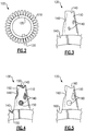
- Figure 2 schematically illustrates one such integrally bladed rotor 100 according to an example.
- the integrally bladed rotor 100 includes multiple airfoil shaped blades 110 protruding radially outward from a hub ring 120. While installed in the engine 20, each of the blades 110 extends radially into a primary flowpath, and rotates about the engine centerline axis.
- the debris When debris is ingested into the engine 20, the debris can pass into the primary flowpath. Due to the rotation of the blades 110 in the primary flowpath, the debris will contact one or more of the blades 110. This contact can cause damage or wear to the blade 110, or blades 110, that are contacted by the debris. When the debris is small enough, the integrally bladed rotor 100 will not become inoperable, and can continue to be used without maintenance. When the debris is large enough, or the wear on the blades 110 is substantial enough, the integrally bladed rotor 100 is no longer suitable for operation and should be removed from the engine.
- integrally bladed rotors 100 Given the expense associated with integrally bladed rotors 100, and similar engine components, it is desirable to repair the integrally bladed rotor 100 whenever possible, such that it is suitable to be returned to an active engine rather than scrapping the component.
- the damage can occur from internal objects that break off within the engine, and impact the integrally bladed rotor airfoils. This is referred to as domestic object damage and can result in similar issues as ingested foreign objects.
- Figure 3 schematically illustrates a portion 130 of the integrally bladed rotor 100 including a substantial amount of wear 140 resulting from utilization of the integrally bladed rotor 100 within a gas turbine engine 20.
- the size and shape of the wear 140 illustrated in Figure 3 is exaggerated for illustrative effect.
- the wear 140 can extend to all of the airfoil blades 110 in a given integrally bladed rotor 100 and the hub ring 120 of the integrally bladed rotor 100 in some examples. In alternative examples, the wear 140 can be limited to a specific localized region.
- a blending operation can be performed on the integrally bladed rotor 100.
- a blending operation uses material removal processes, such as milling or CNC material removal, to remove the damaged portion of the integrally bladed rotor 100 and smooth the resulting voids such that the integrally bladed rotor 100 meets the requirements for operation in the engine.
- Figure 4 schematically illustrates the damaged portion 130 of Figure 2 , with an additional blending mask 150 applied to each of the locations of the wear 140.
- the blending masks 150 are highly exaggerated in scale for explanatory effect.
- the blending masks 150 can be physical masking applied to the actual integrally bladed rotor 100, or shaded colors on computer simulations of the integrally bladed rotor 100. In either case, the blending masks 150 indicate what portions of the material of the blade 110 and/or the hub ring 120 should be removed in order for the blended integrally bladed rotor 100 to be suitable for utilization in the engine 20.
- the blending mask ensures that accurate and consistent blends are made in operations that require or utilize manual removal of material.
- blending mask 150 Once the blending mask 150 has been applied, material is removed using the generally manual material removal operation resulting in a blended blade portion 130 including multiple removed material positions 160, as is illustrated in Figure 5 .
- explicit instructions are derived from the automated process and supplied to a computer controlled machine.
- blending masks are not required as the manual blending operation is replaced by the machine automated process.
- Integrally bladed rotor blends may be by either manual or automated processes, or a combination of those processes. In wholly automated processes, the creation of the mask can be omitted.
- a blend aspect ratio (e.g. a length-depth ratio) is maintained in order to ensure that there is a smooth and gradual transition from the edge of the undamaged blade 110 to the bottom of the deepest portion of the blend, and then back to the undamaged surface of the blade 110 on the other side of the blend.
- a semi-automated blending system is utilized to identify which portions of the integrally bladed rotor 100 should be blended, and by how much.
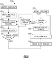
- Figure 6 schematically illustrates a semi-automated blending repair process 600 utilized to repair the article described above.
- a semi-automated process refers to a process in which some portions are performed by an automated system, and some are performed manually.
- the engine component is removed from the engine and manually and/or automatically or some combination thereof inspected in an "Inspect Component" step 610.
- the inspection includes identification of visible damage, as well as using inspection results to determine structural parameters related to blade criteria such as blade frequency characteristics, mistuning characteristics, mode shape characteristics, edge damage, and aeromechanical performance characteristics. These parameters are measured in a non-operating, or cold, state.
- the parameters are provided to a computer system including a finite element model of the ideal component, and a damaged component finite element model is created based on the finite element model of the ideal component and the measured parameters of the damaged component in a "Create Analytical Model" step 620.
- the damaged component finite element model is a modification of the original finite element model that reflects the specific damage or wear present on the damaged component. While some of the parameters related to the blade criteria can be determined in the inspection of the inspected component step 610, the creation of the damaged component finite element model allows the semi-automated process 600 to utilize an analytical model that predicts how the damaged component will react under operating conditions of an engine. As used herein, operating conditions are referred to as "hot" conditions.
- the damaged component finite element model is then provided to an airfoil blend module in a "Calculate Blend Solution" step 630.
- the airfoil blend module determines a suggested blend procedure, including locations of the blend, and depth of each blend by mapping the set of criteria onto the damaged component finite element model during hot conditions and utilizing the set of criteria to determine how and where to dispose the blends. Criteria include, but are not limited to, structural strength and fatigue, aerodynamic efficiency, aerodynamic operability, etc.
- portions of the blend solution can be manually entered by a technician, with the automated process building the solutions based on the initial manual entries.
- a finite element model of the expected resultant component is determined and the structural, aerodynamic, and aeromechanical parameters of the expected resultant component are determined by modeling inclusion of the finite element model of the resultant component in hot conditions in a "Predict Results" step 640.
- the predict results step 640 outputs a set of data indicative of the expected structural, aerodynamic, aeromechanical, and modeshape parameters of the expected resultant component (i.e. the expected repaired component profile) under hot conditions.
- the set of data is compared to pre-established acceptable criteria in a "Criteria Check” step 645.
- the criteria check step 645 can include determining if the operational parameters of the expected resultant component finite element model fall within predefined ranges. If one or more of the criteria do not fall within predefined ranges, the blend solution calculated at step 630 is determined to be invalid.
- the process can either recalculate the blend solution by providing the resultant parameters to the calculate blend solution step 630 or the process 600 can indicate that the component should be held for a rework in a "Hold for Rework" step 647. Once a component has been placed in the hold for rework step 647, it can either be placed in storage until a new repair process is determined, or manually reviewed by a technician for potential blend solutions.
- the blend solution calculated at step 630 is determined to be valid.
- the process 600 creates a blend template in a "Create Blend Template" step 650.
- the system converts the solution determined in the calculate blend solution step 630 into a blend template that can be applied either physically to the damaged component, or to a computer model, such as a CAD model, of the damaged component.
- the blend template further includes instructions and parameters for the automated material removal machine.
- the blend template is transmitted to the material removal machine, and provided to a technician via any computerized output.
- the blend template can be a physical mask made, for example, from a stereolithography material and process is applied to the damaged component. The masking indicates where material should be removed, and how much material should be removed.
- a combination of the physical masking, and a computerized 3D model can be utilized to assist a material removal process performed by a technician.
- the material removal process is performed in a "Blend Component" step 660.
- the material removal process can be manual, automated or a combination of the two.
- an optional verification of the repaired component is performed to verify that the finished product meets the criteria from the first criteria check 645.
- the repaired component is measured, and a finite element model of the repaired component is created in a "Measure / Analyze Results" step 680 in the same manner as in steps 610 and 620.
- the finite element model of the repaired component is then analyzed using the same process as the predict results step 640, and the outputs are checked against the same pre-established criteria to determine if the repaired component is valid. If valid, the process 600 proceeds to the install component step.
- the repaired component is either reblended by returning the process to the calculate blend solution step 630, or is held for reworking at the hold for rework step 647.
- components can be repaired and re-qualified with substantially more repair locations included and / or substantially deeper blends into the airfoil blade 110.
- the semi-automated process described above can allow for an infinite number of wear spot conditions and blending depths, depending on the specific criteria of a given component.
- an integrally bladed rotor repaired according to the semi-automated process described herein can have up to 5% of the blade surface covered in wear spots, and can utilize blends intruding up to 3 mm (0.118 in) into the surface of the airfoil blade 110.
Landscapes
- Engineering & Computer Science (AREA)
- Physics & Mathematics (AREA)
- General Engineering & Computer Science (AREA)
- Mechanical Engineering (AREA)
- Theoretical Computer Science (AREA)
- Geometry (AREA)
- General Physics & Mathematics (AREA)
- Computer Hardware Design (AREA)
- Evolutionary Computation (AREA)
- Fluid Mechanics (AREA)
- Automation & Control Theory (AREA)
- Aviation & Aerospace Engineering (AREA)
- Computational Mathematics (AREA)
- Mathematical Analysis (AREA)
- Mathematical Optimization (AREA)
- Pure & Applied Mathematics (AREA)
- Structures Of Non-Positive Displacement Pumps (AREA)
- Turbine Rotor Nozzle Sealing (AREA)
Applications Claiming Priority (2)
| Application Number | Priority Date | Filing Date | Title |
|---|---|---|---|
| US201862717935P | 2018-08-13 | 2018-08-13 | |
| US16/520,951 US11434764B2 (en) | 2018-08-13 | 2019-07-24 | Process for repairing turbine engine components |
Publications (3)
| Publication Number | Publication Date |
|---|---|
| EP3611337A2 true EP3611337A2 (de) | 2020-02-19 |
| EP3611337A3 EP3611337A3 (de) | 2020-04-29 |
| EP3611337B1 EP3611337B1 (de) | 2023-10-25 |
Family
ID=67587424
Family Applications (1)
| Application Number | Title | Priority Date | Filing Date |
|---|---|---|---|
| EP19190609.8A Active EP3611337B1 (de) | 2018-08-13 | 2019-08-07 | Verfahren zur reparatur von turbinentriebwerkskomponenten |
Country Status (2)
| Country | Link |
|---|---|
| US (1) | US11434764B2 (de) |
| EP (1) | EP3611337B1 (de) |
Cited By (1)
| Publication number | Priority date | Publication date | Assignee | Title |
|---|---|---|---|---|
| WO2023214063A1 (fr) * | 2022-05-06 | 2023-11-09 | École Centrale De Nantes | Procédé et système de réparation d'un objet |
Families Citing this family (17)
| Publication number | Priority date | Publication date | Assignee | Title |
|---|---|---|---|---|
| KR20220141817A (ko) * | 2020-01-20 | 2022-10-20 | 블레이드 다이아그노스틱스 코포레이션 | 블레이드 일체형 로터의 자동 유지를 위한 기술 |
| US11961662B2 (en) * | 2020-07-08 | 2024-04-16 | GE Precision Healthcare LLC | High temperature superconducting current lead assembly for cryogenic apparatus |
| US11905845B1 (en) * | 2021-10-21 | 2024-02-20 | United States Of America As Represented By The Secretary Of The Air Force | Method and system for repairing turbine airfoils |
| US11860060B2 (en) | 2022-04-05 | 2024-01-02 | Rtx Corporation | Integrally bladed rotor analysis and repair systems and methods |
| US20230314341A1 (en) * | 2022-04-05 | 2023-10-05 | Raytheon Technologies Corporation | Data transfer systems and methods for analysis inputs |
| US12037918B2 (en) * | 2022-04-05 | 2024-07-16 | Rtx Corporation | Systems and methods for parameterization of inspected bladed rotor analysis |
| US20230315069A1 (en) * | 2022-04-05 | 2023-10-05 | Raytheon Technologies Corporation | Inspection data management systems and methods |
| US20230315938A1 (en) * | 2022-04-05 | 2023-10-05 | Raytheon Technologies Corporation | Systems and methods for aerodynamic analysis for inspected bladed rotors |
| US12410711B2 (en) | 2022-04-05 | 2025-09-09 | Rtx Corporation | Bladed rotor inspection, analysis and repair systems and methods |
| US20230315949A1 (en) * | 2022-04-05 | 2023-10-05 | Raytheon Technologies Corporation | Systems and methods for structural analysis for inspected bladed rotors |
| US20230315948A1 (en) * | 2022-04-05 | 2023-10-05 | Raytheon Technologies Corporation | Systems and methods for generating blend repair models |
| US12523979B2 (en) | 2022-04-05 | 2026-01-13 | Rtx Corporation | Method of repairing a stack of integrally bladed rotors |
| US20230315937A1 (en) * | 2022-04-05 | 2023-10-05 | Raytheon Technologies Corporation | Partial repair systems and methods for integrally bladed rotors |
| US12318877B2 (en) * | 2022-04-05 | 2025-06-03 | Rtx Corporation | Blend approach based inspection and analysis systems and methods |
| US20230315951A1 (en) * | 2022-04-05 | 2023-10-05 | Raytheon Technologies Corporation | Systems and methods for inspected bladed rotor analysis |
| US12385400B2 (en) | 2022-04-29 | 2025-08-12 | Pratt & Whitney Canada Corp. | Method of manufacturing a mistuned rotor |
| US12524864B2 (en) * | 2023-03-31 | 2026-01-13 | General Electric Company | Component assessment method and apparatus |
Family Cites Families (16)
| Publication number | Priority date | Publication date | Assignee | Title |
|---|---|---|---|---|
| US6606541B2 (en) * | 2001-04-30 | 2003-08-12 | United Technologies Corporation | Automated system for repairing components |
| US6915236B2 (en) * | 2002-11-22 | 2005-07-05 | General Electric Company | Method and system for automated repair design of damaged blades of a compressor or turbine |
| US6910278B2 (en) * | 2003-01-30 | 2005-06-28 | Lockheed Martin Corporation | Apparatus and method for inspecting and marking repair areas on a blade |
| DE102005006414A1 (de) | 2005-02-12 | 2006-08-24 | Mtu Aero Engines Gmbh | Verfahren zum Bearbeiten eines integral beschaufelten Rotors |
| DE102007016369A1 (de) | 2007-04-03 | 2008-10-09 | Rolls-Royce Deutschland Ltd & Co Kg | Verfahren zur Ermittlung der Schaufelverstimmung bei Laufrädern in Integralbauweise |
| DE102008005554A1 (de) | 2008-01-22 | 2009-07-23 | Rolls-Royce Deutschland Ltd & Co Kg | Vorrichtung und Verfahren zur Untersuchung der Oberfläche eines Bauteils |
| EP2361720B1 (de) * | 2010-02-22 | 2012-12-12 | Alstom Technology Ltd | Verfahren zum Reparieren und/oder Überarbeiten eines Bauteils, insbesondere einer Gasturbine |
| US8505384B2 (en) | 2011-02-08 | 2013-08-13 | United Technologies Corporation | Rig for measuring bladed component mistuning |
| US20130180107A1 (en) * | 2012-01-15 | 2013-07-18 | Steven Charles Woods | Method for refurbishing a turbo-machine component |
| DE102012013949A1 (de) | 2012-07-13 | 2014-01-30 | Rolls-Royce Deutschland Ltd & Co Kg | Reparaturverfahren zur Reparatur einer Schaufel einer Gasturbine |
| US20160297044A1 (en) | 2015-04-10 | 2016-10-13 | Rolls-Royce Corporation | Machining parameter control based on acoustic monitoring |
| CN105598450B (zh) | 2016-02-02 | 2017-11-10 | 陕西天元智能再制造股份有限公司 | 一种零部件损伤的激光立体仿形修复方法 |
| US10295436B2 (en) | 2016-03-17 | 2019-05-21 | Honeywell International Inc. | Structured light measuring apparatus and methods |
| US20170370220A1 (en) * | 2016-06-24 | 2017-12-28 | United Technologies Corporation | Customized blend limit for gas turbine engine airfoils |
| US9950815B2 (en) | 2016-07-01 | 2018-04-24 | United Technologies Corporation | Systems and methods for detecting damage |
| EP3417989B1 (de) * | 2017-06-21 | 2023-12-27 | General Electric Technology GmbH | Verfahren zum reparieren einer turbinenkomponente |
-
2019
- 2019-07-24 US US16/520,951 patent/US11434764B2/en active Active
- 2019-08-07 EP EP19190609.8A patent/EP3611337B1/de active Active
Cited By (2)
| Publication number | Priority date | Publication date | Assignee | Title |
|---|---|---|---|---|
| WO2023214063A1 (fr) * | 2022-05-06 | 2023-11-09 | École Centrale De Nantes | Procédé et système de réparation d'un objet |
| FR3135220A1 (fr) * | 2022-05-06 | 2023-11-10 | École Centrale De Nantes | Procédé et système de réparation d’un objet |
Also Published As
| Publication number | Publication date |
|---|---|
| US20200102827A1 (en) | 2020-04-02 |
| EP3611337B1 (de) | 2023-10-25 |
| US11434764B2 (en) | 2022-09-06 |
| EP3611337A3 (de) | 2020-04-29 |
Similar Documents
| Publication | Publication Date | Title |
|---|---|---|
| EP3611337B1 (de) | Verfahren zur reparatur von turbinentriebwerkskomponenten | |
| EP3260656B1 (de) | Verfahren und system zur reparatur eines verdichterschaufelblatts | |
| US11568099B2 (en) | System and process for designing internal components for a gas turbine engine | |
| EP3009599A1 (de) | Gasturbinenbauteil mit filmkühlungsöffnung. | |
| EP3719721B1 (de) | System und verfahren zur planung der flugzeugkomponentenreparatur | |
| US9796055B2 (en) | Turbine case retention hook with insert | |
| US10982552B2 (en) | Gas turbine engine component with film cooling hole | |
| US9869202B2 (en) | Blade outer air seal for a gas turbine engine | |
| EP3819805B1 (de) | Parametrisches verfahren zum entwurf einer komponente | |
| US10167729B2 (en) | Knife edge with increased crack propagation life | |
| US9957814B2 (en) | Gas turbine engine component with film cooling hole with accumulator | |
| EP3428394B1 (de) | Bläserschaufel eines gasturbinenmotors und entwurfverfahren einer bläserschaufel | |
| EP3719256B1 (de) | System und verfahren zur reparatur von flugzeugkomponenten | |
| US20160153865A1 (en) | Gas turbine engine airfoil growth inspection method | |
| US12601295B2 (en) | Support structure for bearing compartment | |
| EP3203032B1 (de) | Methode zur berechnung der querschnittsfläche eines gasturbinenleitapparats und zum ändern der leitschaufeln | |
| EP3059391A1 (de) | Kühlung der turbinenschaufel eines gasturbinenmotors mit vorgelagerter statorschaufel | |
| EP3043030A1 (de) | Verdrehsichere schaufel | |
| Evans et al. | Clearance sensitivity mitigation in small core compressors | |
| US11098591B1 (en) | Turbine blade with contoured fillet | |
| EP3550105A1 (de) | Gasturbinenmotorrotorscheibe |
Legal Events
| Date | Code | Title | Description |
|---|---|---|---|
| PUAI | Public reference made under article 153(3) epc to a published international application that has entered the european phase |
Free format text: ORIGINAL CODE: 0009012 |
|
| STAA | Information on the status of an ep patent application or granted ep patent |
Free format text: STATUS: THE APPLICATION HAS BEEN PUBLISHED |
|
| AK | Designated contracting states |
Kind code of ref document: A2 Designated state(s): AL AT BE BG CH CY CZ DE DK EE ES FI FR GB GR HR HU IE IS IT LI LT LU LV MC MK MT NL NO PL PT RO RS SE SI SK SM TR |
|
| AX | Request for extension of the european patent |
Extension state: BA ME |
|
| PUAL | Search report despatched |
Free format text: ORIGINAL CODE: 0009013 |
|
| AK | Designated contracting states |
Kind code of ref document: A3 Designated state(s): AL AT BE BG CH CY CZ DE DK EE ES FI FR GB GR HR HU IE IS IT LI LT LU LV MC MK MT NL NO PL PT RO RS SE SI SK SM TR |
|
| AX | Request for extension of the european patent |
Extension state: BA ME |
|
| RIC1 | Information provided on ipc code assigned before grant |
Ipc: B23P 6/00 20060101ALI20200321BHEP Ipc: F01D 5/00 20060101AFI20200321BHEP Ipc: G06F 30/17 20200101ALI20200321BHEP Ipc: G06F 30/23 20200101ALI20200321BHEP Ipc: G06Q 10/00 20120101ALI20200321BHEP Ipc: F01D 5/14 20060101ALI20200321BHEP |
|
| STAA | Information on the status of an ep patent application or granted ep patent |
Free format text: STATUS: REQUEST FOR EXAMINATION WAS MADE |
|
| 17P | Request for examination filed |
Effective date: 20201026 |
|
| RBV | Designated contracting states (corrected) |
Designated state(s): AL AT BE BG CH CY CZ DE DK EE ES FI FR GB GR HR HU IE IS IT LI LT LU LV MC MK MT NL NO PL PT RO RS SE SI SK SM TR |
|
| RIC1 | Information provided on ipc code assigned before grant |
Ipc: B23P 6/00 20060101ALI20201222BHEP Ipc: G06Q 10/00 20120101ALI20201222BHEP Ipc: G06F 30/15 20200101ALI20201222BHEP Ipc: F01D 5/00 20060101AFI20201222BHEP Ipc: F01D 5/14 20060101ALI20201222BHEP Ipc: G06F 30/23 20200101ALI20201222BHEP Ipc: G06F 30/17 20200101ALI20201222BHEP |
|
| STAA | Information on the status of an ep patent application or granted ep patent |
Free format text: STATUS: EXAMINATION IS IN PROGRESS |
|
| 17Q | First examination report despatched |
Effective date: 20210211 |
|
| RAP1 | Party data changed (applicant data changed or rights of an application transferred) |
Owner name: RAYTHEON TECHNOLOGIES CORPORATION |
|
| GRAP | Despatch of communication of intention to grant a patent |
Free format text: ORIGINAL CODE: EPIDOSNIGR1 |
|
| STAA | Information on the status of an ep patent application or granted ep patent |
Free format text: STATUS: GRANT OF PATENT IS INTENDED |
|
| INTG | Intention to grant announced |
Effective date: 20230509 |
|
| GRAS | Grant fee paid |
Free format text: ORIGINAL CODE: EPIDOSNIGR3 |
|
| GRAA | (expected) grant |
Free format text: ORIGINAL CODE: 0009210 |
|
| STAA | Information on the status of an ep patent application or granted ep patent |
Free format text: STATUS: THE PATENT HAS BEEN GRANTED |
|
| AK | Designated contracting states |
Kind code of ref document: B1 Designated state(s): AL AT BE BG CH CY CZ DE DK EE ES FI FR GB GR HR HU IE IS IT LI LT LU LV MC MK MT NL NO PL PT RO RS SE SI SK SM TR |
|
| REG | Reference to a national code |
Ref country code: GB Ref legal event code: FG4D |
|
| REG | Reference to a national code |
Ref country code: CH Ref legal event code: EP |
|
| RAP4 | Party data changed (patent owner data changed or rights of a patent transferred) |
Owner name: RTX CORPORATION |
|
| REG | Reference to a national code |
Ref country code: DE Ref legal event code: R096 Ref document number: 602019039929 Country of ref document: DE |
|
| REG | Reference to a national code |
Ref country code: IE Ref legal event code: FG4D |
|
| REG | Reference to a national code |
Ref country code: LT Ref legal event code: MG9D |
|
| REG | Reference to a national code |
Ref country code: NL Ref legal event code: MP Effective date: 20231025 |
|
| REG | Reference to a national code |
Ref country code: AT Ref legal event code: MK05 Ref document number: 1624848 Country of ref document: AT Kind code of ref document: T Effective date: 20231025 |
|
| PG25 | Lapsed in a contracting state [announced via postgrant information from national office to epo] |
Ref country code: NL Free format text: LAPSE BECAUSE OF FAILURE TO SUBMIT A TRANSLATION OF THE DESCRIPTION OR TO PAY THE FEE WITHIN THE PRESCRIBED TIME-LIMIT Effective date: 20231025 |
|
| PG25 | Lapsed in a contracting state [announced via postgrant information from national office to epo] |
Ref country code: GR Free format text: LAPSE BECAUSE OF FAILURE TO SUBMIT A TRANSLATION OF THE DESCRIPTION OR TO PAY THE FEE WITHIN THE PRESCRIBED TIME-LIMIT Effective date: 20240126 |
|
| PG25 | Lapsed in a contracting state [announced via postgrant information from national office to epo] |
Ref country code: IS Free format text: LAPSE BECAUSE OF FAILURE TO SUBMIT A TRANSLATION OF THE DESCRIPTION OR TO PAY THE FEE WITHIN THE PRESCRIBED TIME-LIMIT Effective date: 20240225 |
|
| PG25 | Lapsed in a contracting state [announced via postgrant information from national office to epo] |
Ref country code: LT Free format text: LAPSE BECAUSE OF FAILURE TO SUBMIT A TRANSLATION OF THE DESCRIPTION OR TO PAY THE FEE WITHIN THE PRESCRIBED TIME-LIMIT Effective date: 20231025 |
|
| PG25 | Lapsed in a contracting state [announced via postgrant information from national office to epo] |
Ref country code: AT Free format text: LAPSE BECAUSE OF FAILURE TO SUBMIT A TRANSLATION OF THE DESCRIPTION OR TO PAY THE FEE WITHIN THE PRESCRIBED TIME-LIMIT Effective date: 20231025 |
|
| PG25 | Lapsed in a contracting state [announced via postgrant information from national office to epo] |
Ref country code: ES Free format text: LAPSE BECAUSE OF FAILURE TO SUBMIT A TRANSLATION OF THE DESCRIPTION OR TO PAY THE FEE WITHIN THE PRESCRIBED TIME-LIMIT Effective date: 20231025 |
|
| PG25 | Lapsed in a contracting state [announced via postgrant information from national office to epo] |
Ref country code: LT Free format text: LAPSE BECAUSE OF FAILURE TO SUBMIT A TRANSLATION OF THE DESCRIPTION OR TO PAY THE FEE WITHIN THE PRESCRIBED TIME-LIMIT Effective date: 20231025 Ref country code: IS Free format text: LAPSE BECAUSE OF FAILURE TO SUBMIT A TRANSLATION OF THE DESCRIPTION OR TO PAY THE FEE WITHIN THE PRESCRIBED TIME-LIMIT Effective date: 20240225 Ref country code: GR Free format text: LAPSE BECAUSE OF FAILURE TO SUBMIT A TRANSLATION OF THE DESCRIPTION OR TO PAY THE FEE WITHIN THE PRESCRIBED TIME-LIMIT Effective date: 20240126 Ref country code: ES Free format text: LAPSE BECAUSE OF FAILURE TO SUBMIT A TRANSLATION OF THE DESCRIPTION OR TO PAY THE FEE WITHIN THE PRESCRIBED TIME-LIMIT Effective date: 20231025 Ref country code: BG Free format text: LAPSE BECAUSE OF FAILURE TO SUBMIT A TRANSLATION OF THE DESCRIPTION OR TO PAY THE FEE WITHIN THE PRESCRIBED TIME-LIMIT Effective date: 20240125 Ref country code: AT Free format text: LAPSE BECAUSE OF FAILURE TO SUBMIT A TRANSLATION OF THE DESCRIPTION OR TO PAY THE FEE WITHIN THE PRESCRIBED TIME-LIMIT Effective date: 20231025 Ref country code: PT Free format text: LAPSE BECAUSE OF FAILURE TO SUBMIT A TRANSLATION OF THE DESCRIPTION OR TO PAY THE FEE WITHIN THE PRESCRIBED TIME-LIMIT Effective date: 20240226 |
|
| PG25 | Lapsed in a contracting state [announced via postgrant information from national office to epo] |
Ref country code: SE Free format text: LAPSE BECAUSE OF FAILURE TO SUBMIT A TRANSLATION OF THE DESCRIPTION OR TO PAY THE FEE WITHIN THE PRESCRIBED TIME-LIMIT Effective date: 20231025 Ref country code: RS Free format text: LAPSE BECAUSE OF FAILURE TO SUBMIT A TRANSLATION OF THE DESCRIPTION OR TO PAY THE FEE WITHIN THE PRESCRIBED TIME-LIMIT Effective date: 20231025 Ref country code: PL Free format text: LAPSE BECAUSE OF FAILURE TO SUBMIT A TRANSLATION OF THE DESCRIPTION OR TO PAY THE FEE WITHIN THE PRESCRIBED TIME-LIMIT Effective date: 20231025 Ref country code: NO Free format text: LAPSE BECAUSE OF FAILURE TO SUBMIT A TRANSLATION OF THE DESCRIPTION OR TO PAY THE FEE WITHIN THE PRESCRIBED TIME-LIMIT Effective date: 20240125 Ref country code: LV Free format text: LAPSE BECAUSE OF FAILURE TO SUBMIT A TRANSLATION OF THE DESCRIPTION OR TO PAY THE FEE WITHIN THE PRESCRIBED TIME-LIMIT Effective date: 20231025 Ref country code: HR Free format text: LAPSE BECAUSE OF FAILURE TO SUBMIT A TRANSLATION OF THE DESCRIPTION OR TO PAY THE FEE WITHIN THE PRESCRIBED TIME-LIMIT Effective date: 20231025 |
|
| PG25 | Lapsed in a contracting state [announced via postgrant information from national office to epo] |
Ref country code: DK Free format text: LAPSE BECAUSE OF FAILURE TO SUBMIT A TRANSLATION OF THE DESCRIPTION OR TO PAY THE FEE WITHIN THE PRESCRIBED TIME-LIMIT Effective date: 20231025 |
|
| PG25 | Lapsed in a contracting state [announced via postgrant information from national office to epo] |
Ref country code: CZ Free format text: LAPSE BECAUSE OF FAILURE TO SUBMIT A TRANSLATION OF THE DESCRIPTION OR TO PAY THE FEE WITHIN THE PRESCRIBED TIME-LIMIT Effective date: 20231025 |
|
| REG | Reference to a national code |
Ref country code: DE Ref legal event code: R097 Ref document number: 602019039929 Country of ref document: DE |
|
| PG25 | Lapsed in a contracting state [announced via postgrant information from national office to epo] |
Ref country code: SK Free format text: LAPSE BECAUSE OF FAILURE TO SUBMIT A TRANSLATION OF THE DESCRIPTION OR TO PAY THE FEE WITHIN THE PRESCRIBED TIME-LIMIT Effective date: 20231025 |
|
| PG25 | Lapsed in a contracting state [announced via postgrant information from national office to epo] |
Ref country code: SM Free format text: LAPSE BECAUSE OF FAILURE TO SUBMIT A TRANSLATION OF THE DESCRIPTION OR TO PAY THE FEE WITHIN THE PRESCRIBED TIME-LIMIT Effective date: 20231025 Ref country code: SK Free format text: LAPSE BECAUSE OF FAILURE TO SUBMIT A TRANSLATION OF THE DESCRIPTION OR TO PAY THE FEE WITHIN THE PRESCRIBED TIME-LIMIT Effective date: 20231025 Ref country code: RO Free format text: LAPSE BECAUSE OF FAILURE TO SUBMIT A TRANSLATION OF THE DESCRIPTION OR TO PAY THE FEE WITHIN THE PRESCRIBED TIME-LIMIT Effective date: 20231025 Ref country code: IT Free format text: LAPSE BECAUSE OF FAILURE TO SUBMIT A TRANSLATION OF THE DESCRIPTION OR TO PAY THE FEE WITHIN THE PRESCRIBED TIME-LIMIT Effective date: 20231025 Ref country code: EE Free format text: LAPSE BECAUSE OF FAILURE TO SUBMIT A TRANSLATION OF THE DESCRIPTION OR TO PAY THE FEE WITHIN THE PRESCRIBED TIME-LIMIT Effective date: 20231025 Ref country code: DK Free format text: LAPSE BECAUSE OF FAILURE TO SUBMIT A TRANSLATION OF THE DESCRIPTION OR TO PAY THE FEE WITHIN THE PRESCRIBED TIME-LIMIT Effective date: 20231025 Ref country code: CZ Free format text: LAPSE BECAUSE OF FAILURE TO SUBMIT A TRANSLATION OF THE DESCRIPTION OR TO PAY THE FEE WITHIN THE PRESCRIBED TIME-LIMIT Effective date: 20231025 |
|
| PLBE | No opposition filed within time limit |
Free format text: ORIGINAL CODE: 0009261 |
|
| STAA | Information on the status of an ep patent application or granted ep patent |
Free format text: STATUS: NO OPPOSITION FILED WITHIN TIME LIMIT |
|
| 26N | No opposition filed |
Effective date: 20240726 |
|
| PG25 | Lapsed in a contracting state [announced via postgrant information from national office to epo] |
Ref country code: SI Free format text: LAPSE BECAUSE OF FAILURE TO SUBMIT A TRANSLATION OF THE DESCRIPTION OR TO PAY THE FEE WITHIN THE PRESCRIBED TIME-LIMIT Effective date: 20231025 |
|
| PG25 | Lapsed in a contracting state [announced via postgrant information from national office to epo] |
Ref country code: SI Free format text: LAPSE BECAUSE OF FAILURE TO SUBMIT A TRANSLATION OF THE DESCRIPTION OR TO PAY THE FEE WITHIN THE PRESCRIBED TIME-LIMIT Effective date: 20231025 |
|
| REG | Reference to a national code |
Ref country code: CH Ref legal event code: PL |
|
| PG25 | Lapsed in a contracting state [announced via postgrant information from national office to epo] |
Ref country code: LU Free format text: LAPSE BECAUSE OF NON-PAYMENT OF DUE FEES Effective date: 20240807 |
|
| PG25 | Lapsed in a contracting state [announced via postgrant information from national office to epo] |
Ref country code: CH Free format text: LAPSE BECAUSE OF NON-PAYMENT OF DUE FEES Effective date: 20240831 Ref country code: MC Free format text: LAPSE BECAUSE OF FAILURE TO SUBMIT A TRANSLATION OF THE DESCRIPTION OR TO PAY THE FEE WITHIN THE PRESCRIBED TIME-LIMIT Effective date: 20231025 |
|
| REG | Reference to a national code |
Ref country code: BE Ref legal event code: MM Effective date: 20240831 |
|
| PG25 | Lapsed in a contracting state [announced via postgrant information from national office to epo] |
Ref country code: BE Free format text: LAPSE BECAUSE OF NON-PAYMENT OF DUE FEES Effective date: 20240831 |
|
| PG25 | Lapsed in a contracting state [announced via postgrant information from national office to epo] |
Ref country code: IE Free format text: LAPSE BECAUSE OF NON-PAYMENT OF DUE FEES Effective date: 20240807 |
|
| REG | Reference to a national code |
Ref country code: DE Ref legal event code: R081 Ref document number: 602019039929 Country of ref document: DE Owner name: RTX CORPORATION (N.D.GES.D. STAATES DELAWARE),, US Free format text: FORMER OWNER: RAYTHEON TECHNOLOGIES CORPORATION, FARMINGTON, CT, US |
|
| PG25 | Lapsed in a contracting state [announced via postgrant information from national office to epo] |
Ref country code: FI Free format text: LAPSE BECAUSE OF FAILURE TO SUBMIT A TRANSLATION OF THE DESCRIPTION OR TO PAY THE FEE WITHIN THE PRESCRIBED TIME-LIMIT Effective date: 20231025 |
|
| PGFP | Annual fee paid to national office [announced via postgrant information from national office to epo] |
Ref country code: DE Payment date: 20250724 Year of fee payment: 7 |
|
| PGFP | Annual fee paid to national office [announced via postgrant information from national office to epo] |
Ref country code: GB Payment date: 20250724 Year of fee payment: 7 |
|
| PGFP | Annual fee paid to national office [announced via postgrant information from national office to epo] |
Ref country code: FR Payment date: 20250725 Year of fee payment: 7 |
|
| P01 | Opt-out of the competence of the unified patent court (upc) registered |
Free format text: CASE NUMBER: UPC_APP_0019031_3611337/2025 Effective date: 20251222 |
|
| PG25 | Lapsed in a contracting state [announced via postgrant information from national office to epo] |
Ref country code: CY Free format text: LAPSE BECAUSE OF FAILURE TO SUBMIT A TRANSLATION OF THE DESCRIPTION OR TO PAY THE FEE WITHIN THE PRESCRIBED TIME-LIMIT; INVALID AB INITIO Effective date: 20190807 |
|
| PG25 | Lapsed in a contracting state [announced via postgrant information from national office to epo] |
Ref country code: HU Free format text: LAPSE BECAUSE OF FAILURE TO SUBMIT A TRANSLATION OF THE DESCRIPTION OR TO PAY THE FEE WITHIN THE PRESCRIBED TIME-LIMIT; INVALID AB INITIO Effective date: 20190807 |