EP3611324A1 - Window glass raising / lowering device - Google Patents
Window glass raising / lowering device Download PDFInfo
- Publication number
- EP3611324A1 EP3611324A1 EP19190212.1A EP19190212A EP3611324A1 EP 3611324 A1 EP3611324 A1 EP 3611324A1 EP 19190212 A EP19190212 A EP 19190212A EP 3611324 A1 EP3611324 A1 EP 3611324A1
- Authority
- EP
- European Patent Office
- Prior art keywords
- drum
- housing
- opening portion
- cable
- center axis
- Prior art date
- Legal status (The legal status is an assumption and is not a legal conclusion. Google has not performed a legal analysis and makes no representation as to the accuracy of the status listed.)
- Granted
Links
Images



Classifications
-
- E—FIXED CONSTRUCTIONS
- E05—LOCKS; KEYS; WINDOW OR DOOR FITTINGS; SAFES
- E05F—DEVICES FOR MOVING WINGS INTO OPEN OR CLOSED POSITION; CHECKS FOR WINGS; WING FITTINGS NOT OTHERWISE PROVIDED FOR, CONCERNED WITH THE FUNCTIONING OF THE WING
- E05F15/00—Power-operated mechanisms for wings
- E05F15/60—Power-operated mechanisms for wings using electrical actuators
- E05F15/603—Power-operated mechanisms for wings using electrical actuators using rotary electromotors
- E05F15/665—Power-operated mechanisms for wings using electrical actuators using rotary electromotors for vertically-sliding wings
- E05F15/689—Power-operated mechanisms for wings using electrical actuators using rotary electromotors for vertically-sliding wings specially adapted for vehicle windows
-
- E—FIXED CONSTRUCTIONS
- E05—LOCKS; KEYS; WINDOW OR DOOR FITTINGS; SAFES
- E05Y—INDEXING SCHEME ASSOCIATED WITH SUBCLASSES E05D AND E05F, RELATING TO CONSTRUCTION ELEMENTS, ELECTRIC CONTROL, POWER SUPPLY, POWER SIGNAL OR TRANSMISSION, USER INTERFACES, MOUNTING OR COUPLING, DETAILS, ACCESSORIES, AUXILIARY OPERATIONS NOT OTHERWISE PROVIDED FOR, APPLICATION THEREOF
- E05Y2201/00—Constructional elements; Accessories therefor
- E05Y2201/10—Covers; Housings
-
- E—FIXED CONSTRUCTIONS
- E05—LOCKS; KEYS; WINDOW OR DOOR FITTINGS; SAFES
- E05Y—INDEXING SCHEME ASSOCIATED WITH SUBCLASSES E05D AND E05F, RELATING TO CONSTRUCTION ELEMENTS, ELECTRIC CONTROL, POWER SUPPLY, POWER SIGNAL OR TRANSMISSION, USER INTERFACES, MOUNTING OR COUPLING, DETAILS, ACCESSORIES, AUXILIARY OPERATIONS NOT OTHERWISE PROVIDED FOR, APPLICATION THEREOF
- E05Y2201/00—Constructional elements; Accessories therefor
- E05Y2201/60—Suspension or transmission members; Accessories therefor
- E05Y2201/622—Suspension or transmission members elements
- E05Y2201/658—Members cooperating with flexible elongated pulling elements
- E05Y2201/664—Drums
-
- E—FIXED CONSTRUCTIONS
- E05—LOCKS; KEYS; WINDOW OR DOOR FITTINGS; SAFES
- E05Y—INDEXING SCHEME ASSOCIATED WITH SUBCLASSES E05D AND E05F, RELATING TO CONSTRUCTION ELEMENTS, ELECTRIC CONTROL, POWER SUPPLY, POWER SIGNAL OR TRANSMISSION, USER INTERFACES, MOUNTING OR COUPLING, DETAILS, ACCESSORIES, AUXILIARY OPERATIONS NOT OTHERWISE PROVIDED FOR, APPLICATION THEREOF
- E05Y2800/00—Details, accessories and auxiliary operations not otherwise provided for
- E05Y2800/15—Applicability
- E05Y2800/17—Universally applicable
- E05Y2800/172—Universally applicable on different wing or frame locations
- E05Y2800/174—Universally applicable on different wing or frame locations on the left or right side
-
- E—FIXED CONSTRUCTIONS
- E05—LOCKS; KEYS; WINDOW OR DOOR FITTINGS; SAFES
- E05Y—INDEXING SCHEME ASSOCIATED WITH SUBCLASSES E05D AND E05F, RELATING TO CONSTRUCTION ELEMENTS, ELECTRIC CONTROL, POWER SUPPLY, POWER SIGNAL OR TRANSMISSION, USER INTERFACES, MOUNTING OR COUPLING, DETAILS, ACCESSORIES, AUXILIARY OPERATIONS NOT OTHERWISE PROVIDED FOR, APPLICATION THEREOF
- E05Y2800/00—Details, accessories and auxiliary operations not otherwise provided for
- E05Y2800/40—Physical or chemical protection
- E05Y2800/428—Physical or chemical protection against water or ice
Definitions
- the present invention relates to a window glass raising/lowering device.
- a window glass raising/lowering device that raises and lowers a window glass using a cable is arranged to be laterally symmetrical with respect to a moving direction of a vehicle such that a rail, a drive unit, and the like are arranged at predetermined positions and directions with respect to the moving direction of the vehicle.
- many members relating to routing of the cable such as a drum housing are often used as dedicated parts for right and left depending on a position and a direction.
- Patent Literature 1 JP 2006-076457 A
- the drum housing that accommodates a drum for winding and unwinding the cable is used as a part to be used for the window glass raising/lowering device with the cable.
- the drum housing is provided with a drum accommodating portion accommodating the drum, and the drum accommodating portion is provided with a discharge port to discharge water transmitted from the cable and water entering from above.
- the discharge port to discharge the water is provided below the drum accommodating portion in order to discharge the water accumulated in the drum accommodating portion, and thus, a position thereof is moved upward when the drum housing is laterally reversed.
- water enters the inside of the drum accommodating portion through the upper opening and the water is accumulated in the drum accommodating portion.
- An object of the present invention is to provide a window glass raising/lowering device having a housing that can be shared by devices used on the right and left sides.
- a window glass raising/lowering device of the present invention is a window glass raising/lowering device including: a moving member that moves a window glass; a cable connected to the moving member; a drum that moves the moving member by winding and unwinding the cable; a drive unit that rotates the drum; and a housing that includes: an inner space portion having an accommodating portion in which the drum is accommodated; a cable lead-in/out portion through which the cable is led in and out; and an opening portion that communicates the inner space portion with an outside.
- the opening portion is provided on a radially outer side with respect to a position of a drum center axis.
- the housing has a protruding portion, which extends to an opposite side of the drum in a center axis direction, on a radially outer side of the opening portion with respect to the position of the drum center axis.
- the cable lead-in/out portion has a first cable lead-in/out portion and a second cable lead-in/out portion.
- the first cable lead-in/out portion and the second cable lead-in/out portion are provided in the housing so as to be arranged such that each position of the first cable lead-in/out portion and the second cable lead-in/out portion when the housing is rotated by 180° about the drum center axis becomes line-symmetric with respect to each position of the other cable lead-in/out portion in a state before the rotation by 180°.
- the opening portion has a first opening portion, which is on an upper side with respect to the position of the drum center axis when the first cable lead-in/out portion is on an upper side and on a lower side with respect to the position of the drum center axis when the first cable lead-in/out portion is on a lower side, and a second opening portion which is on an upper side with respect to the position of the drum center axis when the second cable lead-in/out portion is on an upper side and on a lower side with respect to the position of the drum center axis when the second cable lead-in/out portion is on a lower side.
- the protruding portion has a first protruding portion, which is on an upper side of the first opening portion when the first opening portion is on the upper side and on a lower side of the first opening portion when the first opening portion is on the lower side, and a second protruding portion which is on an upper side of the second opening portion when the second opening portion is on the upper side and on a lower side of the second opening portion when the second opening portion is on the lower side.
- the protruding portion has an inner surface and an outer surface.
- the inner surface has a drainage guide portion that guides water, which has moved from the inner space portion of the housing to the opening portion when the protruding portion is on the lower side, to the outside of the housing.
- the outer surface has a weir that moves water adhering to an outer side of the protruding portion downward when the protruding portion is on the upper side.
- the housing of the window glass raising/lowering device used on the right and left sides can be shared by the right and left sides.
- a window glass raising/lowering device according to an embodiment of the present invention will be described below with reference to the drawings. Incidentally, the embodiment to be illustrated hereinafter is merely an example, and the window glass raising/lowering device of the invention is not limited to the following embodiment.
- a window glass raising/lowering device 1 includes: a moving member 2 that moves a window glass W; a cable 3 connected to the moving member 2; a drum 4 that moves the moving member 2 by winding and unwinding the cable 3; a drive unit 5 that rotates the drum 4; and a housing 6 that accommodates the drum 4.
- the window glass raising/lowering device 1 further includes: a guide portion 7 that extends along a moving direction of the moving member 2 and guides the moving member 2; and a direction changing member 8 which is provided at an end of the guide portion 7 to change a direction of the cable 3.
- the window glass raising/lowering device 1 is mounted to a predetermined mounting object, and raises and lowers the window glass W.
- the window glass raising/lowering device 1 of the present embodiment is mounted, for example, to a mounting object such as a door panel of a vehicle body.
- the window glass raising/lowering device 1 may be mounted to another mounting object other than the vehicle body.
- a side to which the window glass W is raised when the window glass raising/lowering device 1 is mounted to the mounting object is called an "upper side”
- a side to which the window glass W is lowered is called a "lower side” regarding the respective members of the window glass raising/lowering device 1 in the present specification.
- the drive unit 5 generates a driving force to rotate the drum 4.
- the drive unit 5 has a driving force generation device such as an electric motor and a manually operated handle.
- the drive unit 5 includes an electric motor 51 and a shaft 52 (see Fig. 6 ) which is connected to the drum 4 and rotates the drum 4 by the driving force of the electric motor 51 as illustrated in Fig. 1 .
- the drive unit 5 is not limited to the illustrated shape or structure as long as it is possible to generate the driving force to rotate the drum 4.
- the drive unit 5 is provided in the vicinity of the center in a longitudinal direction of the guide portion 7 illustrated as a guide rail in the present embodiment, but the position at which the drive unit 5 is provided is not limited.
- the drive unit 5 may be provided at a lower end of the guide portion 7 or the like.
- the drum 4 is rotated in forward and reverse directions about a center axis X of the drum 4 (hereinafter referred to as a drum center axis) by the drive unit 5, thereby moving the moving member 2 by winding and unwinding the cable 3 connected to the drum 4.
- the drum 4 is a substantially cylindrical member, and has an axial hole 41 to which the shaft 52 (see Fig. 6 ) is insertable and which is engaged with the shaft 52.
- the cable 3 is wound around the drum 4 and unwound from the drum 4 along with the rotation of the drum 4.
- the cable 3 is connected to the drum 4 and the moving member 2.
- the moving member 2 connected to the cable 3 is raised and lowered.
- the cable 3 has a first cable 31 and a second cable 32 as illustrated in Fig. 1 .
- One end (not illustrated) of each of the first cable 31 and the second cable 32 is connected to the drum 4.
- Each of other ends 31E and 32E of the first cable 31 and the second cable 32 is connected to the moving member 2.
- the first cable 31 and the second cable 32 extend from the drum 4 toward the direction changing member 8, and are changed in direction by the direction changing member 8 to extend toward the moving member 2.
- the first cable 31 is a raising cable.
- the second cable 32 is a lowering cable.
- the second cable 32 is wound around the drum 4, the moving member 2 is pulled downward by the second cable 32 and moves in a lowering direction. With the movement of the moving member 2 in the lowering direction, the window glass W mounted to the moving member 2 is lowered.
- a publicly-known control cable can be used as the cable 3.
- the first cable 31 and the second cable 32 can be used as inner cables of a control cable. As illustrated in Fig. 1 , the first cable 31 and the second cable 32 may be partially inserted into an outer casing 33 in a routing path.
- the cable 3 is configured using the two cables in the present embodiment, but may be configured using one cable.
- the moving member 2 is operated by the cable 3 to be raised and lowered, thereby raising and lowering the window glass W connected to the moving member 2.
- the window glass W is directly or indirectly mounted to the moving member 2 as illustrated in Fig. 1 .
- the moving member 2 is mounted to the guide portion 7 so as to be movable along the longitudinal direction of the guide portion 7.
- the moving member 2 includes: a first connection portion 21a to which the end 31E of the cable 3 is connected; a second connection portion 21b to which the end 32E of the cable 3 is connected; and a window glass mounting portion 22 to which a lower end of the window glass W is mounted.
- a shape and a structure of the moving member 2 are not limited to those illustrated in the drawings.
- the moving member 2 is guided by the guide portion 7 in the present embodiment, but the moving member 2 may move without being guided by the guide portion 7.
- the housing 6 accommodates the drum 4 to be rotatable.
- the housing 6 is directly or indirectly mounted to a mounting object such as a door panel (not illustrated).
- the window glass raising/lowering device 1 has a base body 9 to which the housing 6 is mounted as illustrated in Figs. 1 , 3 , and 4 .
- the housing 6 is mounted to the mounting object such as the door panel via the base body 9.
- the housing 6 may be directly mounted to the mounting object such as the door panel.
- the mounting object itself such as the door panel serves as the base body.
- the housing 6 includes: an inner space portion 61 (see Fig. 5 ) having an accommodating portion 611 in which the drum 4 is accommodated; a cable lead-in/out portion 62 through which the cable 3 is led in and out; and an opening portion 63 that communicates the inner space portion 61 with the outside.
- the housing 6 includes a protruding portion 64 which extends to an opposite side of the drum 4 in a direction of the drum center axis X, on a radially outer side of the opening portion 63 with respect to a position of the drum center axis X as illustrated in Figs. 2 and 3 .
- the housing 6 has an insertion port 6a (see Figs.
- the housing 6 includes a housing base 65, and the housing base 65 is provided with the accommodating portion 611, the cable lead-in/out portion 62 and the like as illustrated in Fig. 2 .
- the housing base 65 has a connection portion 65a configured to mount the housing 6 to the base body 9.
- the connection portion 65a is fixed to a connected portion 91 provided on the base body 9 by a publicly-known fixing member such as a bolt, a nut, and a screw.
- the inner space portion 61 is a part which forms an inner space provided in the housing 6 that includes the accommodating portion 611 which forms a space in which the drum 4 is accommodated as illustrated in Fig. 5 .
- the inner space portion 61 may include other spaces such as radial spaces S21 and S22 and axial spaces S31 and S32, which will be described later, in addition to an accommodating space S1 of the accommodating portion 611 as illustrated in Fig. 5 .
- the accommodating portion 611 accommodates the drum 4 to be rotatable. As illustrated in Figs. 5 and 6 , the accommodating portion 611 has a circumferential wall 611a opposing an outer circumferential surface 42 (see Fig. 6 ) of the drum 4 and a bottom 611b opposing one end surface 4a of the drum 4. A recess defined by an inner surface IS of the circumferential wall 611a and the bottom 611b serves as the accommodating space S1 in the accommodating portion 611.
- the inner space portion 61 includes not only the accommodating space S1 of the accommodating portion 611 but also the radial spaces S21 and S22, which extend to the radially outer side of the drum 4 to communicate with the accommodating space S1 of the accommodating portion 611, at an end on the base body 9 side in the direction of the drum center axis X as illustrated in Fig. 6 .
- the inner space portion 61 includes the axial spaces S31 and S32, which extend in the direction of the drum center axis X between an inner surface 64a of the protruding portion 64 and an outer surface OS of the circumferential wall 611a, at parts where the opening portion 63 and the protruding portion 64 are provided as illustrated in Figs. 5 and 6 .
- the radial spaces S21 and S22 and the axial spaces S31 and S32 will be described later.
- One side of the inner space portion 61 in the direction of the drum center axis X (a side of the one end surface 4a of the drum 4) is covered by the bottom 611b except for a region of the opening portion 63 as illustrated in Figs. 5 and 6 .
- the other side of the inner space portion 61 in the direction of the drum center axis X (a side of another end surface 4b of the drum 4) opens in the insertion port 6a as illustrated in Fig. 5 in a state where the base body 9 is not mounted.
- the base body 9 has a cover portion 92 that covers the insertion port 6a such that the drum 4 is not detachable from the housing 6 as illustrated in Figs. 3 , 4 and 6 .
- the base body 9 As the base body 9 is mounted to the housing 6, the insertion port 6a is covered by the cover portion 92 in a state where the drum 4 is accommodated in the accommodating portion 611.
- the base body 9 has the mounting portion 93 which mounts the window glass raising/lowering device 1 to a mounting object, such as a door panel, in the present embodiment.
- the mounting portion 93 is formed in an arm shape extending in a direction away from the housing 6 with respect to the plate-shaped cover portion 92.
- the shape of the base body 9 is not particularly limited as long as it is possible to mount the housing 6.
- the cable lead-in/out portion 62 leads the cable 3 to the outside of the housing 6 and leads the cable 3 to the inside of the housing 6.
- the cable lead-in/out portion 62 has a communication passage to communicate the accommodating portion 611 in which the drum 4 is accommodated with the outside of the housing 6, and the cable 3 is led out of the housing 6 and led into the housing 6 through the communication passage.
- the cable lead-in/out portion 62 includes a first cable lead-in/out portion 62a and a second cable lead-in/out portion 62b.
- the outer casing 33 is connected to each of the first and second cable lead-in/out portions 62a and 62b, and the cable 3 is inserted into the outer casing 33 through the first and second cable lead-in/out portions 62a and 62b and extends toward the moving member 2.
- the first cable lead-in/out portion 62a and the second cable lead-in/out portion 62b are provided in the housing 6 so as to be arranged such that each position thereof when the housing 6 is rotated by 180° about the drum center axis X (position illustrated by the two-dot chain line in Fig. 2 ) becomes line-symmetric (hereinafter simply referred to as line symmetry) with respect to a position of the other cable lead-in/out portion in a state before the rotation by 180°(hereinafter simply referred to as line symmetry).
- the same housing 6 can be shared by vertically reversing the housing 6 provided on the left side and the housing 6 provided on the right side.
- the entire housing 6 does not have to be completely line-symmetric as long as the housing 6 includes the first cable lead-in/out portion 62a and the second cable lead-in/out portion 62b arranged with the line symmetry such that the pair of housings arranged at symmetrical positions can be shared.
- the opening portion 63 has a first opening portion 63a and a second opening portion 63b as illustrated in Fig. 2 .
- the first opening portion 63a and the second opening portion 63b are provided on the radially outer side with respect to the position of the drum center axis X.
- the first opening portion 63a is provided on the upper side with respect to the position of the drum center axis X when the first cable lead-in/out portion 62a is on the upper side, and on the lower side with respect to the position of the drum center axis X when the first cable lead-in/out portion 62a is on the lower side.
- the second opening portion 63b is provided on the upper side with respect to the position of the drum center axis X when the second cable lead-in/out portion 62b is on the upper side, and on the lower side with respect to the position of the drum center axis X when the second cable lead-in/out portion 62b is on the lower side.
- any one of the first opening portion 63a and the second opening portion 63b is positioned on the lower side with respect to the position of the drum center axis X. Therefore, when water that has entered the inner space portion 61 flows downward below the drum center axis X, the water can be discharged to the outside of the inner space portion 61 through the opening portion 63.
- the positions of the first opening portion 63a and the second opening portion 63b are not particularly limited as long as it is possible to communicate the inside of the inner space portion 61 with the outside of the inner space portion 61 and to discharge the water having entered the inner space portion 61 to the outside of the inner space portion 61 when positioned on the lower side with respect to the position of drum center axis X.
- the first opening portion 63a and the second opening portion 63b are provided to be opened at a position of a lower end of the circumferential wall 611a when positioned on the lower side with respect to the position of the drum center axis X as illustrated in Fig. 2 .
- the first opening portion 63a and the second opening portion 63b open at a place where the water entered into the inner space portion 61 is collected downward along the circumferential wall 611a. Therefore, the water having entered the inner space portion 61 can be easily discharged.
- Each shape and each size of the first opening portion 63a and the second opening portion 63b are not particularly limited as long as the first opening portion 63a and the second opening portion 63b have predetermined shape and sizes that can smoothly discharge the water having entered the inner space portion 61.
- the first opening portion 63a and the second opening portion 63b are provided such that an upper end and a lower end portion of the bottom 611b are penetrated in the direction of the drum center axis X, and an upper end and a lower end portion of the circumferential wall 611a are penetrated in a radial direction of the drum 4 in the present embodiment as illustrated in Figs. 2 and 5 .
- the protruding portion 64 has a first protruding portion 641 and a second protruding portion 642 as illustrated in Figs. 1 and 2 .
- the first protruding portion 641 extends to the opposite side of the drum 4 in the direction of the center axis X (the left side of the one end surface 4a of the drum 4 in Fig. 6 ) on the radially outer side of the first opening portion 63a with respect to the position of the drum center axis X as illustrated in Fig. 6 . That is, the first protruding portion 641 is provided to cover the first opening portion 63a from the radially outer side of the drum 4 toward a radially inner side.
- the first protruding portion 641 is provided between the first protruding portion 641 and the first opening portion 63a such that a predetermined interval is formed in the radial direction of the drum 4. Although it is sufficient to provide the first protruding portion 641 so as to cover at least a position where the first opening portion 63a is provided, in the direction of the drum center axis X, it is preferable that the first protruding portion 641 extend to the opposite side of the drum 4 beyond the first opening portion 63a in the direction of the drum center axis X.
- the first protruding portion 641 is provided on the upper side of the first opening portion 63a when the first opening portion 63a is on the upper side, and on the lower side of the first opening portion 63a when the first opening portion 63a is on the lower side.
- the first protruding portion 641 covers the first opening portion 63a from the upper side of the first opening portion 63a if the first opening portion 63a is positioned on the upper side with respect to the drum center axis X. If the first opening portion 63a is positioned on the lower side with respect to the drum center axis X, the first protruding portion 641 is arranged below the first opening portion 63a.
- the second protruding portion 642 extends to the opposite side of the drum 4 in the direction of the drum center axis X, on the radially outer side of the second opening portion 63b with respect to the position of the drum center axis X. That is, the second protruding portion 642 is provided to cover the second opening portion 63b from the radially outer side of the drum 4 toward the radially inner side. The second protruding portion 642 is provided between the second protruding portion 642 and the second opening portion 63b such that a predetermined interval is formed in the radial direction of the drum 4.
- the second protruding portion 642 extends so as to cover at least a position where the second opening portion 63b is provided, in the direction of the drum center axis X, it is preferable that the second protruding portion 642 extend to the opposite side of the drum 4 beyond the second opening portion 63b in the direction of the drum center axis X.
- the second protruding portion 642 is provided on the upper side of the second opening portion 63b when the second opening portion 63b is on the upper side, and on the lower side of the second opening portion 63b when the second opening portion 63b is on the lower side.
- the second protruding portion 642 covers the second opening portion 63b from the upper side of the second opening portion 63b if the second opening portion 63b is positioned on the upper side with respect to the drum center axis X. If the second opening portion 63b is positioned on the lower side with respect to the drum center axis X, the second protruding portion 642 is arranged below the second opening portion 63b.
- Each of the first protruding portion 641 and the second protruding portion 642 has the inner surface 64a and an outer surface 64b as illustrated in Fig. 2 .
- the inner surface 64a is a surface of the protruding portion 64 that faces a surface on the side of the opening portion 63, that is, a surface that faces the outer circumferential surface 42 of the drum 4.
- the outer surface 64b is a surface of the protruding portion 64 on the side opposite to the inner surface 64a, that is, the surface of the protruding portion 64 that is farther from the drum center axis X.
- the inner surface 64a has a drainage guide portion G that guides water, which has moved from the inner space portion 61 of the housing 6 to the opening portion 63 when the protruding portion 64 is on the lower side, to the outside of the housing 6 as illustrated in Fig. 2 .
- the outer surface 64b has a weir D that moves water adhering to the outer side of the protruding portion 64 downward when the protruding portion 64 is on the upper side as illustrated in Fig. 2 .
- the drainage guide portion G guides the water to the outside of the housing 6.
- the drainage guide portion G prevents water from being accumulated in the inner space portion 61 and the housing 6.
- the drainage guide portion G is provided with a guide portion that guides water from the opening portion 63 to a side away from the opening portion 63, and keeps the water away from the adjacent opening portion 63.
- the guide portion has, for example, a concave shape and is provided such that water moves downward.
- the weir D causes water flowing from the upper side of the protruding portion 64 to flow downward along the weir D so as to deviate from the opening portion 63, and prevents water from entering the opening portion 63 positioned below the protruding portion 64.
- the window glass raising/lowering device 1 of the present embodiment is provided in the housing 6 with the arrangement in which the first cable lead-in/out portion 62a and the second cable lead-in/out portion 62b are line-symmetric.
- the same housing 6 can be shared by vertically reversing the housing 6 provided on the left side and the housing 6 provided on the right side in the mounting object for which the pair of the housings 6 are provided at symmetrical positions.
- the housing 6 includes the first opening portion 63a and the second opening portion 63b that communicate the inside of the inner space portion 61 with the outside of the inner space portion 61.
- the water discharged from the opening portion 63 on the lower side is guided to the outside of the housing 6 by the drainage guide portion G of the protruding portion 64 positioned on the lower side between the first protruding portion 641 and the second protruding portion 642.
- the opening portion 63 is provided on the upper side of the inner space portion 61, but water is prevented from entering from the opening portion 63 on the upper side by the weir D of the upper protruding portion 64 on the upper side of the opening portion 63 positioned on the upper side.
- the window glass raising/lowering device 1 of the present embodiment can share the housing 6 on the right and left sides by vertically reversing the housing 6 and can suppress the entry and accumulation of water inside the inner space portion 61 of the housing 6.
- the housing 6 is provided on the left side of the vehicle such that the first cable lead-in/out portion 62a, the first opening portion 63a, and the first protruding portion 641 are on the upper side.
- the same housing 6 is provided to be vertically reversed from the housing 6 on the left side such that the second cable lead-in/out portion 62b, the second opening portion 63b, and the second protruding portion 642 are on the upper side.
- the housings 6 can be arranged to be laterally symmetric with respect to a moving direction of the vehicle on the right and left sides of the vehicle.
- the water ran along the cable 3 and the water entering from the upper side of the housing 6 are prevented from entering the inner space portion 61 through the first opening portion 63a by the weir D of the outer surface 64b of the first protruding portion 641.
- the first protruding portion 641 functioning as the weir D on the left side promotes the discharge of water flowing out of the first opening portion 63a by the drainage guide portion G of the inner surface 64a on the right side of the vehicle.
- the drainage guide portion G of the inner surface 64a of the second protruding portion 642 promotes the discharge of water flowing out of the second opening portion 63b.
- the second protruding portion 642 functioning as the drainage guide portion G on the left side prevents water from entering the inner space portion 61 from the second opening portion 63b by the weir D of the outer surface 64b on the right side of the vehicle.
- the first opening portion 63a and the second opening portion 63b are formed, and an air flow from the upper opening portion 63 toward the lower opening portion 63 is likely to occur inside the inner space portion 61 in the present embodiment. Therefore, the flow of water inside the inner space portion 61 is smoother than that in the case where there is only one opening portion, and the drainage from the inner space portion 61 is further promoted.
- the protruding portion 64 is provided so as to protrude outward with respect to the drum center axis X as illustrated in Fig. 2 . Since the protruding portion 64 protrudes outward, the weir D having an inclined surface, which has a downward slope with respect to a top 64c, is formed on both sides of the top 64c of the protruding portion 64 in the circumferential direction of the drum 4, on the outer surface 64b of the protruding portion 64 when the protruding portion 64 is arranged on the upper side as illustrated in Fig. 2 .
- the weir D is provided with a guide portion that guides water from above to a side away from the opening portion 63, and keeps water away from the adjacent opening portion 63.
- the guide portion has, for example, a shape that is convex upward.
- the protruding portion 64 extends to the radially outer side of the drum 4 from the circumferential wall 611a and covers the opening portion 63 in an arched shape such that the opening portion 63 is sandwiched in the circumferential direction of the drum 4 as illustrated in Fig. 2 .
- the protruding portion 64 does not necessarily extend from the circumferential wall 611a, and may extend from the housing base 65 in the direction of the drum center axis X independently of the circumferential wall 611a.
- the base body 9 has a discharge portion 94 which forms, together with the housing 6, a hole capable of discharging water from the inner space portion 61 of the housing 6 in the present embodiment as illustrated in Fig. 6
- the discharge portion 94 is a hole to discharge the water which has entered the inner space portion 61 from the base body 9 side.
- the discharge portion 94 penetrates through the base body 9 (cover portion 92) in a lower part of the inner space portion 61 to communicate the inside of the inner space portion 61 with the outside. Since the discharge portion 94 is provided, the water having moved toward the base body 9 side can be discharged from the discharge portion 94 inside the inner space portion 61 without being directed to the opening portion 63. Therefore, it is possible to further suppress that water from being stored in inner space portion 61.
- the inner space portion 61 has the radial space (a first radial space) S21, which extends to the radially outer side of the drum 4 so as to communicate with the accommodating space S1 of the accommodating portion 611, at the end on the base body 9 side in the direction of the drum center axis X as illustrated in Figs. 5 and 6 .
- the radial space S21 forms a recess downward on the lower side of the inner space portion 61, and functions as a water collecting portion to collect water directed toward the base body 9 side of the inner space portion 61 in the direction of the drum center axis X.
- the discharge portion 94 is provided at a position corresponding to the radial space S21, and the water flowing into the radial space S21 is discharged from the inner space portion 61 through the discharge portion 94 by being communicated the radial space S21 with the discharge portion 94.
- the radial space (a second radial space) S22 extending to the radially outer side of the drum 4 is also provided on the upper side of the inner space portion 61 in the present embodiment.
- the upper radial space S22 is covered by the cover portion 92 of the base body 9, and water does not enter from the upper side of the inner space portion 61 through the base body 9.
- the radial space S22 when the radial space S22 is arranged on the lower side, the radial space S22 communicates with the discharge portion 94 of the base body 9, and the water flowing into the radial space S22 is discharged from the inner space portion 61 through the discharge portion 94.
- the inner space portion 61 has the axial space (a first axial space) S31 extending in the direction of the drum center axis X between the inner surface 64a of the protruding portion 64 and the outer surface OS of the circumferential wall 611a, in a part where the lower opening portion 63 and the protruding portion 64 are provided, in the present embodiment as illustrated in Figs. 5 and 6 .
- the axial space S31 communicates with the radial space S21. Water discharged from the inner space portion 61 through the lower opening portion 63 moves to the weir D of the lower protruding portion 64.
- the water having moved to the weir D moves not only in the direction away from the base body 9 in the direction of the drum center axis X but also to the radial space S21. Therefore, the water having moved to the weir D can move to both the sides in the direction of the drum center axis X, and water can also be discharged directly from the weir D, and water can also be discharged through the axial space S31, the radial space S21, and the discharge portion 94. Thus, even if there is a large amount of water that has entered, the water can be reliably discharged.
- the axial space (a second axial space) S32 which extends in the direction of the drum center axis X, is provided between the inner surface 64a of the protruding portion 64 and the outer surface OS of the circumferential wall 611a even on the upper side of the inner space portion 61 in the present embodiment.
- the axial space S32 communicates with the radial space S22.
- the water can also be directly discharged from the weir D, and the water can be discharged through the axial space S32, the radial space S22, and the discharge portion 94, as in the case of the axial space S31.
Landscapes
- Window Of Vehicle (AREA)
- Specific Sealing Or Ventilating Devices For Doors And Windows (AREA)
- Power-Operated Mechanisms For Wings (AREA)
Abstract
Description
- The present invention relates to a window glass raising/lowering device.
- A window glass raising/lowering device (see Patent Literature 1) that raises and lowers a window glass using a cable is arranged to be laterally symmetrical with respect to a moving direction of a vehicle such that a rail, a drive unit, and the like are arranged at predetermined positions and directions with respect to the moving direction of the vehicle. Thus, many members relating to routing of the cable such as a drum housing are often used as dedicated parts for right and left depending on a position and a direction.
- Patent Literature 1:
JP 2006-076457 A - The drum housing that accommodates a drum for winding and unwinding the cable is used as a part to be used for the window glass raising/lowering device with the cable. The drum housing is provided with a drum accommodating portion accommodating the drum, and the drum accommodating portion is provided with a discharge port to discharge water transmitted from the cable and water entering from above. The discharge port to discharge the water is provided below the drum accommodating portion in order to discharge the water accumulated in the drum accommodating portion, and thus, a position thereof is moved upward when the drum housing is laterally reversed. When there is an opening at an upper side of the drum housing, water enters the inside of the drum accommodating portion through the upper opening and the water is accumulated in the drum accommodating portion.
- That is, it is difficult to share the housing, provided with the discharge port for the water on the lower side, directly on the right and left side.
- An object of the present invention is to provide a window glass raising/lowering device having a housing that can be shared by devices used on the right and left sides.
- A window glass raising/lowering device of the present invention is a window glass raising/lowering device including: a moving member that moves a window glass; a cable connected to the moving member; a drum that moves the moving member by winding and unwinding the cable; a drive unit that rotates the drum; and a housing that includes: an inner space portion having an accommodating portion in which the drum is accommodated; a cable lead-in/out portion through which the cable is led in and out; and an opening portion that communicates the inner space portion with an outside. The opening portion is provided on a radially outer side with respect to a position of a drum center axis. The housing has a protruding portion, which extends to an opposite side of the drum in a center axis direction, on a radially outer side of the opening portion with respect to the position of the drum center axis. The cable lead-in/out portion has a first cable lead-in/out portion and a second cable lead-in/out portion. The first cable lead-in/out portion and the second cable lead-in/out portion are provided in the housing so as to be arranged such that each position of the first cable lead-in/out portion and the second cable lead-in/out portion when the housing is rotated by 180° about the drum center axis becomes line-symmetric with respect to each position of the other cable lead-in/out portion in a state before the rotation by 180°. The opening portion has a first opening portion, which is on an upper side with respect to the position of the drum center axis when the first cable lead-in/out portion is on an upper side and on a lower side with respect to the position of the drum center axis when the first cable lead-in/out portion is on a lower side, and a second opening portion which is on an upper side with respect to the position of the drum center axis when the second cable lead-in/out portion is on an upper side and on a lower side with respect to the position of the drum center axis when the second cable lead-in/out portion is on a lower side. The protruding portion has a first protruding portion, which is on an upper side of the first opening portion when the first opening portion is on the upper side and on a lower side of the first opening portion when the first opening portion is on the lower side, and a second protruding portion which is on an upper side of the second opening portion when the second opening portion is on the upper side and on a lower side of the second opening portion when the second opening portion is on the lower side. The protruding portion has an inner surface and an outer surface. The inner surface has a drainage guide portion that guides water, which has moved from the inner space portion of the housing to the opening portion when the protruding portion is on the lower side, to the outside of the housing. The outer surface has a weir that moves water adhering to an outer side of the protruding portion downward when the protruding portion is on the upper side.
- According to the present invention, the housing of the window glass raising/lowering device used on the right and left sides can be shared by the right and left sides.
-
-
Fig. 1 is a schematic view illustrating a window glass raising/lowering device according to an embodiment of the present invention. -
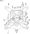
Fig. 2 is a schematic front view illustrating a housing of the window glass raising/lowering device ofFig. 1 . -
Fig. 3 is a exploded perspective view of the window glass raising/lowering device ofFig. 1 in which the housing and a base body are separated. -
Fig. 4 is a exploded perspective view of the window glass raising/lowering device ofFig. 1 viewed from a side of an insertion port of the housing. -
Fig. 5 is a schematic cross-sectional view cut along a line B-B inFig. 2 . -
Fig. 6 is a cross-sectional view taken along a line A-A inFig. 1 . - A window glass raising/lowering device according to an embodiment of the present invention will be described below with reference to the drawings. Incidentally, the embodiment to be illustrated hereinafter is merely an example, and the window glass raising/lowering device of the invention is not limited to the following embodiment.
- As illustrated in
Fig. 1 , a window glass raising/loweringdevice 1 includes: a moving member 2 that moves a window glass W; a cable 3 connected to the moving member 2; adrum 4 that moves the moving member 2 by winding and unwinding the cable 3; adrive unit 5 that rotates thedrum 4; and ahousing 6 that accommodates thedrum 4. In the present embodiment, the window glass raising/loweringdevice 1 further includes: aguide portion 7 that extends along a moving direction of the moving member 2 and guides the moving member 2; and adirection changing member 8 which is provided at an end of theguide portion 7 to change a direction of the cable 3. - The window glass raising/lowering
device 1 is mounted to a predetermined mounting object, and raises and lowers the window glass W. The window glass raising/loweringdevice 1 of the present embodiment is mounted, for example, to a mounting object such as a door panel of a vehicle body. The window glass raising/loweringdevice 1 may be mounted to another mounting object other than the vehicle body. Incidentally, a side to which the window glass W is raised when the window glass raising/loweringdevice 1 is mounted to the mounting object is called an "upper side", and a side to which the window glass W is lowered is called a "lower side" regarding the respective members of the window glass raising/loweringdevice 1 in the present specification. - The
drive unit 5 generates a driving force to rotate thedrum 4. Thedrive unit 5 has a driving force generation device such as an electric motor and a manually operated handle. In the present embodiment, thedrive unit 5 includes anelectric motor 51 and a shaft 52 (seeFig. 6 ) which is connected to thedrum 4 and rotates thedrum 4 by the driving force of theelectric motor 51 as illustrated inFig. 1 . Incidentally, thedrive unit 5 is not limited to the illustrated shape or structure as long as it is possible to generate the driving force to rotate thedrum 4. Although thedrive unit 5 is provided in the vicinity of the center in a longitudinal direction of theguide portion 7 illustrated as a guide rail in the present embodiment, but the position at which thedrive unit 5 is provided is not limited. For example, thedrive unit 5 may be provided at a lower end of theguide portion 7 or the like. - The
drum 4 is rotated in forward and reverse directions about a center axis X of the drum 4 (hereinafter referred to as a drum center axis) by thedrive unit 5, thereby moving the moving member 2 by winding and unwinding the cable 3 connected to thedrum 4. In the present embodiment, thedrum 4 is a substantially cylindrical member, and has anaxial hole 41 to which the shaft 52 (seeFig. 6 ) is insertable and which is engaged with theshaft 52. When theshaft 52 is rotated by the driving force of thedrive unit 5, thedrum 4 is rotated as illustrated inFigs. 4 and6 . - The cable 3 is wound around the
drum 4 and unwound from thedrum 4 along with the rotation of thedrum 4. The cable 3 is connected to thedrum 4 and the moving member 2. As the cable 3 is operated by the rotation of thedrum 4, the moving member 2 connected to the cable 3 is raised and lowered. In the present embodiment, the cable 3 has afirst cable 31 and a second cable 32 as illustrated inFig. 1 . One end (not illustrated) of each of thefirst cable 31 and the second cable 32 is connected to thedrum 4. Each ofother ends first cable 31 and the second cable 32 is connected to the moving member 2. In the present embodiment, thefirst cable 31 and the second cable 32 extend from thedrum 4 toward thedirection changing member 8, and are changed in direction by thedirection changing member 8 to extend toward the moving member 2. In the present embodiment, thefirst cable 31 is a raising cable. When thefirst cable 31 is wound around thedrum 4, the moving member 2 is pulled upward by thefirst cable 31 and moves in a raising direction. With the movement of the moving member 2 in the raising direction, the window glass W mounted to the moving member 2 is raised. The second cable 32 is a lowering cable. When the second cable 32 is wound around thedrum 4, the moving member 2 is pulled downward by the second cable 32 and moves in a lowering direction. With the movement of the moving member 2 in the lowering direction, the window glass W mounted to the moving member 2 is lowered. Incidentally, a publicly-known control cable can be used as the cable 3. For example, thefirst cable 31 and the second cable 32 can be used as inner cables of a control cable. As illustrated inFig. 1 , thefirst cable 31 and the second cable 32 may be partially inserted into anouter casing 33 in a routing path. In addition, the cable 3 is configured using the two cables in the present embodiment, but may be configured using one cable. - The moving member 2 is operated by the cable 3 to be raised and lowered, thereby raising and lowering the window glass W connected to the moving member 2. The window glass W is directly or indirectly mounted to the moving member 2 as illustrated in
Fig. 1 . In the present embodiment, the moving member 2 is mounted to theguide portion 7 so as to be movable along the longitudinal direction of theguide portion 7. As illustrated inFig. 1 , the moving member 2 includes: afirst connection portion 21a to which theend 31E of the cable 3 is connected; asecond connection portion 21b to which theend 32E of the cable 3 is connected; and a windowglass mounting portion 22 to which a lower end of the window glass W is mounted. Incidentally, a shape and a structure of the moving member 2 are not limited to those illustrated in the drawings. In addition, the moving member 2 is guided by theguide portion 7 in the present embodiment, but the moving member 2 may move without being guided by theguide portion 7. - The
housing 6 accommodates thedrum 4 to be rotatable. Thehousing 6 is directly or indirectly mounted to a mounting object such as a door panel (not illustrated). In the present embodiment, the window glass raising/loweringdevice 1 has abase body 9 to which thehousing 6 is mounted as illustrated inFigs. 1 ,3 , and4 . In the present embodiment, thehousing 6 is mounted to the mounting object such as the door panel via thebase body 9. Incidentally, thehousing 6 may be directly mounted to the mounting object such as the door panel. In such a case, the mounting object itself such as the door panel serves as the base body. - As illustrated in
Fig. 2 , thehousing 6 includes: an inner space portion 61 (seeFig. 5 ) having anaccommodating portion 611 in which thedrum 4 is accommodated; a cable lead-in/outportion 62 through which the cable 3 is led in and out; and anopening portion 63 that communicates theinner space portion 61 with the outside. In addition, thehousing 6 includes a protrudingportion 64 which extends to an opposite side of thedrum 4 in a direction of the drum center axis X, on a radially outer side of the openingportion 63 with respect to a position of the drum center axis X as illustrated inFigs. 2 and3 . Thehousing 6 has aninsertion port 6a (seeFigs. 4 and5 ) through which thedrum 4 can be inserted into theinner space portion 61. In the present embodiment, thehousing 6 includes ahousing base 65, and thehousing base 65 is provided with theaccommodating portion 611, the cable lead-in/outportion 62 and the like as illustrated inFig. 2 . Thehousing base 65 has aconnection portion 65a configured to mount thehousing 6 to thebase body 9. Theconnection portion 65a is fixed to a connectedportion 91 provided on thebase body 9 by a publicly-known fixing member such as a bolt, a nut, and a screw. - The
inner space portion 61 is a part which forms an inner space provided in thehousing 6 that includes theaccommodating portion 611 which forms a space in which thedrum 4 is accommodated as illustrated inFig. 5 . Theinner space portion 61 may include other spaces such as radial spaces S21 and S22 and axial spaces S31 and S32, which will be described later, in addition to an accommodating space S1 of theaccommodating portion 611 as illustrated inFig. 5 . - The
accommodating portion 611 accommodates thedrum 4 to be rotatable. As illustrated inFigs. 5 and6 , theaccommodating portion 611 has acircumferential wall 611a opposing an outer circumferential surface 42 (seeFig. 6 ) of thedrum 4 and a bottom 611b opposing oneend surface 4a of thedrum 4. A recess defined by an inner surface IS of thecircumferential wall 611a and the bottom 611b serves as the accommodating space S1 in theaccommodating portion 611. - In the present embodiment, the
inner space portion 61 includes not only the accommodating space S1 of theaccommodating portion 611 but also the radial spaces S21 and S22, which extend to the radially outer side of thedrum 4 to communicate with the accommodating space S1 of theaccommodating portion 611, at an end on thebase body 9 side in the direction of the drum center axis X as illustrated inFig. 6 . In addition, theinner space portion 61 includes the axial spaces S31 and S32, which extend in the direction of the drum center axis X between aninner surface 64a of the protrudingportion 64 and an outer surface OS of thecircumferential wall 611a, at parts where the openingportion 63 and the protrudingportion 64 are provided as illustrated inFigs. 5 and6 . The radial spaces S21 and S22 and the axial spaces S31 and S32 will be described later. - One side of the
inner space portion 61 in the direction of the drum center axis X (a side of the oneend surface 4a of the drum 4) is covered by the bottom 611b except for a region of the openingportion 63 as illustrated inFigs. 5 and6 . The other side of theinner space portion 61 in the direction of the drum center axis X (a side of anotherend surface 4b of the drum 4) opens in theinsertion port 6a as illustrated inFig. 5 in a state where thebase body 9 is not mounted. In the present embodiment, thebase body 9 has acover portion 92 that covers theinsertion port 6a such that thedrum 4 is not detachable from thehousing 6 as illustrated inFigs. 3 ,4 and6 . As thebase body 9 is mounted to thehousing 6, theinsertion port 6a is covered by thecover portion 92 in a state where thedrum 4 is accommodated in theaccommodating portion 611. Incidentally, thebase body 9 has the mountingportion 93 which mounts the window glass raising/loweringdevice 1 to a mounting object, such as a door panel, in the present embodiment. The mountingportion 93 is formed in an arm shape extending in a direction away from thehousing 6 with respect to the plate-shapedcover portion 92. Incidentally, the shape of thebase body 9 is not particularly limited as long as it is possible to mount thehousing 6. - The cable lead-in/out
portion 62 leads the cable 3 to the outside of thehousing 6 and leads the cable 3 to the inside of thehousing 6. The cable lead-in/outportion 62 has a communication passage to communicate theaccommodating portion 611 in which thedrum 4 is accommodated with the outside of thehousing 6, and the cable 3 is led out of thehousing 6 and led into thehousing 6 through the communication passage. As illustrated inFigs. 1 and2 , the cable lead-in/outportion 62 includes a first cable lead-in/outportion 62a and a second cable lead-in/outportion 62b. In the present embodiment, theouter casing 33 is connected to each of the first and second cable lead-in/outportions outer casing 33 through the first and second cable lead-in/outportions - The first cable lead-in/out
portion 62a and the second cable lead-in/outportion 62b are provided in thehousing 6 so as to be arranged such that each position thereof when thehousing 6 is rotated by 180° about the drum center axis X (position illustrated by the two-dot chain line inFig. 2 ) becomes line-symmetric (hereinafter simply referred to as line symmetry) with respect to a position of the other cable lead-in/out portion in a state before the rotation by 180°(hereinafter simply referred to as line symmetry). Therefore, for example, in a mounting object for which a pair of thehousings 6 are provided at symmetrical positions, such as a left door and a right door of a vehicle, thesame housing 6 can be shared by vertically reversing thehousing 6 provided on the left side and thehousing 6 provided on the right side. Incidentally, theentire housing 6 does not have to be completely line-symmetric as long as thehousing 6 includes the first cable lead-in/outportion 62a and the second cable lead-in/outportion 62b arranged with the line symmetry such that the pair of housings arranged at symmetrical positions can be shared. - The opening
portion 63 has afirst opening portion 63a and asecond opening portion 63b as illustrated inFig. 2 . Thefirst opening portion 63a and thesecond opening portion 63b are provided on the radially outer side with respect to the position of the drum center axis X. Thefirst opening portion 63a is provided on the upper side with respect to the position of the drum center axis X when the first cable lead-in/outportion 62a is on the upper side, and on the lower side with respect to the position of the drum center axis X when the first cable lead-in/outportion 62a is on the lower side. In addition, thesecond opening portion 63b is provided on the upper side with respect to the position of the drum center axis X when the second cable lead-in/outportion 62b is on the upper side, and on the lower side with respect to the position of the drum center axis X when the second cable lead-in/outportion 62b is on the lower side. - As a result, any one of the
first opening portion 63a and thesecond opening portion 63b is positioned on the lower side with respect to the position of the drum center axis X. Therefore, when water that has entered theinner space portion 61 flows downward below the drum center axis X, the water can be discharged to the outside of theinner space portion 61 through the openingportion 63. - The positions of the
first opening portion 63a and thesecond opening portion 63b are not particularly limited as long as it is possible to communicate the inside of theinner space portion 61 with the outside of theinner space portion 61 and to discharge the water having entered theinner space portion 61 to the outside of theinner space portion 61 when positioned on the lower side with respect to the position of drum center axis X. In the present embodiment, thefirst opening portion 63a and thesecond opening portion 63b are provided to be opened at a position of a lower end of thecircumferential wall 611a when positioned on the lower side with respect to the position of the drum center axis X as illustrated inFig. 2 . In this case, thefirst opening portion 63a and thesecond opening portion 63b open at a place where the water entered into theinner space portion 61 is collected downward along thecircumferential wall 611a. Therefore, the water having entered theinner space portion 61 can be easily discharged. - Each shape and each size of the
first opening portion 63a and thesecond opening portion 63b are not particularly limited as long as thefirst opening portion 63a and thesecond opening portion 63b have predetermined shape and sizes that can smoothly discharge the water having entered theinner space portion 61. Incidentally, thefirst opening portion 63a and thesecond opening portion 63b are provided such that an upper end and a lower end portion of the bottom 611b are penetrated in the direction of the drum center axis X, and an upper end and a lower end portion of thecircumferential wall 611a are penetrated in a radial direction of thedrum 4 in the present embodiment as illustrated inFigs. 2 and5 . - The protruding
portion 64 has a first protrudingportion 641 and a second protrudingportion 642 as illustrated inFigs. 1 and2 . The first protrudingportion 641 extends to the opposite side of thedrum 4 in the direction of the center axis X (the left side of the oneend surface 4a of thedrum 4 inFig. 6 ) on the radially outer side of thefirst opening portion 63a with respect to the position of the drum center axis X as illustrated inFig. 6 . That is, the first protrudingportion 641 is provided to cover thefirst opening portion 63a from the radially outer side of thedrum 4 toward a radially inner side. The first protrudingportion 641 is provided between the first protrudingportion 641 and thefirst opening portion 63a such that a predetermined interval is formed in the radial direction of thedrum 4. Although it is sufficient to provide the first protrudingportion 641 so as to cover at least a position where thefirst opening portion 63a is provided, in the direction of the drum center axis X, it is preferable that the first protrudingportion 641 extend to the opposite side of thedrum 4 beyond thefirst opening portion 63a in the direction of the drum center axis X. - The first protruding
portion 641 is provided on the upper side of thefirst opening portion 63a when thefirst opening portion 63a is on the upper side, and on the lower side of thefirst opening portion 63a when thefirst opening portion 63a is on the lower side. When the window glass raising/loweringdevice 1 is mounted to a mounting object, the first protrudingportion 641 covers thefirst opening portion 63a from the upper side of thefirst opening portion 63a if thefirst opening portion 63a is positioned on the upper side with respect to the drum center axis X. If thefirst opening portion 63a is positioned on the lower side with respect to the drum center axis X, the first protrudingportion 641 is arranged below thefirst opening portion 63a. - As illustrated in
Fig. 6 , the second protrudingportion 642 extends to the opposite side of thedrum 4 in the direction of the drum center axis X, on the radially outer side of thesecond opening portion 63b with respect to the position of the drum center axis X. That is, the second protrudingportion 642 is provided to cover thesecond opening portion 63b from the radially outer side of thedrum 4 toward the radially inner side. The second protrudingportion 642 is provided between the second protrudingportion 642 and thesecond opening portion 63b such that a predetermined interval is formed in the radial direction of thedrum 4. Although it is sufficient for the second protrudingportion 642 to extend so as to cover at least a position where thesecond opening portion 63b is provided, in the direction of the drum center axis X, it is preferable that the second protrudingportion 642 extend to the opposite side of thedrum 4 beyond thesecond opening portion 63b in the direction of the drum center axis X. - The second protruding
portion 642 is provided on the upper side of thesecond opening portion 63b when thesecond opening portion 63b is on the upper side, and on the lower side of thesecond opening portion 63b when thesecond opening portion 63b is on the lower side. When the window glass raising/loweringdevice 1 is mounted to a mounting object, the second protrudingportion 642 covers thesecond opening portion 63b from the upper side of thesecond opening portion 63b if thesecond opening portion 63b is positioned on the upper side with respect to the drum center axis X. If thesecond opening portion 63b is positioned on the lower side with respect to the drum center axis X, the second protrudingportion 642 is arranged below thesecond opening portion 63b. - Each of the first protruding
portion 641 and the second protrudingportion 642 has theinner surface 64a and anouter surface 64b as illustrated inFig. 2 . Theinner surface 64a is a surface of the protrudingportion 64 that faces a surface on the side of the openingportion 63, that is, a surface that faces the outercircumferential surface 42 of thedrum 4. In addition, theouter surface 64b is a surface of the protrudingportion 64 on the side opposite to theinner surface 64a, that is, the surface of the protrudingportion 64 that is farther from the drum center axis X. - The
inner surface 64a has a drainage guide portion G that guides water, which has moved from theinner space portion 61 of thehousing 6 to the openingportion 63 when the protrudingportion 64 is on the lower side, to the outside of thehousing 6 as illustrated inFig. 2 . In addition, theouter surface 64b has a weir D that moves water adhering to the outer side of the protrudingportion 64 downward when the protrudingportion 64 is on the upper side as illustrated inFig. 2 . When the water having moved from theinner space portion 61 to the openingportion 63 flows from the openingportion 63 to the protrudingportion 64 further downward, the drainage guide portion G guides the water to the outside of thehousing 6. The drainage guide portion G prevents water from being accumulated in theinner space portion 61 and thehousing 6. The drainage guide portion G is provided with a guide portion that guides water from the openingportion 63 to a side away from the openingportion 63, and keeps the water away from theadjacent opening portion 63. The guide portion has, for example, a concave shape and is provided such that water moves downward. In addition, the weir D causes water flowing from the upper side of the protrudingportion 64 to flow downward along the weir D so as to deviate from the openingportion 63, and prevents water from entering the openingportion 63 positioned below the protrudingportion 64. - As described above, the window glass raising/lowering
device 1 of the present embodiment is provided in thehousing 6 with the arrangement in which the first cable lead-in/outportion 62a and the second cable lead-in/outportion 62b are line-symmetric. As a result, thesame housing 6 can be shared by vertically reversing thehousing 6 provided on the left side and thehousing 6 provided on the right side in the mounting object for which the pair of thehousings 6 are provided at symmetrical positions. In addition, thehousing 6 includes thefirst opening portion 63a and thesecond opening portion 63b that communicate the inside of theinner space portion 61 with the outside of theinner space portion 61. The openingportion 63 positioned on the lower side between thefirst opening portion 63a and thesecond opening portion 63b discharges the water that has entered theinner space portion 61. The water discharged from the openingportion 63 on the lower side is guided to the outside of thehousing 6 by the drainage guide portion G of the protrudingportion 64 positioned on the lower side between the first protrudingportion 641 and the second protrudingportion 642. Meanwhile, when thehousing 6 is shared by the right and left sides of the mounting object, the openingportion 63 is provided on the upper side of theinner space portion 61, but water is prevented from entering from the openingportion 63 on the upper side by the weir D of the upper protrudingportion 64 on the upper side of the openingportion 63 positioned on the upper side. In this manner, the window glass raising/loweringdevice 1 of the present embodiment can share thehousing 6 on the right and left sides by vertically reversing thehousing 6 and can suppress the entry and accumulation of water inside theinner space portion 61 of thehousing 6. - Specifically, when a pair of the window glass raising/lowering
devices 1 is arranged on the right and left sides of a vehicle, for example, thehousing 6 is provided on the left side of the vehicle such that the first cable lead-in/outportion 62a, thefirst opening portion 63a, and the first protrudingportion 641 are on the upper side. On the other hand, on the right side of the vehicle, thesame housing 6 is provided to be vertically reversed from thehousing 6 on the left side such that the second cable lead-in/outportion 62b, thesecond opening portion 63b, and the second protrudingportion 642 are on the upper side. As a result, thehousings 6 can be arranged to be laterally symmetric with respect to a moving direction of the vehicle on the right and left sides of the vehicle. - In addition, for example, in the
housing 6 on the left side of the vehicle, the water ran along the cable 3 and the water entering from the upper side of thehousing 6 are prevented from entering theinner space portion 61 through thefirst opening portion 63a by the weir D of theouter surface 64b of the first protrudingportion 641. On the other hand, the first protrudingportion 641 functioning as the weir D on the left side promotes the discharge of water flowing out of thefirst opening portion 63a by the drainage guide portion G of theinner surface 64a on the right side of the vehicle. Similarly, in thehousing 6 on the left side of the vehicle, the drainage guide portion G of theinner surface 64a of the second protrudingportion 642 promotes the discharge of water flowing out of thesecond opening portion 63b. On the other hand, the second protrudingportion 642 functioning as the drainage guide portion G on the left side prevents water from entering theinner space portion 61 from thesecond opening portion 63b by the weir D of theouter surface 64b on the right side of the vehicle. - In addition, the
first opening portion 63a and thesecond opening portion 63b are formed, and an air flow from theupper opening portion 63 toward thelower opening portion 63 is likely to occur inside theinner space portion 61 in the present embodiment. Therefore, the flow of water inside theinner space portion 61 is smoother than that in the case where there is only one opening portion, and the drainage from theinner space portion 61 is further promoted. - In the present embodiment, the protruding
portion 64 is provided so as to protrude outward with respect to the drum center axis X as illustrated inFig. 2 . Since the protrudingportion 64 protrudes outward, the weir D having an inclined surface, which has a downward slope with respect to a top 64c, is formed on both sides of the top 64c of the protrudingportion 64 in the circumferential direction of thedrum 4, on theouter surface 64b of the protrudingportion 64 when the protrudingportion 64 is arranged on the upper side as illustrated inFig. 2 . The water flowing from above inFig. 2 is likely to flow from the top 64c of the protrudingportion 64 along the weirs D on both the sides, and the flow of water toward theupper opening portion 63 is less likely to occur. Therefore, the entry of water from theupper opening portion 63 to theinner space portion 61 is further suppressed. In addition, when the protrudingportion 64 is arranged on the lower side, an inclined surface, which has a downward slope toward the top 64c, is provided on both sides of the top 64c of the protrudingportion 64 on theinner surface 64a of the protrudingportion 64 in the circumferential direction of thedrum 4. Therefore, water is collected toward the drainage guide portion G of theinner surface 64a of the protrudingportion 64, and drainage is further promoted. The weir D is provided with a guide portion that guides water from above to a side away from the openingportion 63, and keeps water away from theadjacent opening portion 63. The guide portion has, for example, a shape that is convex upward. - In the present embodiment, the protruding
portion 64 extends to the radially outer side of thedrum 4 from thecircumferential wall 611a and covers the openingportion 63 in an arched shape such that the openingportion 63 is sandwiched in the circumferential direction of thedrum 4 as illustrated inFig. 2 . As a result, the entry of water into the openingportion 63 is suppressed in the circumferential direction of thedrum 4 as well as on the radially outer side of theupper opening portion 63. Incidentally, the protrudingportion 64 does not necessarily extend from thecircumferential wall 611a, and may extend from thehousing base 65 in the direction of the drum center axis X independently of thecircumferential wall 611a. - In addition, the
base body 9 has adischarge portion 94 which forms, together with thehousing 6, a hole capable of discharging water from theinner space portion 61 of thehousing 6 in the present embodiment as illustrated inFig. 6 Thedischarge portion 94 is a hole to discharge the water which has entered theinner space portion 61 from thebase body 9 side. Thedischarge portion 94 penetrates through the base body 9 (cover portion 92) in a lower part of theinner space portion 61 to communicate the inside of theinner space portion 61 with the outside. Since thedischarge portion 94 is provided, the water having moved toward thebase body 9 side can be discharged from thedischarge portion 94 inside theinner space portion 61 without being directed to the openingportion 63. Therefore, it is possible to further suppress that water from being stored ininner space portion 61. - In the present embodiment, the
inner space portion 61 has the radial space (a first radial space) S21, which extends to the radially outer side of thedrum 4 so as to communicate with the accommodating space S1 of theaccommodating portion 611, at the end on thebase body 9 side in the direction of the drum center axis X as illustrated inFigs. 5 and6 . The radial space S21 forms a recess downward on the lower side of theinner space portion 61, and functions as a water collecting portion to collect water directed toward thebase body 9 side of theinner space portion 61 in the direction of the drum center axis X. In the present embodiment, thedischarge portion 94 is provided at a position corresponding to the radial space S21, and the water flowing into the radial space S21 is discharged from theinner space portion 61 through thedischarge portion 94 by being communicated the radial space S21 with thedischarge portion 94. Incidentally, the radial space (a second radial space) S22 extending to the radially outer side of thedrum 4 is also provided on the upper side of theinner space portion 61 in the present embodiment. The upper radial space S22 is covered by thecover portion 92 of thebase body 9, and water does not enter from the upper side of theinner space portion 61 through thebase body 9. Incidentally, when the radial space S22 is arranged on the lower side, the radial space S22 communicates with thedischarge portion 94 of thebase body 9, and the water flowing into the radial space S22 is discharged from theinner space portion 61 through thedischarge portion 94. - In addition, the
inner space portion 61 has the axial space (a first axial space) S31 extending in the direction of the drum center axis X between theinner surface 64a of the protrudingportion 64 and the outer surface OS of thecircumferential wall 611a, in a part where thelower opening portion 63 and the protrudingportion 64 are provided, in the present embodiment as illustrated inFigs. 5 and6 . The axial space S31 communicates with the radial space S21. Water discharged from theinner space portion 61 through thelower opening portion 63 moves to the weir D of the lower protrudingportion 64. When the axial space S31 is provided, the water having moved to the weir D moves not only in the direction away from thebase body 9 in the direction of the drum center axis X but also to the radial space S21. Therefore, the water having moved to the weir D can move to both the sides in the direction of the drum center axis X, and water can also be discharged directly from the weir D, and water can also be discharged through the axial space S31, the radial space S21, and thedischarge portion 94. Thus, even if there is a large amount of water that has entered, the water can be reliably discharged. Incidentally, the axial space (a second axial space) S32, which extends in the direction of the drum center axis X, is provided between theinner surface 64a of the protrudingportion 64 and the outer surface OS of thecircumferential wall 611a even on the upper side of theinner space portion 61 in the present embodiment. The axial space S32 communicates with the radial space S22. When the axial space S32 is arranged on the lower side, the water can also be directly discharged from the weir D, and the water can be discharged through the axial space S32, the radial space S22, and thedischarge portion 94, as in the case of the axial space S31. -
- 1
- Window glass raising/lowering device
- 2
- Moving member
- 21a
- First connection portion
- 21b
- Second connection portion
- 22
- Window glass mounting portion
- 3
- Cable
- 31
- First cable
- 31E
- End of cable
- 32
- Second cable
- 32E
- End of cable
- 33
- Outer casing
- 4
- Drum
- 4a
- One end surface of drum
- 4b
- Other end surface of drum
- 41
- Axial hole
- 42
- Outer circumferential surface of drum
- 5
- Drive unit
- 51
- Electric motor
- 52
- Shaft
- 6
- Housing
- 6a
- Insertion port
- 61
- Inner space portion
- 611
- Accommodating portion
- 611a
- Circumferential wall
- 611b
- Bottom
- 62
- Cable lead-in/out portion
- 62a
- First cable lead-in/out portion
- 62b
- Second cable lead-in/out portion
- 63
- Opening portion
- 63a
- First opening portion
- 63b
- Second opening portion
- 64
- Protruding portion
- 64a
- Inner surface of protruding portion
- 64b
- Outer surface of protruding portion
- 64c
- Top of protruding portion
- 641
- First protruding portion
- 642
- Second protruding portion
- 65
- Housing base portion
- 65a
- Connection portion
- 7
- Guide portion
- 8
- Direction changing member
- 9
- Base body
- 91
- Connected portion
- 92
- Cover portion
- 93
- Mounting portion
- 94
- Discharge portion
- D
- Weir
- G
- Drainage guide portion
- IS
- Inner surface of circumferential wall
- OS
- Outer surface of circumferential wall
- S1
- Accommodating space
- S21, S22
- Radial space
- S31, S32
- Axial space
- W
- Window glass
- X
- Drum center axis
Claims (3)
- A window glass raising/lowering device (1) comprising:a moving member (2) that moves a window glass (W);a cable (3) connected to the moving member (2);a drum (4) that moves the moving member (2) by winding and unwinding the cable(3);a drive unit (5) that rotates the drum (4); anda housing (6) that includes: an inner space portion (61) having an accommodating portion (611) in which the drum (4) is accommodated; a cable lead-in/out portion (62) through which the cable (3) is led in and out; and an opening portion (63) that communicates the inner space portion (61) with an outside, and whereinthe opening portion (63) is provided on a radially outer side with respect to a position of a drum center axis (X),the housing (6) has a protruding portion (64), which extends to an opposite side of the drum (4) in a center axis direction, on a radially outer side of the opening portion (63) with respect to the position of the drum center axis (X),the cable lead-in/out portion (62) has a first cable lead-in/out portion (62a) and a second cable lead-in/out portion (62b),the first cable lead-in/out portion (62a) and the second cable lead-in/out portion (62b) are provided in the housing (6) so as to be arranged such that each position of the first cable lead-in/out portion (62a) and the second cable lead-in/out portion (62b) when the housing (6) is rotated by 180° about the drum center axis (X) becomes line-symmetric with respect to each position of the other cable lead-in/out portion in a state before the rotation by 180°,the opening portion (63) has a first opening portion (63a), which is positioned on an upper side with respect to the position of the drum center axis (X) when the first cable lead-in/out portion (62a) is on an upper side and is positioned on a lower side with respect to the position of the drum center axis (X) when the first cable lead-in/out portion (62a) is on a lower side, and a second opening portion (63b) which is positioned on an upper side with respect to the position of the drum center axis (X) when the second cable lead-in/out portion (62b) is on an upper side and is positioned on a lower side with respect to the position of the drum center axis (X) when the second cable lead-in/out portion (62b) is on a lower side,the protruding portion (64) has a first protruding portion (641), which is positioned on an upper side of the first opening portion when the first opening portion (63a) is on the upper side and is positioned on a lower side of the first opening portion(63a) when the first opening portion (63a) is on the lower side, and a second protruding portion (642) which is positioned on an upper side of the second opening portion (63b) when the second opening portion (63b) is on the upper side and is positioned on a lower side of the second opening portion (63b) when the second opening portion (63b) is on the lower side,the protruding portion (64) has an inner surface (64a) and an outer surface (64b),the inner surface (64a) has a drainage guide portion (G) that guides water, which has moved from the inner space portion (61) of the housing (6) to the opening portion (63) when the protruding portion (64) is on the lower side, to the outside of the housing (6), andthe outer surface (64b) has a weir (D) that moves water adhering to an outer side of the protruding portion (64) downward when the protruding portion (64) is on the upper side.
- The window glass raising/lowering device (1) according to claim 1, wherein the protruding portion (64) is provided so as to protrude outward with respect to the drum center axis (X).
- The window glass raising/lowering device (1) according to claim 1 or claim 2, further comprising
a base body (9) to which the housing (6) is mounted, and wherein
the housing (6) has an insertion port (6a) through which the drum (4) is insertable into the inner space portion (61), and
the base body (9) has: a cover portion (92) that covers the insertion port (6a) such that the drum (4) is not detachable from the housing (6); and a discharge portion (94) that forms a hole with the housing (6), the hole capable of discharging water from the inner space portion (61) of the housing (6).
Applications Claiming Priority (1)
| Application Number | Priority Date | Filing Date | Title |
|---|---|---|---|
| JP2018147649A JP6878363B2 (en) | 2018-08-06 | 2018-08-06 | Window glass lifting device |
Publications (2)
| Publication Number | Publication Date |
|---|---|
| EP3611324A1 true EP3611324A1 (en) | 2020-02-19 |
| EP3611324B1 EP3611324B1 (en) | 2021-09-29 |
Family
ID=67551136
Family Applications (1)
| Application Number | Title | Priority Date | Filing Date |
|---|---|---|---|
| EP19190212.1A Active EP3611324B1 (en) | 2018-08-06 | 2019-08-06 | Window glass raising / lowering device |
Country Status (3)
| Country | Link |
|---|---|
| EP (1) | EP3611324B1 (en) |
| JP (1) | JP6878363B2 (en) |
| HU (1) | HUE056803T2 (en) |
Citations (5)
| Publication number | Priority date | Publication date | Assignee | Title |
|---|---|---|---|---|
| EP0501530A2 (en) * | 1986-06-19 | 1992-09-02 | Dispositivos De Accesorios De Puertas, S.A. | Motor and reducer support |
| US6408572B1 (en) * | 1998-06-03 | 2002-06-25 | Mitsuba Corporation | Driving gear |
| JP2006076457A (en) | 2004-09-09 | 2006-03-23 | Nippon Cable Syst Inc | Structure of door panel and window regulator |
| WO2014069533A1 (en) * | 2012-10-31 | 2014-05-08 | 株式会社ハイレックスコーポレーション | Mounting structure for mounting member |
| US20140165471A1 (en) * | 2012-12-18 | 2014-06-19 | Aisin Seiki Kabushiki Kaisha | Drive apparatus for vehicle |
Family Cites Families (4)
| Publication number | Priority date | Publication date | Assignee | Title |
|---|---|---|---|---|
| JPH057423Y2 (en) * | 1987-03-25 | 1993-02-24 | ||
| JPH0536947Y2 (en) * | 1987-12-28 | 1993-09-17 | ||
| JP3647716B2 (en) * | 1999-12-28 | 2005-05-18 | 株式会社ミツバ | Waterproof and discharge structure for cable drive unit |
| JP2009262704A (en) * | 2008-04-23 | 2009-11-12 | Mitsuba Corp | Pulley device |
-
2018
- 2018-08-06 JP JP2018147649A patent/JP6878363B2/en not_active Expired - Fee Related
-
2019
- 2019-08-06 HU HUE19190212A patent/HUE056803T2/en unknown
- 2019-08-06 EP EP19190212.1A patent/EP3611324B1/en active Active
Patent Citations (5)
| Publication number | Priority date | Publication date | Assignee | Title |
|---|---|---|---|---|
| EP0501530A2 (en) * | 1986-06-19 | 1992-09-02 | Dispositivos De Accesorios De Puertas, S.A. | Motor and reducer support |
| US6408572B1 (en) * | 1998-06-03 | 2002-06-25 | Mitsuba Corporation | Driving gear |
| JP2006076457A (en) | 2004-09-09 | 2006-03-23 | Nippon Cable Syst Inc | Structure of door panel and window regulator |
| WO2014069533A1 (en) * | 2012-10-31 | 2014-05-08 | 株式会社ハイレックスコーポレーション | Mounting structure for mounting member |
| US20140165471A1 (en) * | 2012-12-18 | 2014-06-19 | Aisin Seiki Kabushiki Kaisha | Drive apparatus for vehicle |
Also Published As
| Publication number | Publication date |
|---|---|
| JP2020023783A (en) | 2020-02-13 |
| JP6878363B2 (en) | 2021-05-26 |
| HUE056803T2 (en) | 2022-03-28 |
| EP3611324B1 (en) | 2021-09-29 |
Similar Documents
| Publication | Publication Date | Title |
|---|---|---|
| EP3208050A1 (en) | Multi-axial industrial robot | |
| JP6479522B2 (en) | Cable connection mechanism | |
| JP5940813B2 (en) | Air conditioner | |
| KR20150010764A (en) | Quick change battery arrangement for motorized shade | |
| US6408572B1 (en) | Driving gear | |
| CN101406115A (en) | Controller for industrial robot | |
| JP6384292B2 (en) | Vehicle door module | |
| US10934773B2 (en) | Motorized manoeuvring device intended to manoeuvre a moving windable fabric screen of a window or projection screen cover device | |
| US10626962B2 (en) | Drive device for opening/closing body for vehicle | |
| EP3611324B1 (en) | Window glass raising / lowering device | |
| JP6811142B2 (en) | Wind regulator | |
| JP2010037762A (en) | Automatically opening/closing device for vehicle | |
| JP6436810B2 (en) | Window regulator | |
| US10926703B2 (en) | Door mirror apparatus for vehicle | |
| JP5242294B2 (en) | Electrical junction box for vehicles | |
| CN220921716U (en) | Machine tool protective door top wiring structure | |
| JP7778654B2 (en) | Rotating Table Device | |
| JPH1190879A (en) | Single axis robot | |
| JP6435823B2 (en) | Sliding door module | |
| JP3135267U (en) | Electric linear actuator for aircraft | |
| JP2015227686A (en) | Shock absorption mechanism | |
| JP2019178564A (en) | Electric shutter-driving device | |
| JP6295836B2 (en) | lift device | |
| JP2002036871A (en) | Cable locking structure for window regulator | |
| US20240353363A1 (en) | Sensor mounted structure |
Legal Events
| Date | Code | Title | Description |
|---|---|---|---|
| PUAI | Public reference made under article 153(3) epc to a published international application that has entered the european phase |
Free format text: ORIGINAL CODE: 0009012 |
|
| STAA | Information on the status of an ep patent application or granted ep patent |
Free format text: STATUS: REQUEST FOR EXAMINATION WAS MADE |
|
| 17P | Request for examination filed |
Effective date: 20190806 |
|
| AK | Designated contracting states |
Kind code of ref document: A1 Designated state(s): AL AT BE BG CH CY CZ DE DK EE ES FI FR GB GR HR HU IE IS IT LI LT LU LV MC MK MT NL NO PL PT RO RS SE SI SK SM TR |
|
| AX | Request for extension of the european patent |
Extension state: BA ME |
|
| GRAP | Despatch of communication of intention to grant a patent |
Free format text: ORIGINAL CODE: EPIDOSNIGR1 |
|
| STAA | Information on the status of an ep patent application or granted ep patent |
Free format text: STATUS: GRANT OF PATENT IS INTENDED |
|
| INTG | Intention to grant announced |
Effective date: 20210419 |
|
| GRAS | Grant fee paid |
Free format text: ORIGINAL CODE: EPIDOSNIGR3 |
|
| RIN1 | Information on inventor provided before grant (corrected) |
Inventor name: TAKAOKA, HIROYUKI Inventor name: SUMIYOSHI, YUJI |
|
| GRAA | (expected) grant |
Free format text: ORIGINAL CODE: 0009210 |
|
| STAA | Information on the status of an ep patent application or granted ep patent |
Free format text: STATUS: THE PATENT HAS BEEN GRANTED |
|
| AK | Designated contracting states |
Kind code of ref document: B1 Designated state(s): AL AT BE BG CH CY CZ DE DK EE ES FI FR GB GR HR HU IE IS IT LI LT LU LV MC MK MT NL NO PL PT RO RS SE SI SK SM TR |
|
| REG | Reference to a national code |
Ref country code: GB Ref legal event code: FG4D |
|
| REG | Reference to a national code |
Ref country code: CH Ref legal event code: EP Ref country code: AT Ref legal event code: REF Ref document number: 1434335 Country of ref document: AT Kind code of ref document: T Effective date: 20211015 |
|
| REG | Reference to a national code |
Ref country code: DE Ref legal event code: R096 Ref document number: 602019007958 Country of ref document: DE |
|
| REG | Reference to a national code |
Ref country code: IE Ref legal event code: FG4D |
|
| REG | Reference to a national code |
Ref country code: LT Ref legal event code: MG9D |
|
| PG25 | Lapsed in a contracting state [announced via postgrant information from national office to epo] |
Ref country code: RS Free format text: LAPSE BECAUSE OF FAILURE TO SUBMIT A TRANSLATION OF THE DESCRIPTION OR TO PAY THE FEE WITHIN THE PRESCRIBED TIME-LIMIT Effective date: 20210929 Ref country code: SE Free format text: LAPSE BECAUSE OF FAILURE TO SUBMIT A TRANSLATION OF THE DESCRIPTION OR TO PAY THE FEE WITHIN THE PRESCRIBED TIME-LIMIT Effective date: 20210929 Ref country code: FI Free format text: LAPSE BECAUSE OF FAILURE TO SUBMIT A TRANSLATION OF THE DESCRIPTION OR TO PAY THE FEE WITHIN THE PRESCRIBED TIME-LIMIT Effective date: 20210929 Ref country code: BG Free format text: LAPSE BECAUSE OF FAILURE TO SUBMIT A TRANSLATION OF THE DESCRIPTION OR TO PAY THE FEE WITHIN THE PRESCRIBED TIME-LIMIT Effective date: 20211229 Ref country code: LT Free format text: LAPSE BECAUSE OF FAILURE TO SUBMIT A TRANSLATION OF THE DESCRIPTION OR TO PAY THE FEE WITHIN THE PRESCRIBED TIME-LIMIT Effective date: 20210929 Ref country code: HR Free format text: LAPSE BECAUSE OF FAILURE TO SUBMIT A TRANSLATION OF THE DESCRIPTION OR TO PAY THE FEE WITHIN THE PRESCRIBED TIME-LIMIT Effective date: 20210929 Ref country code: NO Free format text: LAPSE BECAUSE OF FAILURE TO SUBMIT A TRANSLATION OF THE DESCRIPTION OR TO PAY THE FEE WITHIN THE PRESCRIBED TIME-LIMIT Effective date: 20211229 |
|
| REG | Reference to a national code |
Ref country code: NL Ref legal event code: MP Effective date: 20210929 |
|
| REG | Reference to a national code |
Ref country code: AT Ref legal event code: MK05 Ref document number: 1434335 Country of ref document: AT Kind code of ref document: T Effective date: 20210929 |
|
| PG25 | Lapsed in a contracting state [announced via postgrant information from national office to epo] |
Ref country code: LV Free format text: LAPSE BECAUSE OF FAILURE TO SUBMIT A TRANSLATION OF THE DESCRIPTION OR TO PAY THE FEE WITHIN THE PRESCRIBED TIME-LIMIT Effective date: 20210929 Ref country code: GR Free format text: LAPSE BECAUSE OF FAILURE TO SUBMIT A TRANSLATION OF THE DESCRIPTION OR TO PAY THE FEE WITHIN THE PRESCRIBED TIME-LIMIT Effective date: 20211230 |
|
| REG | Reference to a national code |
Ref country code: HU Ref legal event code: AG4A Ref document number: E056803 Country of ref document: HU |
|
| PG25 | Lapsed in a contracting state [announced via postgrant information from national office to epo] |
Ref country code: AT Free format text: LAPSE BECAUSE OF FAILURE TO SUBMIT A TRANSLATION OF THE DESCRIPTION OR TO PAY THE FEE WITHIN THE PRESCRIBED TIME-LIMIT Effective date: 20210929 |
|
| PG25 | Lapsed in a contracting state [announced via postgrant information from national office to epo] |
Ref country code: IS Free format text: LAPSE BECAUSE OF FAILURE TO SUBMIT A TRANSLATION OF THE DESCRIPTION OR TO PAY THE FEE WITHIN THE PRESCRIBED TIME-LIMIT Effective date: 20220129 Ref country code: SK Free format text: LAPSE BECAUSE OF FAILURE TO SUBMIT A TRANSLATION OF THE DESCRIPTION OR TO PAY THE FEE WITHIN THE PRESCRIBED TIME-LIMIT Effective date: 20210929 Ref country code: RO Free format text: LAPSE BECAUSE OF FAILURE TO SUBMIT A TRANSLATION OF THE DESCRIPTION OR TO PAY THE FEE WITHIN THE PRESCRIBED TIME-LIMIT Effective date: 20210929 Ref country code: PT Free format text: LAPSE BECAUSE OF FAILURE TO SUBMIT A TRANSLATION OF THE DESCRIPTION OR TO PAY THE FEE WITHIN THE PRESCRIBED TIME-LIMIT Effective date: 20220131 Ref country code: PL Free format text: LAPSE BECAUSE OF FAILURE TO SUBMIT A TRANSLATION OF THE DESCRIPTION OR TO PAY THE FEE WITHIN THE PRESCRIBED TIME-LIMIT Effective date: 20210929 Ref country code: NL Free format text: LAPSE BECAUSE OF FAILURE TO SUBMIT A TRANSLATION OF THE DESCRIPTION OR TO PAY THE FEE WITHIN THE PRESCRIBED TIME-LIMIT Effective date: 20210929 Ref country code: ES Free format text: LAPSE BECAUSE OF FAILURE TO SUBMIT A TRANSLATION OF THE DESCRIPTION OR TO PAY THE FEE WITHIN THE PRESCRIBED TIME-LIMIT Effective date: 20210929 Ref country code: EE Free format text: LAPSE BECAUSE OF FAILURE TO SUBMIT A TRANSLATION OF THE DESCRIPTION OR TO PAY THE FEE WITHIN THE PRESCRIBED TIME-LIMIT Effective date: 20210929 Ref country code: AL Free format text: LAPSE BECAUSE OF FAILURE TO SUBMIT A TRANSLATION OF THE DESCRIPTION OR TO PAY THE FEE WITHIN THE PRESCRIBED TIME-LIMIT Effective date: 20210929 |
|
| REG | Reference to a national code |
Ref country code: DE Ref legal event code: R097 Ref document number: 602019007958 Country of ref document: DE |
|
| PG25 | Lapsed in a contracting state [announced via postgrant information from national office to epo] |
Ref country code: DK Free format text: LAPSE BECAUSE OF FAILURE TO SUBMIT A TRANSLATION OF THE DESCRIPTION OR TO PAY THE FEE WITHIN THE PRESCRIBED TIME-LIMIT Effective date: 20210929 |
|
| PLBE | No opposition filed within time limit |
Free format text: ORIGINAL CODE: 0009261 |
|
| STAA | Information on the status of an ep patent application or granted ep patent |
Free format text: STATUS: NO OPPOSITION FILED WITHIN TIME LIMIT |
|
| 26N | No opposition filed |
Effective date: 20220630 |
|
| PG25 | Lapsed in a contracting state [announced via postgrant information from national office to epo] |
Ref country code: SI Free format text: LAPSE BECAUSE OF FAILURE TO SUBMIT A TRANSLATION OF THE DESCRIPTION OR TO PAY THE FEE WITHIN THE PRESCRIBED TIME-LIMIT Effective date: 20210929 |
|
| PG25 | Lapsed in a contracting state [announced via postgrant information from national office to epo] |
Ref country code: IT Free format text: LAPSE BECAUSE OF FAILURE TO SUBMIT A TRANSLATION OF THE DESCRIPTION OR TO PAY THE FEE WITHIN THE PRESCRIBED TIME-LIMIT Effective date: 20210929 |
|
| PG25 | Lapsed in a contracting state [announced via postgrant information from national office to epo] |
Ref country code: MC Free format text: LAPSE BECAUSE OF FAILURE TO SUBMIT A TRANSLATION OF THE DESCRIPTION OR TO PAY THE FEE WITHIN THE PRESCRIBED TIME-LIMIT Effective date: 20210929 |
|
| REG | Reference to a national code |
Ref country code: CH Ref legal event code: PL |
|
| PG25 | Lapsed in a contracting state [announced via postgrant information from national office to epo] |
Ref country code: LU Free format text: LAPSE BECAUSE OF NON-PAYMENT OF DUE FEES Effective date: 20220806 Ref country code: LI Free format text: LAPSE BECAUSE OF NON-PAYMENT OF DUE FEES Effective date: 20220831 Ref country code: CH Free format text: LAPSE BECAUSE OF NON-PAYMENT OF DUE FEES Effective date: 20220831 |
|
| REG | Reference to a national code |
Ref country code: BE Ref legal event code: MM Effective date: 20220831 |
|
| PG25 | Lapsed in a contracting state [announced via postgrant information from national office to epo] |
Ref country code: IE Free format text: LAPSE BECAUSE OF NON-PAYMENT OF DUE FEES Effective date: 20220806 |
|
| PG25 | Lapsed in a contracting state [announced via postgrant information from national office to epo] |
Ref country code: BE Free format text: LAPSE BECAUSE OF NON-PAYMENT OF DUE FEES Effective date: 20220831 |
|
| PGFP | Annual fee paid to national office [announced via postgrant information from national office to epo] |
Ref country code: CZ Payment date: 20230718 Year of fee payment: 5 |
|
| PGFP | Annual fee paid to national office [announced via postgrant information from national office to epo] |
Ref country code: FR Payment date: 20230703 Year of fee payment: 5 Ref country code: DE Payment date: 20230627 Year of fee payment: 5 |
|
| GBPC | Gb: european patent ceased through non-payment of renewal fee |
Effective date: 20230806 |
|
| PG25 | Lapsed in a contracting state [announced via postgrant information from national office to epo] |
Ref country code: SM Free format text: LAPSE BECAUSE OF FAILURE TO SUBMIT A TRANSLATION OF THE DESCRIPTION OR TO PAY THE FEE WITHIN THE PRESCRIBED TIME-LIMIT Effective date: 20210929 Ref country code: CY Free format text: LAPSE BECAUSE OF FAILURE TO SUBMIT A TRANSLATION OF THE DESCRIPTION OR TO PAY THE FEE WITHIN THE PRESCRIBED TIME-LIMIT Effective date: 20210929 |
|
| PG25 | Lapsed in a contracting state [announced via postgrant information from national office to epo] |
Ref country code: MK Free format text: LAPSE BECAUSE OF FAILURE TO SUBMIT A TRANSLATION OF THE DESCRIPTION OR TO PAY THE FEE WITHIN THE PRESCRIBED TIME-LIMIT Effective date: 20210929 |
|
| PG25 | Lapsed in a contracting state [announced via postgrant information from national office to epo] |
Ref country code: GB Free format text: LAPSE BECAUSE OF NON-PAYMENT OF DUE FEES Effective date: 20230806 |
|
| PG25 | Lapsed in a contracting state [announced via postgrant information from national office to epo] |
Ref country code: GB Free format text: LAPSE BECAUSE OF NON-PAYMENT OF DUE FEES Effective date: 20230806 |
|
| PG25 | Lapsed in a contracting state [announced via postgrant information from national office to epo] |
Ref country code: MT Free format text: LAPSE BECAUSE OF FAILURE TO SUBMIT A TRANSLATION OF THE DESCRIPTION OR TO PAY THE FEE WITHIN THE PRESCRIBED TIME-LIMIT Effective date: 20210929 |
|
| REG | Reference to a national code |
Ref country code: DE Ref legal event code: R119 Ref document number: 602019007958 Country of ref document: DE |
|
| PG25 | Lapsed in a contracting state [announced via postgrant information from national office to epo] |
Ref country code: CZ Free format text: LAPSE BECAUSE OF NON-PAYMENT OF DUE FEES Effective date: 20240806 |
|
| PG25 | Lapsed in a contracting state [announced via postgrant information from national office to epo] |
Ref country code: DE Free format text: LAPSE BECAUSE OF NON-PAYMENT OF DUE FEES Effective date: 20250301 |
|
| PG25 | Lapsed in a contracting state [announced via postgrant information from national office to epo] |
Ref country code: FR Free format text: LAPSE BECAUSE OF NON-PAYMENT OF DUE FEES Effective date: 20240831 |
|
| PGFP | Annual fee paid to national office [announced via postgrant information from national office to epo] |
Ref country code: HU Payment date: 20250728 Year of fee payment: 7 |
|
| PG25 | Lapsed in a contracting state [announced via postgrant information from national office to epo] |
Ref country code: TR Free format text: LAPSE BECAUSE OF FAILURE TO SUBMIT A TRANSLATION OF THE DESCRIPTION OR TO PAY THE FEE WITHIN THE PRESCRIBED TIME-LIMIT Effective date: 20210929 |