EP3611148A1 - Surface treatment for aqueous slurry-based environmental barrier coating - Google Patents
Surface treatment for aqueous slurry-based environmental barrier coating Download PDFInfo
- Publication number
- EP3611148A1 EP3611148A1 EP19192149.3A EP19192149A EP3611148A1 EP 3611148 A1 EP3611148 A1 EP 3611148A1 EP 19192149 A EP19192149 A EP 19192149A EP 3611148 A1 EP3611148 A1 EP 3611148A1
- Authority
- EP
- European Patent Office
- Prior art keywords
- environmental barrier
- barrier coating
- aqueous
- coating
- treating step
- Prior art date
- Legal status (The legal status is an assumption and is not a legal conclusion. Google has not performed a legal analysis and makes no representation as to the accuracy of the status listed.)
- Granted
Links
Images

Classifications
-
- C—CHEMISTRY; METALLURGY
- C04—CEMENTS; CONCRETE; ARTIFICIAL STONE; CERAMICS; REFRACTORIES
- C04B—LIME, MAGNESIA; SLAG; CEMENTS; COMPOSITIONS THEREOF, e.g. MORTARS, CONCRETE OR LIKE BUILDING MATERIALS; ARTIFICIAL STONE; CERAMICS; REFRACTORIES; TREATMENT OF NATURAL STONE
- C04B41/00—After-treatment of mortars, concrete, artificial stone or ceramics; Treatment of natural stone
- C04B41/80—After-treatment of mortars, concrete, artificial stone or ceramics; Treatment of natural stone of only ceramics
- C04B41/81—Coating or impregnation
- C04B41/85—Coating or impregnation with inorganic materials
-
- B—PERFORMING OPERATIONS; TRANSPORTING
- B05—SPRAYING OR ATOMISING IN GENERAL; APPLYING FLUENT MATERIALS TO SURFACES, IN GENERAL
- B05D—PROCESSES FOR APPLYING FLUENT MATERIALS TO SURFACES, IN GENERAL
- B05D3/00—Pretreatment of surfaces to which liquids or other fluent materials are to be applied; After-treatment of applied coatings, e.g. intermediate treating of an applied coating preparatory to subsequent applications of liquids or other fluent materials
- B05D3/14—Pretreatment of surfaces to which liquids or other fluent materials are to be applied; After-treatment of applied coatings, e.g. intermediate treating of an applied coating preparatory to subsequent applications of liquids or other fluent materials by electrical means
- B05D3/141—Plasma treatment
- B05D3/142—Pretreatment
-
- C—CHEMISTRY; METALLURGY
- C04—CEMENTS; CONCRETE; ARTIFICIAL STONE; CERAMICS; REFRACTORIES
- C04B—LIME, MAGNESIA; SLAG; CEMENTS; COMPOSITIONS THEREOF, e.g. MORTARS, CONCRETE OR LIKE BUILDING MATERIALS; ARTIFICIAL STONE; CERAMICS; REFRACTORIES; TREATMENT OF NATURAL STONE
- C04B41/00—After-treatment of mortars, concrete, artificial stone or ceramics; Treatment of natural stone
- C04B41/009—After-treatment of mortars, concrete, artificial stone or ceramics; Treatment of natural stone characterised by the material treated
-
- C—CHEMISTRY; METALLURGY
- C04—CEMENTS; CONCRETE; ARTIFICIAL STONE; CERAMICS; REFRACTORIES
- C04B—LIME, MAGNESIA; SLAG; CEMENTS; COMPOSITIONS THEREOF, e.g. MORTARS, CONCRETE OR LIKE BUILDING MATERIALS; ARTIFICIAL STONE; CERAMICS; REFRACTORIES; TREATMENT OF NATURAL STONE
- C04B41/00—After-treatment of mortars, concrete, artificial stone or ceramics; Treatment of natural stone
- C04B41/45—Coating or impregnating, e.g. injection in masonry, partial coating of green or fired ceramics, organic coating compositions for adhering together two concrete elements
- C04B41/50—Coating or impregnating, e.g. injection in masonry, partial coating of green or fired ceramics, organic coating compositions for adhering together two concrete elements with inorganic materials
- C04B41/5076—Coating or impregnating, e.g. injection in masonry, partial coating of green or fired ceramics, organic coating compositions for adhering together two concrete elements with inorganic materials with masses bonded by inorganic cements
- C04B41/5089—Silica sols, alkyl, ammonium or alkali metal silicate cements
-
- F—MECHANICAL ENGINEERING; LIGHTING; HEATING; WEAPONS; BLASTING
- F01—MACHINES OR ENGINES IN GENERAL; ENGINE PLANTS IN GENERAL; STEAM ENGINES
- F01D—NON-POSITIVE DISPLACEMENT MACHINES OR ENGINES, e.g. STEAM TURBINES
- F01D5/00—Blades; Blade-carrying members; Heating, heat-insulating, cooling or antivibration means on the blades or the members
- F01D5/12—Blades
- F01D5/28—Selecting particular materials; Particular measures relating thereto; Measures against erosion or corrosion
- F01D5/288—Protective coatings for blades
-
- F—MECHANICAL ENGINEERING; LIGHTING; HEATING; WEAPONS; BLASTING
- F05—INDEXING SCHEMES RELATING TO ENGINES OR PUMPS IN VARIOUS SUBCLASSES OF CLASSES F01-F04
- F05D—INDEXING SCHEME FOR ASPECTS RELATING TO NON-POSITIVE-DISPLACEMENT MACHINES OR ENGINES, GAS-TURBINES OR JET-PROPULSION PLANTS
- F05D2230/00—Manufacture
- F05D2230/90—Coating; Surface treatment
-
- F—MECHANICAL ENGINEERING; LIGHTING; HEATING; WEAPONS; BLASTING
- F05—INDEXING SCHEMES RELATING TO ENGINES OR PUMPS IN VARIOUS SUBCLASSES OF CLASSES F01-F04
- F05D—INDEXING SCHEME FOR ASPECTS RELATING TO NON-POSITIVE-DISPLACEMENT MACHINES OR ENGINES, GAS-TURBINES OR JET-PROPULSION PLANTS
- F05D2240/00—Components
- F05D2240/10—Stators
- F05D2240/12—Fluid guiding means, e.g. vanes
-
- F—MECHANICAL ENGINEERING; LIGHTING; HEATING; WEAPONS; BLASTING
- F05—INDEXING SCHEMES RELATING TO ENGINES OR PUMPS IN VARIOUS SUBCLASSES OF CLASSES F01-F04
- F05D—INDEXING SCHEME FOR ASPECTS RELATING TO NON-POSITIVE-DISPLACEMENT MACHINES OR ENGINES, GAS-TURBINES OR JET-PROPULSION PLANTS
- F05D2240/00—Components
- F05D2240/20—Rotors
- F05D2240/30—Characteristics of rotor blades, i.e. of any element transforming dynamic fluid energy to or from rotational energy and being attached to a rotor
-
- F—MECHANICAL ENGINEERING; LIGHTING; HEATING; WEAPONS; BLASTING
- F05—INDEXING SCHEMES RELATING TO ENGINES OR PUMPS IN VARIOUS SUBCLASSES OF CLASSES F01-F04
- F05D—INDEXING SCHEME FOR ASPECTS RELATING TO NON-POSITIVE-DISPLACEMENT MACHINES OR ENGINES, GAS-TURBINES OR JET-PROPULSION PLANTS
- F05D2300/00—Materials; Properties thereof
- F05D2300/60—Properties or characteristics given to material by treatment or manufacturing
- F05D2300/603—Composites; e.g. fibre-reinforced
- F05D2300/6033—Ceramic matrix composites [CMC]
-
- F—MECHANICAL ENGINEERING; LIGHTING; HEATING; WEAPONS; BLASTING
- F05—INDEXING SCHEMES RELATING TO ENGINES OR PUMPS IN VARIOUS SUBCLASSES OF CLASSES F01-F04
- F05D—INDEXING SCHEME FOR ASPECTS RELATING TO NON-POSITIVE-DISPLACEMENT MACHINES OR ENGINES, GAS-TURBINES OR JET-PROPULSION PLANTS
- F05D2300/00—Materials; Properties thereof
- F05D2300/60—Properties or characteristics given to material by treatment or manufacturing
- F05D2300/611—Coating
-
- Y—GENERAL TAGGING OF NEW TECHNOLOGICAL DEVELOPMENTS; GENERAL TAGGING OF CROSS-SECTIONAL TECHNOLOGIES SPANNING OVER SEVERAL SECTIONS OF THE IPC; TECHNICAL SUBJECTS COVERED BY FORMER USPC CROSS-REFERENCE ART COLLECTIONS [XRACs] AND DIGESTS
- Y02—TECHNOLOGIES OR APPLICATIONS FOR MITIGATION OR ADAPTATION AGAINST CLIMATE CHANGE
- Y02T—CLIMATE CHANGE MITIGATION TECHNOLOGIES RELATED TO TRANSPORTATION
- Y02T50/00—Aeronautics or air transport
- Y02T50/60—Efficient propulsion technologies, e.g. for aircraft
Definitions
- the disclosure relates to environmental barrier coatings for articles or substrates containing silicon.
- the environmental barrier coating functions as a protective environmental barrier coating and inhibits the formation of gaseous species of Si, particularly Si(OH) x when the article is exposed to a high temperature, aqueous (water and/or steam) environment.
- Ceramic materials containing silicon and metal alloys containing silicon have been proposed for structures used in high temperature applications such as, for example, gas turbine engines, heat exchangers, internal combustion engines, and the like. A particularly useful application for these materials is in gas turbine engines which operate at high temperatures in aqueous environments. The light weight of the ceramic materials makes them desirable for such uses.
- a method for coating a ceramic matrix composite substrate with an environmental barrier coating comprising the steps of treating a surface of a ceramic matrix composite substrate to adjust wettability of the surface; and applying an aqueous slurry-based environmental barrier coating to the surface.
- the substrate is at least one of a turbine vane or a turbine blade.
- the surface has organic contaminants, and the treating step removes the organic contaminants.
- the organic contaminants comprise absorbed hydrocarbons, surface contaminants from handling, machining and packaging, and residual contaminants from the manufacturing process.
- the treating step comprises changing the oxidative state of the surface to adjust wettability of the surface.
- the treating step is a plasma treating step.
- the plasma treating step comprises placing the substrate in a chamber, evacuating the chamber, introducing process gas to the chamber, and generating plasma within the chamber.
- the process gas is selected from the group consisting of fluorine gas, Sulphur hexafluoride, water vapor, hydrogen, chlorine gas, hydrochloric acid, argon, iodine monobromide (IBr), iodine monochloride (ICl) and combinations thereof.
- the aqueous slurry-based coating comprises a mixture of water, binder, and oxidation protection phase.
- the treating step produces a surface that is hydrophilic.
- the treating step produces a surface having a contact angle of less than 40 degrees with the aqueous slurry-based environmental barrier coating.
- the applying step is selected from the group consisting of spraying, dipping, electrophoretic application, painting and combinations thereof.
- the method further comprises the step of applying environmental barrier coating materials to the surface as an aqueous-slurry, and curing the aqueous-slurry on the surface to produce the environmental barrier coating.
- the method further comprises applying a protective layer over the environmental barrier coating.
- the disclosure relates to a method for controlled wetting during application of an aqueous slurry-based environmental barrier coating (EBC) to a silicon-containing substrate such as a ceramic matrix composite (CMC) substrate.
- the controlled wetting includes plasma treatment to remove organic surface contaminants from the surface of the substrate to be treated. Such contaminants can be hydrophobic, creating a high surface tension with the aqueous coating materials, and preventing wetting, which results in potentially low adherence of the resulting EBC.
- An aqueous slurry as referred to herein generally has, as main constituent, an aqueous suspension of nanometer sized colloidal silica particles. This acts as an inorganic binder and holds other constituents of the slurry in place including but not limited to more water, gettering particles, and self-healing phase. Modifiers can be added including dispersants and surfactants.
- Coating 10 is configured to inhibit the formation of gaseous species of silicon when the article 14 is exposed to a high temperature, aqueous environment.
- the substrate 12 can be associated with articles 14 such as a turbine vane or a turbine blade, and/or any other component or components of a gas turbine engine, such as components in the hot section of the gas turbine engine, including rotating components and portions of combustors, and the like.
- the substrate 12 can be constructed from materials containing silicon and can be a ceramic matrix composite material, a monolithic ceramic, a silicon-based or silicon containing ceramic substrate or a silicon containing metal alloy.
- the substrate 12 can be silicon containing ceramic material such as, for example, silicon carbide, silicon nitride, silicon oxy-nitride and silicon aluminum oxy-nitride, alkaline earth or rare earth silicate glasses or glass ceramics and combinations thereof. Examples can include barium strontium aluminosilicate, strontium aluminosilicate, lithium aluminosilicate, aluminosilicate, mullite, yttrium silicate, ytterbium silicate, and the like.
- the silicon containing ceramic substrate comprises a silicon containing matrix with reinforcing materials 16 such as fibers, particles and the like and, more particularly, a silicon based matrix which is fiber-reinforced.
- a silicon carbide coated silicon carbide fiber-reinforced silicon carbide particle and silicon matrix are a silicon carbide coated silicon carbide fiber-reinforced silicon carbide particle and silicon matrix, a carbon fiber-reinforced silicon carbide matrix and a silicon carbide fiber-reinforced silicon nitride matrix.
- Particularly useful silicon-metal alloys for use as substrates for the article 14 can include molybdenum-silicon alloys, niobium-silicon alloys, iron-silicon alloys, aluminum-silicon alloys, and silicon alloys with one or more of zirconium, hafnium, titanium, chromium, tungsten, boron, platinum and tantalum.
- an environmental barrier layer 18 can be applied to the substrate 14 on a surface 20.
- a protective layer 22 can be applied on the environmental barrier layer 18.
- the protective layer 22 can be configured to resist recession of the Si-containing volatile species when exposed to water vapor or steam.
- the protective layer 22 can include binary or multicomponent oxides such as HfO 2 , ZrO 2 , or Gd 2 Hf 2 O 7 , Gd 2 Zr 2 O 7 , and refractory metal oxides.
- the protective layer 22 can include silicates with lower SiO 2 activities.
- the protective layer 22 can include rare earth (RE) monosilicates, disilicates and alkaline earth (AE) aluminosilicates, silicates of Hafnium and zirconium.
- RE rare earth
- AE alkaline earth
- the present disclosure is directed to enhancing adhesion of aqueous slurry-based coatings on surface 20 of substrate 12.
- aqueous slurry-based coatings on surface 20 of substrate 12.
- Such slurries can be applied by spraying, dipping, electrophoretic application, painting, and the like, and combinations thereof.
- the resulting environmental barrier layer 18 can include an oxide matrix 24 and an oxidant getter phase 26 interspersed throughout the oxide matrix 24.
- the oxide matrix 24 can include a multi-phase mixture, such as a SiO 2 rich phase and a self-healing phase 28 that can include a glass phase.
- the composition of the oxide matrix 24 dictates the mole fraction of the glass and the SiO 2 .
- the self-healing phase 28 can include a material having properties that are in thermodynamic equilibrium with SiO 2 during operation at predetermined temperatures.
- the self-healing phase 28 comprises a material having properties including the ability to flow into cracks 30 formed in the matrix 24 during operation at those predetermined temperatures.
- the self-healing phase 28 can be sufficiently fluid at high temperatures to flow into the cracks 30 in the coating 10, which imparts a self-healing functionality.
- the present disclosure is directed to aqueous slurry-based EBC application, and so the above composition or other compositions could be advantageously applied in this manner.
- the aqueous-slurry based environmental barrier coating composition can be a mixture of water, binder, and oxidation protection phase, as would be known to a person having ordinary skill in the art, and can be as set forth above. These components can be provided in a broad range of ratios relative to each other, depending upon desired properties of the resultant coating.
- the environmental barrier layer 18 can be applied to substrate 12 at a thickness of greater than or equal to about 0.5 mils (0.0005 inch, 0.0127 mm), preferably between about 3 and about 30 mils (0.0762 to 0.762 mm) and more preferably between about 3 and about 5 mils (0.0762 to 0.127 mm).
- the environmental barrier layer 18 is advantageous to apply the environmental barrier layer 18 to the surface 20 of the substrate 14 after the surface 20 has been treated and prepared to enhance wettability of the surface with an aqueous-slurry based fluid. Since surface 20 can have organic contaminants which can be hydrophobic, these contaminants can be problematic for a number of reasons, some related to the aqueous materials used in the method for application of the environmental barrier layer 18. The organic contaminants can be removed from the surface 20 via techniques such as plasma treatment. In order to obtain good adhesion of the environmental barrier layer 18 to the surface 20 it can be advantageous to enhance the properties of the surface 20.
- the environmental barrier coating is applied in the form of an aqueous slurry.
- Application as a slurry allows relatively simple and uniform application of the EBC as desired, followed by curing into the final coating.
- good adherence to the surface of the substrate is important in providing a good bond of the coating to the substrate.
- treating the surface to enhance wettability can greatly improve overall adhesion of the resultant coating. Without such a treatment, the surface can be hydrophobic, resulting in poor dispersion or wetting of the aqueous slurry over the substrate to be coated, and poor quality coating.
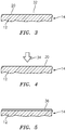
- FIG. 3 shows a schematic representation of a surface 20 of a substrate 12 which has organic contaminants 32 on surface 20.
- contaminants can typically be hydrophobic.
- typical organic contaminants encountered during preparation of ceramic matrix component articles are absorbed hydrocarbons, oils from human handling (such as finger prints), lubricants from machining, residual hydrocarbon based contaminants from the process of making the substrate (for example through chemical vapor infiltration (CVI) or preceramic polymer pyrolosis).
- CVI chemical vapor infiltration
- preceramic polymer pyrolosis residual hydrocarbon based contaminants from the process of making the substrate.
- an environmental barrier coating 10 or layer 18 Figs. 1, 2
- one application method is application as an aqueous slurry.
- Such processes produce good quality coatings when there is good adhesion of the slurry with the surface.
- hydrophobic contaminants on the surface can interfere with such adhesion.
- the surface of FIG. 4 can be treated, for example with a plasma treatment 34, to remove the organic contaminants 32 (already removed in Fig. 4 ) and produce a surface 20 which is more wettable to aqueous slurry-based materials.
- FIG. 4 schematically illustrates a plasma treatment step 34 to remove organic contaminants 32.
- This plasma treatment step can be carried out using any plasma bath, jet, spray or other treatment method which results in removal of organic contaminants to adjust wettability of the surface to be coated.
- the part or parts having a substrate to be coated can be placed in a plasma chamber, and a vacuum can then be drawn in the chamber.
- a gas can be backfilled into the chamber at a partial pressure. Composition of the gas can be changed as desired to change the effect on the surface.
- plasma is then generated, for example using RF excitation, to expose the desired surface to plasma and thereby alter the surface by removing organic contaminants.
- HF gas may remove oxides on the substrate and provide a fresh surface
- oxidizing gas may remove contaminants and may create a very controlled oxidized layer that increases wetting.
- Power used to create the plasma can also be varied to control the degree of surface modification.
- Low-pressure (high vacuum) conditions enhance the plasma etch rates and the use of vacuum better than 10 -2 -10 -6 atmospheres (1.0 kPa - 0.1 Pa) is desirable.
- the plasma is achieved in the system by applying a strong radio frequency electromagnetic field to the chamber.
- wettability of surface 20 is now sufficiently adjusted that an aqueous slurry-based coating can be applied to surface 20, resulting in an even and well wetted layer 36 of aqueous slurry-based coating materials on surface 20 such that subsequent curing and finishing steps result in an environmental barrier coating having high adhesion to the underlying surface as desired.
- the treatment step can be conducted to produce a hydrophilic surface, which of course enhances wetting with an aqueous-slurry based coating composition. It is well-suited to the overall process to conduct the treatment step to produce a surface which has a contact angle with water and/or with an aqueous-slurry based coating composition or fluid of less than 40 degrees.
- the disclosed method can be used to adjust the wettability of a surface to be coated with aqueous slurry-based materials such that the aqueous slurry-based materials fully wet the surface. This promotes strong adhesion of the thus-applied coating, and enables the capability of the environmental barrier coating system to endure higher thermal gradients, retain larger coating thickness, longer coating life, and higher resistance to spallation.
Landscapes
- Engineering & Computer Science (AREA)
- Chemical & Material Sciences (AREA)
- Ceramic Engineering (AREA)
- Materials Engineering (AREA)
- Structural Engineering (AREA)
- Organic Chemistry (AREA)
- Mechanical Engineering (AREA)
- General Engineering & Computer Science (AREA)
- Inorganic Chemistry (AREA)
- Plasma & Fusion (AREA)
- Physics & Mathematics (AREA)
- Application Of Or Painting With Fluid Materials (AREA)
- Turbine Rotor Nozzle Sealing (AREA)
Abstract
Description
- The disclosure relates to environmental barrier coatings for articles or substrates containing silicon. The environmental barrier coating (EBC) functions as a protective environmental barrier coating and inhibits the formation of gaseous species of Si, particularly Si(OH)x when the article is exposed to a high temperature, aqueous (water and/or steam) environment.
- Ceramic materials containing silicon and metal alloys containing silicon have been proposed for structures used in high temperature applications such as, for example, gas turbine engines, heat exchangers, internal combustion engines, and the like. A particularly useful application for these materials is in gas turbine engines which operate at high temperatures in aqueous environments. The light weight of the ceramic materials makes them desirable for such uses.
- It has been found that these silicon containing substrates can recede and lose mass as a result of formation of volatile Si species, particularly Si(OH)x and SiO when exposed to high temperature, aqueous environments.
- It is believed that the process involves oxidation of the silicon carbide to form silica on the surface of the silicon carbide followed by reaction of the silica with steam to form volatile species of silicon such as Si(OH)x. Naturally it would be highly desirable to provide an environmental barrier coating for silicon containing substrates which would inhibit the formation of volatile silicon species, Si(OH)x and SiO, and thereby reduce recession and mass loss.
- It would also be highly desirable to apply such environmental barrier coatings in a way which results in good bonding of the coating to the substrate.
- In accordance with the present disclosure, there is provided a method for coating a ceramic matrix composite substrate with an environmental barrier coating, comprising the steps of treating a surface of a ceramic matrix composite substrate to adjust wettability of the surface; and applying an aqueous slurry-based environmental barrier coating to the surface.
- In one non-limiting configuration, the substrate is at least one of a turbine vane or a turbine blade.
- In another non-limiting configuration, the surface has organic contaminants, and the treating step removes the organic contaminants.
- In a further non-limiting configuration, the organic contaminants comprise absorbed hydrocarbons, surface contaminants from handling, machining and packaging, and residual contaminants from the manufacturing process.
- In a still further non-limiting configuration, the treating step comprises changing the oxidative state of the surface to adjust wettability of the surface.
- In still another non-limiting configuration, the treating step is a plasma treating step.
- In another non-limiting configuration, the plasma treating step comprises placing the substrate in a chamber, evacuating the chamber, introducing process gas to the chamber, and generating plasma within the chamber.
- In another non-limiting embodiment, the process gas is selected from the group consisting of fluorine gas, Sulphur hexafluoride, water vapor, hydrogen, chlorine gas, hydrochloric acid, argon, iodine monobromide (IBr), iodine monochloride (ICl) and combinations thereof.
- In a further non-limiting configuration, the aqueous slurry-based coating comprises a mixture of water, binder, and oxidation protection phase.
- In a still further non-limiting configuration, the treating step produces a surface that is hydrophilic.
- In still another non-limiting configuration, the treating step produces a surface having a contact angle of less than 40 degrees with the aqueous slurry-based environmental barrier coating.
- In another non-limiting configuration, the applying step is selected from the group consisting of spraying, dipping, electrophoretic application, painting and combinations thereof.
- In a further non-limiting configuration, the method further comprises the step of applying environmental barrier coating materials to the surface as an aqueous-slurry, and curing the aqueous-slurry on the surface to produce the environmental barrier coating.
- In another alternative configuration, the method further comprises applying a protective layer over the environmental barrier coating.
- Other details of the coating method are set forth in the following detailed description and the accompanying drawings wherein like reference numerals depict like elements.
-
-
FIG. 1 is a cross section of an exemplary coating on a substrate containing silicon according to the disclosure; -
FIG. 2 is a cross section of an exemplary coating on a substrate containing silicon according to the disclosure; and -
FIGS. 3-5 schematically illustrate steps in a method for applying an EBC as an aqueous slurry. - The disclosure relates to a method for controlled wetting during application of an aqueous slurry-based environmental barrier coating (EBC) to a silicon-containing substrate such as a ceramic matrix composite (CMC) substrate. The controlled wetting includes plasma treatment to remove organic surface contaminants from the surface of the substrate to be treated. Such contaminants can be hydrophobic, creating a high surface tension with the aqueous coating materials, and preventing wetting, which results in potentially low adherence of the resulting EBC.
- An aqueous slurry as referred to herein generally has, as main constituent, an aqueous suspension of nanometer sized colloidal silica particles. This acts as an inorganic binder and holds other constituents of the slurry in place including but not limited to more water, gettering particles, and self-healing phase. Modifiers can be added including dispersants and surfactants.
- Referring to
FIG. 1 , there is illustrated anenvironmental barrier coating 10 formed over asubstrate 12 of anarticle 14.Coating 10 is configured to inhibit the formation of gaseous species of silicon when thearticle 14 is exposed to a high temperature, aqueous environment. Thesubstrate 12 can be associated witharticles 14 such as a turbine vane or a turbine blade, and/or any other component or components of a gas turbine engine, such as components in the hot section of the gas turbine engine, including rotating components and portions of combustors, and the like. - The
substrate 12 can be constructed from materials containing silicon and can be a ceramic matrix composite material, a monolithic ceramic, a silicon-based or silicon containing ceramic substrate or a silicon containing metal alloy. In an exemplary embodiment, thesubstrate 12 can be silicon containing ceramic material such as, for example, silicon carbide, silicon nitride, silicon oxy-nitride and silicon aluminum oxy-nitride, alkaline earth or rare earth silicate glasses or glass ceramics and combinations thereof. Examples can include barium strontium aluminosilicate, strontium aluminosilicate, lithium aluminosilicate, aluminosilicate, mullite, yttrium silicate, ytterbium silicate, and the like. In accordance with a particular embodiment, the silicon containing ceramic substrate comprises a silicon containing matrix with reinforcingmaterials 16 such as fibers, particles and the like and, more particularly, a silicon based matrix which is fiber-reinforced. Particularly suitable ceramic substrates are a silicon carbide coated silicon carbide fiber-reinforced silicon carbide particle and silicon matrix, a carbon fiber-reinforced silicon carbide matrix and a silicon carbide fiber-reinforced silicon nitride matrix. Particularly useful silicon-metal alloys for use as substrates for thearticle 14 can include molybdenum-silicon alloys, niobium-silicon alloys, iron-silicon alloys, aluminum-silicon alloys, and silicon alloys with one or more of zirconium, hafnium, titanium, chromium, tungsten, boron, platinum and tantalum. - Referring also to
FIG. 2 , anenvironmental barrier layer 18 can be applied to thesubstrate 14 on asurface 20. Aprotective layer 22 can be applied on theenvironmental barrier layer 18. Theprotective layer 22 can be configured to resist recession of the Si-containing volatile species when exposed to water vapor or steam. In an exemplary embodiment, theprotective layer 22 can include binary or multicomponent oxides such as HfO2, ZrO2, or Gd2Hf2O7, Gd2Zr2O7, and refractory metal oxides. In other exemplary embodiments, theprotective layer 22 can include silicates with lower SiO2 activities. In another exemplary embodiment theprotective layer 22 can include rare earth (RE) monosilicates, disilicates and alkaline earth (AE) aluminosilicates, silicates of Hafnium and zirconium. - The present disclosure is directed to enhancing adhesion of aqueous slurry-based coatings on
surface 20 ofsubstrate 12. Such slurries can be applied by spraying, dipping, electrophoretic application, painting, and the like, and combinations thereof. In one non-limiting configuration, the resultingenvironmental barrier layer 18 can include anoxide matrix 24 and anoxidant getter phase 26 interspersed throughout theoxide matrix 24. Theoxide matrix 24 can include a multi-phase mixture, such as a SiO2 rich phase and a self-healing phase 28 that can include a glass phase. In an exemplary embodiment, the composition of theoxide matrix 24 dictates the mole fraction of the glass and the SiO2. The self-healing phase 28 can include a material having properties that are in thermodynamic equilibrium with SiO2 during operation at predetermined temperatures. The self-healing phase 28 comprises a material having properties including the ability to flow intocracks 30 formed in thematrix 24 during operation at those predetermined temperatures. The self-healing phase 28 can be sufficiently fluid at high temperatures to flow into thecracks 30 in thecoating 10, which imparts a self-healing functionality. The present disclosure is directed to aqueous slurry-based EBC application, and so the above composition or other compositions could be advantageously applied in this manner. - The aqueous-slurry based environmental barrier coating composition can be a mixture of water, binder, and oxidation protection phase, as would be known to a person having ordinary skill in the art, and can be as set forth above. These components can be provided in a broad range of ratios relative to each other, depending upon desired properties of the resultant coating.
- The
environmental barrier layer 18 can be applied tosubstrate 12 at a thickness of greater than or equal to about 0.5 mils (0.0005 inch, 0.0127 mm), preferably between about 3 and about 30 mils (0.0762 to 0.762 mm) and more preferably between about 3 and about 5 mils (0.0762 to 0.127 mm). - It is advantageous to apply the
environmental barrier layer 18 to thesurface 20 of thesubstrate 14 after thesurface 20 has been treated and prepared to enhance wettability of the surface with an aqueous-slurry based fluid. Sincesurface 20 can have organic contaminants which can be hydrophobic, these contaminants can be problematic for a number of reasons, some related to the aqueous materials used in the method for application of theenvironmental barrier layer 18. The organic contaminants can be removed from thesurface 20 via techniques such as plasma treatment. In order to obtain good adhesion of theenvironmental barrier layer 18 to thesurface 20 it can be advantageous to enhance the properties of thesurface 20. - In one aspect of the disclosure, the environmental barrier coating is applied in the form of an aqueous slurry. Application as a slurry allows relatively simple and uniform application of the EBC as desired, followed by curing into the final coating. However, good adherence to the surface of the substrate is important in providing a good bond of the coating to the substrate. Thus, treating the surface to enhance wettability can greatly improve overall adhesion of the resultant coating. Without such a treatment, the surface can be hydrophobic, resulting in poor dispersion or wetting of the aqueous slurry over the substrate to be coated, and poor quality coating.
-
FIG. 3 shows a schematic representation of asurface 20 of asubstrate 12 which hasorganic contaminants 32 onsurface 20. As set forth above, such contaminants can typically be hydrophobic. Non-limiting examples of typical organic contaminants encountered during preparation of ceramic matrix component articles are absorbed hydrocarbons, oils from human handling (such as finger prints), lubricants from machining, residual hydrocarbon based contaminants from the process of making the substrate (for example through chemical vapor infiltration (CVI) or preceramic polymer pyrolosis). When such an article is to be coated with anenvironmental barrier coating 10 or layer 18 (Figs. 1, 2 ), one application method is application as an aqueous slurry. Such processes produce good quality coatings when there is good adhesion of the slurry with the surface. Of course, hydrophobic contaminants on the surface can interfere with such adhesion. Thus, it is desirable to treat the surface to be coated to adjust the wettability of the surface to aqueous based materials. - In one aspect of such adjustment of wettability, the surface of
FIG. 4 can be treated, for example with aplasma treatment 34, to remove the organic contaminants 32 (already removed inFig. 4 ) and produce asurface 20 which is more wettable to aqueous slurry-based materials. -
FIG. 4 schematically illustrates aplasma treatment step 34 to removeorganic contaminants 32. This plasma treatment step can be carried out using any plasma bath, jet, spray or other treatment method which results in removal of organic contaminants to adjust wettability of the surface to be coated. In a typical plasma treatment process, the part or parts having a substrate to be coated can be placed in a plasma chamber, and a vacuum can then be drawn in the chamber. A gas can be backfilled into the chamber at a partial pressure. Composition of the gas can be changed as desired to change the effect on the surface. In addition, other methods can be used to introduce reactive gases into the plasma chamber including but not limited to the use of at least one of fluorine gas, Sulphur hexafluoride, water vapor, hydrogen, chlorine gas, hydrochloric acid, argon, iodine monobromide, iodine monochloride and the like. Plasma is then generated, for example using RF excitation, to expose the desired surface to plasma and thereby alter the surface by removing organic contaminants. - Chemical species of the gas can create a significant effect. For example, on a silicon carbide substrate, HF gas may remove oxides on the substrate and provide a fresh surface, oxidizing gas may remove contaminants and may create a very controlled oxidized layer that increases wetting. Power used to create the plasma can also be varied to control the degree of surface modification. Low-pressure (high vacuum) conditions enhance the plasma etch rates and the use of vacuum better than 10-2-10-6 atmospheres (1.0 kPa - 0.1 Pa) is desirable. In one configuration, the plasma is achieved in the system by applying a strong radio frequency electromagnetic field to the chamber.
- After
treatment step 34, wettability ofsurface 20 is now sufficiently adjusted that an aqueous slurry-based coating can be applied tosurface 20, resulting in an even and well wettedlayer 36 of aqueous slurry-based coating materials onsurface 20 such that subsequent curing and finishing steps result in an environmental barrier coating having high adhesion to the underlying surface as desired. The treatment step can be conducted to produce a hydrophilic surface, which of course enhances wetting with an aqueous-slurry based coating composition. It is well-suited to the overall process to conduct the treatment step to produce a surface which has a contact angle with water and/or with an aqueous-slurry based coating composition or fluid of less than 40 degrees. - Along with the disclosed process for removing organic contaminants using plasma and other treatment, it is also within the scope of this disclosure to alter the surface by changing the oxidative state of the surface, which can also alter the wettability of the surface. The disclosed method can be used to adjust the wettability of a surface to be coated with aqueous slurry-based materials such that the aqueous slurry-based materials fully wet the surface. This promotes strong adhesion of the thus-applied coating, and enables the capability of the environmental barrier coating system to endure higher thermal gradients, retain larger coating thickness, longer coating life, and higher resistance to spallation.
- There has been provided a method of adjusting wettability of a surface for an environmental barrier coating. While the coating has been described in the context of specific embodiments thereof, other unforeseen alternatives, modifications, and variations may become apparent to those skilled in the art having read the foregoing description. Accordingly, it is intended to embrace those alternatives, modifications, and variations which fall within the broad scope of the appended claims.
Claims (14)
- A method for coating a ceramic matrix composite substrate (12) with an environmental barrier coating (10), comprising the steps of:treating a surface (20) of a ceramic matrix composite substrate (12) to adjust wettability of the surface (20); andapplying an aqueous slurry-based environmental barrier coating (18) to the surface (20).
- The method of claim 1, wherein the substrate (12) is at least one of a turbine vane or a turbine blade.
- The method of claim 1 or 2, wherein the surface (20) has organic contaminants (32), and wherein the treating step removes the organic contaminants (32).
- The method of claim 3, wherein the organic contaminants (32) comprise absorbed hydrocarbons, surface contaminants from handling, machining and packaging, and residual contaminants from the manufacturing process.
- The method of any preceding claim, wherein the treating step comprises changing the oxidative state of the surface (20) to adjust wettability of the surface (20).
- The method of any preceding claim, wherein the treating step is a plasma treating step (34).
- The method of claim 6, wherein the plasma treating step (34) comprises placing the substrate (12) in a chamber, evacuating the chamber, introducing process gas to the chamber, and generating plasma within the chamber.
- The method of claim 7, wherein the process gas is selected from the group consisting of fluorine gas, Sulphur hexafluoride, water vapor, hydrogen, chlorine gas, hydrochloric acid, argon, IBr, ICl and combinations thereof.
- The method of any preceding claim, wherein the aqueous slurry-based environmental barrier coating (18) comprises a mixture of water, binder, and oxidation protection phase.
- The method of any preceding claim, wherein the treating step produces a surface (20) that is hydrophilic.
- The method of any preceding claim, wherein the treating step produces a surface (20) having a contact angle of less than 40 degrees with the aqueous slurry-based environmental barrier coating (18).
- The method of any preceding claim, wherein the applying step is selected from the group consisting of spraying, dipping, electrophoretic application, painting and combinations thereof.
- The method of any preceding claim, further comprising the step of applying environmental barrier coating materials to the surface (20) as an aqueous-slurry, and curing the aqueous-slurry on the surface (20) to produce the environmental barrier coating (18) .
- The method of any preceding claim, further comprising applying a protective layer (22) over the environmental barrier coating (18).
Applications Claiming Priority (1)
| Application Number | Priority Date | Filing Date | Title |
|---|---|---|---|
| US15/998,733 US20200055083A1 (en) | 2018-08-16 | 2018-08-16 | Surface treatment for aqueous slurry-based environmental barrier coating |
Publications (2)
| Publication Number | Publication Date |
|---|---|
| EP3611148A1 true EP3611148A1 (en) | 2020-02-19 |
| EP3611148B1 EP3611148B1 (en) | 2021-05-26 |
Family
ID=67659126
Family Applications (1)
| Application Number | Title | Priority Date | Filing Date |
|---|---|---|---|
| EP19192149.3A Active EP3611148B1 (en) | 2018-08-16 | 2019-08-16 | Surface treatment for aqueous slurry-based environmental barrier coating |
Country Status (2)
| Country | Link |
|---|---|
| US (2) | US20200055083A1 (en) |
| EP (1) | EP3611148B1 (en) |
Cited By (1)
| Publication number | Priority date | Publication date | Assignee | Title |
|---|---|---|---|---|
| WO2021175879A1 (en) * | 2020-03-03 | 2021-09-10 | Lufthansa Technik Ag | Cleaning method for ceramic fiber composite materials |
Families Citing this family (1)
| Publication number | Priority date | Publication date | Assignee | Title |
|---|---|---|---|---|
| US12371389B2 (en) * | 2022-02-04 | 2025-07-29 | Rtx Corporation | Adaptive surface texturing for ceramic matrix composites |
Citations (2)
| Publication number | Priority date | Publication date | Assignee | Title |
|---|---|---|---|---|
| US20030054131A1 (en) * | 2001-09-19 | 2003-03-20 | Akio Ooshima | Carrier member made of a UV resistant fiber-reinforced composite material and process for producing thereof |
| US20090297718A1 (en) * | 2008-05-29 | 2009-12-03 | General Electric Company | Methods of fabricating environmental barrier coatings for silicon based substrates |
Family Cites Families (8)
| Publication number | Priority date | Publication date | Assignee | Title |
|---|---|---|---|---|
| US5389195A (en) * | 1991-03-07 | 1995-02-14 | Minnesota Mining And Manufacturing Company | Surface modification by accelerated plasma or ions |
| GB9204791D0 (en) * | 1992-03-05 | 1992-04-22 | Rolls Royce Plc | A coated article |
| US5965629A (en) * | 1996-04-19 | 1999-10-12 | Korea Institute Of Science And Technology | Process for modifying surfaces of materials, and materials having surfaces modified thereby |
| US8697195B2 (en) * | 2006-01-30 | 2014-04-15 | General Electric Company | Method for forming a protective coating with enhanced adhesion between layers |
| US8124252B2 (en) | 2008-11-25 | 2012-02-28 | Rolls-Royce Corporation | Abradable layer including a rare earth silicate |
| US9428650B2 (en) | 2012-12-11 | 2016-08-30 | General Electric Company | Environmental barrier coatings and methods therefor |
| CN105814007B (en) * | 2013-12-12 | 2019-05-07 | 通用电气公司 | Method for depositing abradable coatings in polymer gel form |
| US20170305797A1 (en) * | 2016-04-22 | 2017-10-26 | Rolls-Royce Corporation | Slurry-based reaction bonded environmental barrier coatings |
-
2018
- 2018-08-16 US US15/998,733 patent/US20200055083A1/en not_active Abandoned
-
2019
- 2019-08-16 EP EP19192149.3A patent/EP3611148B1/en active Active
-
2023
- 2023-03-13 US US18/120,686 patent/US12246343B2/en active Active
Patent Citations (2)
| Publication number | Priority date | Publication date | Assignee | Title |
|---|---|---|---|---|
| US20030054131A1 (en) * | 2001-09-19 | 2003-03-20 | Akio Ooshima | Carrier member made of a UV resistant fiber-reinforced composite material and process for producing thereof |
| US20090297718A1 (en) * | 2008-05-29 | 2009-12-03 | General Electric Company | Methods of fabricating environmental barrier coatings for silicon based substrates |
Cited By (1)
| Publication number | Priority date | Publication date | Assignee | Title |
|---|---|---|---|---|
| WO2021175879A1 (en) * | 2020-03-03 | 2021-09-10 | Lufthansa Technik Ag | Cleaning method for ceramic fiber composite materials |
Also Published As
| Publication number | Publication date |
|---|---|
| US12246343B2 (en) | 2025-03-11 |
| US20200055083A1 (en) | 2020-02-20 |
| US20230211374A1 (en) | 2023-07-06 |
| EP3611148B1 (en) | 2021-05-26 |
Similar Documents
| Publication | Publication Date | Title |
|---|---|---|
| KR100390291B1 (en) | Silicon based substrate with yttrium silicate environmental/thermal barrier layer | |
| US7910172B2 (en) | Method for fabricating a component having an environmental barrier coating | |
| KR100390290B1 (en) | Article comprising silicon based substrate with calcium aluminosilicate environmental/thermal barrier layer | |
| KR100390289B1 (en) | Article comprising silicon based substrate with environmental/thermal barrier layer | |
| JP6771861B2 (en) | Compositions and Methods for Spraying Airtight Rare Earth Environmentally Resistant Films | |
| US11131026B2 (en) | Sintered-bonded high temperature coatings for ceramic turbomachine components | |
| US20090297718A1 (en) | Methods of fabricating environmental barrier coatings for silicon based substrates | |
| US10934220B2 (en) | Chemical and topological surface modification to enhance coating adhesion and compatibility | |
| US12246343B2 (en) | Surface treatment for aqueous slurry-based environmental barrier coating | |
| EP1666626A1 (en) | Protective coatings | |
| JP2007084421A (en) | Article equipped with barrier layer and method of forming coating | |
| CN107129320B (en) | Environmental barrier coating and preparation method thereof | |
| CN110382446A (en) | The method based on slurry for being used to form adhesive coatings and the product by this method formation | |
| US9540497B2 (en) | Silicon-based repair methods and composition | |
| JP2016512810A (en) | Slurry coating repair | |
| JP2007229704A (en) | High-density protective coating, method for manufacturing the same and coated article | |
| EP3604257B1 (en) | Article comprising a fiber-reinforced self-healing bond coat | |
| US11905222B2 (en) | Environmental barrier coating for enhanced resistance to attack by molten silicate deposits |
Legal Events
| Date | Code | Title | Description |
|---|---|---|---|
| PUAI | Public reference made under article 153(3) epc to a published international application that has entered the european phase |
Free format text: ORIGINAL CODE: 0009012 |
|
| STAA | Information on the status of an ep patent application or granted ep patent |
Free format text: STATUS: THE APPLICATION HAS BEEN PUBLISHED |
|
| AK | Designated contracting states |
Kind code of ref document: A1 Designated state(s): AL AT BE BG CH CY CZ DE DK EE ES FI FR GB GR HR HU IE IS IT LI LT LU LV MC MK MT NL NO PL PT RO RS SE SI SK SM TR |
|
| AX | Request for extension of the european patent |
Extension state: BA ME |
|
| STAA | Information on the status of an ep patent application or granted ep patent |
Free format text: STATUS: REQUEST FOR EXAMINATION WAS MADE |
|
| 17P | Request for examination filed |
Effective date: 20200819 |
|
| RBV | Designated contracting states (corrected) |
Designated state(s): AL AT BE BG CH CY CZ DE DK EE ES FI FR GB GR HR HU IE IS IT LI LT LU LV MC MK MT NL NO PL PT RO RS SE SI SK SM TR |
|
| GRAP | Despatch of communication of intention to grant a patent |
Free format text: ORIGINAL CODE: EPIDOSNIGR1 |
|
| STAA | Information on the status of an ep patent application or granted ep patent |
Free format text: STATUS: GRANT OF PATENT IS INTENDED |
|
| RIC1 | Information provided on ipc code assigned before grant |
Ipc: C04B 41/85 20060101AFI20201030BHEP Ipc: F01D 5/28 20060101ALI20201030BHEP |
|
| INTG | Intention to grant announced |
Effective date: 20201209 |
|
| RAP1 | Party data changed (applicant data changed or rights of an application transferred) |
Owner name: RAYTHEON TECHNOLOGIES CORPORATION |
|
| GRAS | Grant fee paid |
Free format text: ORIGINAL CODE: EPIDOSNIGR3 |
|
| GRAA | (expected) grant |
Free format text: ORIGINAL CODE: 0009210 |
|
| STAA | Information on the status of an ep patent application or granted ep patent |
Free format text: STATUS: THE PATENT HAS BEEN GRANTED |
|
| AK | Designated contracting states |
Kind code of ref document: B1 Designated state(s): AL AT BE BG CH CY CZ DE DK EE ES FI FR GB GR HR HU IE IS IT LI LT LU LV MC MK MT NL NO PL PT RO RS SE SI SK SM TR |
|
| REG | Reference to a national code |
Ref country code: GB Ref legal event code: FG4D |
|
| REG | Reference to a national code |
Ref country code: CH Ref legal event code: EP |
|
| REG | Reference to a national code |
Ref country code: AT Ref legal event code: REF Ref document number: 1396096 Country of ref document: AT Kind code of ref document: T Effective date: 20210615 |
|
| REG | Reference to a national code |
Ref country code: DE Ref legal event code: R096 Ref document number: 602019004857 Country of ref document: DE |
|
| REG | Reference to a national code |
Ref country code: IE Ref legal event code: FG4D |
|
| REG | Reference to a national code |
Ref country code: LT Ref legal event code: MG9D |
|
| REG | Reference to a national code |
Ref country code: AT Ref legal event code: MK05 Ref document number: 1396096 Country of ref document: AT Kind code of ref document: T Effective date: 20210526 |
|
| PG25 | Lapsed in a contracting state [announced via postgrant information from national office to epo] |
Ref country code: AT Free format text: LAPSE BECAUSE OF FAILURE TO SUBMIT A TRANSLATION OF THE DESCRIPTION OR TO PAY THE FEE WITHIN THE PRESCRIBED TIME-LIMIT Effective date: 20210526 Ref country code: BG Free format text: LAPSE BECAUSE OF FAILURE TO SUBMIT A TRANSLATION OF THE DESCRIPTION OR TO PAY THE FEE WITHIN THE PRESCRIBED TIME-LIMIT Effective date: 20210826 Ref country code: FI Free format text: LAPSE BECAUSE OF FAILURE TO SUBMIT A TRANSLATION OF THE DESCRIPTION OR TO PAY THE FEE WITHIN THE PRESCRIBED TIME-LIMIT Effective date: 20210526 Ref country code: LT Free format text: LAPSE BECAUSE OF FAILURE TO SUBMIT A TRANSLATION OF THE DESCRIPTION OR TO PAY THE FEE WITHIN THE PRESCRIBED TIME-LIMIT Effective date: 20210526 Ref country code: HR Free format text: LAPSE BECAUSE OF FAILURE TO SUBMIT A TRANSLATION OF THE DESCRIPTION OR TO PAY THE FEE WITHIN THE PRESCRIBED TIME-LIMIT Effective date: 20210526 |
|
| REG | Reference to a national code |
Ref country code: NL Ref legal event code: MP Effective date: 20210526 |
|
| PG25 | Lapsed in a contracting state [announced via postgrant information from national office to epo] |
Ref country code: GR Free format text: LAPSE BECAUSE OF FAILURE TO SUBMIT A TRANSLATION OF THE DESCRIPTION OR TO PAY THE FEE WITHIN THE PRESCRIBED TIME-LIMIT Effective date: 20210827 Ref country code: IS Free format text: LAPSE BECAUSE OF FAILURE TO SUBMIT A TRANSLATION OF THE DESCRIPTION OR TO PAY THE FEE WITHIN THE PRESCRIBED TIME-LIMIT Effective date: 20210926 Ref country code: LV Free format text: LAPSE BECAUSE OF FAILURE TO SUBMIT A TRANSLATION OF THE DESCRIPTION OR TO PAY THE FEE WITHIN THE PRESCRIBED TIME-LIMIT Effective date: 20210526 Ref country code: NO Free format text: LAPSE BECAUSE OF FAILURE TO SUBMIT A TRANSLATION OF THE DESCRIPTION OR TO PAY THE FEE WITHIN THE PRESCRIBED TIME-LIMIT Effective date: 20210826 Ref country code: PL Free format text: LAPSE BECAUSE OF FAILURE TO SUBMIT A TRANSLATION OF THE DESCRIPTION OR TO PAY THE FEE WITHIN THE PRESCRIBED TIME-LIMIT Effective date: 20210526 Ref country code: PT Free format text: LAPSE BECAUSE OF FAILURE TO SUBMIT A TRANSLATION OF THE DESCRIPTION OR TO PAY THE FEE WITHIN THE PRESCRIBED TIME-LIMIT Effective date: 20210927 Ref country code: RS Free format text: LAPSE BECAUSE OF FAILURE TO SUBMIT A TRANSLATION OF THE DESCRIPTION OR TO PAY THE FEE WITHIN THE PRESCRIBED TIME-LIMIT Effective date: 20210526 Ref country code: SE Free format text: LAPSE BECAUSE OF FAILURE TO SUBMIT A TRANSLATION OF THE DESCRIPTION OR TO PAY THE FEE WITHIN THE PRESCRIBED TIME-LIMIT Effective date: 20210526 |
|
| PG25 | Lapsed in a contracting state [announced via postgrant information from national office to epo] |
Ref country code: NL Free format text: LAPSE BECAUSE OF FAILURE TO SUBMIT A TRANSLATION OF THE DESCRIPTION OR TO PAY THE FEE WITHIN THE PRESCRIBED TIME-LIMIT Effective date: 20210526 |
|
| PG25 | Lapsed in a contracting state [announced via postgrant information from national office to epo] |
Ref country code: SK Free format text: LAPSE BECAUSE OF FAILURE TO SUBMIT A TRANSLATION OF THE DESCRIPTION OR TO PAY THE FEE WITHIN THE PRESCRIBED TIME-LIMIT Effective date: 20210526 Ref country code: EE Free format text: LAPSE BECAUSE OF FAILURE TO SUBMIT A TRANSLATION OF THE DESCRIPTION OR TO PAY THE FEE WITHIN THE PRESCRIBED TIME-LIMIT Effective date: 20210526 Ref country code: ES Free format text: LAPSE BECAUSE OF FAILURE TO SUBMIT A TRANSLATION OF THE DESCRIPTION OR TO PAY THE FEE WITHIN THE PRESCRIBED TIME-LIMIT Effective date: 20210526 Ref country code: RO Free format text: LAPSE BECAUSE OF FAILURE TO SUBMIT A TRANSLATION OF THE DESCRIPTION OR TO PAY THE FEE WITHIN THE PRESCRIBED TIME-LIMIT Effective date: 20210526 Ref country code: SM Free format text: LAPSE BECAUSE OF FAILURE TO SUBMIT A TRANSLATION OF THE DESCRIPTION OR TO PAY THE FEE WITHIN THE PRESCRIBED TIME-LIMIT Effective date: 20210526 Ref country code: DK Free format text: LAPSE BECAUSE OF FAILURE TO SUBMIT A TRANSLATION OF THE DESCRIPTION OR TO PAY THE FEE WITHIN THE PRESCRIBED TIME-LIMIT Effective date: 20210526 Ref country code: CZ Free format text: LAPSE BECAUSE OF FAILURE TO SUBMIT A TRANSLATION OF THE DESCRIPTION OR TO PAY THE FEE WITHIN THE PRESCRIBED TIME-LIMIT Effective date: 20210526 |
|
| REG | Reference to a national code |
Ref country code: DE Ref legal event code: R097 Ref document number: 602019004857 Country of ref document: DE |
|
| PLBE | No opposition filed within time limit |
Free format text: ORIGINAL CODE: 0009261 |
|
| STAA | Information on the status of an ep patent application or granted ep patent |
Free format text: STATUS: NO OPPOSITION FILED WITHIN TIME LIMIT |
|
| PG25 | Lapsed in a contracting state [announced via postgrant information from national office to epo] |
Ref country code: MC Free format text: LAPSE BECAUSE OF FAILURE TO SUBMIT A TRANSLATION OF THE DESCRIPTION OR TO PAY THE FEE WITHIN THE PRESCRIBED TIME-LIMIT Effective date: 20210526 |
|
| REG | Reference to a national code |
Ref country code: BE Ref legal event code: MM Effective date: 20210831 |
|
| 26N | No opposition filed |
Effective date: 20220301 |
|
| PG25 | Lapsed in a contracting state [announced via postgrant information from national office to epo] |
Ref country code: IS Free format text: LAPSE BECAUSE OF FAILURE TO SUBMIT A TRANSLATION OF THE DESCRIPTION OR TO PAY THE FEE WITHIN THE PRESCRIBED TIME-LIMIT Effective date: 20210926 Ref country code: LU Free format text: LAPSE BECAUSE OF NON-PAYMENT OF DUE FEES Effective date: 20210816 Ref country code: AL Free format text: LAPSE BECAUSE OF FAILURE TO SUBMIT A TRANSLATION OF THE DESCRIPTION OR TO PAY THE FEE WITHIN THE PRESCRIBED TIME-LIMIT Effective date: 20210526 |
|
| PG25 | Lapsed in a contracting state [announced via postgrant information from national office to epo] |
Ref country code: IT Free format text: LAPSE BECAUSE OF FAILURE TO SUBMIT A TRANSLATION OF THE DESCRIPTION OR TO PAY THE FEE WITHIN THE PRESCRIBED TIME-LIMIT Effective date: 20210526 Ref country code: IE Free format text: LAPSE BECAUSE OF NON-PAYMENT OF DUE FEES Effective date: 20210816 Ref country code: BE Free format text: LAPSE BECAUSE OF NON-PAYMENT OF DUE FEES Effective date: 20210831 |
|
| REG | Reference to a national code |
Ref country code: CH Ref legal event code: PL |
|
| PG25 | Lapsed in a contracting state [announced via postgrant information from national office to epo] |
Ref country code: LI Free format text: LAPSE BECAUSE OF NON-PAYMENT OF DUE FEES Effective date: 20220831 Ref country code: CH Free format text: LAPSE BECAUSE OF NON-PAYMENT OF DUE FEES Effective date: 20220831 |
|
| P01 | Opt-out of the competence of the unified patent court (upc) registered |
Effective date: 20230521 |
|
| PG25 | Lapsed in a contracting state [announced via postgrant information from national office to epo] |
Ref country code: CY Free format text: LAPSE BECAUSE OF FAILURE TO SUBMIT A TRANSLATION OF THE DESCRIPTION OR TO PAY THE FEE WITHIN THE PRESCRIBED TIME-LIMIT Effective date: 20210526 |
|
| PG25 | Lapsed in a contracting state [announced via postgrant information from national office to epo] |
Ref country code: HU Free format text: LAPSE BECAUSE OF FAILURE TO SUBMIT A TRANSLATION OF THE DESCRIPTION OR TO PAY THE FEE WITHIN THE PRESCRIBED TIME-LIMIT; INVALID AB INITIO Effective date: 20190816 |
|
| PG25 | Lapsed in a contracting state [announced via postgrant information from national office to epo] |
Ref country code: MK Free format text: LAPSE BECAUSE OF FAILURE TO SUBMIT A TRANSLATION OF THE DESCRIPTION OR TO PAY THE FEE WITHIN THE PRESCRIBED TIME-LIMIT Effective date: 20210526 |
|
| PG25 | Lapsed in a contracting state [announced via postgrant information from national office to epo] |
Ref country code: MT Free format text: LAPSE BECAUSE OF FAILURE TO SUBMIT A TRANSLATION OF THE DESCRIPTION OR TO PAY THE FEE WITHIN THE PRESCRIBED TIME-LIMIT Effective date: 20210526 |
|
| REG | Reference to a national code |
Ref country code: DE Ref legal event code: R081 Ref document number: 602019004857 Country of ref document: DE Owner name: RTX CORPORATION (N.D.GES.D. STAATES DELAWARE),, US Free format text: FORMER OWNER: RAYTHEON TECHNOLOGIES CORPORATION, FARMINGTON, CT, US |
|
| PGFP | Annual fee paid to national office [announced via postgrant information from national office to epo] |
Ref country code: DE Payment date: 20250724 Year of fee payment: 7 |
|
| PGFP | Annual fee paid to national office [announced via postgrant information from national office to epo] |
Ref country code: GB Payment date: 20250724 Year of fee payment: 7 |
|
| PGFP | Annual fee paid to national office [announced via postgrant information from national office to epo] |
Ref country code: FR Payment date: 20250723 Year of fee payment: 7 |
|
| PG25 | Lapsed in a contracting state [announced via postgrant information from national office to epo] |
Ref country code: TR Free format text: LAPSE BECAUSE OF FAILURE TO SUBMIT A TRANSLATION OF THE DESCRIPTION OR TO PAY THE FEE WITHIN THE PRESCRIBED TIME-LIMIT Effective date: 20210526 |