EP1666626A1 - Protective coatings - Google Patents
Protective coatings Download PDFInfo
- Publication number
- EP1666626A1 EP1666626A1 EP05255776A EP05255776A EP1666626A1 EP 1666626 A1 EP1666626 A1 EP 1666626A1 EP 05255776 A EP05255776 A EP 05255776A EP 05255776 A EP05255776 A EP 05255776A EP 1666626 A1 EP1666626 A1 EP 1666626A1
- Authority
- EP
- European Patent Office
- Prior art keywords
- coating
- article
- substrate
- silicon
- oxide
- Prior art date
- Legal status (The legal status is an assumption and is not a legal conclusion. Google has not performed a legal analysis and makes no representation as to the accuracy of the status listed.)
- Granted
Links
Images


Classifications
-
- C—CHEMISTRY; METALLURGY
- C04—CEMENTS; CONCRETE; ARTIFICIAL STONE; CERAMICS; REFRACTORIES
- C04B—LIME, MAGNESIA; SLAG; CEMENTS; COMPOSITIONS THEREOF, e.g. MORTARS, CONCRETE OR LIKE BUILDING MATERIALS; ARTIFICIAL STONE; CERAMICS; REFRACTORIES; TREATMENT OF NATURAL STONE
- C04B41/00—After-treatment of mortars, concrete, artificial stone or ceramics; Treatment of natural stone
- C04B41/009—After-treatment of mortars, concrete, artificial stone or ceramics; Treatment of natural stone characterised by the material treated
-
- C—CHEMISTRY; METALLURGY
- C23—COATING METALLIC MATERIAL; COATING MATERIAL WITH METALLIC MATERIAL; CHEMICAL SURFACE TREATMENT; DIFFUSION TREATMENT OF METALLIC MATERIAL; COATING BY VACUUM EVAPORATION, BY SPUTTERING, BY ION IMPLANTATION OR BY CHEMICAL VAPOUR DEPOSITION, IN GENERAL; INHIBITING CORROSION OF METALLIC MATERIAL OR INCRUSTATION IN GENERAL
- C23C—COATING METALLIC MATERIAL; COATING MATERIAL WITH METALLIC MATERIAL; SURFACE TREATMENT OF METALLIC MATERIAL BY DIFFUSION INTO THE SURFACE, BY CHEMICAL CONVERSION OR SUBSTITUTION; COATING BY VACUUM EVAPORATION, BY SPUTTERING, BY ION IMPLANTATION OR BY CHEMICAL VAPOUR DEPOSITION, IN GENERAL
- C23C14/00—Coating by vacuum evaporation, by sputtering or by ion implantation of the coating forming material
- C23C14/22—Coating by vacuum evaporation, by sputtering or by ion implantation of the coating forming material characterised by the process of coating
-
- C—CHEMISTRY; METALLURGY
- C04—CEMENTS; CONCRETE; ARTIFICIAL STONE; CERAMICS; REFRACTORIES
- C04B—LIME, MAGNESIA; SLAG; CEMENTS; COMPOSITIONS THEREOF, e.g. MORTARS, CONCRETE OR LIKE BUILDING MATERIALS; ARTIFICIAL STONE; CERAMICS; REFRACTORIES; TREATMENT OF NATURAL STONE
- C04B41/00—After-treatment of mortars, concrete, artificial stone or ceramics; Treatment of natural stone
- C04B41/45—Coating or impregnating, e.g. injection in masonry, partial coating of green or fired ceramics, organic coating compositions for adhering together two concrete elements
- C04B41/50—Coating or impregnating, e.g. injection in masonry, partial coating of green or fired ceramics, organic coating compositions for adhering together two concrete elements with inorganic materials
- C04B41/5024—Silicates
-
- C—CHEMISTRY; METALLURGY
- C04—CEMENTS; CONCRETE; ARTIFICIAL STONE; CERAMICS; REFRACTORIES
- C04B—LIME, MAGNESIA; SLAG; CEMENTS; COMPOSITIONS THEREOF, e.g. MORTARS, CONCRETE OR LIKE BUILDING MATERIALS; ARTIFICIAL STONE; CERAMICS; REFRACTORIES; TREATMENT OF NATURAL STONE
- C04B41/00—After-treatment of mortars, concrete, artificial stone or ceramics; Treatment of natural stone
- C04B41/80—After-treatment of mortars, concrete, artificial stone or ceramics; Treatment of natural stone of only ceramics
- C04B41/81—Coating or impregnation
- C04B41/85—Coating or impregnation with inorganic materials
-
- C—CHEMISTRY; METALLURGY
- C23—COATING METALLIC MATERIAL; COATING MATERIAL WITH METALLIC MATERIAL; CHEMICAL SURFACE TREATMENT; DIFFUSION TREATMENT OF METALLIC MATERIAL; COATING BY VACUUM EVAPORATION, BY SPUTTERING, BY ION IMPLANTATION OR BY CHEMICAL VAPOUR DEPOSITION, IN GENERAL; INHIBITING CORROSION OF METALLIC MATERIAL OR INCRUSTATION IN GENERAL
- C23C—COATING METALLIC MATERIAL; COATING MATERIAL WITH METALLIC MATERIAL; SURFACE TREATMENT OF METALLIC MATERIAL BY DIFFUSION INTO THE SURFACE, BY CHEMICAL CONVERSION OR SUBSTITUTION; COATING BY VACUUM EVAPORATION, BY SPUTTERING, BY ION IMPLANTATION OR BY CHEMICAL VAPOUR DEPOSITION, IN GENERAL
- C23C30/00—Coating with metallic material characterised only by the composition of the metallic material, i.e. not characterised by the coating process
-
- C—CHEMISTRY; METALLURGY
- C23—COATING METALLIC MATERIAL; COATING MATERIAL WITH METALLIC MATERIAL; CHEMICAL SURFACE TREATMENT; DIFFUSION TREATMENT OF METALLIC MATERIAL; COATING BY VACUUM EVAPORATION, BY SPUTTERING, BY ION IMPLANTATION OR BY CHEMICAL VAPOUR DEPOSITION, IN GENERAL; INHIBITING CORROSION OF METALLIC MATERIAL OR INCRUSTATION IN GENERAL
- C23C—COATING METALLIC MATERIAL; COATING MATERIAL WITH METALLIC MATERIAL; SURFACE TREATMENT OF METALLIC MATERIAL BY DIFFUSION INTO THE SURFACE, BY CHEMICAL CONVERSION OR SUBSTITUTION; COATING BY VACUUM EVAPORATION, BY SPUTTERING, BY ION IMPLANTATION OR BY CHEMICAL VAPOUR DEPOSITION, IN GENERAL
- C23C4/00—Coating by spraying the coating material in the molten state, e.g. by flame, plasma or electric discharge
- C23C4/04—Coating by spraying the coating material in the molten state, e.g. by flame, plasma or electric discharge characterised by the coating material
- C23C4/10—Oxides, borides, carbides, nitrides or silicides; Mixtures thereof
- C23C4/11—Oxides
-
- C—CHEMISTRY; METALLURGY
- C23—COATING METALLIC MATERIAL; COATING MATERIAL WITH METALLIC MATERIAL; CHEMICAL SURFACE TREATMENT; DIFFUSION TREATMENT OF METALLIC MATERIAL; COATING BY VACUUM EVAPORATION, BY SPUTTERING, BY ION IMPLANTATION OR BY CHEMICAL VAPOUR DEPOSITION, IN GENERAL; INHIBITING CORROSION OF METALLIC MATERIAL OR INCRUSTATION IN GENERAL
- C23C—COATING METALLIC MATERIAL; COATING MATERIAL WITH METALLIC MATERIAL; SURFACE TREATMENT OF METALLIC MATERIAL BY DIFFUSION INTO THE SURFACE, BY CHEMICAL CONVERSION OR SUBSTITUTION; COATING BY VACUUM EVAPORATION, BY SPUTTERING, BY ION IMPLANTATION OR BY CHEMICAL VAPOUR DEPOSITION, IN GENERAL
- C23C4/00—Coating by spraying the coating material in the molten state, e.g. by flame, plasma or electric discharge
- C23C4/18—After-treatment
-
- F—MECHANICAL ENGINEERING; LIGHTING; HEATING; WEAPONS; BLASTING
- F01—MACHINES OR ENGINES IN GENERAL; ENGINE PLANTS IN GENERAL; STEAM ENGINES
- F01D—NON-POSITIVE DISPLACEMENT MACHINES OR ENGINES, e.g. STEAM TURBINES
- F01D5/00—Blades; Blade-carrying members; Heating, heat-insulating, cooling or antivibration means on the blades or the members
- F01D5/12—Blades
- F01D5/28—Selecting particular materials; Particular measures relating thereto; Measures against erosion or corrosion
- F01D5/288—Protective coatings for blades
-
- C—CHEMISTRY; METALLURGY
- C04—CEMENTS; CONCRETE; ARTIFICIAL STONE; CERAMICS; REFRACTORIES
- C04B—LIME, MAGNESIA; SLAG; CEMENTS; COMPOSITIONS THEREOF, e.g. MORTARS, CONCRETE OR LIKE BUILDING MATERIALS; ARTIFICIAL STONE; CERAMICS; REFRACTORIES; TREATMENT OF NATURAL STONE
- C04B2111/00—Mortars, concrete or artificial stone or mixtures to prepare them, characterised by specific function, property or use
- C04B2111/00241—Physical properties of the materials not provided for elsewhere in C04B2111/00
- C04B2111/00405—Materials with a gradually increasing or decreasing concentration of ingredients or property from one layer to another
-
- F—MECHANICAL ENGINEERING; LIGHTING; HEATING; WEAPONS; BLASTING
- F05—INDEXING SCHEMES RELATING TO ENGINES OR PUMPS IN VARIOUS SUBCLASSES OF CLASSES F01-F04
- F05D—INDEXING SCHEME FOR ASPECTS RELATING TO NON-POSITIVE-DISPLACEMENT MACHINES OR ENGINES, GAS-TURBINES OR JET-PROPULSION PLANTS
- F05D2230/00—Manufacture
- F05D2230/90—Coating; Surface treatment
-
- F—MECHANICAL ENGINEERING; LIGHTING; HEATING; WEAPONS; BLASTING
- F05—INDEXING SCHEMES RELATING TO ENGINES OR PUMPS IN VARIOUS SUBCLASSES OF CLASSES F01-F04
- F05D—INDEXING SCHEME FOR ASPECTS RELATING TO NON-POSITIVE-DISPLACEMENT MACHINES OR ENGINES, GAS-TURBINES OR JET-PROPULSION PLANTS
- F05D2300/00—Materials; Properties thereof
- F05D2300/60—Properties or characteristics given to material by treatment or manufacturing
- F05D2300/611—Coating
Definitions
- the present invention relates generally to protective coatings, especially protective coatings for use on gas turbine engine components.
- Silicon carbide, silicon nitride, and other silica forming ceramics exhibit accelerated oxidation and recession in high temperature aqueous environments such as those found in combustor and turbine sections of gas turbine engines. It is believed that such material recession occurs because SiO 2 forming materials react with the water vapor at high temperatures, which leads to volatilization of the silica in the form of Si(OH) x . Accordingly, protective coatings such as environmental barrier coatings (EBCs) may be used on components comprising such materials to slow the oxidation and recession and thereby increase the useful service life thereof.
- EBCs environmental barrier coatings
- protective coatings have been developed for use on silicon carbide substrates, these coatings are not acceptable for use on certain monolithic silicon-containing substrates having lower coefficients of thermal expansion than silicon carbide (i.e., silicon nitride). Therefore, it would be desirable to have protective coatings that are capable of being used on silicon-containing substrates having lower coefficients of thermal expansion than silicon carbide. It would also be desirable to have protective coatings that have coefficients of thermal expansion that match those of the substrates they are used on, so as to create stable, crack-free structures. It would be further desirable to have protective coatings that inhibit the formation of volatile silicon species, particularly Si(OH) x , in high temperature, aqueous environments.
- steam-stable, coefficient of thermal expansion compatible coatings for ceramic substrates often contain complex silicates, and the coating processes used to deposit these coatings on such substrates often result in amorphous phases and/or metastable phases in the coatings that subsequently change to equilibrium phases during or after use. Such changes may render the coatings unprotective, and therefore, undesirable. Therefore, it would be desirable to ensure that equilibrium phases exist in such coatings, prior to, during and after use, so that optimum protection is provided to the substrate.
- embodiments of the present invention which relates to protective coatings that can be used on various substrates such as silicon-containing substrates having lower coefficients of thermal expansion than silicon carbide. Adjusting the coating chemistry can result in coatings that are appropriate for use on both silicon carbide and silicon nitride substrates.
- These protective coatings may be utilized on various components, such as, but not limited to, gas turbine engine components.
- Embodiments of this invention relate to articles comprising a substrate and a coating disposed on the substrate, the coating comprising predetermined equilibrium phases therein.
- the article may comprise a gas turbine engine component.
- the coating may comprise less than about 25 volume percent of non-equilibrium phases.
- the predetermined equilibrium phases may be crystalline phases and may comprise a 1:1 mole ratio rare-earth-oxide:silica, a 1:2 mole ratio rare-earth-oxide:silica, a rare earth oxide, silica and/or mixtures thereof.
- the coating may have a coefficient of thermal expansion within about +/- 1 ppm/°C of a coefficient of thermal expansion of the substrate.
- the coating may comprise a rare earth monosilicate, a rare earth disilicate, a rare earth oxide, silica, and/or mixtures thereof.
- the coating may comprise a multi-layered protective coating system or a single layer graded protective coating system.
- the coating may be about 0.1-2000 microns thick.
- the predetermined equilibrium phases may exist in the coating after the coating is deposited. In other embodiments, after the coating is deposited, and prior to first cooling, the article may need to be heat treated to produce the predetermined equilibrium phases in the coating.
- the article may further comprise a bond coat between the substrate and the coating, one or more intermediate layers between the bond coat and the coating, a topcoat disposed on the coating, and/or one or more intermediate layers between the coating and the topcoat.
- Embodiments of this invention also comprise coated substrates made by depositing a coating on a substrate at a predetermined temperature to create a coated substrate; and heat treating the coated substrate, prior to first cooling, at a time and temperature sufficient to produce predetermined equilibrium crystalline phases in the coating.
- the substrate may comprise silicon nitride
- the coating may comprise a yttrium silicate coating comprising about 30-38 mole percent Y 2 O 3 , balance substantially SiO 2 .
- the yttrium silicate coating may be deposited on the substrate at a temperature of about 1000-1500°C, and then, before first cooling, the coated substrate may be heat treated at about 1100-1600°C for about 15-600 minutes.
- Embodiments of this invention also comprise articles made by thermal spraying a yttrium silicate coating on a silicon nitride substrate at a temperature of about 1250-1300°C to create a coated substrate; and heat treating the coated substrate at about 1250-1300°C for about 15-60 minutes prior to first cooling to create equilibrium phases of 1:1 and 1:2 mole ratio Y 2 O 3 -SiO 2 in the yttrium silicate coating.
- Figure 1 is a schematic drawing showing a multiple layered coating system on a substrate, as utilized in embodiments of this invention
- Figure 2 is a schematic drawing showing a continuously graded coating system on a substrate, as utilized in embodiments of this invention
- Figure 3 is a graph showing the coefficient of thermal expansion of yttrium silicate as a function of the mole percent Y 2 O 3 and SiO 2 , as utilized in exemplary embodiments of this invention
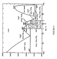
- Figures 4 is a binary phase diagram showing the yttria-silica system utilized in exemplary embodiments of this invention.
- Figure 5 is an x-ray diffraction pattern of a hot-pressed 36-64 mole percent Y 2 O 3 -SiO 2 solid body utilized to verify the desirability of a composition utilized in embodiments of this invention
- Figure 6 is an x-ray diffraction pattern of a 36-64 mole percent Y 2 O 3- SiO 2 coating that was thermal sprayed onto a silicon nitride substrate at about 1090°C, then cooled, showing undesirable non-equilibrium phases and amorphous structure therein;
- Figure 7 is an x-ray diffraction pattern of a 36-64 mole percent Y 2 O 3- SiO 2 coating that was thermal sprayed onto a silicon nitride substrate at about 1090°C, and then heat treated at a temperature of about 1200°C for about 1 hour, showing that some of the undesirable amorphous structure converted to undesirable non-equilibrium crystalline phases;
- Figure 8 is an x-ray diffraction pattern of a 36-64 mole percent Y 2 O 3- SiO 2 coating that was thermal sprayed onto a silicon nitride substrate at about 1300°C and held there for about 1 hour before first cooling, showing substantially only desirable equilibrium phases therein.
- FIGURES 1-8 For the purposes of promoting an understanding of the invention, reference will now be made to some embodiments of this invention as illustrated in FIGURES 1-8 and specific language used to describe the same.
- the terminology used herein is for the purpose of description, not limitation. Specific structural and functional details disclosed herein are not to be interpreted as limiting, but merely as a basis for teaching one skilled in the art to variously employ the present invention. Any modifications or variations in the depicted structures and methods, and such further applications of the principles of the invention as illustrated herein, as would normally occur to one skilled in the art, are considered to be within the spirit and scope of this invention as described and claimed.
- This invention relates to protective coatings that comprise substantially only specific equilibrium phases therein. These coatings have a coefficient of thermal expansion (CTE) that is substantially equal to the CTE of the substrate upon which the coatings are deposited.
- CTE coefficient of thermal expansion
- the desired phases and/or CTEs of these coatings can be obtained by controlling the application of these coatings and/or by heat treating the coated substrates to create the desired phases and/or microstructure in the coatings disposed thereon, as more fully described below.
- a difference of about +/- 1 ppm/°C in the CTE between the substrate and the coating will result in a strain of about 0.1 % over a temperature range of about 1000°C.
- the room temperature strain to failure for most brittle materials is about 0.1% in tension.
- a brittle ceramic coating will tend to crack on cooling if its CTE differs from that of the substrate by more than about 1 ppm/°C. Therefore, embodiments of these coatings have a CTE that is within about +/- 1 ppm/°C, more preferably within about +/- 0.3 ppm/°C, or even more preferably within about +/- 0.1 ppm/°C, of the CTE of the substrate the coating is used on.
- “equilibrium phases” and “equilibrium crystalline phases” refers: (1) to phases that do not change if they are heated to a temperature below the temperature at which they were processed at or quenched from (i.e., about 1500°C in some embodiments) for an amount of time similar to the expected, intended or actual useful life of the application; (2) to phases that, after fabrication/processing, do not change when exposed to expected, intended or actual application conditions; or (3) to phases that, even if they do change, do not affect the integrity of the coating (i.e., the phases before and after the change have equivalent thermal and physical properties). Trace amounts of impurities may be present in addition to the desired equilibrium phases.
- These protective coatings may be used on various substrates as environmental barrier coatings, thermal barrier coatings, and/or as barriers that inhibit the formation of gaseous species of silicon, particularly, Si(OH) x , when exposed to high temperature aqueous (i.e., water, steam) environments such as those found in gas turbine and combustion environments.
- high temperature aqueous (i.e., water, steam) environments such as those found in gas turbine and combustion environments.
- Embodiments of these protective coatings comprise any suitable material having the desired equilibrium phases and having a CTE that sufficiently matches that of the substrate. These protective coatings may also comprise minor amounts of impurities (i.e., less than about 10 volume percent) and/or dopants (i.e., less than about 5 volume percent). In some embodiments, these protective coatings comprise rare-earth-silicates (i.e., monosilicates, disilicates, etc.).
- rare earth includes yttrium, scandium, and the lanthanides (lutetium, lanthanum, cerium, praseodymium, neodymium, promethium, samarium, europium, gadolinium, terbium, dysprosium, holmium, erbium, thulium, and ytterbium).
- the CTE of the protective coating may be within +/- 1 ppm/°C of the CTE of the substrate.
- these protective coatings may be utilized as part of a multi-layered protective coating system 40 on a substrate 20, with each layer 42, 44, 46 comprising a different CTE, as shown in one exemplary embodiment in Figure 1.
- a first layer 42 having a lower CTE i.e., about 3.5 ppm/°C
- a top layer 46 having a higher CTE
- a middle layer 44 having an intermediate CTE (i.e., about 6 ppm/°C).
- the multi-layered protective coating system 40 may be of any suitable thickness and in embodiments, each layer of the multi-layered protective coating system 40 may be about 0.1-500 microns thick, more preferably about 1-250 microns thick, and even more preferably, about 20-150 microns thick. Any number of layers may be used in the protective coatings 40 of this invention.
- these protective coatings may comprise a single graded protective coating layer 48 that has a graded composition from one surface to the other, as shown in one exemplary embodiment in Figure 2.
- the graded coating 48 may comprise a continuously graded SiO 2 -Y 2 O 3 coating ranging from about 60-100 mole % SiO 2 (about 0-40 mole % Y 2 O 3 ) near its inner surface 41 to about 45-100 mole % Y 2 O 3 (about 0-55 mole % SiO 2 ) near its outer surface 49.
- the graded protective coating may be of any suitable thickness, and in embodiments, may be up to about 2000 microns thick.
- These protective coatings may be applied to the substrate 20 in any suitable manner, such as, for example, by thermal spraying (i.e., air plasma spraying, low pressure plasma spraying, high velocity oxy-fuel spraying, combustion spraying, solution spraying, etc.), chemical vapor deposition, physical vapor deposition, electrophoretic deposition, electrostatic deposition, sol-gel, slurry coating, dipping, air-brushing, sputtering, slurry painting, etc.
- thermal spraying i.e., air plasma spraying, low pressure plasma spraying, high velocity oxy-fuel spraying, combustion spraying, solution spraying, etc.
- chemical vapor deposition physical vapor deposition
- electrophoretic deposition electrophoretic deposition
- electrostatic deposition sol-gel
- sol-gel sol-gel
- slurry coating dipping, air-brushing, sputtering, slurry painting, etc.
- the processing should result in a coating structure having very low stresses (i.e., comprising very low amounts of non-equilibrium phases that may subsequently convert to equilibrium phases and create stresses in the protective coating) so as to avoid cracking or spalling of the coating, etc.
- the substrates 20 may comprise any suitable material, such as, for example, silicon-containing substrates (i.e., silicon-containing ceramics, silicon-containing metal alloys, etc.) and fiber reinforced oxide ceramic substrates.
- silicon-containing ceramics include, but are not limited to, ceramics containing silicon nitride, silicon carbide, silicon carbide composites, silicon nitride composites, silicon oxynitrides, silicon aluminum oxynitrides, silicon nitride ceramic matrix composites, and fiber reinforced silicon carbide ceramic matrix composites, etc.
- Suitable silicon-containing metal alloys include, but are not limited to, molybdenum silicon alloys, niobium silicon alloys, iron silicon alloys, cobalt silicon alloys, nickel silicon alloys, tantalum silicon alloys, refractory metal silicide alloys, etc.
- Suitable fiber reinforced oxide ceramic substrates comprise a ceramic matrix with a reinforcing phase embedded therein and include, but are not limited to, matrices comprising alumina, zirconium oxide, mullite, and/or monazite, etc., reinforced with fibers comprising silicon carbide, silicon nitride, alumina, mullite, monazite, and/or carbon, etc.
- a bond coat 30 may be disposed on the substrate 20.
- This bond coat 30 may comprise any suitable material, such as, for example, silicon, MoSi 2 , a refractory metal silicide, a refractory metal, and other refractory metal oxide forming silicides, and/or combinations thereof, etc.
- These bond coats 30 may be applied to the substrate 20 in any suitable manner, such as, for example, by thermal spray, sputtering, chemical vapor deposition, physical vapor deposition, etc.
- These bond coats 30 may be of any suitable thickness, and in embodiments, may be about 0.1-250 microns thick, more preferably about 0.5-100 microns thick, and even more preferably, about 1-50 microns thick. Bond coats 30 are typically used on silicon-containing substrates, but may not be needed on fiber reinforced oxide ceramic substrates.
- a topcoat 50 may be disposed on the protective coating 40, 48.
- This topcoat 50 may comprise any suitable material, such as, for example, rare earth oxides, hafnium oxide, zirconium oxide, yttrium oxide, aluminum oxide, tantalum oxide, niobium oxide, mullite, alkaline earth aluminosilicates, barium aluminosilicates, strontium aluminosilicates, titanium oxide, silicon dioxide, rare earth phosphates, aluminium phosphates, and/or combinations thereof, etc.
- topcoats 50 may be applied to the protective coating 40, 48 in any suitable manner, such as, for example, by thermal spraying, chemical vapor deposition, physical vapor deposition, electrophorectic deposition, electrostatic deposition, sol-gel, slurry coating, sputtering, dipping, spray painting, etc.
- These topcoats 40 may be of any suitable thickness, and in embodiments, may be about 1-250 microns thick, more preferably about 10-150 microns thick, and even more preferably, about 20-100 microns thick.
- one or more intermediate layers may be disposed either between the substrate 20 and the protective coating 40, 48, or between the protective coating 40, 48 and the topcoat 50. Such intermediate layers may provide enhanced adhesion between the substrate 20 and the protective coating 40, 48 and/or between the protective coating 40, 48 and the topcoat 50. Such intermediate layers may also prevent reactions between the substrate 20 and the protective coating 40, 48 and/or between the protective coating 40, 48 and the topcoat 50.
- These intermediate layers may comprise any suitable materials, such as, for example, SiO 2 , mullite, alkaline earth aluminosilicates, barium aluminosilicate, strontium aluminosilicate, barium strontium aluminosilicate, yttrium silicates, calcium aluminosilicate, silicon metal, rare earth oxides, hafnium oxide, zirconium oxide, titanium oxide, yttrium oxide, aluminum oxide, tantalum oxide, niobium oxide, rare earth phosphates, aluminium phosphates, and/or combinations thereof, etc.
- suitable materials such as, for example, SiO 2 , mullite, alkaline earth aluminosilicates, barium aluminosilicate, strontium aluminosilicate, barium strontium aluminosilicate, yttrium silicates, calcium aluminosilicate, silicon metal, rare earth oxides, hafnium oxide,
- These intermediate layers may be applied in any suitable manner, such as, for example, by thermal spraying, chemical vapor deposition, physical vapor deposition, sol-gel, slurry coating, electrophoretic deposition, electrostatic deposition, sputtering, dipping, etc.
- These intermediate layers may be of any suitable thickness, and in embodiments, may be about 1-250 microns thick, more preferably about 10-150 microns thick, and even more preferably, about 20-100 microns thick.
- the coated substrate can be heat treated to create the desired phases and/or microstructure therein.
- the desired equilibrium phases may exist in the coating after it is deposited, so there may be no need for heat treating such coated substrates.
- the coated substrates may require heat treatment to create the desired phases/microstructure therein.
- the heat treatment may vary according to which coatings, substrates and coating processes are used.
- the heat treatment may comprise heating the coated substrate to about 1100-1600°C for about 15-600 minutes.
- the final coating should comprise less than about 25 volume percent, more preferably less than about 10 volume percent, and even more preferably less than about 1 volume percent, of non-equilibrium phases in the coating. In embodiments, substantially only equilibrium phases exist in the coating, but dopants (i.e., less than about 5 volume percent) and/or minor impurities (i.e., less than about 10 volume percent) may also be present.
- a suitable yttrium silicate coating was identified for use on a silicon nitride substrate.
- Silicon nitride has a CTE of about 3.5 ppm/°C for room temperature to 1200°C. Since the CTE of yttrium silicate is generally determined by the ratio of yttria and silica present, and by the equilibrium phase content achieved by that ratio of yttria and silica, a yttrium silicate composition having a CTE close to that of the silicon nitride substrate can be selected by referring to Figure 3, where the effect of the yttria:silica ratio on the CTE of the yttrium silicate composition is shown.
- a composition comprising about 62-66 mole percent silica (SiO 2 ), or alternatively stated, about 34-38 mole percent yttria (Y 2 O 3 ), is desirable.
- the yttria-silica phase diagram shown in Figure 4 can be used to identify the equilibrium phases of yttria and silica that will be present at a given temperature in compositions comprising various mole percents of yttria and silica.
- the phases shown in Figure 4 for the 1500°C isotherm are expected to exist at room temperature.
- Equilibrium crystalline phases are desired because any non-equilibrium crystalline and/or amorphous phases that are present may undergo phase transformations during subsequent processing or upon exposure to high operating temperatures, or they may exhibit CTEs other than those observed for equilibrium phases. Such phase changes may be accompanied by volume changes, which may lead to cracking and disruption of the coating, causing problems similar to the problems encountered when the CTEs of the coating and substrate are mismatched too much.
- an equilibrated solid body comprising about 36 mole percent Y 2 O 3 and about 64 mole percent SiO 2 was fabricated by hot pressing.
- This solid body had the equilibrated structures indicated in Figure 5.
- this body exhibited the desirable 1:1 and 1:2 mole ratio phases, 80 and 90 respectively, and had a CTE of about 4 ppm/°C, thereby verifying that the 36-64 mole percent Y 2 O 3 -SiO 2 composition would be desirable for use as a coating on silicon nitride substrates.
- This 36-64 mole percent Y 2 O 3 -SiO 2 composition is also desirable because yttrium silicate exhibits good high temperature steam stability, and its CTE can be adjusted by altering the ratio of yttria and silica present.
- a coating comprising the 36:64 mole ratio Y 2 O 3 -SiO 2 composition was thermal sprayed via air plasma spray onto a silicon nitride substrate to create a coating about 20-150 microns thick.
- this coating exhibited both the 1:1 and 1:2 phases seen in Figure 5, 80 and 90 respectively, along with a substantial amount (about 62%) of amorphous structure that was not equilibrated.
- This amorphous phase content is undesirable and very deleterious to the coating integrity since it will exhibit a CTE different from the desired CTE, and will also undergo further phase change on subsequent thermal exposure, both of which will likely lead to cracking and spalling of the coating.
- the 36:64 mole ratio Y 2 O 3 -SiO 2 coating was thermal sprayed via air plasma spray onto the silicon nitride substrate using the above-noted spray parameters, but spraying the coating onto the substrate at about 1200°C and holding the coated substrate at about 1200°C for about 1 hour before first cooling.
- Standard x-ray crystallography techniques were then used to identify and/or confirm which phases were present in the final coating. As shown in Figure 7, this method created a structure having the desirable 1:1 and 1:2 equilibrium phases present, 80 and 90 respectively, with no amorphous content, but also having undesirable non-equilibrium 7:9 and 1:2 mole ratio phases present, 60 and 70 respectively. Therefore, another attempt was made to eliminate these undesirable phases.
- a 36:64 mole ratio Y 2 O 3 -SiO 2 coating was thermal sprayed onto another silicon nitride substrate using the above-noted spray parameters, but this time spraying the coating onto the substrate at about 1300°C and holding the coated substrate at about 1300°C for about 1 hour before first cooling.
- standard x-ray crystallography techniques were then used to identify and/or confirm which phases were present in this final coating. As shown in Figure 8, this method created a structure having substantially only the desirable 1:1 and 1:2 equilibrium phases present, 80 and 90 respectively, with no amorphous content.
- this yttrium silicate coating should be deposited on the silicon nitride substrate at a temperature of about 1000-1300°C, more preferably at about 1250-1300°C. They also indicated that this coated substrate should be heat treated at about 1100-1300°C for about 5-500 minutes, more preferably at about 1250-1300°C for about 15-60 minutes, to obtain the desired equilibrium phases.
- this invention provides protective coatings that have desired phases/microstructure therein.
- these protective coatings have a CTE within about +/- 1 ppm/°C of the CTE of the substrate they are used on.
- rare-earth-silicate coatings on silicon nitride substrates were described in one exemplary embodiment of this invention, many other coatings and substrates may be utilized with this invention.
- Suitable coating compositions can be identified for use on various substrates in a manner similar to that just discussed for yttrium silicate coatings on silicon nitride substrates, and all such embodiments are within the scope of this invention, so long as the desired phases are present in the coating.
Abstract
Description
- The U.S. Government may have certain rights in this invention pursuant to Contract Number N00014-01-C-0032 with the United States Office of Naval Research.
- The present invention relates generally to protective coatings, especially protective coatings for use on gas turbine engine components.
- Silicon carbide, silicon nitride, and other silica forming ceramics exhibit accelerated oxidation and recession in high temperature aqueous environments such as those found in combustor and turbine sections of gas turbine engines. It is believed that such material recession occurs because SiO2 forming materials react with the water vapor at high temperatures, which leads to volatilization of the silica in the form of Si(OH)x. Accordingly, protective coatings such as environmental barrier coatings (EBCs) may be used on components comprising such materials to slow the oxidation and recession and thereby increase the useful service life thereof.
- While protective coatings have been developed for use on silicon carbide substrates, these coatings are not acceptable for use on certain monolithic silicon-containing substrates having lower coefficients of thermal expansion than silicon carbide (i.e., silicon nitride). Therefore, it would be desirable to have protective coatings that are capable of being used on silicon-containing substrates having lower coefficients of thermal expansion than silicon carbide. It would also be desirable to have protective coatings that have coefficients of thermal expansion that match those of the substrates they are used on, so as to create stable, crack-free structures. It would be further desirable to have protective coatings that inhibit the formation of volatile silicon species, particularly Si(OH)x, in high temperature, aqueous environments. It would be yet further desirable to have protective coatings that provide thermal protection to the substrates they are used on. It would be even further desirable to have such protective coatings for use on silicon nitride substrates and/or on ceramic matrix composite substrates. It would be still further desirable to have improved methods for selecting suitable protective coatings for various substrates.
- Furthermore, steam-stable, coefficient of thermal expansion compatible coatings for ceramic substrates often contain complex silicates, and the coating processes used to deposit these coatings on such substrates often result in amorphous phases and/or metastable phases in the coatings that subsequently change to equilibrium phases during or after use. Such changes may render the coatings unprotective, and therefore, undesirable. Therefore, it would be desirable to ensure that equilibrium phases exist in such coatings, prior to, during and after use, so that optimum protection is provided to the substrate.
- The above-identified shortcomings of existing protective coatings and methods of selecting same are overcome by embodiments of the present invention, which relates to protective coatings that can be used on various substrates such as silicon-containing substrates having lower coefficients of thermal expansion than silicon carbide. Adjusting the coating chemistry can result in coatings that are appropriate for use on both silicon carbide and silicon nitride substrates. These protective coatings may be utilized on various components, such as, but not limited to, gas turbine engine components.
- Embodiments of this invention relate to articles comprising a substrate and a coating disposed on the substrate, the coating comprising predetermined equilibrium phases therein. The article may comprise a gas turbine engine component. In embodiments, the coating may comprise less than about 25 volume percent of non-equilibrium phases. In embodiments, the predetermined equilibrium phases may be crystalline phases and may comprise a 1:1 mole ratio rare-earth-oxide:silica, a 1:2 mole ratio rare-earth-oxide:silica, a rare earth oxide, silica and/or mixtures thereof. In embodiments, the coating may have a coefficient of thermal expansion within about +/- 1 ppm/°C of a coefficient of thermal expansion of the substrate.
- The coating may comprise a rare earth monosilicate, a rare earth disilicate, a rare earth oxide, silica, and/or mixtures thereof. The coating may comprise a multi-layered protective coating system or a single layer graded protective coating system. The coating may be about 0.1-2000 microns thick.
- In some embodiments, the predetermined equilibrium phases may exist in the coating after the coating is deposited. In other embodiments, after the coating is deposited, and prior to first cooling, the article may need to be heat treated to produce the predetermined equilibrium phases in the coating.
- In embodiments, the article may further comprise a bond coat between the substrate and the coating, one or more intermediate layers between the bond coat and the coating, a topcoat disposed on the coating, and/or one or more intermediate layers between the coating and the topcoat.
- Embodiments of this invention also comprise coated substrates made by depositing a coating on a substrate at a predetermined temperature to create a coated substrate; and heat treating the coated substrate, prior to first cooling, at a time and temperature sufficient to produce predetermined equilibrium crystalline phases in the coating.
- In embodiments, the substrate may comprise silicon nitride, and the coating may comprise a yttrium silicate coating comprising about 30-38 mole percent Y2O3, balance substantially SiO2. The yttrium silicate coating may be deposited on the substrate at a temperature of about 1000-1500°C, and then, before first cooling, the coated substrate may be heat treated at about 1100-1600°C for about 15-600 minutes.
- Embodiments of this invention also comprise articles made by thermal spraying a yttrium silicate coating on a silicon nitride substrate at a temperature of about 1250-1300°C to create a coated substrate; and heat treating the coated substrate at about 1250-1300°C for about 15-60 minutes prior to first cooling to create equilibrium phases of 1:1 and 1:2 mole ratio Y2O3-SiO2 in the yttrium silicate coating.
- Further details of this invention will be apparent to those skilled in the art during the course of the following description.
- Embodiments of this invention are described herein below with reference to various figures, wherein like characters of reference designate like parts throughout the drawings, in which:
- Figure 1 is a schematic drawing showing a multiple layered coating system on a substrate, as utilized in embodiments of this invention;
- Figure 2 is a schematic drawing showing a continuously graded coating system on a substrate, as utilized in embodiments of this invention;
- Figure 3 is a graph showing the coefficient of thermal expansion of yttrium silicate as a function of the mole percent Y2O3 and SiO2, as utilized in exemplary embodiments of this invention;
- Figures 4 is a binary phase diagram showing the yttria-silica system utilized in exemplary embodiments of this invention;
- Figure 5 is an x-ray diffraction pattern of a hot-pressed 36-64 mole percent Y2O3-SiO2 solid body utilized to verify the desirability of a composition utilized in embodiments of this invention;
- Figure 6 is an x-ray diffraction pattern of a 36-64 mole percent Y2O3-SiO2 coating that was thermal sprayed onto a silicon nitride substrate at about 1090°C, then cooled, showing undesirable non-equilibrium phases and amorphous structure therein;
- Figure 7 is an x-ray diffraction pattern of a 36-64 mole percent Y2O3-SiO2 coating that was thermal sprayed onto a silicon nitride substrate at about 1090°C, and then heat treated at a temperature of about 1200°C for about 1 hour, showing that some of the undesirable amorphous structure converted to undesirable non-equilibrium crystalline phases; and
- Figure 8 is an x-ray diffraction pattern of a 36-64 mole percent Y2O3-SiO2 coating that was thermal sprayed onto a silicon nitride substrate at about 1300°C and held there for about 1 hour before first cooling, showing substantially only desirable equilibrium phases therein.
- For the purposes of promoting an understanding of the invention, reference will now be made to some embodiments of this invention as illustrated in FIGURES 1-8 and specific language used to describe the same. The terminology used herein is for the purpose of description, not limitation. Specific structural and functional details disclosed herein are not to be interpreted as limiting, but merely as a basis for teaching one skilled in the art to variously employ the present invention. Any modifications or variations in the depicted structures and methods, and such further applications of the principles of the invention as illustrated herein, as would normally occur to one skilled in the art, are considered to be within the spirit and scope of this invention as described and claimed.
- This invention relates to protective coatings that comprise substantially only specific equilibrium phases therein. These coatings have a coefficient of thermal expansion (CTE) that is substantially equal to the CTE of the substrate upon which the coatings are deposited. The desired phases and/or CTEs of these coatings can be obtained by controlling the application of these coatings and/or by heat treating the coated substrates to create the desired phases and/or microstructure in the coatings disposed thereon, as more fully described below. A difference of about +/- 1 ppm/°C in the CTE between the substrate and the coating will result in a strain of about 0.1 % over a temperature range of about 1000°C. The room temperature strain to failure for most brittle materials is about 0.1% in tension. Thus, a brittle ceramic coating will tend to crack on cooling if its CTE differs from that of the substrate by more than about 1 ppm/°C. Therefore, embodiments of these coatings have a CTE that is within about +/- 1 ppm/°C, more preferably within about +/- 0.3 ppm/°C, or even more preferably within about +/- 0.1 ppm/°C, of the CTE of the substrate the coating is used on.
- As used herein and throughout, "equilibrium phases" and "equilibrium crystalline phases" refers: (1) to phases that do not change if they are heated to a temperature below the temperature at which they were processed at or quenched from (i.e., about 1500°C in some embodiments) for an amount of time similar to the expected, intended or actual useful life of the application; (2) to phases that, after fabrication/processing, do not change when exposed to expected, intended or actual application conditions; or (3) to phases that, even if they do change, do not affect the integrity of the coating (i.e., the phases before and after the change have equivalent thermal and physical properties). Trace amounts of impurities may be present in addition to the desired equilibrium phases.
- These protective coatings may be used on various substrates as environmental barrier coatings, thermal barrier coatings, and/or as barriers that inhibit the formation of gaseous species of silicon, particularly, Si(OH)x, when exposed to high temperature aqueous (i.e., water, steam) environments such as those found in gas turbine and combustion environments.
- Embodiments of these protective coatings comprise any suitable material having the desired equilibrium phases and having a CTE that sufficiently matches that of the substrate. These protective coatings may also comprise minor amounts of impurities (i.e., less than about 10 volume percent) and/or dopants (i.e., less than about 5 volume percent). In some embodiments, these protective coatings comprise rare-earth-silicates (i.e., monosilicates, disilicates, etc.). As used herein and throughout, "rare earth" includes yttrium, scandium, and the lanthanides (lutetium, lanthanum, cerium, praseodymium, neodymium, promethium, samarium, europium, gadolinium, terbium, dysprosium, holmium, erbium, thulium, and ytterbium). In some embodiments, the CTE of the protective coating may be within +/- 1 ppm/°C of the CTE of the substrate.
- In embodiments, these protective coatings may be utilized as part of a multi-layered
protective coating system 40 on asubstrate 20, with eachlayer first layer 42 having a lower CTE (i.e., about 3.5 ppm/°C), atop layer 46 having a higher CTE (i.e., about 7 ppm/°C), and amiddle layer 44 having an intermediate CTE (i.e., about 6 ppm/°C). The multi-layeredprotective coating system 40 may be of any suitable thickness and in embodiments, each layer of the multi-layeredprotective coating system 40 may be about 0.1-500 microns thick, more preferably about 1-250 microns thick, and even more preferably, about 20-150 microns thick. Any number of layers may be used in theprotective coatings 40 of this invention. - In other embodiments, these protective coatings may comprise a single graded
protective coating layer 48 that has a graded composition from one surface to the other, as shown in one exemplary embodiment in Figure 2. For example, the gradedcoating 48 may comprise a continuously graded SiO2-Y2O3 coating ranging from about 60-100 mole % SiO2 (about 0-40 mole % Y2O3) near itsinner surface 41 to about 45-100 mole % Y2O3 (about 0-55 mole % SiO2) near itsouter surface 49. Numerous other grading arrangements are also possible. The graded protective coating may be of any suitable thickness, and in embodiments, may be up to about 2000 microns thick. - These protective coatings may be applied to the
substrate 20 in any suitable manner, such as, for example, by thermal spraying (i.e., air plasma spraying, low pressure plasma spraying, high velocity oxy-fuel spraying, combustion spraying, solution spraying, etc.), chemical vapor deposition, physical vapor deposition, electrophoretic deposition, electrostatic deposition, sol-gel, slurry coating, dipping, air-brushing, sputtering, slurry painting, etc. These protective coatings should be applied at a temperature that facilitates the creation of the desired equilibrium phases in the coatings. However these protective coatings are applied, the processing should result in a coating structure having very low stresses (i.e., comprising very low amounts of non-equilibrium phases that may subsequently convert to equilibrium phases and create stresses in the protective coating) so as to avoid cracking or spalling of the coating, etc. - The
substrates 20 may comprise any suitable material, such as, for example, silicon-containing substrates (i.e., silicon-containing ceramics, silicon-containing metal alloys, etc.) and fiber reinforced oxide ceramic substrates. Suitable silicon-containing ceramics include, but are not limited to, ceramics containing silicon nitride, silicon carbide, silicon carbide composites, silicon nitride composites, silicon oxynitrides, silicon aluminum oxynitrides, silicon nitride ceramic matrix composites, and fiber reinforced silicon carbide ceramic matrix composites, etc. Suitable silicon-containing metal alloys include, but are not limited to, molybdenum silicon alloys, niobium silicon alloys, iron silicon alloys, cobalt silicon alloys, nickel silicon alloys, tantalum silicon alloys, refractory metal silicide alloys, etc. Suitable fiber reinforced oxide ceramic substrates comprise a ceramic matrix with a reinforcing phase embedded therein and include, but are not limited to, matrices comprising alumina, zirconium oxide, mullite, and/or monazite, etc., reinforced with fibers comprising silicon carbide, silicon nitride, alumina, mullite, monazite, and/or carbon, etc. - In embodiments, a
bond coat 30 may be disposed on thesubstrate 20. Thisbond coat 30 may comprise any suitable material, such as, for example, silicon, MoSi2, a refractory metal silicide, a refractory metal, and other refractory metal oxide forming silicides, and/or combinations thereof, etc. These bond coats 30 may be applied to thesubstrate 20 in any suitable manner, such as, for example, by thermal spray, sputtering, chemical vapor deposition, physical vapor deposition, etc. These bond coats 30 may be of any suitable thickness, and in embodiments, may be about 0.1-250 microns thick, more preferably about 0.5-100 microns thick, and even more preferably, about 1-50 microns thick. Bond coats 30 are typically used on silicon-containing substrates, but may not be needed on fiber reinforced oxide ceramic substrates. - In embodiments, a
topcoat 50 may be disposed on theprotective coating topcoat 50 may comprise any suitable material, such as, for example, rare earth oxides, hafnium oxide, zirconium oxide, yttrium oxide, aluminum oxide, tantalum oxide, niobium oxide, mullite, alkaline earth aluminosilicates, barium aluminosilicates, strontium aluminosilicates, titanium oxide, silicon dioxide, rare earth phosphates, aluminium phosphates, and/or combinations thereof, etc. Thesetopcoats 50 may be applied to theprotective coating topcoats 40 may be of any suitable thickness, and in embodiments, may be about 1-250 microns thick, more preferably about 10-150 microns thick, and even more preferably, about 20-100 microns thick. - In embodiments, one or more intermediate layers (not shown) may be disposed either between the
substrate 20 and theprotective coating protective coating topcoat 50. Such intermediate layers may provide enhanced adhesion between thesubstrate 20 and theprotective coating protective coating topcoat 50. Such intermediate layers may also prevent reactions between thesubstrate 20 and theprotective coating protective coating topcoat 50. These intermediate layers may comprise any suitable materials, such as, for example, SiO2, mullite, alkaline earth aluminosilicates, barium aluminosilicate, strontium aluminosilicate, barium strontium aluminosilicate, yttrium silicates, calcium aluminosilicate, silicon metal, rare earth oxides, hafnium oxide, zirconium oxide, titanium oxide, yttrium oxide, aluminum oxide, tantalum oxide, niobium oxide, rare earth phosphates, aluminium phosphates, and/or combinations thereof, etc. These intermediate layers may be applied in any suitable manner, such as, for example, by thermal spraying, chemical vapor deposition, physical vapor deposition, sol-gel, slurry coating, electrophoretic deposition, electrostatic deposition, sputtering, dipping, etc. These intermediate layers may be of any suitable thickness, and in embodiments, may be about 1-250 microns thick, more preferably about 10-150 microns thick, and even more preferably, about 20-100 microns thick. - If the desired equilibrium phases do not exist in the coating after it is deposited on the substrate, then the coated substrate can be heat treated to create the desired phases and/or microstructure therein. For example, if the substrate is coated via chemical vapor deposition, the desired equilibrium phases may exist in the coating after it is deposited, so there may be no need for heat treating such coated substrates. However, with other deposition methods, the coated substrates may require heat treatment to create the desired phases/microstructure therein.
- The heat treatment may vary according to which coatings, substrates and coating processes are used. In embodiments utilizing a yttrium silicate coating thermally sprayed onto a silicon nitride substrate, the heat treatment may comprise heating the coated substrate to about 1100-1600°C for about 15-600 minutes.
- Regardless of whether heat treated or not, the final coating should comprise less than about 25 volume percent, more preferably less than about 10 volume percent, and even more preferably less than about 1 volume percent, of non-equilibrium phases in the coating. In embodiments, substantially only equilibrium phases exist in the coating, but dopants (i.e., less than about 5 volume percent) and/or minor impurities (i.e., less than about 10 volume percent) may also be present.
- In one exemplary embodiment, a suitable yttrium silicate coating was identified for use on a silicon nitride substrate. Silicon nitride has a CTE of about 3.5 ppm/°C for room temperature to 1200°C. Since the CTE of yttrium silicate is generally determined by the ratio of yttria and silica present, and by the equilibrium phase content achieved by that ratio of yttria and silica, a yttrium silicate composition having a CTE close to that of the silicon nitride substrate can be selected by referring to Figure 3, where the effect of the yttria:silica ratio on the CTE of the yttrium silicate composition is shown. For example, as shown in Figure 3, if a CTE of about 4 ppm/°C is desired, a composition comprising about 62-66 mole percent silica (SiO2), or alternatively stated, about 34-38 mole percent yttria (Y2O3), is desirable. The yttria-silica phase diagram shown in Figure 4 can be used to identify the equilibrium phases of yttria and silica that will be present at a given temperature in compositions comprising various mole percents of yttria and silica. When the techniques of this invention are followed to produce a thermodynamically equilibrated structure at room temperature, the phases shown in Figure 4 for the 1500°C isotherm are expected to exist at room temperature. Equilibrium crystalline phases are desired because any non-equilibrium crystalline and/or amorphous phases that are present may undergo phase transformations during subsequent processing or upon exposure to high operating temperatures, or they may exhibit CTEs other than those observed for equilibrium phases. Such phase changes may be accompanied by volume changes, which may lead to cracking and disruption of the coating, causing problems similar to the problems encountered when the CTEs of the coating and substrate are mismatched too much.
- To determine if a 36-64 mole percent Y2O3-SiO2 composition would indeed produce the desired phases in a coating on a silicon nitride substrate, an equilibrated solid body comprising about 36 mole percent Y2O3 and about 64 mole percent SiO2 was fabricated by hot pressing. This solid body had the equilibrated structures indicated in Figure 5. As seen in the x-ray pattern in Figure 5, this body exhibited the desirable 1:1 and 1:2 mole ratio phases, 80 and 90 respectively, and had a CTE of about 4 ppm/°C, thereby verifying that the 36-64 mole percent Y2O3-SiO2 composition would be desirable for use as a coating on silicon nitride substrates. This 36-64 mole percent Y2O3-SiO2 composition is also desirable because yttrium silicate exhibits good high temperature steam stability, and its CTE can be adjusted by altering the ratio of yttria and silica present.
- Once this suitable 36:64 mole ratio Y2O3-SiO2 composition was verified, a coating comprising the 36:64 mole ratio Y2O3-SiO2 composition was thermal sprayed via air plasma spray onto a silicon nitride substrate to create a coating about 20-150 microns thick. The following thermal spray parameters were used:
Parameter Setting Gun 3M Nozzle GH Primary gas Argon Secondary gas Hydrogen Primary pressure (psi) 40 Secondary pressure (psi) 0 Current (amps) 600 Voltage (volts) 50 Powder port #2 - 80 mils Carrier gas Argon Carrier feed (psi) 40 Feeder RPM 3.85 Powder feedrate (g/min) 12 Stand off (inches) 4.75 Spray temperature (°C) 1300 Cycles 3 Thickness (mils) 4-5 Gun speed (inches/second) 6 - As shown in Figure 6, this coating exhibited both the 1:1 and 1:2 phases seen in Figure 5, 80 and 90 respectively, along with a substantial amount (about 62%) of amorphous structure that was not equilibrated. This amorphous phase content is undesirable and very deleterious to the coating integrity since it will exhibit a CTE different from the desired CTE, and will also undergo further phase change on subsequent thermal exposure, both of which will likely lead to cracking and spalling of the coating.
- In order to achieve a thermal sprayed 36:64 mole ratio Y2O3-SiO2 coating having the desired phases and CTE, certain critical conditions must be met during fabrication of the coating. Various attempts were made to determine these critical conditions, none of which required undue experimentation.
- First, the 36:64 mole ratio Y2O3-SiO2 coating was thermal sprayed via air plasma spray onto the silicon nitride substrate using the above-noted spray parameters, but spraying the coating onto the substrate at about 1200°C and holding the coated substrate at about 1200°C for about 1 hour before first cooling. Standard x-ray crystallography techniques were then used to identify and/or confirm which phases were present in the final coating. As shown in Figure 7, this method created a structure having the desirable 1:1 and 1:2 equilibrium phases present, 80 and 90 respectively, with no amorphous content, but also having undesirable non-equilibrium 7:9 and 1:2 mole ratio phases present, 60 and 70 respectively. Therefore, another attempt was made to eliminate these undesirable phases.
- In that regard, a 36:64 mole ratio Y2O3-SiO2 coating was thermal sprayed onto another silicon nitride substrate using the above-noted spray parameters, but this time spraying the coating onto the substrate at about 1300°C and holding the coated substrate at about 1300°C for about 1 hour before first cooling. As with the first attempt, standard x-ray crystallography techniques were then used to identify and/or confirm which phases were present in this final coating. As shown in Figure 8, this method created a structure having substantially only the desirable 1:1 and 1:2 equilibrium phases present, 80 and 90 respectively, with no amorphous content. As can also be seen in Figure 8, small amounts of the 7:9 mole ratio Y2O3-SiO2 system 60, and variations of the 1:2 mole ratio Y2O3-SiO2 system 70, were also present, but not in detrimental quantities.
- These and other trial attempts indicated that this yttrium silicate coating should be deposited on the silicon nitride substrate at a temperature of about 1000-1300°C, more preferably at about 1250-1300°C. They also indicated that this coated substrate should be heat treated at about 1100-1300°C for about 5-500 minutes, more preferably at about 1250-1300°C for about 15-60 minutes, to obtain the desired equilibrium phases. They also indicated that heat treating this 36-64 mole percent Y2O3-SiO2 coating/silicon nitride substrate system below about 1250°C is undesirable because a significant portion of the amorphous portion of the coating converts to the 7:9 mole ratio Y2O3-SiO2 system 60, plus additional variations of the 1:2 mole ratio Y2O3-SiO2 system 70, which creates an overall coating system of 1:1, 7:9 and variations of the 1:2 mole ratio Y2O3-SiO2 systems, as shown in Figure 7. These 7:9 and variations of the 1:2 mole ratio Y2O3-SiO2 systems, 60 and 70 respectively, are unstable, non-equilibrium phases that do not produce protective coatings that are suitable for use on silicon nitride. These 7:9 and variations of the 1:2 mole ratio Y2O3-SiO2 systems, 60 and 70 respectively, when present in large amounts, result in cracked coatings being formed due to the mismatch between the CTEs of the coating and the substrate.
- As described above, this invention provides protective coatings that have desired phases/microstructure therein. In embodiments, these protective coatings have a CTE within about +/- 1 ppm/°C of the CTE of the substrate they are used on. While rare-earth-silicate coatings on silicon nitride substrates were described in one exemplary embodiment of this invention, many other coatings and substrates may be utilized with this invention. Suitable coating compositions can be identified for use on various substrates in a manner similar to that just discussed for yttrium silicate coatings on silicon nitride substrates, and all such embodiments are within the scope of this invention, so long as the desired phases are present in the coating. For example, while coatings for substrates having a CTE less than that of silicon carbide were described, the principles of this invention could also be applied to substrates having a CTE greater than that of silicon carbide to determine suitable coatings therefor. These protective coatings may be utilized on gas turbine engine components and other components that operate in high temperature, aqueous environments. Advantageously, these protective coatings function as environmental barriers, thermal barriers, simple oxygen barriers, and/or transition layers. Many other embodiments and advantages will be apparent to those skilled in the relevant art.
- Various embodiments of this invention have been described in fulfillment of the various needs that the invention meets. It should be recognized that these embodiments are merely illustrative of the principles of various embodiments of the present invention. Numerous modifications and adaptations thereof will be apparent to those skilled in the art without departing from the spirit and scope of the present invention. Thus, it is intended that the present invention cover all suitable modifications and variations as come within the scope of the appended claims and their equivalents.
Claims (28)
- An article comprising:a substrate; anda coating disposed on the substrate, the coating comprising predetermined equilibrium phases therein.
- The article of claim 1, wherein the coating comprises less than about 25 volume percent of non-equilibrium phases.
- The article of claim 1, wherein the predetermined equilibrium phases are crystalline phases.
- The article of clam 1, wherein the predetermined equilibrium phases comprise at least one of: a 1:1 mole ratio rare-earth-oxide:silica, a 1:2 mole ratio rare-earth-oxide:silica, a rare earth oxide, silica, and mixtures thereof.
- The article of claim 1, wherein the coating has a coefficient of thermal expansion within about +/- 1 ppm/°C of a coefficient of thermal expansion of the substrate.
- The article of claim 1, wherein the substrate comprises at least one of: a silicon-containing substrate, a silicon-containing ceramic substrate, a silicon-containing metal alloy substrate, and a fiber reinforced oxide ceramic substrate.
- The article of claim 6, wherein the silicon ceramic substrate comprises at least one of: silicon nitride, silicon carbide, a silicon carbide composite, a silicon nitride composite, a silicon oxynitride, a silicon aluminum oxynitride, a silicon nitride ceramic matrix composite, and a fiber reinforced silicon carbide ceramic matrix composite.
- The article of claim 6, wherein the silicon-containing metal alloy substrate comprises at least one of: a molybdenum silicon alloy, a niobium silicon alloy, an iron silicon alloy, a cobalt silicon alloy, a nickel silicon alloy, a tantalum silicon alloy, and a refractory metal silicide alloy.
- The article of claim 6, wherein fiber reinforced oxide ceramic substrate comprises a ceramic matrix with a reinforcing phase embedded therein,
the ceramic matrix comprising at least one of: alumina, zirconium oxide, mullite, and monazite; and
the reinforcing phase comprising at least one of: silicon carbide, silicon nitride, alumina, mullite, monazite, and carbon. - The article of claim 1, wherein the coating comprises at least one of: a rare earth monosilicate, a rare earth disilicate, a rare earth oxide, silica, and mixtures thereof.
- The article of claim 1, wherein the coating comprises at least one of: a multi-layered protective coating system and a graded protective coating system.
- The article of claim 1, wherein the coating is about 0.1-2000 microns thick.
- The article of claim 1, wherein the coating is deposited on the substrate via at least one of: thermal spraying, chemical vapor deposition, physical vapor deposition, electrophoretic deposition, electrostatic deposition, sol-gel, slurry coating, dipping, air-brushing, sputtering, and slurry painting.
- The article of claim 1, wherein after the coating is deposited, the predetermined equilibrium phases exist in the coating.
- The article of claim 1, wherein after the coating is deposited, and prior to first cooling, the article is heat treated at a time and temperature sufficient to produce the predetermined equilibrium phases in the coating.
- The article of claim 1, wherein the substrate comprises a silicon nitride substrate and the coating comprises a yttrium silicate coating comprising about 30-38 mole percent Y2O3, balance substantially SiO2.
- The article of claim 16, wherein the yttrium silicate coating is deposited on the substrate at a temperature of about 1000-1500°C.
- The article of claim 17, wherein after the yttrium silicate coating is deposited on the silicon nitride substrate, and before first cooling, the article is heat treated at about 1100-1600°C for about 15-600 minutes.
- The article of claim 1, the article further comprising at least one of:a bond coat between the substrate and the coating;at least one intermediate layer between the bond coat and the coating;a topcoat disposed on the coating; andat least one intermediate layer between the coating and the topcoat.
- The article of claim 19, wherein the bond coat comprises at least one of: silicon, MoSi2, a refractory metal silicide, a refractory metal, a refractory metal oxide forming silicide, and combinations thereof.
- The article of claim 19, wherein any intermediate layers comprise at least one of: SiO2, mullite, an alkaline earth aluminosilicate, a barium aluminosilicate, a strontium aluminosilicate, a barium strontium aluminosilicate, a yttrium silicate, a calcium aluminosilicate, a silicon metal, a rare earth oxide, hafnium oxide, zirconium oxide, titanium oxide, yttrium oxide, aluminum oxide, tantalum oxide, niobium oxide, a rare earth phosphate, an aluminum phosphate, and/or combinations thereof.
- The article of claim 19, wherein the topcoat comprises at least one of: a rare earth oxide, hafnium oxide, zirconium oxide, yttrium oxide, aluminum oxide, tantalum oxide, niobium oxide, mullite, an alkaline earth aluminosilicate, a barium aluminosilicate, a strontium aluminosilicate, titanium oxide, silicon dioxide, a rare earth phosphate, an aluminium phosphate, and/or combinations thereof.
- The article of claim 1, wherein the article comprises a gas turbine engine component.
- A coated substrate made by a process comprising:depositing a coating on a substrate at a predetermined temperature to create a coated substrate; andheat treating the coated substrate, prior to first cooling, at a time and temperature sufficient to produce predetermined equilibrium crystalline phases in the coating.
- The coated substrate of claim 24, wherein the coating is deposited on the substrate via at least one of: thermal spraying, chemical vapor deposition, physical vapor deposition, electrophoretic deposition, electrostatic deposition, sol-gel, slurry coating, dipping, air-brushing, sputtering, and slurry painting.
- The coated substrate of claim 24, the process further comprising at least one of:applying a bond coat between the substrate and the coating;applying at least one intermediate layer between the bond coat and the coating;applying a topcoat on the coating; andapplying at least one intermediate layer between the coating and the topcoat.
- An article made by a process comprising:thermal spraying a yttrium silicate coating on a silicon nitride substrate at a temperature of about 1250-1300°C to create a coated substrate; andheat treating the coated substrate at about 1250-1300°C for about 15-60 minutes prior to first cooling to create equilibrium phases of 1:1 and 1:2 mole ratio Y2O3-SiO2 in the yttrium silicate coating.
- The article of claim 27, the process further comprising at least one of:applying a bond coat on the silicon nitride substrate prior to thermal spraying the yttrium silicate coating thereon;applying at least one intermediate layer between the bond coat and the yttrium silicate coating;applying a topcoat on the yttrium silicate coating prior to heat treating the coated substrate; andapplying at least one intermediate layer between the yttrium silicate coating and the topcoat.
Applications Claiming Priority (1)
| Application Number | Priority Date | Filing Date | Title |
|---|---|---|---|
| US10/992,992 US20060110609A1 (en) | 2004-11-19 | 2004-11-19 | Protective coatings |
Publications (2)
| Publication Number | Publication Date |
|---|---|
| EP1666626A1 true EP1666626A1 (en) | 2006-06-07 |
| EP1666626B1 EP1666626B1 (en) | 2008-07-16 |
Family
ID=35953975
Family Applications (1)
| Application Number | Title | Priority Date | Filing Date |
|---|---|---|---|
| EP05255776A Active EP1666626B1 (en) | 2004-11-19 | 2005-09-19 | Protective coatings |
Country Status (5)
| Country | Link |
|---|---|
| US (1) | US20060110609A1 (en) |
| EP (1) | EP1666626B1 (en) |
| JP (1) | JP2006143570A (en) |
| KR (1) | KR20060056229A (en) |
| DE (1) | DE602005008170D1 (en) |
Cited By (6)
| Publication number | Priority date | Publication date | Assignee | Title |
|---|---|---|---|---|
| CN101318841B (en) * | 2008-07-21 | 2011-04-20 | 景德镇陶瓷学院 | Zirconium kalium phosphate type high temperature purple ceramic pigment and preparation method |
| GB2427205B (en) * | 2005-06-13 | 2011-06-15 | Gen Electric | Bond coat for corrosion resistant EBC for silicon-containing substrate and processes for preparing same |
| WO2014022191A3 (en) * | 2012-08-03 | 2014-04-24 | General Electric Company | Hybrid air plasma spray and slurry method of environmental barrier deposition |
| WO2017031163A1 (en) * | 2015-08-18 | 2017-02-23 | General Electric Company | Dense environmental barrier coating compositions |
| WO2022006004A1 (en) * | 2020-06-30 | 2022-01-06 | Applied Materials, Inc. | Yttrium oxide based coating and bulk compositions |
| EP4191023A1 (en) * | 2021-12-06 | 2023-06-07 | General Electric Company | Environmental barrier coatings containing a rare earth disilicate and a second phase material |
Families Citing this family (51)
| Publication number | Priority date | Publication date | Assignee | Title |
|---|---|---|---|---|
| US7374825B2 (en) * | 2004-12-01 | 2008-05-20 | General Electric Company | Protection of thermal barrier coating by an impermeable barrier coating |
| US7449254B2 (en) * | 2005-01-21 | 2008-11-11 | General Electric Company | Environmental barrier coating with physical barrier layer for silicon-comprising materials |
| US7579087B2 (en) * | 2006-01-10 | 2009-08-25 | United Technologies Corporation | Thermal barrier coating compositions, processes for applying same and articles coated with same |
| EP1996341B1 (en) * | 2006-02-20 | 2018-09-26 | Kang N. Lee | Article including enviromental barrier coating system |
| US8138060B2 (en) | 2007-10-26 | 2012-03-20 | Shin-Etsu Chemical Co., Ltd. | Wafer |
| US9365725B2 (en) * | 2007-11-16 | 2016-06-14 | General Electric Company | Articles for high temperature service and methods for their manufacture |
| US20100025229A1 (en) * | 2008-07-30 | 2010-02-04 | Guardian Industries Corp. | Apparatus and method for sputtering target debris reduction |
| US20100069226A1 (en) * | 2008-09-17 | 2010-03-18 | General Electric Company | Rare earth phosphate bonded ceramics |
| WO2010039699A2 (en) * | 2008-09-30 | 2010-04-08 | Rolls-Royce Corporation | Coating including a rare earth silicate-based layer including a second phase |
| WO2010103530A1 (en) * | 2009-03-09 | 2010-09-16 | Godavari Biorefineries Ltd. | Method for producing ethanol by c-5 sugar fermenting saccharomyces strain |
| TWI403413B (en) * | 2009-04-27 | 2013-08-01 | Univ Tatung | Hydrophilic-hydrophobic transformable composite film and the method of fabricating the same |
| EP2543751A3 (en) * | 2009-07-16 | 2013-06-26 | MEMC Singapore Pte. Ltd. | Coated crucibles and methods for preparing and use thereof |
| US8147922B2 (en) * | 2009-09-18 | 2012-04-03 | General Electric Company | Composition and method for a thermal coating system |
| US8961767B2 (en) * | 2010-03-26 | 2015-02-24 | Colorado State University Research Foundation | Self-assembly of coatings utilizing surface charge |
| CN102093083B (en) * | 2010-12-06 | 2012-10-03 | 西北有色金属研究院 | Preparation method for ablation-resistant coating made of carbon/carbon composite material HfC |
| US8826725B2 (en) * | 2011-02-11 | 2014-09-09 | Ngk Spark Plug Co., Ltd. | Gas detector |
| TWI441962B (en) * | 2011-10-14 | 2014-06-21 | Sino American Silicon Prod Inc | Crystalline silicon ingot and method of fabricating the same |
| BR112015021737A2 (en) * | 2013-03-05 | 2017-07-18 | Gen Electric | high temperature operable ceramic matrix composite and method for manufacturing a high temperature operable turbine engine component |
| US10093810B2 (en) * | 2013-03-15 | 2018-10-09 | General Electric Company | Composite coatings and methods therefor |
| US9711334B2 (en) | 2013-07-19 | 2017-07-18 | Applied Materials, Inc. | Ion assisted deposition for rare-earth oxide based thin film coatings on process rings |
| US9583369B2 (en) | 2013-07-20 | 2017-02-28 | Applied Materials, Inc. | Ion assisted deposition for rare-earth oxide based coatings on lids and nozzles |
| US20150118444A1 (en) * | 2013-10-31 | 2015-04-30 | General Electric Company | Methods of manufacturing silica-forming articles having engineered surfaces to enhance resistance to creep sliding under high-temperature loading |
| US9725799B2 (en) * | 2013-12-06 | 2017-08-08 | Applied Materials, Inc. | Ion beam sputtering with ion assisted deposition for coatings on chamber components |
| US10022921B2 (en) * | 2013-12-19 | 2018-07-17 | General Electric Company | Turbine component patch delivery systems and methods |
| US9869013B2 (en) | 2014-04-25 | 2018-01-16 | Applied Materials, Inc. | Ion assisted deposition top coat of rare-earth oxide |
| US20170096732A1 (en) * | 2014-06-23 | 2017-04-06 | Hewlett-Packard Development Company, L.P. | Multilayer coatings on substrates |
| KR101635814B1 (en) * | 2014-09-12 | 2016-07-05 | 한국세라믹기술원 | Mold for extruding metal with excellent seizure resistance and method of manufacturing the same |
| US10329205B2 (en) | 2014-11-24 | 2019-06-25 | Rolls-Royce Corporation | Bond layer for silicon-containing substrates |
| DE102015100441A1 (en) * | 2015-01-13 | 2016-07-14 | Airbus Defence and Space GmbH | Structure or component for high-temperature applications and method and apparatus for producing the same |
| KR102106679B1 (en) * | 2015-03-13 | 2020-05-04 | 프랙스에어 에스.티. 테크놀로지, 인코포레이티드 | Chromate-free ceramic coating composition |
| US10047610B2 (en) * | 2015-09-08 | 2018-08-14 | Honeywell International Inc. | Ceramic matrix composite materials with rare earth phosphate fibers and methods for preparing the same |
| DE102016205702B4 (en) * | 2016-04-06 | 2017-12-14 | Siemens Healthcare Gmbh | X-ray detector with protective element and adhesive element |
| US11383494B2 (en) | 2016-07-01 | 2022-07-12 | General Electric Company | Ceramic matrix composite articles having different localized properties and methods for forming same |
| KR102419870B1 (en) * | 2017-07-13 | 2022-07-13 | 닛폰세이테츠 가부시키가이샤 | Grain-oriented electrical steel sheet and method for manufacturing grain-oriented electrical steel sheet |
| JP7045236B2 (en) * | 2018-03-27 | 2022-03-31 | 三菱重工業株式会社 | Thermal barrier coatings, turbine components and gas turbines |
| US11668198B2 (en) | 2018-08-03 | 2023-06-06 | Raytheon Technologies Corporation | Fiber-reinforced self-healing environmental barrier coating |
| US11535571B2 (en) * | 2018-08-16 | 2022-12-27 | Raytheon Technologies Corporation | Environmental barrier coating for enhanced resistance to attack by molten silicate deposits |
| US11505506B2 (en) | 2018-08-16 | 2022-11-22 | Raytheon Technologies Corporation | Self-healing environmental barrier coating |
| US20210198493A1 (en) * | 2018-08-22 | 2021-07-01 | Topy Kogyo Kabushiki Kaisha | Silicate-coated body |
| EP3842386A4 (en) * | 2018-08-22 | 2022-09-07 | Topy Kogyo Kabushiki Kaisha | Silicate coated body |
| KR102617370B1 (en) * | 2018-11-08 | 2023-12-26 | 삼성전자주식회사 | An electronic device comprising a housing including a plurality of layers |
| US11034842B2 (en) * | 2018-12-14 | 2021-06-15 | General Electric Company | Coating for improved surface finish |
| US11702728B2 (en) | 2019-05-28 | 2023-07-18 | Rolls-Royce Corporation | Post deposition heat treatment of coating on ceramic or ceramic matrix composite substrate |
| US20210017090A1 (en) * | 2019-07-19 | 2021-01-21 | Rolls-Royce Corporation | Thermal spray deposited coating |
| CN110578143B (en) * | 2019-09-30 | 2021-10-22 | 中国科学院金属研究所 | Preparation of Al-ZrO by atmospheric plasma spraying2/Y2O3Method for producing composite coating material |
| KR102163184B1 (en) * | 2019-11-29 | 2020-10-08 | 주식회사 쿠사 | Two-layer infrared radiator using REM-coated carbon fiber |
| KR102266656B1 (en) * | 2020-12-10 | 2021-06-18 | (주)코미코 | Yittrium granular powder for thermal spray and thermal spray coating produced using the same |
| KR102356029B1 (en) * | 2021-05-26 | 2022-02-08 | 주식회사 그린리소스 | Method for manufacturing silicate coating member |
| CN114276169A (en) * | 2021-12-30 | 2022-04-05 | 广东省科学院新材料研究所 | Self-healing high-density environmental barrier coating and preparation method and application thereof |
| CN115894000B (en) * | 2022-10-10 | 2023-07-07 | 武汉理工大学 | Mullite-titanium dioxide ceramic matrix composite coating, method, application and coating preparation method |
| CN115628646B (en) * | 2022-10-24 | 2023-10-24 | 陕西华秦科技实业股份有限公司 | High-temperature-resistant radar wave-absorbing material, method for preparing wave-absorbing coating by using same and application of material |
Citations (5)
| Publication number | Priority date | Publication date | Assignee | Title |
|---|---|---|---|---|
| EP1044944A1 (en) * | 1999-04-15 | 2000-10-18 | United Technologies Corporation | Silicon based substrate with yttrium silicate environmental/thermal barrier layer and method for preparing an article therefrom |
| US20020098391A1 (en) * | 2000-10-31 | 2002-07-25 | Kyocera Corporation | Surface-coated sintered body of silicon nitride |
| EP1479657A1 (en) * | 2003-05-22 | 2004-11-24 | United Technologies Corporation | Environmental barrier coating for silicon based substrates |
| EP1479658A2 (en) * | 2003-05-22 | 2004-11-24 | United Technologies Corporation | Bond layer for silicon based substrates |
| EP1479659A2 (en) * | 2003-05-22 | 2004-11-24 | United Technologies Corporation | Bond coating for silicon based substrates such as silicon nitride |
Family Cites Families (5)
| Publication number | Priority date | Publication date | Assignee | Title |
|---|---|---|---|---|
| US6254935B1 (en) * | 1999-04-15 | 2001-07-03 | United Technologies Corporation | Method for applying a barrier layer to a silicon based substrate |
| US6682821B2 (en) * | 2001-12-28 | 2004-01-27 | Kyocera Corporation | Corrosion-resistant ceramics |
| US6946096B2 (en) * | 2002-05-03 | 2005-09-20 | Honeywell International, Inc. | Use of powder metal sintering/diffusion bonding to enable applying silicon carbide or rhenium alloys to face seal rotors |
| US6733908B1 (en) * | 2002-07-08 | 2004-05-11 | The United States Of America As Represented By The Administrator Of The National Aeronautics And Space Administration | Multilayer article having stabilized zirconia outer layer and chemical barrier layer |
| US7323247B2 (en) * | 2003-11-21 | 2008-01-29 | Honeywell International, Inc. | Oxidation barrier coatings for silicon based ceramics |
-
2004
- 2004-11-19 US US10/992,992 patent/US20060110609A1/en not_active Abandoned
-
2005
- 2005-09-19 EP EP05255776A patent/EP1666626B1/en active Active
- 2005-09-19 DE DE602005008170T patent/DE602005008170D1/en active Active
- 2005-09-20 JP JP2005272587A patent/JP2006143570A/en active Pending
- 2005-09-20 KR KR1020050087455A patent/KR20060056229A/en not_active Application Discontinuation
Patent Citations (6)
| Publication number | Priority date | Publication date | Assignee | Title |
|---|---|---|---|---|
| EP1044944A1 (en) * | 1999-04-15 | 2000-10-18 | United Technologies Corporation | Silicon based substrate with yttrium silicate environmental/thermal barrier layer and method for preparing an article therefrom |
| US6312763B1 (en) * | 1999-04-15 | 2001-11-06 | United Technologies Corporation | Silicon based substrate with yttrium silicate environmental/thermal barrier layer |
| US20020098391A1 (en) * | 2000-10-31 | 2002-07-25 | Kyocera Corporation | Surface-coated sintered body of silicon nitride |
| EP1479657A1 (en) * | 2003-05-22 | 2004-11-24 | United Technologies Corporation | Environmental barrier coating for silicon based substrates |
| EP1479658A2 (en) * | 2003-05-22 | 2004-11-24 | United Technologies Corporation | Bond layer for silicon based substrates |
| EP1479659A2 (en) * | 2003-05-22 | 2004-11-24 | United Technologies Corporation | Bond coating for silicon based substrates such as silicon nitride |
Cited By (9)
| Publication number | Priority date | Publication date | Assignee | Title |
|---|---|---|---|---|
| GB2427205B (en) * | 2005-06-13 | 2011-06-15 | Gen Electric | Bond coat for corrosion resistant EBC for silicon-containing substrate and processes for preparing same |
| CN101318841B (en) * | 2008-07-21 | 2011-04-20 | 景德镇陶瓷学院 | Zirconium kalium phosphate type high temperature purple ceramic pigment and preparation method |
| WO2014022191A3 (en) * | 2012-08-03 | 2014-04-24 | General Electric Company | Hybrid air plasma spray and slurry method of environmental barrier deposition |
| WO2017031163A1 (en) * | 2015-08-18 | 2017-02-23 | General Electric Company | Dense environmental barrier coating compositions |
| CN107922280A (en) * | 2015-08-18 | 2018-04-17 | 通用电气公司 | Fine and close barrier of environment coating composition |
| CN107922280B (en) * | 2015-08-18 | 2022-03-04 | 通用电气公司 | Dense environmental barrier coating composition |
| US11414356B2 (en) | 2015-08-18 | 2022-08-16 | General Electric Company | Dense environmental barrier coating compositions |
| WO2022006004A1 (en) * | 2020-06-30 | 2022-01-06 | Applied Materials, Inc. | Yttrium oxide based coating and bulk compositions |
| EP4191023A1 (en) * | 2021-12-06 | 2023-06-07 | General Electric Company | Environmental barrier coatings containing a rare earth disilicate and a second phase material |
Also Published As
| Publication number | Publication date |
|---|---|
| EP1666626B1 (en) | 2008-07-16 |
| US20060110609A1 (en) | 2006-05-25 |
| JP2006143570A (en) | 2006-06-08 |
| KR20060056229A (en) | 2006-05-24 |
| DE602005008170D1 (en) | 2008-08-28 |
Similar Documents
| Publication | Publication Date | Title |
|---|---|---|
| EP1666626A1 (en) | Protective coatings | |
| EP1764351A2 (en) | Silicon based substrate with hafnium silicate containing barrier layer | |
| EP1044944B1 (en) | Silicon based substrate with yttrium silicate environmental/thermal barrier layer and method for preparing an article therefrom | |
| US6787195B2 (en) | Method of depositing a coating on Si-based ceramic composites | |
| US6284325B1 (en) | Silicon based substrate with calcium aluminosilicate/thermal barrier layer | |
| KR100390289B1 (en) | Article comprising silicon based substrate with environmental/thermal barrier layer | |
| EP1595859B1 (en) | Article comprising a substrate comprising silicon and a top barrier layer comprising hafnium oxide | |
| EP1685083B1 (en) | Oxidation barrier coatings for silicon based ceramics | |
| EP1044947B1 (en) | Method for applying a barrier layer to a silicon based substrate and an article prepared in accordance with the method | |
| EP1323690B1 (en) | Barrier layer for silicon containing substrate | |
| EP1626040B1 (en) | Coating process to enable electrophoretic deposition | |
| US11905222B2 (en) | Environmental barrier coating for enhanced resistance to attack by molten silicate deposits | |
| US20240109813A1 (en) | Oxidation barrier materials and process for ceramic matrix composites | |
| WO2023200720A1 (en) | Environmental barrier materials and coatings containing low melting temperature phases | |
| Eaton Jr et al. | Silicon based substrate with yttrium silicate environmental/thermal barrier layer |
Legal Events
| Date | Code | Title | Description |
|---|---|---|---|
| PUAI | Public reference made under article 153(3) epc to a published international application that has entered the european phase |
Free format text: ORIGINAL CODE: 0009012 |
|
| AK | Designated contracting states |
Kind code of ref document: A1 Designated state(s): AT BE BG CH CY CZ DE DK EE ES FI FR GB GR HU IE IS IT LI LT LU LV MC NL PL PT RO SE SI SK TR |
|
| AX | Request for extension of the european patent |
Extension state: AL BA HR MK YU |
|
| 17P | Request for examination filed |
Effective date: 20060606 |
|
| 17Q | First examination report despatched |
Effective date: 20060714 |
|
| AKX | Designation fees paid |
Designated state(s): DE FR GB |
|
| 17Q | First examination report despatched |
Effective date: 20060714 |
|
| GRAP | Despatch of communication of intention to grant a patent |
Free format text: ORIGINAL CODE: EPIDOSNIGR1 |
|
| GRAS | Grant fee paid |
Free format text: ORIGINAL CODE: EPIDOSNIGR3 |
|
| GRAA | (expected) grant |
Free format text: ORIGINAL CODE: 0009210 |
|
| AK | Designated contracting states |
Kind code of ref document: B1 Designated state(s): DE FR GB |
|
| REG | Reference to a national code |
Ref country code: GB Ref legal event code: FG4D |
|
| REF | Corresponds to: |
Ref document number: 602005008170 Country of ref document: DE Date of ref document: 20080828 Kind code of ref document: P |
|
| PLBE | No opposition filed within time limit |
Free format text: ORIGINAL CODE: 0009261 |
|
| STAA | Information on the status of an ep patent application or granted ep patent |
Free format text: STATUS: NO OPPOSITION FILED WITHIN TIME LIMIT |
|
| 26N | No opposition filed |
Effective date: 20090417 |
|
| REG | Reference to a national code |
Ref country code: FR Ref legal event code: ST Effective date: 20090529 |
|
| PG25 | Lapsed in a contracting state [announced via postgrant information from national office to epo] |
Ref country code: FR Free format text: LAPSE BECAUSE OF NON-PAYMENT OF DUE FEES Effective date: 20080930 |
|
| REG | Reference to a national code |
Ref country code: DE Ref legal event code: R082 Ref document number: 602005008170 Country of ref document: DE Representative=s name: SCHMITT-NILSON SCHRAUD WAIBEL WOHLFROM PATENTA, DE |
|
| REG | Reference to a national code |
Ref country code: DE Ref legal event code: R082 Ref document number: 602005008170 Country of ref document: DE Representative=s name: SCHMITT-NILSON SCHRAUD WAIBEL WOHLFROM PATENTA, DE Ref country code: DE Ref legal event code: R081 Ref document number: 602005008170 Country of ref document: DE Owner name: UNITED TECHNOLOGIES CORP. (N.D.GES.D. STAATES , US Free format text: FORMER OWNER: UNITED TECHNOLOGIES CORPORATION, HARTFORD, CONN., US |
|
| PGFP | Annual fee paid to national office [announced via postgrant information from national office to epo] |
Ref country code: DE Payment date: 20190820 Year of fee payment: 15 |
|
| REG | Reference to a national code |
Ref country code: DE Ref legal event code: R119 Ref document number: 602005008170 Country of ref document: DE |
|
| PG25 | Lapsed in a contracting state [announced via postgrant information from national office to epo] |
Ref country code: DE Free format text: LAPSE BECAUSE OF NON-PAYMENT OF DUE FEES Effective date: 20210401 |
|
| PGFP | Annual fee paid to national office [announced via postgrant information from national office to epo] |
Ref country code: GB Payment date: 20230823 Year of fee payment: 19 |