EP3611092A1 - Wasserfahrzeug mit elektromotorischem jetantrieb - Google Patents
Wasserfahrzeug mit elektromotorischem jetantrieb Download PDFInfo
- Publication number
- EP3611092A1 EP3611092A1 EP19192051.1A EP19192051A EP3611092A1 EP 3611092 A1 EP3611092 A1 EP 3611092A1 EP 19192051 A EP19192051 A EP 19192051A EP 3611092 A1 EP3611092 A1 EP 3611092A1
- Authority
- EP
- European Patent Office
- Prior art keywords
- watercraft
- structural unit
- cooling water
- assembly
- battery
- Prior art date
- Legal status (The legal status is an assumption and is not a legal conclusion. Google has not performed a legal analysis and makes no representation as to the accuracy of the status listed.)
- Granted
Links
Images


Classifications
-
- B—PERFORMING OPERATIONS; TRANSPORTING
- B63—SHIPS OR OTHER WATERBORNE VESSELS; RELATED EQUIPMENT
- B63H—MARINE PROPULSION OR STEERING
- B63H21/00—Use of propulsion power plant or units on vessels
- B63H21/12—Use of propulsion power plant or units on vessels the vessels being motor-driven
- B63H21/17—Use of propulsion power plant or units on vessels the vessels being motor-driven by electric motor
-
- A—HUMAN NECESSITIES
- A63—SPORTS; GAMES; AMUSEMENTS
- A63B—APPARATUS FOR PHYSICAL TRAINING, GYMNASTICS, SWIMMING, CLIMBING, OR FENCING; BALL GAMES; TRAINING EQUIPMENT
- A63B35/00—Swimming framework with driving mechanisms operated by the swimmer or by a motor
- A63B35/08—Swimming framework with driving mechanisms operated by the swimmer or by a motor with propeller propulsion
- A63B35/12—Swimming framework with driving mechanisms operated by the swimmer or by a motor with propeller propulsion operated by a motor
-
- B—PERFORMING OPERATIONS; TRANSPORTING
- B63—SHIPS OR OTHER WATERBORNE VESSELS; RELATED EQUIPMENT
- B63B—SHIPS OR OTHER WATERBORNE VESSELS; EQUIPMENT FOR SHIPPING
- B63B32/00—Water sports boards; Accessories therefor
- B63B32/10—Motor-propelled water sports boards
-
- B—PERFORMING OPERATIONS; TRANSPORTING
- B63—SHIPS OR OTHER WATERBORNE VESSELS; RELATED EQUIPMENT
- B63C—LAUNCHING, HAULING-OUT, OR DRY-DOCKING OF VESSELS; LIFE-SAVING IN WATER; EQUIPMENT FOR DWELLING OR WORKING UNDER WATER; MEANS FOR SALVAGING OR SEARCHING FOR UNDERWATER OBJECTS
- B63C11/00—Equipment for dwelling or working underwater; Means for searching for underwater objects
- B63C11/46—Divers' sleds or like craft, i.e. craft on which man in diving-suit rides
-
- B—PERFORMING OPERATIONS; TRANSPORTING
- B63—SHIPS OR OTHER WATERBORNE VESSELS; RELATED EQUIPMENT
- B63H—MARINE PROPULSION OR STEERING
- B63H21/00—Use of propulsion power plant or units on vessels
- B63H21/38—Apparatus or methods specially adapted for use on marine vessels, for handling power plant or unit liquids, e.g. lubricants, coolants, fuels or the like
- B63H21/383—Apparatus or methods specially adapted for use on marine vessels, for handling power plant or unit liquids, e.g. lubricants, coolants, fuels or the like for handling cooling-water
-
- B—PERFORMING OPERATIONS; TRANSPORTING
- B63—SHIPS OR OTHER WATERBORNE VESSELS; RELATED EQUIPMENT
- B63H—MARINE PROPULSION OR STEERING
- B63H11/00—Marine propulsion by water jets
- B63H11/02—Marine propulsion by water jets the propulsive medium being ambient water
Definitions
- the present invention is directed to improving a watercraft, in particular a standing board such as a surfboard or wakeboard, with a jet drive with an electric motor drive and with an electrical energy store for the electric motor.
- An essential parameter for the safe operation of an electrically powered vehicle is the temperature of the battery that occurs during operation. If the battery is too warm, no more energy may be drawn, and in the worst case driving must be stopped or damage may occur.
- the drive and its control are currently permanently installed in the known electric watercraft.
- An error or defect that occurs cannot usually be repaired by the end user.
- he usually depends on a trained technician he then has to do a repair carry out on site at the customer, or the watercraft is brought to him for repair at a manufacturer's service center that is usually certified, or it is even sent to the manufacturer for repair.
- Repairs at the customer's site by a trained technician are not practical in most cases, since the technical infrastructure is usually lacking there, and personnel and travel costs are also immense. Repairing in a service facility creates the problem of transporting the product. A prerequisite for this is an expanded infrastructure with a sufficient number of service branches. This is very difficult to achieve with worldwide sales and is therefore also problematic.
- the only alternative is to send the product to the manufacturer.
- the product must first be packed securely for transport and then transported to the place of manufacture by a logistician. This procedure is not only cost-intensive, but also means that the customer waives the product for the duration of the repair.
- the present invention has for its object to provide a watercraft and a drive system therefor, the handling and in particular also ease of maintenance is improved. This object is achieved by a watercraft with the features of claim 1 and a drive system with the features of claim 10. Preferred configurations are specified in the subclaims.
- a watercraft according to the invention can, for example, be a standing board in the manner of a surfboard or wakeboard, that is, set up for a user or “pilot” standing thereon (and also, for example, with or without a binding, as is known for example from water skis or wakeboards) Feet) - but also a water or underwater vehicle, that is set up not only to stand on a very limited area of the vehicle, but also to move on or in it, to stand, or even (especially as an underwater vehicle such as an underwater scooter to tow a diver) to tow one or more people.
- the watercraft according to the invention is equipped with a jet drive with an electric motor drive and with an electrical energy store for the electric motor.
- the watercraft is characterized in that the jet drive and the electric motor drive are preferably also integrated in a (first) structural unit, but in any case, according to the invention, the energy store is in a separate (in particular second) structural unit.
- the second (and possibly also the first) unit is designed according to the invention to be assembled and disassembled as an integral unit (in particular pre-assembled and overall) in the watercraft.
- the energy storage unit can have a carrying handle which, for example, enables it to be carried upright close to the body.
- the structural units (in particular for integration into the construction of different watercraft) preferably have a common housing in which they can be assembled and disassembled (prepared, set up, adapted and / or suitably).
- the structural units can have a common housing, and they are prepared, set up, adapted and / or, in particular, can be fitted and removed from the housing in terms of their dimensions and connecting elements.
- housing is also a frame or scaffold that surrounds the structural units at least in certain areas.
- the first unit (or also power box), the second unit (or battery box) and possibly a storage compartment (8) as a possible third unit in a (possibly also consisting of several parts) recording unit or housings are mountable - which can be integrated together (especially as a system) into the construction of different watercraft (in particular hydrodynamic, propulsion-functional and / or regarding the statics of the watercraft), it is possible to use different watercraft, the same or similar watercraft of one type, but with different ones Offer hulls, lengths, buoyancy volumes, widths and / or underwater ships, as is known for example from surfboards - but with the same propulsion system according to the invention. As a result, the customer can always fall back on these same components and can use them in all of these products.
- the watercraft (such as a surfboard or wakeboard) can even be set up to be usable even without the drive according to the invention.
- replacement structural units which, for example, do not contain a drive device and no energy store
- the watercraft would then be usable again, for example, as a conventional surfboard or wakeboard - and can then be used again according to the invention by inserting the structural units according to the invention.
- the modular structure also enables the customer to replace individual components faster and with less effort in the event of a fault. This can be a quick exchange via local sales partners. Since the transport of batteries only in Passenger aircraft are usually not allowed, for example, a user can take their surfboard without a battery on vacation and borrow a battery from a sales partner on site, because the transport of the surfboard (without battery) is also permitted as sports luggage in passenger aircraft.
- the assembly of the second assembly blocks the disassembly of the first assembly and / or that the disassembly of the second assembly enables the disassembly of the first assembly.
- the assembly of a third structural unit (for example a storage compartment) blocks the dismantling of the second structural unit and / or the dismantling of the third structural unit enables the dismantling of the second structural unit.
- the blocked construction units can be more reliable due to their temporary inaccessibility.
- first structural unit power box
- This unit can then be fixed in position by installing a rear section.
- This structural unit and / or the stern part
- This structural unit can also have a region of an outer skin of the watercraft, namely in particular the region of the outer skin at the stern, which surrounds the outflow opening of the jet drive.
- the second and / or the third structural unit therefore preferably has a region of an outer skin of the watercraft.
- the watercraft according to the invention can be set up (for example in the form of a standing area, at least one foot binding and / or a seat) to accommodate a pilot of the watercraft.
- a drive emergency stop actuation device can be arranged in the area of the outer skin and within reach of the pilot of the watercraft.
- the second structural unit is prepared, set up, adapted and / or suitable to be mountable in a (suitably prepared, set up, adapted and / or suitable) housing in such a way that an unfilled cooling water cavity remains in the housing , which has an inlet for cooling water from an inlet opening.
- This can be arranged in an outer skin of the watercraft such that it is flown by the water during its journey and lets water into the cavity. It can be fed (for example in a transition area from the first to the second structural unit) but also, for example, from an outlet opening of cooling water of the jet drive (in particular then also, for example, also in a transition region from the first to the second structural unit) and thus in line with it stand or be settable.
- the cavity then also has an outlet for the cooling water from an outlet opening which is arranged in an outer skin of the watercraft in such a way that it releases the cooling water from the cavity as it moves.
- the drain can in particular be arranged in the top of the watercraft and in particular pass through a joint gap, for example between the outer skin area which is formed by the second structural unit used there and the outer skin of the watercraft which otherwise surrounds it.
- the cavity is then arranged in the housing in addition to the energy storage unit in such a way that heat from this unit can be exchanged with the cooling water in the cavity and removed from the cavity with the cooling water.
- a product line with the watercraft or propulsion system according to the invention can preferably (individually or in any combination) contain the following components and aspects: Hull: Different products are provided within a product range, all of which are identical to one another in the form of the receptacle for the power supply and drive unit. As a result, all components relating to the invention can be used in all products offered in the product range.
- Hull Different products are provided within a product range, all of which are identical to one another in the form of the receptacle for the power supply and drive unit.
- all components relating to the invention can be used in all products offered in the product range.
- a standardized mounting unit is installed in the various hulls within the intended product line.
- the shape of this recording unit is adapted to the power box, the battery box and the storage compartment.
- the acquisition unit ensures that all different hulls are compatible with the components described here.
- the power box, the battery box and the storage compartment can thus be used in
- Powerbox The components for the actual drive are built into the powerbox. These are essentially the jet, the engine, a speed controller and a connector.
- Battery compartment In addition to the battery, the battery box contains a battery management system (BMS), a receiver for remote control, a plug for emergency stop, a GPS receiver for the transmitter / receiver unit for communication with an app on a smartphone and / or PC via Bluetooth or nearfield communication.
- BMS battery management system
- the battery box can contain one or more handles to allow it to be carried close to the body and to facilitate handling.
- Storage compartment The storage compartment is used to store personal items. These can also be closed in a waterproof bag (which can also be adapted in terms of its inlay to the storage compartment), since the storage compartment does not have to be designed to be waterproof: the water that enters the storage compartment can cause objects to fly around while driving prevent the jetboard.
- Charger (separate from the vehicle): The charger is used to charge the battery. It is connected to it by means of a plug. During charging, the battery management system controls the voltage and current delivered by the charger. This ensures safe and efficient charging of the battery with simultaneous monitoring of the battery condition and temperature.
- the remote control gives the driver the opportunity to influence the power output of the drive and the resulting driving speed while driving.
- the signal transmission from the remote control takes place via a Bluetooth radio connection to the receiver.
- the remote control can be clipped into a holding device while driving or alternatively held freely in the hand without a holding device.
- the remote control uses an integrated RGB LED to give the driver visual feedback on the condition of the vehicle and inform him of any errors or faults that may occur.
- the remote control is charged via an induction charging cradle in which the remote control is inserted. Here, too, there is an optical feedback about the state of charge using the RGB LED.
- the emergency stop consists of a magnetic plug and a fastening device (leash).
- the emergency stop is firmly connected to the driver while driving through the leash. If the driver loses control of his state of equilibrium and leaves the vehicle unplanned while driving, he pulls the plug out of the receptacle and the drive of the vehicle is stopped simultaneously. This ensures that the vehicle cannot continue without a driver.
- the power box is preferably locked in place (for example, two) screw connections from behind in a receiving slot of the housing. Furthermore, either another bolt in the front area or screws from below will preferably ensure a secure fit and push initiation. With a few easy-to-remove fastenings, the Powerbox can be changed quickly and easily.
- the battery box can be guided to its position via a rail system.
- the locking is preferably carried out using special locking pins.
- the battery box is held in its position and locked by preferably these pins.
- the storage compartment is also preferably fixed with locking pins and at the same time secures the locking of the battery box, since it prevents the battery box from sliding out of its locking, in particular forward.
- Relevant system information is stored in a data memory with regard to setting the performance, retrieving GPS data and error diagnosis via user interface via an app. These include the driving profile with data of the currents, voltages, speeds, system temperatures, serial numbers of the components used, GPS data and speeds of the trips.
- the user can call up the GPS data of the trips via the app and share them on social networks with his friends. He can also change the power setting, for example to enable children to drive with reduced power.
- the error diagnosis enables the user to provide the system data to a manufacturer or operator in order to receive quick help in the event of problems. The operator can then make changes to the parameters or tell the user exactly where the error is and whether parts may need to be replaced.
- the gas signal is transmitted to the board via the remote control.
- the gas signal is generated by actuating the gas lever, in particular with the index finder.
- the remote control communicates with the board via a Bluetooth radio connection.
- An RGB LED allows the driver to see various statuses while driving. These include: charge status of the remote control, connection of the remote control to the board (coupled status), battery status, warnings and errors.
- the remote control can be locked in a tether, leaving the driver free to choose whether to drive with or without a tether.
- the remote control is inserted in a rail system and locked by a clamp connection.
- the remote control is charged by induction.
- the battery is at the heart of the drive. This is monitored and maintained by an intelligent battery management system (BMS). In addition to the temperature of the ackus, the BMS also monitors the voltages of the individual cell strands. If values outside the tolerance occur, the driver is informed accordingly and the system is switched off if necessary to avoid damage.
- BMS intelligent battery management system
- the individual strands of the ackus are balanced during the charging process.
- the currents and voltages as well as the temperature are monitored.
- the communication between the BMS and the charger ensures an optimal current / voltage characteristic to safely and efficiently charge the battery.
- the individual battery cells are connected using copper rails instead of conventional steel connectors. Thereby a significantly lower internal resistance of the battery pack is achieved, which leads to an extension of the travel time.
- the copper bars are used to connect the battery and the connector in the battery box, as well as from the connector to the speed controller in the power box. This also minimizes the line resistance, which extends the travel time.
- the interchangeable battery is locked using a rail system.
- the battery box is inserted via a rail system and, when inserted, pushed back to close the connector.
- the connector is released by pushing the battery box forward, which releases a recessed grip in the rear area through which the battery box can be removed from the receiving unit.
- the prior art uses a locking mechanism here that enables the battery to be lifted out of the board. However, this can cause the mechanism to come off while driving and the battery to "jump" out of the board by driving over waves. Thanks to the storage compartment locked in front of the battery box and the rail system, the preferred locking mechanism ensures that the battery box cannot be removed or jumped out of the board unintentionally.
- the batteries are charged using a particularly preferred charging station.
- the battery box is placed in the charging station and can be actively cooled during charging via temperature-controlled fans that are installed in the charging station in order to prevent the battery cells from overheating during charging.
- the battery management system controls the voltage and current delivered by the charger. This ensures safe and efficient charging of the battery with simultaneous monitoring of the battery condition and temperature.
- batteries with different capacities can be available, so that driving and charging times of different lengths can be realized.
- a rental company can use a battery with a suitable capacity for its rental times, which can then be quickly recharged.
- the speed controller, the BMS, the remote control and the GPS receiver can communicate via a CAN bus interface. In this way, information and data can be exchanged with each other.
- a particularly preferred power / communication connector in particular between the first and second structural unit, it is a connector which fulfills the IP68 standard both when plugged in and when it is not plugged in. The voltage is only released to the connector when the connection is securely locked. The secure locking of the plug connection is ensured via communication contacts.
- the connector has guide pins that ensure that the two connectors are brought together.
- the connector is held by the locking pins, which also ensure the contact pressure required for secure locking.
- the temperature of the battery is an essential parameter for the operation of the board. If the battery is too warm, it can happen that no more energy can be drawn and driving must be stopped.
- the cooling water system in the board actively cools the battery to minimize the temperature.
- cooling water is introduced into the space below the battery and thus cools the battery.
- This cooling water is particularly preferably provided by the jet drive and emerges from the front of the power box into the space between the fuselage and battery box where it cools the Acku housed in the battery box. The cooling water can then escape upwards, for example, through the gap between the receiving unit and the battery box or backwards through the gap between the power box and the fuselage.
- the figures show a watercraft 2 and a first assembly 4, a second assembly 6 and a third assembly 8 in an assembly housing 10 for driving it.
- the watercraft 2 is a standing board in the manner of a surfboard, that is, set up for a user or “pilot” (not shown) standing on it.
- the watercraft 2 is driven with a jet drive (not shown) with an electric motor drive (not shown) and with a electrical energy storage (not shown) equipped for the electric motor.
- the jet drive and the electric motor drive are integrated in a first structural unit 4 and the energy store in a second structural unit 6. Both structural units are set up according to the invention to be assembled and disassembled in the watercraft 2 as an integral structural unit (in particular pre-assembled and overall).
- the assemblies 4, 6, 8 (in particular for integration into the construction of different watercraft) have a common housing 10, into which they can be assembled and disassembled (prepared, set up, adapted and suitable).
- the structural units 4, 6, 8 have a common housing 10, and they are prepared, set up, adapted, and in particular their dimensions and connecting elements can be fitted and removed from the housing in a suitable manner.
- the housing 10 is an outer frame with closed walls, which surrounds the structural units 4, 6, 8 and only leaves openings 12 in areas 101, 102 of an outer skin of the vehicle 2.
- the housing 10 thus forms a standardized receptacle for the interchangeable energy supply unit 6 and the drive unit 4, which (by means of the housing 10 of the same design) can be integrated into an entire watercraft family.
- Fig. 1 shows an example of the basic structure and the integration of such a unit in a watercraft 2, here a surfboard 2.
- This consists of an outer shell 100 which surrounds a styrofoam core 600 as a floating body.
- a standardized receiving unit 10 consisting of a storage compartment, battery box receiving unit (200) and power box receiving unit (cover 201 and base 202) and offers space for the second structural unit 6 (battery compartment base 300 and cover 102), a storage compartment 8, 101 and the first assembly 4 (power box cover 400 and base 401).
- the lid 102 of the battery compartment 6 is at the same time part of the outer shell or outer skin 100 of the surfboard 2 and closes (assembled) flush with this.
- the cover 102 contains a plug for emergency stop 500 of the drive components of the surfboard 2.
- the power box 400, 401 contains the drive components (not shown), such as the jet, a BLDC or PMSM motor, a speed controller - and an interface connector 302.
- the battery compartment 300, 102 contains a lithium-ion battery (not shown), a battery management system (not shown), a receiver for a remote control (neither shown), a GPS receiver and a transmitting and receiving station for communication with an APP via Bluetooth interface (not shown).
- the storage compartment 8, 101 which is also to be placed in the battery receptacle unit 200, in addition to its actual function as a storage location, also fulfills an additional function as a locking or clamping unit for the battery compartment 6, 300, 102 and the power box 4, 400, 401 behind it
- Two slide rails are installed on the side of the bottom of the unit 200, which both allow the battery box to be inserted easily and also absorb the forces which arise from the weight of the battery box and the driver.
- the power box 4, 400, 401 is additionally fastened by screw connections (not shown) to the rear of the power box receptacle unit 201, 202 and in the region of the jet inlet on the underside of the board (not shown).
- the battery compartment 6, 300, 102 is inserted into the battery holding unit 200 from above through the opening 12 in the casing 100 ( Fig. 2 ) and guided by a low-play guide rail system 203 to their final position in the direction of the rear of the vehicle.
- the locking takes place by means of guide and locking pins 303, which enable the battery compartment (battery box) 6, 300, 102 to be fastened vertically.
- an interface plug 301, 302 certified as IP 68 is closed, which enables power and communication transmission between relevant components of the structural units 4 and 6.
- the plug has guide pins (not shown) which ensure that the two plug elements 301, 302 are brought together.
- Under the Battery boxes 6, 300, 102 are slide rails (not shown) installed, which allow easy sliding of the battery box.
- the slide rails take up the weight of the battery box (and the driver), so that the locking pins 303 serve predominantly for guidance without a major load-transferring function.
- the lock is made by inserting the storage compartment, which at the same time ensures the required contact pressure.
- FIG. 1 Another special feature of the construction is the generation of a cooling effect through a deliberately created water flow inside the vehicle body 2 ( Figure 1 ). This is achieved by means of inlet and outlet openings, which allow the water to flow in and out into a cavity 700 between the battery compartment 300 and the battery compartment receptacle unit 200 and thus enable the battery assembly 6 to be cooled ( Fig. 3 and 4 ).
- the inlet opening is fed from an outlet opening of cooling water of the jet drive (305).
- the process takes place in the upper side of the watercraft 2 and there occurs through gaps between the outer skin area 102, which is formed by the second structural unit 6, 300, 102 used there, and the outer skin 100 of the watercraft 2, which is otherwise surrounding.
- the cavity 700 is then for its cooling functionality in addition to the energy storage unit 6, 300, 102 arranged in the housing 10 so that heat from this unit can be exchanged with the cooling water in the cavity 700 and removed from the cavity 700 with the cooling water.
Landscapes
- Engineering & Computer Science (AREA)
- Mechanical Engineering (AREA)
- Ocean & Marine Engineering (AREA)
- Chemical & Material Sciences (AREA)
- Combustion & Propulsion (AREA)
- Health & Medical Sciences (AREA)
- General Health & Medical Sciences (AREA)
- Physical Education & Sports Medicine (AREA)
- Electric Propulsion And Braking For Vehicles (AREA)
- Charge And Discharge Circuits For Batteries Or The Like (AREA)
Abstract
Description
- Die vorliegende Erfindung richtet sich darauf, ein Wasserfahrzeug, insbesondere ein Stehbrett wie zum Beispiel ein Surfbrett oder Wakeboard, mit Jetantrieb mit Elektromotorantrieb und mit einem elektrischen Energiespeicher für den Elektromotor zu verbessern.
- Bekanntlich gibt es verschiedene Wasserfahrzeuge mit elektrischem Jet-Antrieb auf dem Markt. Das Angebot reicht von leichteren Fahrzeugen zur Fahrt auf dem Wasser nach Art von Surfbrettern oder unter Wasser nach Art von Tauchscootern bis hin zu vollwertigen Booten und Unterseebooten. Charakteristische Komponenten eines solchen Wasserfahrzeugs sind der Akku und der Wasserstrahlantrieb, die im Inneren des Fahrzeugs integriert sind. Typischerweise sind die Antriebs- und Energieversorgungskomponenten modellspezifisch und werden bis auf den Akku, der austauschbar sein kann, fest üblicherweise irgendwo im Fahrzeugrumpf verbaut. Dies erschwert unter anderem sowohl die Wartung der Antriebskomponenten, als auch den Austausch möglicherweise defekter Teile. Tritt bei diesen Produkten ein Fehler auf, ist es üblicherweise nötig, das gesamte Fahrzeug an den Hersteller oder in eine Werft zur Reparatur zu senden. Dieses Vorgehen erfordert immer einen nicht unwesentlichen logistischen Aufwand.
- Ein wesentlicher Parameter zum sicheren Betrieb eines elektrisch angetriebenen Fahrzeugs ist die im Betrieb auftretende Temperatur des Akkus. Ist der Akku zu warm, darf keine Energie mehr entnommen werden, und schlimmstenfalls muss das Fahren eingestellt werden, oder es kommt zu Beschädigungen.
- Aktuell sind der Antrieb und dessen Regelung in den bekannten elektrischen Wasserfahrzeugen fest eingebaut. Ein auftretender Fehler oder Defekt ist für den Endanwender üblicherweise nicht zu reparieren. Er ist in diesem Fall in aller Regel auf einen geschulten Techniker angewiesen: der muss dann eine Reparatur vor Ort beim Kunden vornehmen, oder das Wasserfahrzeug wird zur Reparatur zu ihm zu einer üblicherweise zertifizierten Serviceniederlassung des Herstellers gebracht, oder es wird sogar zur Reparatur zum Hersteller geschickt. Die Reparatur beim Kunden durch einen geschulten Techniker ist in den meisten Fällen nicht praktikabel, da dort üblicherweise die technische Infrastruktur fehlt, auch sind dabei Personal- und Reisekosten immens. Die Reparatur in einer Serviceniederlassung erzeugt das Problem, das Produkt zu transportieren. Voraussetzung hierfür ist zudem eine ausgebaute Infrastruktur mit ausreichender Anzahl an Serviceniederlassungen. Dies ist bei weltweitem Vertrieb nur sehr schwer zu erreichen und also zusätzlich problematisch.
- Zumindest für kleinere überhaupt nur transportfähige Wasserfahrzeuge bleibt oft als einzige Alternative der Versand des Produktes an den Hersteller. Hierzu muss das Produkt zunächst sicher für den Transport verpackt werden und dann durch einen Logistiker an den Herstellungsort transportiert werden. Dieses Vorgehen ist nicht nur kostenintensiv, sondern bedeutet für den Kunden auch einen Verzicht auf das Produkt für die Dauer der Reparatur.
- Der vorliegenden Erfindung liegt die Aufgabe zugrunde, ein Wasserfahrzeug und ein Antriebssystem dafür zu schaffen, dessen Handhabung und insbesondere auch Wartungsfreundlichkeit verbessert ist. Diese Aufgabe wird von einem Wasserfahrzeug mit den Merkmalen des Anspruchs 1 und ein Antriebssystem mit den Merkmalen des Anspruchs 10 gelöst. Bevorzugte Ausgestaltungen sind in den Unteransprüchen angegeben.
- Ein erfindungsgemäßes Wasserfahrzeug kann zum Beispiel ein Stehbrett nach Art eines Surfbretts oder Wakeboards sein, also eingerichtet für einen darauf stehenden Benutzer oder "Piloten" (und dabei zum Beispiel auch mit oder ohne Bindung, wie sie etwa von Wasserskis oder Wakeboards bekannt sind, für dessen Füße) - aber auch ein Wasser- oder auch Unterwasserfahrzeug, dass nicht nur zum Stehen auf einem sehr begrenzten Bereich des Fahrzeugs eingerichtet ist, sondern auch zum darauf oder darin Bewegen, Stehen, oder sogar (insbesondere als Unterwasserfahrzeug wie zum Beispiel Unterwasser-Skooter zum Hinterherziehen eines Tauchers) zum Schleppen einer oder mehrerer Personen. Das erfindungsgemäße Wasserfahrzeug ist zu seinem Antrieb mit einem Jetantrieb mit Elektromotorantrieb und mit einem elektrischen Energiespeicher für den Elektromotor ausgestattet. Erfindungsgemäß ist das Wasserfahrzeug dadurch gekennzeichnet, dass vorzugsweise auch der Jetantrieb und der Elektromotorantrieb in einer (ersten) Baueinheit integriert sind erfindungsgemäß aber jedenfalls der Energiespeicher in einer eigenen (insbesondere zweiten) Baueinheit. Die zweite (und gegebenenfalls auch die erste) Baueinheit ist erfindungsgemäß eingerichtet, sich jeweils als integrale Baueinheit (insbesondere vormontiert und insgesamt) im Wasserfahrzeug montieren und demontieren zu lassen. Die Energiespeicher-Baueinheit kann einen Tragegriff aufweisen, der zum Beispiel das aufrechte Tragen dicht neben dem Körper ermöglicht.
- Vorzugsweise weisen die Baueinheiten (insbesondere zur Integration in die Konstruktion verschiedener Wasserfahrzeuge) ein gemeinsames Gehäuse auf, in das sie (vorbereitet, eingerichtet, angepasst und/oder passend) montierbar und demontierbar sind. Mit anderen Worten können die Baueinheiten ein gemeinsames Gehäuse aufweisen, und sie sind vorbereitet, eingerichtet, angepasst und/oder insbesondere in ihren Abmessungen und Verbindungselementen passend in das Gehäuse montierbar und daraus demontierbar. Gehäuse ist dabei im weitesten Sinne auch ein Gestell oder Gerüst, das die Baueinheiten mindestens bereichsweise umgibt.
- Wenn die erste Baueinheit (oder auch Powerbox), die zweite Baueinheit (oder auch Akkubox) und gegebenenfalls ein Staufach (8) als möglicher dritter Baueinheit in einer (auch möglicherweise aus mehreren Teilen bestehenden) Aufnahmeeinheit oder Gehäuse montierbar sind - die zusammen (insbesondere als System) in die Konstruktion verschiedener Wasserfahrzeuge (insbesondere hydrodynamisch, antriebsfunktional und/oder betreffend die Statik des Wasserfahrzeugs) integrierbar sindist es möglich, verschiedene Wasserfahrzeuge, gleiche oder ähnliche Wasserfahrzeuge etwa einer Bauart, aber mit verschiedenen Rümpfen, Längen, Auftriebsvolumina, Breiten und/oder Unterwasserschiffen anzubieten, wie es etwa von Surfbrettern bekannt ist - aber mit dem gleichen erfindungsgemäßen Antriebssystem. Der Kunde kann dadurch immer auf diese selben Komponenten zurückgreifen und kann sie in allen diesen Produkten verwenden. Dies ist nicht nur für den Anbieter betreffend das Bereithalten von Ersatzteilen vorteilhaft, sondern ein Benutzer kann zum Beispiel auch verschiedene Rümpfe nämlich mit verschiedenen Fahreigenschaften, aber nur eine Powerbox und/oder eine Akkubox haben, die er jeweils in zum Beispiel dasjenige Surfbrett einsetzt, dass er gerade mit dem erfindungsgemäßen Antrieb verwenden möchte.
- Das Wasserfahrzeug (etwa ein Surfbrett oder Wakeboard) kann sogar auch eingerichtet sein, auch ohne den erfindungsgemäßen Antrieb brauchbar zu sein. Dazu können zum Beispiel anstelle insbesondere der ersten und zweiten Baueinheiten Ersatzbaueinheiten (die zum Beispiel keine Antriebsvorrichtung und keinen Energiespeicher enthalten) in das Gehäuse eingesetzt werden, die aber zum Beispiel einen Bereich der Außenhaut des Wasserfahrzeugs vervollständigen und/oder Masse ergänzen, die für den Trimm erforderlich ist: Das Wasserfahrzeug wäre dann wieder als zum Beispiel herkömmliches Surfbrett oder Wakeboard brauchbar - und kann durch Einsetzen der erfindungsgemäßen Baueinheiten anschließend auch wieder erfindungsgemäß verwendet werden.
- Der modulare Aufbau ermöglicht es dem Kunden im Fehlerfall zudem, einzelne Komponenten schneller und mit geringerem Aufwand auszutauschen. Hierzu kann über lokale Vertriebspartner schneller Austausch sein. Da der Transport von Akkus nur in Passagierflugzeugen üblicherweise nicht erlaubt ist, kann ein Benutzer zum Beispiel sein Surfbrett ohne Akku mit in den Urlaub nehmen und sich vor Ort bei einem Vertriebspartner einen Akku leihen, denn der Transport des Surfbretts (ohne Akku) ist als Sportgepäck auch in Passagierflugzeugen zulässig.
- Es ist erfindungsgemäß möglich, dass die Montage der zweiten Baueinheit die Demontage der ersten Baueinheit versperrt und/oder dass die Demontage der zweiten Baueinheit die Demontage der ersten Baueinheit freigibt. Dies gilt auch für das erfindungsgemäß mögliche Staufach: Es ist erfindungsgemäß bevorzugt, dass die Montage einer dritten Baueinheit (zum Beispiel eines Staufachs) die Demontage der zweiten Baueinheit versperrt und/oder die Demontage der dritten Baueinheit die Demontage der zweiten Baueinheit freigibt. So können die jeweils versperrten Baueinheiten durch ihre so gesicherte vorübergehende Unzugänglichkeit betriebssicherer sein.
- Denkbar ist auch die Montage der ersten Baueinheit (Powerbox) von einer anderen Seite, zum Beispiel von Seiten des Hecks des Wasserfahrzeugs. Diese Einheit kann dann durch die Montage eines Heckteils in ihrer Position fixiert werden. Diese Baueinheit (und/oder das Heckteil) kann auch einen Bereich einer Außenhaut des Wasserfahrzeugs aufweisen, nämlich insbesondere des Bereichsder Außenhaut am Heck, der die Ausströmöffnung des Jetantriebs umgibt.
- Vorzugsweise weist die zweite und/oder die dritte Baueinheit also einen Bereich einer Außenhaut des Wasserfahrzeugs auf. Das erfindungsgemäße Wasserfahrzeug kann eingerichtet sein (zum Beispiel in Gestalt einer Standfläche, mindestens einer Fußbindung und/oder eines Sitzes), einen Piloten des Wasserfahrzeugs aufzunehmen. In dem Bereich der Außenhaut und in Reichweite des Piloten des Wasserfahrzeugs kann eine Antriebs-Notaus-Betätigungsvorrichtung angeordnet sein.
- Erfindungsgemäß ist besonders bevorzugt, dass die zweite Baueinheit vorbereitet, eingerichtet, angepasst und/oder passend ist, in ein (entsprechend vorbereitetes, eingerichtetes, angepasstes und/oder passendes) Gehäuse so montierbar zu sein, dass in dem Gehäuse ein unausgefüllter Kühlwasser-Hohlraum verbleibt, der einen Zulauf für Kühlwasser aus einer Eintrittsöffnung aufweist. Diese kann so in einer Außenhaut des Wasserfahrzeugs angeordnet sein, dass sie bei dessen Fahrt vom Wasser angeströmt ist und Wasser in den Hohlraum einlässt. Sie kann (zum Beispiel in einem Übergangsbereich von der ersten zur zweiten Baueinheit) aber zum Beispiel auch aus einer Austrittsöffnung von Kühlwasser des Jetantriebs (insbesondere dann zum Beispiel ebenfalls in einem Übergangsbereich von der ersten zur zweiten Baueinheit) gespeist sein und also mit dieser in Leitungsverbindung stehen oder setzbar sein. Zudem weist der Hohlraum dann auch einen Ablauf für das Kühlwasser aus einer Austrittsöffnung auf, die so in einer Außenhaut des Wasserfahrzeugs angeordnet ist, dass sie bei dessen Fahrt das Kühlwasser aus dem Hohlraum entlässt. Der Ablauf kann insbesondere in der Oberseite des Wasserfahrzeugs angeordnet sein und insbesondere durch einen Fugenspalt gehen zum Beispiel zwischen dem Außenhautbereich, der von der dort eingesetzten zweiten Baueinheit gebildet wird, und der im Übrigen umgebenden Außenhaut des Wasserfahrzeugs. Und der Hohlraum ist dann für seine Kühlfunktionalität insbesondere neben der Energiespeicher-Baueinheit im Gehäuse so angeordnet, dass Wärme aus dieser Baueinheit mit dem Kühlwasser im Hohlraum ausgetauscht und mit dem Kühlwasser aus dem Hohlraum abgeführt werden kann.
- Erfindungsgemäß ist wie dargestellt nicht nur ein Wasserfahrzeug mit diesen Baueinheiten, sondern auch ein System von Baueinheiten wie dargestellt für ein Wasserfahrzeug.
Eine Produktlinie mit dem erfindungsgemäßen Wasserfahrzeug oder Antriebssystem dafür kann (einzeln oder in beliebiger Kombination) vorzugsweise folgende Komponenten und Aspekte beinhalten:
Rumpf: Es sind verschiedene Produkte innerhalb einer Produktpalette vorgesehen, die alle in der Form der Aufnahme für die Energieversorgungs- und Antriebseinheit untereinander identisch sind. Dadurch können alle die Erfindung betreffende Komponenten in allen angebotenen Produkten der Produktpalette verwendet werden. Dadurch entsteht ein modulares System mit gegeneinander austauschbaren Elementen. In den verschiedenen Rümpfen innerhalb der vorgesehenen Produktlinie wird eine standardisierte Aufnahmeeinheit verbaut. Diese Aufnahmeeinheit ist in ihrer Form auf die Powerbox, die Akkubox sowie das Staufach angepasst. Die Aufnahmeeinheit stellt sicher, dass alle verschiedenen Rümpfe mit hier beschriebenen Komponenten kompatibel sind. Es können somit sowohl die Powerbox, die Akkubox als auch das Staufach in allen Produkten der Produktpalette verwendet werden. - Powerbox: In der Powerbox sind die Komponenten für den eigentlichen Antrieb eingebaut. Hierbei handelt es sich im Wesentlichen um den Jet, den Motor, einen Fahrtenregler sowie einen Stecker.
- Batteriefach (Akkubox): Die Akkubox beinhaltet neben dem Akku ein Batteriemanagementsystem (BMS), einen Empfänger für die Fernbedienung, einen Plug für Notstopp, einen GPS-Empfänger der Sende- / Empfangseinheit für die Kommunikation mit einer App auf einem Smartphone und/oder PC über Bluetooth oder Nearfieldkommunikation. Die Akkubox kann einen oder mehrere Griffe enthalten, um den Transport dicht am Körper zu ermöglichen und die Handhabung zu erleichtern.
- Staufach: Das Staufach dient der Verwahrung persönlicher Gegenstände. Diese können zusätzlich in einer wasserdichten Tasche (die in ihrer Gestalt als Inlay des Staufachs auch angepasst sein kann) verschlossen werden, da das Staufach nicht wasserdicht konzipiert sein muss: Das eindringende Wasser im Staufach kann das Umherfliegen der Gegenstände beim Fahren des Jetboards verhindern. Ladegerät (separat vom Fahrzeug): Das Ladegerät dient zum Laden des Akkus. Es wird mittels eines Steckers mit diesem verbunden. Während des Ladens steuert das Batteriemanagementsystem die von dem Ladegerät abgegebene Spannung und Strom. Dadurch wird ein sicheres und effizientes Laden des Akkus mit gleichzeitiger Überwachung von Akkuzustand und Akkutemperatur sichergestellt.
- Fernbedienung: Die Fernbedienung gibt dem Fahrer während der Fahrt die Möglichkeit, die Leistungsabgabe des Antriebs und die daraus resultierende Fahrgeschwindigkeit zu beeinflussen. Die Signalübertragung von der Fernbedienung erfolgt über eine Bluetooth-Funkverbindung zum Empfänger. Während der Fahrt kann die Fernbedienung in eine Haltevorrichtung eingeklippt werden oder alternativ ohne Haltevorrichtung frei in der Hand gehalten werden. Die Fernbedienung gibt dem Fahrer durch eine integrierte RGB-LED eine optische Rückmeldung über den Zustand des Fahrzeugs und informiert ihn über eventuell auftretende Fehler oder Störungen. Das Aufladen der Fernbedienung erfolgt über eine Induktionsladeschale, in die die Fernbedienung eingelegt wird. Auch hier erfolgt eine optische Rückmeldung über den Ladezustand mittels RGB-LED.
- Notstopp: Der Notstopp besteht aus einem magnetischen Plug und einer Befestigungseinrichtung (Leash). Der Notstopp ist während der Fahrt durch die Leash mit dem Fahrer fest verbunden. Verliert der Fahrer die Kontrolle über seinen Gleichgewichtszustand und verlässt ungeplant während der Fahrt das Fahrzeug, so zieht er den Plug aus der Aufnahme und der Antrieb des Fahrzeugs wird simultan gestoppt. Dadurch wird sichergestellt, dass das Fahrzeug nicht ohne Fahrer weiterfahren kann.
Die Powerbox wird vorzugsweise über (zum Beispiel zwei) Schraubverbindungen von hinten in einem Aufnahmeschacht des Gehäuses arretiert. Weiterhin wird vorzugsweise entweder ein weiterer Riegel im vorderen Bereich oder Schrauben von unten den sicheren Sitz und die Schubeinleitung gewährleisten. Durch wenige leicht zu lösende Befestigungen kann ein einfacher und schneller Wechsel der Powerbox ermöglicht werden. Auch diese Möglichkeit grenzt die Erfindung vom Stand der Technik ab, denn dort ist ein derartiger Wechsel der Antriebseinheit nicht vorsehen. Die Akkubox kann über ein Schienensystem zu ihrer Position geführt werden. Die Verriegelung erfolgt vorzugsweise über spezielle Arretierungspins. Durch vorzugsweise diese Pins wird die Akkubox in ihrer Position gehalten und arretiert. - Das Staufach wird ebenfalls vorzugsweise mit Arretierungspins fixiert und sichert gleichzeitig die Verriegelung der Akkubox, da es verhindert, dass die Akkubox aus ihrer Arretierung insbesondere nach vorn rutschen kann.
- Folgende bevorzugte Ausgestaltungen der Erfindung sind zudem vorgesehen:
Betreffend Einstellung der Leistung, Abrufen von GPS-Daten und Fehlerdiagnose durch User-Interface über eine App, werden in einem Datenspeicher relevante Systeminformationen abgespeichert. Hierzu zählen unter anderem das Fahrprofil mit Daten der Ströme, Spannungen, Drehzahlen, Systemtemperaturen, Seriennummern der verwendeten Komponenten, GPS-Daten und Geschwindigkeiten der Fahrten. - Der Benutzer kann über die App die GPS-Daten der Fahrten abrufen und diese in sozialen Netzwerken mit seinen Freunden teilen. Ebenso kann er die Einstellung der Leistung verändern, um zum Beispiel Kindern das Fahren mit gedrosselter Leistung zu ermöglichen.
Über die Fehlerdiagnose kann der Benutzer einem Hersteller oder Betreiber die Systemdaten zur Verfügung stellen, um eine schnelle Hilfe bei Problemen zu erhalten. Dieser kann dann Veränderungen der Parameter vornehmen, oder dem Benutzer genau sagen, wo der Fehler liegt und ob eventuell Teile ausgetauscht werden müssen. - Betreffend Fernbedienung und deren Form und Funktion wird über die Fernbedienung das Gassignal an das Board übermittelt. Durch Betätigen des Gashebels insbesondere mit dem Zeigefinder wird das Gassignal generiert. Die Kommunikation von Fernbedienung mit dem Board erfolgt über eine Bluetooth Funkverbindung. Durch eine RGB-LED können dem Fahrer verschiedene Status während der Fahrt angezeigt werden. Diese sind unter anderem: Ladezustand der Fernbedienung, Verbindung der Fernbedienung zum Board (gekoppelter Zustand), Akku-Status, Warnungen und Fehler.
- Die Fernbedienung lässt sich in ein Halteseil arretieren, wodurch dem Fahrer freigestellt wird, ob er mit oder ohne Halteseil fahren möchte. Hierzu wird die Fernbedienung in ein Schienensystem eingesetzt und durch eine Klemmverbindung arretiert. Das Laden der Fernbedienung erfolgt per Induktion.
- Betreffend einen kompakten Wechselakku mit Überwachung durch ein Batteriemanagementsystem und intelligente Ladetechnik: Der Akku ist ein Herzstück des Antriebs. Dieser wird durch ein intelligentes Batteriemanagementsystem (BMS) überwacht und gepflegt. Das BMS überwacht neben der Temperatur des Ackus auch die Spannungen der einzelnen Zellstränge. Treten Werte außerhalb der Toleranz auf, wird der Fahrer entsprechend informiert, und das System wird notfalls abgeschaltet, um Schäden zu vermeiden.
- Während des Ladevorgangs werden die einzelnen Stränge des Ackus balanciert. Es werden die Ströme und Spannungen sowie die Temperatur überwacht. Die Kommunikation von BMS und Ladegerät sorgt hierbei für eine optimale Strom- / Spannungskennlinie, um den Akku sicher und effizient zu laden.
- Die Verschaltung der einzelnen Batteriezellen erfolgt hierbei über Kupferschienen anstelle üblicher Stahlverbinder. Dadurch wird ein wesentlich kleinerer Innenwiderstand des Akkupacks erreicht, was zur Verlängerung der Fahrzeit führt.
- Die Kupferschienen finden sowohl Anwendung bei der Verbindung des Akkus und dem Steckverbinder in der Akkubox, als auch vom Steckverbinder zum Fahrtenregler in der Powerbox. Hierdurch wird ebenfalls der Leitungswiderstand minimiert, was die Fahrzeit verlängert.
- Die Arretierung des Wechselakkus erfolgt über ein Schienensystem. Die Akkubox wird über ein Schienensystem eingesetzt und im eingesetzten Zustand nach hinten geschoben, um die Steckverbindung zu schließen. Das Lösen aus der Steckverbindung erfolgt durch nach vorne Schieben der Akkubox, wodurch im hinteren Bereich eine Griffmulde freigegeben wird, durch die die Akkubox aus der Aufnahmeeinheit entnommen werden kann. Der Stand der Technik verwendet hier einen Verriegelungsmechanismus, der das Herausheben des Akkus aus dem Board ermöglicht. Hierdurch kann es jedoch passieren, dass sich der Mechanismus während der Fahrt löst und der Akku durch Fahrt über Wellen aus dem Board "springt". Die bevorzugte Arretierung stellt durch das vor der Akkubox arretierte Staufach und das Schienensystem sicher, dass die Akkubox nicht ungewollt aus dem Board entnommen oder herausspringen kann.
- Das Laden der Akkus erfolgt über eine besonders bevorzugte Ladestation. Hierzu wird die Akkubox in die Ladestation gestellt und kann während des Ladens über temperaturgeführte Lüfter, die in der Ladestation eingebaut sind, aktiv gekühlt werden, um das übermäßige Aufheizen der Batteriezellen während des Ladens zu verhindern. Während des Ladens steuert das Batteriemanagementsystem die von dem Ladegerät abgegebene Spannung und Strom. Dadurch wird ein sicheres und effizientes Laden des Akkus mit gleichzeitiger Überwachung von Akkuzustand und Akkutemperatur sichergestellt.
- Betreffend Wechselakkus für verschiedene Benutzeranforderungen können Akkus mit verschiedenen Kapazitäten verfügbar sein, so dass verschieden lange Fahr- und Ladezeiten realisiert werden können. So kann beispielsweise ein Verleiher einen Akku mit einer zu seinen Verleihzeiten passenden Kapazität verwenden, der dann auch schnell wieder geladen werden kann.
- Der Fahrtenregler, das BMS, die Fernbedienung sowie der GPS-Empfänger können über eine CAN-Bus-Schnittstelle kommunizieren. So können Informationen und Daten untereinander ausgetauscht werden.
- Betreffend einen besonders bevorzugten Leistungs- / Kommunikationssteckverbinder insbesondere zwischen erster und zweiter Baueinheit handelt es sich um einen Steckverbinder, der sowohl in gestecktem als auch in nicht-gestecktem Zustand den Standard IP68 erfüllt. Die Spannung wird hierbei erst auf den Stecker freigegeben, wenn die Verbindung sicher verriegelt ist. Die sichere Verriegelung der Steckverbindung wird über Kommunikationskontakte sichergestellt.
- Der Stecker weist Führungspins auf, die die Zusammenführung der beiden Stecker gewährleisten. Gehalten wird die Steckverbindung über die Arretierungspins, die ebenfalls den zur sicheren Arretierung erforderlichen Anpressdruck sicherstellen.
- Betreffend Kühlwasser auch zum Kühlen des Akkus: Die Temperatur des Akkus stellt einen wesentlichen Parameter zum Betrieb des Boards dar. Ist der Akku zu warm, kann es dazu kommen, dass keine Energie mehr entnommen werden darf und das Fahren eingestellt werden muss. Durch das Kühlwassersystem im Board wird der Akku aktiv gekühlt, um die Temperatur zu minimieren. Hierzu wird Kühlwasser in den Raum unterhalb des Akkus eingebracht und kühlt somit den Akku. Dieses Kühlwasser wird besonders bevorzugt durch den Jetantrieb bereitgestellt und tritt nach vorne aus der Powerbox in den Raum zwischen Rumpf und Akkubox ein, wo es den in der Akkubox untergebrachten Acku kühlt. Das Kühlwasser kann dann zum Beispiel über den Spalt zwischen Aufnahmeeinheit und Akkubox nach oben oder durch den Spalt zwischen Powerbox und Rumpf nach hinten entweichen.
- Weitere Vorteile, Ausgestaltungen und Details der Erfindung werden im Folgenden in der Beschreibung von Ausführungsbeispielen mit Bezug auf die beigefügten Figuren beschrieben. Es zeigen:
- Figur 1
- eine räumliche Ansicht, eine geschnittene Seitenansicht, und daraus ein Ausschnitt, von einem erfindungsgemäßen Wasserfahrzeug,
- Figur 2
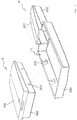
- eine räumliche explodierte Ansicht eines erfindungsgemäßen Gehäuses und einer erfindungsgemäßen zweiten Baueinheit des Wasserfahrzeugs aus
Fig. 1 , - Figur 3
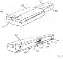
- eine ungeschnittene und eine geschnittene räumliche Ansicht eines erfindungsgemäßen Gehäuses und je einer dorthinein montierten erfindungsgemäßen ersten, zweiten und dritten Baueinheit des Wasserfahrzeugs aus
Fig. 1 und - Figur 4
- je eine geschnittene räumliche und vordere Ansicht von Querschnitten des Wasserfahrzeugs aus
Fig. 1 . - Die Figuren zeigen ein Wasserfahrzeug 2 und zu seinem Antrieb eine erste Baueinheit 4, eine zweite Baueinheit 6 und eine dritte Baueinheit 8 in einem Montagegehäuse 10.
- Das Wasserfahrzeug 2 ist ein Stehbrett nach Art eines Surfbretts, also eingerichtet für einen darauf stehenden Benutzer oder "Piloten" (nicht dargestellt). Das Wasserfahrzeug 2 ist zu seinem Antrieb mit einem Jetantrieb (nicht dargestellt) mit Elektromotorantrieb (nicht dargestellt) und mit einem elektrischen Energiespeicher (nicht dargestellt) für den Elektromotor ausgestattet. Der Jetantrieb und der Elektromotorantrieb sind in einer ersten Baueinheit 4 integriert und der Energiespeicher in einer zweiten Baueinheit 6. Beide Baueinheiten sind erfindungsgemäß eingerichtet, sich jeweils als integrale Baueinheit (insbesondere vormontiert und insgesamt) im Wasserfahrzeug 2 montieren und demontieren zu lassen.
- Die Baueinheiten 4, 6, 8 weisen (insbesondere zur Integration in die Konstruktion verschiedener Wasserfahrzeuge) ein gemeinsames Gehäuse 10 auf, in das sie (vorbereitet, eingerichtet, angepasst und passend) montierbar und demontierbar sind. Mit anderen Worten weisen die Baueinheiten 4, 6, 8 ein gemeinsames Gehäuse 10 auf, und sie sind vorbereitet, eingerichtet, angepasst und insbesondere in ihren Abmessungen und Verbindungselementen passend in das Gehäuse montierbar und daraus demontierbar. Das Gehäuse 10 ist dabei ein Außengerüst mit geschlossenen Wandungen, das die Baueinheiten 4, 6, 8 umgibt und nur in Bereichen 101, 102 einer Außenhaut des Fahrzeugs 2 Öffnungen 12 lässt.
- So bildet das Gehäuse 10 eine standardisierte Aufnahme für die austauschbare Energieversorgungseinheit 6 sowie die Antriebseinheit 4, die (mittels gleich gestalteter Gehäuse 10) in einer ganzen Wasserfahrzeug-Familie integriert werden können.
Fig. 1 zeigt exemplarisch den grundsätzlichen Aufbau und die Integration einer solchen Einheit in einem Wasserfahrzeug 2, hier ein Surfbrett 2. Dieses besteht aus einer äußeren Hülle 100, welche einen Styroporkern 600 als Schwimmkörper umhaust. Eine standardisierte Aufnahmeeinheit 10 bestehend aus einer Staufach-Akkubox-Aufnahme-Einheit (200) und Powerbox-Aufnahme-Einheit (Deckel 201 und Boden 202) und bietet Platz für das die zweite Baueinheit 6 (Batteriefach-Boden 300 und -Deckel 102), ein Staufach 8, 101 und die erste Baueinheit 4 (Powerbox-Deckel 400 und -Boden 401). Der Deckel 102 des Batteriefachs 6 ist dabei gleichzeitig ein Teil der Außenhülle oder Außenhaut 100 des Surfbretts 2 und schließt (montiert) bündig mit dieser ab. Außerdem beinhaltet der Deckel 102 einen Plug für Notstop 500 der Antriebskomponenten des Surfbretts 2. Die Powerbox 400, 401 beinhaltet die Antriebskomponenten (nicht dargestellt), wie den Jet, einen BLDC- bzw. PMSM-Motor, einen Fahrtenregler - sowie einen Schnittstellenstecker 302. Das Batteriefach 300, 102 beinhaltet einen Lithium-Ionen-Akku (nicht dargestellt), ein Batterie-Management-System (nicht dargestellt), einen Empfänger für eine Fernbedienung (beides nicht dargestellt), einen GPS-Empfänger sowie eine Sende- und Empfangsstation für die Kommunikation mit einer APP über Bluetooth-Schnittstelle (nicht dargestellt). Das ebenfalls in der Batterieaufnahme-Einheit 200 zu platzierende Staufach 8, 101 erfüllt neben seiner eigentlichen Funktion als Aufbewahrungsort auch eine Zusatzfunktion als Arretier- bzw. Klemmeinheit für das Batteriefach 6, 300, 102 und die dahinterliegende Powerbox 4, 400, 401. Auf dem Boden der Einheit 200 sind seitlich zwei Gleitschienen installiert, die sowohl ein leichtes Einsetzen der Akkubox ermöglichen als auch die Kräfte, die durch das Gewicht der Akkubox sowie des Fahrers auftreten, aufnehmen. Die Powerbox 4, 400, 401 wird zusätzlich durch Schraubverbindungen (nicht dargestellt) am Heck der Powerbox-Aufnahme-Einheit 201, 202 als auch im Bereich des Jet-Einlasses an der Unterseite des Bretts (nicht dargestellt) befestigt. Das Batteriefach 6, 300, 102 wird von oben durch die Öffnung 12 in der Hülle 100 in die Batterieaufnahme-Einheit 200 eingesetzt (Fig. 2 ) und durch ein spielarmes Führungsschienensystem 203 zu ihrer endgültigen Position in Richtung des Fahrzeughecks geführt. Die Verriegelung erfolgt durch Führungs- und Arretierungspins 303, welche die Befestigung des Batteriefachs (Akkubox) 6, 300,102 in der Vertikalen ermöglichen. In der Endposition wird ein als IP 68 zertifizierter Schnittstellenstecker 301, 302 geschlossen, wodurch eine Leistungs- und Kommunikationsübertragung zwischen relevanten Komponenten der Baueinheiten 4 und 6 ermöglicht werden. Der Stecker weist Führungspins (nicht dargestellt) auf, die die Zusammenführung der beiden Steckerelemente 301, 302 gewährleisten. Unter der Akkubox 6, 300,102 sind Gleitschienen (nicht dargestellt) installiert, die ein einfaches Schieben der Akkubox ermöglichen. Gleichzeitig nehmen die Gleitschienen das Gewicht der Akkubox (und des Fahrers) auf, so dass die Verriegelungspins 303 überwiegend der Führung ohne größere lastübertragende Funktion dienen. Die Arretierung erfolgt über das Einsetzen des Staufaches, wodurch gleichzeitig der erforderliche Anpressdruck sichergestellt wird. - Eine weitere Besonderheit der Konstruktion liegt in der Erzeugung eines Kühleffekts durch einen bewusst herbeigeführten Wasserstrom innerhalb des Fahrzeugrumpfs 2 (
Figur 1 ). Dies wird durch Ein- und Austrittsöffnungen erzielt, welche das Ein- und Ausströmen des Wassers in einen Hohlraum 700 zwischen dem Batteriefach 300 und Batteriefachaufnahme-Einheit 200 zulassen und somit eine Kühlung der Akku-Baueinheit 6 ermöglichen (Fig. 3 und4 ). Die Eintrittsöffnung ist aus einer Austrittsöffnung von Kühlwasser des Jetantriebs gespeist (305). Der Ablauf erfolgt in der Oberseite des Wasserfahrzeugs 2 und geht dort durch Fugenspalten zwischen dem Außenhautbereich 102, der von der dort eingesetzten zweiten Baueinheit 6, 300, 102 gebildet wird, und der im Übrigen umgebenden Außenhaut 100 des Wasserfahrzeugs 2. Der Hohlraum 700 ist dann für seine Kühlfunktionalität neben der Energiespeicher-Baueinheit 6, 300, 102 im Gehäuse 10 so angeordnet, dass Wärme aus dieser Baueinheit mit dem Kühlwasser im Hohlraum 700 ausgetauscht und mit dem Kühlwasser aus dem Hohlraum 700 abgeführt werden kann. -
- Wasserfahrzeug 2
- Surfbrett 2
- erste Baueinheit 4
- zweite Baueinheit 6
- dritte Baueinheit 8
- Staufach 8
- Antriebseinheit 4
- Gehäuse 10
- Aufnahmeeinheit 10
- Öffnungen 12
- IP 68
- äußeren Hülle 100
- Batteriefach-Deckel 102
- Batterieaufnahme-Einheit 200
- Deckel 201
- Boden 202
- Batteriefach-Boden 300
- Batteriefach 300
- Steckerelemente 301, 302
- Führungs- und Arretierungspins 303
- Verriegelungspins 303
- Powerbox 400
- Antriebskomponenten 401
- Notstop 500
- Styroporkern 600
- Hohlraum 700
Claims (11)
- Wasserfahrzeug (2) mit Jetantrieb mit Elektromotorantrieb und mit einem elektrischen Energiespeicher für den Elektromotor, dadurch gekennzeichnet, dass der Energiespeicher in einer Baueinheit (4, 6, 8) integriert ist, die eingerichtet ist, sich als integrale Baueinheit im Wasserfahrzeug (2) montieren und demontieren zu lassen.
- Wasserfahrzeug (2) nach dem vorhergehenden Anspruch, dadurch gekennzeichnet, dass die Baueinheit (4, 6, 8) in ein Gehäuse (10) so montierbar ist, dass in dem Gehäuse (10) ein unausgefüllter Kühlwasser-Hohlraum (700) verbleibt, der einen Zulauf für Kühlwasser sowie einen Ablauf für das Kühlwasser aufweist und dass der Hohlraum (700) neben der Baueinheit (4, 6, 8) im Gehäuse (10) so angeordnet ist, dass Wärme aus der zweiten Baueinheit (4, 6, 8) mit dem Kühlwasser im Hohlraum (700) ausgetauscht werden kann.
- Wasserfahrzeug (2) nach dem vorhergehenden Anspruch, dadurch gekennzeichnet, dass der Jetantrieb und der Elektromotorantrieb in einer ersten Baueinheit (4) integriert sind und der Energiespeicher in einer zweiten Baueinheit (6), die beide eingerichtet sind, sich jeweils als integrale Baueinheit im Wasserfahrzeug (2) montieren und demontieren zu lassen.
- Wasserfahrzeug (2) nach dem vorhergehenden Anspruch, dadurch gekennzeichnet, dass die Montage der zweiten Baueinheit (6) die Demontage der ersten Baueinheit (4) versperrt und/oder dass die Demontage der zweiten Baueinheit (6) die Demontage der ersten Baueinheit (4) freigibt.
- Wasserfahrzeug (2) nach einem der beiden vorhergehenden Ansprüche, dadurch gekennzeichnet, dass ein herausnehmbares Staufach (8) sich als dritte integrale Baueinheit (8) im Wasserfahrzeug (2) montieren lässt.
- Wasserfahrzeug (2) nach dem vorhergehenden Anspruch, dadurch gekennzeichnet, dass die Montage der dritten Baueinheit (8) die Demontage der zweiten Baueinheit (4) versperrt und/oder die Demontage der dritten Baueinheit (8) die Demontage der zweiten Baueinheit (6) freigibt.
- Wasserfahrzeug (2) nach einem der vorhergehenden Ansprüche, dadurch gekennzeichnet, dass mindestens die zweite Baueinheit (6) einen Bereich einer Außenhaut des Wasserfahrzeugs (2) aufweist.
- Wasserfahrzeug (2) nach einem der vorhergehenden Ansprüche, dadurch gekennzeichnet, dass das Wasserfahrzeug (2) eingerichtet ist, einen Piloten des Wasserfahrzeugs (2) aufzunehmen, und dass in dem Bereich der Außenhaut und in Reichweite des Piloten des Wasserfahrzeugs (2) eine Antriebs-Notaus-Betätigungsvorrichtung angeordnet ist.
- Wasserfahrzeug (2) nach einem der vorhergehenden Ansprüche, dadurch gekennzeichnet, dass mindestens die zweite Baueinheit (6) ein Gehäuse (10) aufweisen, in das sie montierbar und demontierbar sind.
- Wasserfahrzeug (2) nach einem der vorhergehenden Ansprüche, dadurch gekennzeichnet, dass der Kühlwasser-Hohlraum (700) einen Zulauf für Kühlwasser aus einer Austrittsöffnung von Kühlwasser des Jetantriebs und/oder aus einer Eintrittsöffnung aufweist, die so in einer Außenhaut des Wasserfahrzeugs (2) angeordnet ist, dass sie bei dessen Fahrt vom Wasser angeströmt ist und Wasser in den Hohlraum (700) einlässt, sowie einen Ablauf für das Kühlwasser aus einer Austrittsöffnung, die so in einer Außenhaut des Wasserfahrzeugs (2) angeordnet ist, dass sie bei dessen Fahrt das Kühlwasser aus dem Hohlraum (700) entlässt, und dass der Hohlraum (700) neben der zweiten Baueinheit (6) im Gehäuse (10) so angeordnet ist, dass Wärme aus der zweiten Baueinheit (6) mit dem Kühlwasser im Hohlraum (700) ausgetauscht werden kann.
- System von Baueinheiten (4, 6, 8) nach einem der vorhergehenden Ansprüche für ein Wasserfahrzeug (2) nach einem der vorhergehenden Ansprüche.
Applications Claiming Priority (1)
| Application Number | Priority Date | Filing Date | Title |
|---|---|---|---|
| DE102018120094.3A DE102018120094A1 (de) | 2018-08-17 | 2018-08-17 | Wasserfahrzeug mit elektromotorischem Jetantrieb |
Publications (3)
| Publication Number | Publication Date |
|---|---|
| EP3611092A1 true EP3611092A1 (de) | 2020-02-19 |
| EP3611092B1 EP3611092B1 (de) | 2024-01-03 |
| EP3611092C0 EP3611092C0 (de) | 2024-01-03 |
Family
ID=67659187
Family Applications (1)
| Application Number | Title | Priority Date | Filing Date |
|---|---|---|---|
| EP19192051.1A Active EP3611092B1 (de) | 2018-08-17 | 2019-08-16 | Wasserfahrzeug mit elektromotorischem jetantrieb |
Country Status (2)
| Country | Link |
|---|---|
| EP (1) | EP3611092B1 (de) |
| DE (1) | DE102018120094A1 (de) |
Cited By (6)
| Publication number | Priority date | Publication date | Assignee | Title |
|---|---|---|---|---|
| WO2021190941A1 (de) * | 2020-03-25 | 2021-09-30 | 2K Beteiligungen UG (haftungsbeschränkt) | Steuerung eines wasserfahrzeugs |
| US11383797B2 (en) | 2017-12-27 | 2022-07-12 | Ride Awake Ab | Electric motorized watercraft and driveline system |
| EP4035986A1 (de) * | 2021-01-27 | 2022-08-03 | Ewake Germany GmbH | Wake- oder surfboard mit einem elektrischen antrieb und einem internen akku |
| CN114954811A (zh) * | 2022-06-22 | 2022-08-30 | 江苏有亩田科技有限公司 | 一种水上滑行器 |
| US11608144B2 (en) | 2020-01-03 | 2023-03-21 | Ride Awake Ab | Motorized watercraft |
| USD995678S1 (en) | 2020-01-03 | 2023-08-15 | Ride Awake Ab | Electronically propelled surfboard |
Families Citing this family (1)
| Publication number | Priority date | Publication date | Assignee | Title |
|---|---|---|---|---|
| DE102023130680A1 (de) * | 2023-11-06 | 2025-05-08 | Torqeedo Gmbh | Verbindungssystem für einen Außenbordmotor |
Citations (7)
| Publication number | Priority date | Publication date | Assignee | Title |
|---|---|---|---|---|
| CN2295506Y (zh) * | 1997-05-20 | 1998-10-28 | 孙正军 | 电动游泳板 |
| US20050181686A1 (en) * | 2000-02-26 | 2005-08-18 | Andrea Grimmeisen | Motorized watercraft |
| US20110201238A1 (en) * | 2010-02-13 | 2011-08-18 | Wavedrive Systems, Inc. | Electric Powered Surfboard Propulsion and Control Systems |
| US20150064995A1 (en) * | 2012-08-29 | 2015-03-05 | Inventive Design Group, Inc. | Weight steerable self-propelled personal watercraft |
| US20150307166A1 (en) * | 2014-04-24 | 2015-10-29 | Wesley Zhou | Paddle Board With Internal Propulsion Drive |
| US20150367922A1 (en) * | 2013-01-18 | 2015-12-24 | Cayago Gmbh | Watercraft comprising a redundant energy accumulator |
| WO2019129687A1 (en) * | 2017-12-27 | 2019-07-04 | Ride Awake Ab | Electric motorised watercraft and driveline system |
Family Cites Families (3)
| Publication number | Priority date | Publication date | Assignee | Title |
|---|---|---|---|---|
| EP1704085A4 (de) * | 2003-12-16 | 2007-07-04 | Concept To Reality Pty Ltd | Antriebsvorrichtung für wasserfahrzeuge |
| US7930985B2 (en) * | 2008-01-02 | 2011-04-26 | Walworth Christopher J | Sports board |
| CN208484799U (zh) * | 2018-05-14 | 2019-02-12 | 田瑜 | 冲浪设备 |
-
2018
- 2018-08-17 DE DE102018120094.3A patent/DE102018120094A1/de not_active Withdrawn
-
2019
- 2019-08-16 EP EP19192051.1A patent/EP3611092B1/de active Active
Patent Citations (7)
| Publication number | Priority date | Publication date | Assignee | Title |
|---|---|---|---|---|
| CN2295506Y (zh) * | 1997-05-20 | 1998-10-28 | 孙正军 | 电动游泳板 |
| US20050181686A1 (en) * | 2000-02-26 | 2005-08-18 | Andrea Grimmeisen | Motorized watercraft |
| US20110201238A1 (en) * | 2010-02-13 | 2011-08-18 | Wavedrive Systems, Inc. | Electric Powered Surfboard Propulsion and Control Systems |
| US20150064995A1 (en) * | 2012-08-29 | 2015-03-05 | Inventive Design Group, Inc. | Weight steerable self-propelled personal watercraft |
| US20150367922A1 (en) * | 2013-01-18 | 2015-12-24 | Cayago Gmbh | Watercraft comprising a redundant energy accumulator |
| US20150307166A1 (en) * | 2014-04-24 | 2015-10-29 | Wesley Zhou | Paddle Board With Internal Propulsion Drive |
| WO2019129687A1 (en) * | 2017-12-27 | 2019-07-04 | Ride Awake Ab | Electric motorised watercraft and driveline system |
Cited By (10)
| Publication number | Priority date | Publication date | Assignee | Title |
|---|---|---|---|---|
| US11383797B2 (en) | 2017-12-27 | 2022-07-12 | Ride Awake Ab | Electric motorized watercraft and driveline system |
| EP4043333A1 (de) | 2017-12-27 | 2022-08-17 | Ride Awake AB | Elektrisches motorwasserfahrzeug und antriebssystem |
| EP3732098B1 (de) * | 2017-12-27 | 2023-08-02 | Ride Awake AB | Elektrisches motorwasserfahrzeug und antriebssystem |
| US11780538B2 (en) | 2017-12-27 | 2023-10-10 | Ride Awake Ab | Electric motorised watercraft and driveline system |
| US11608144B2 (en) | 2020-01-03 | 2023-03-21 | Ride Awake Ab | Motorized watercraft |
| USD995678S1 (en) | 2020-01-03 | 2023-08-15 | Ride Awake Ab | Electronically propelled surfboard |
| WO2021190941A1 (de) * | 2020-03-25 | 2021-09-30 | 2K Beteiligungen UG (haftungsbeschränkt) | Steuerung eines wasserfahrzeugs |
| US20230019805A1 (en) * | 2020-03-25 | 2023-01-19 | 2K Beteiligungen UG (haftungsbeschraunkt) | Control of a watercraft |
| EP4035986A1 (de) * | 2021-01-27 | 2022-08-03 | Ewake Germany GmbH | Wake- oder surfboard mit einem elektrischen antrieb und einem internen akku |
| CN114954811A (zh) * | 2022-06-22 | 2022-08-30 | 江苏有亩田科技有限公司 | 一种水上滑行器 |
Also Published As
| Publication number | Publication date |
|---|---|
| DE102018120094A1 (de) | 2020-02-20 |
| EP3611092B1 (de) | 2024-01-03 |
| EP3611092C0 (de) | 2024-01-03 |
Similar Documents
| Publication | Publication Date | Title |
|---|---|---|
| EP3611092B1 (de) | Wasserfahrzeug mit elektromotorischem jetantrieb | |
| DE202018104741U1 (de) | Wasserfahrzeug mit elektromotorischem Jetantrieb | |
| DE60302308T2 (de) | Hochspannungsvorrichtungsgehäuse und -verbinder | |
| EP2456637B1 (de) | Wechselakku-kreislauf-system für elektro-kraftfahrzeuge | |
| EP3354555B1 (de) | Wasserfahrzeug mit flutungsraum | |
| DE102012218817B4 (de) | Integrierter struktureller und elektrischer verbinder | |
| DE102017130946A1 (de) | Surfboard mit wechselakkumulator | |
| EP1537017B1 (de) | Ausrüstungssystem-schiffstyp "fregatte" | |
| DE2558456C2 (de) | Energiespeicher für Elektrofahrzeuge | |
| DE202017107818U1 (de) | Surfboard mit Wechselakkumulator | |
| DE102020103126A1 (de) | Kühlplatte für ein wiederaufladbares energiespeichersystem | |
| DE102014008480A1 (de) | Fahrzeug mit einem Energiespeicher | |
| DE102013100543B4 (de) | Wasserfahrzeug mit redundantem Energiespeicher | |
| DE102017119466A1 (de) | Vorrichtung zur Speicherung elektrischer Energie für ein Kraftfahrzeug | |
| DE4411844A1 (de) | Stromzufuhreinheit für Elektrofahrzeuge | |
| DE112015001742T5 (de) | Elektrisches Kraftwerkzeug | |
| EP3570945A1 (de) | Schwimm- und tauchhilfe mit einer kamera | |
| DE10324170A1 (de) | Elektrofahrzeugsystem | |
| DE102018129501A1 (de) | Wasserfahrzeug mit einer Energieversorgungseinheit | |
| DE102009048573A1 (de) | Kraftfahrzeug, insbesondere Dreirad | |
| DE102018213240A1 (de) | Pistenraupe mit einem Kettenlaufwerk | |
| DE102017211370B4 (de) | Verfahren zum Betreiben eines Luftfahrzeugs sowie Luftfahrzeug | |
| DE102022131064A1 (de) | Kreisförmige konfiguration von batteriezellen für flugzeuge | |
| DE102007056413A1 (de) | Mechanismus zum Verspannen wenigstens zweier Gehäuseteile eines Wasserfortbewegungsmittels, Wasserfortbewegungsmittel zum Transportieren eines Tauchers und Energieversorgung für ein Wasserfortbewegungsmittel | |
| DE202007019718U1 (de) | Unterwasserfahrzeug für Taucher |
Legal Events
| Date | Code | Title | Description |
|---|---|---|---|
| PUAI | Public reference made under article 153(3) epc to a published international application that has entered the european phase |
Free format text: ORIGINAL CODE: 0009012 |
|
| STAA | Information on the status of an ep patent application or granted ep patent |
Free format text: STATUS: THE APPLICATION HAS BEEN PUBLISHED |
|
| AK | Designated contracting states |
Kind code of ref document: A1 Designated state(s): AL AT BE BG CH CY CZ DE DK EE ES FI FR GB GR HR HU IE IS IT LI LT LU LV MC MK MT NL NO PL PT RO RS SE SI SK SM TR |
|
| AX | Request for extension of the european patent |
Extension state: BA ME |
|
| STAA | Information on the status of an ep patent application or granted ep patent |
Free format text: STATUS: REQUEST FOR EXAMINATION WAS MADE |
|
| 17P | Request for examination filed |
Effective date: 20200818 |
|
| RBV | Designated contracting states (corrected) |
Designated state(s): AL AT BE BG CH CY CZ DE DK EE ES FI FR GB GR HR HU IE IS IT LI LT LU LV MC MK MT NL NO PL PT RO RS SE SI SK SM TR |
|
| STAA | Information on the status of an ep patent application or granted ep patent |
Free format text: STATUS: EXAMINATION IS IN PROGRESS |
|
| 17Q | First examination report despatched |
Effective date: 20201118 |
|
| RAP3 | Party data changed (applicant data changed or rights of an application transferred) |
Owner name: AVEO TECHNOLOGIES GMBH |
|
| REG | Reference to a national code |
Ref country code: DE Ref legal event code: R079 Ref document number: 502019010264 Country of ref document: DE Free format text: PREVIOUS MAIN CLASS: B63H0011020000 Ipc: B63B0032100000 |
|
| RIC1 | Information provided on ipc code assigned before grant |
Ipc: B63B 32/10 20200101AFI20230718BHEP |
|
| GRAP | Despatch of communication of intention to grant a patent |
Free format text: ORIGINAL CODE: EPIDOSNIGR1 |
|
| STAA | Information on the status of an ep patent application or granted ep patent |
Free format text: STATUS: GRANT OF PATENT IS INTENDED |
|
| INTG | Intention to grant announced |
Effective date: 20230905 |
|
| GRAS | Grant fee paid |
Free format text: ORIGINAL CODE: EPIDOSNIGR3 |
|
| GRAA | (expected) grant |
Free format text: ORIGINAL CODE: 0009210 |
|
| STAA | Information on the status of an ep patent application or granted ep patent |
Free format text: STATUS: THE PATENT HAS BEEN GRANTED |
|
| AK | Designated contracting states |
Kind code of ref document: B1 Designated state(s): AL AT BE BG CH CY CZ DE DK EE ES FI FR GB GR HR HU IE IS IT LI LT LU LV MC MK MT NL NO PL PT RO RS SE SI SK SM TR |
|
| REG | Reference to a national code |
Ref country code: GB Ref legal event code: FG4D Free format text: NOT ENGLISH |
|
| REG | Reference to a national code |
Ref country code: DE Ref legal event code: R096 Ref document number: 502019010264 Country of ref document: DE |
|
| REG | Reference to a national code |
Ref country code: CH Ref legal event code: EP |
|
| REG | Reference to a national code |
Ref country code: IE Ref legal event code: FG4D Free format text: LANGUAGE OF EP DOCUMENT: GERMAN |
|
| U01 | Request for unitary effect filed |
Effective date: 20240202 |
|
| RAP4 | Party data changed (patent owner data changed or rights of a patent transferred) |
Owner name: AVEO TECHNOLOGIES GMBH |
|
| U07 | Unitary effect registered |
Designated state(s): AT BE BG DE DK EE FI FR IT LT LU LV MT NL PT SE SI Effective date: 20240305 |
|
| REG | Reference to a national code |
Ref country code: LT Ref legal event code: MG9D |
|
| PG25 | Lapsed in a contracting state [announced via postgrant information from national office to epo] |
Ref country code: ES Free format text: LAPSE BECAUSE OF FAILURE TO SUBMIT A TRANSLATION OF THE DESCRIPTION OR TO PAY THE FEE WITHIN THE PRESCRIBED TIME-LIMIT Effective date: 20240103 |
|
| PG25 | Lapsed in a contracting state [announced via postgrant information from national office to epo] |
Ref country code: ES Free format text: LAPSE BECAUSE OF FAILURE TO SUBMIT A TRANSLATION OF THE DESCRIPTION OR TO PAY THE FEE WITHIN THE PRESCRIBED TIME-LIMIT Effective date: 20240103 |
|
| PG25 | Lapsed in a contracting state [announced via postgrant information from national office to epo] |
Ref country code: IS Free format text: LAPSE BECAUSE OF FAILURE TO SUBMIT A TRANSLATION OF THE DESCRIPTION OR TO PAY THE FEE WITHIN THE PRESCRIBED TIME-LIMIT Effective date: 20240503 |
|
| PG25 | Lapsed in a contracting state [announced via postgrant information from national office to epo] |
Ref country code: GR Free format text: LAPSE BECAUSE OF FAILURE TO SUBMIT A TRANSLATION OF THE DESCRIPTION OR TO PAY THE FEE WITHIN THE PRESCRIBED TIME-LIMIT Effective date: 20240404 |
|
| PG25 | Lapsed in a contracting state [announced via postgrant information from national office to epo] |
Ref country code: RS Free format text: LAPSE BECAUSE OF FAILURE TO SUBMIT A TRANSLATION OF THE DESCRIPTION OR TO PAY THE FEE WITHIN THE PRESCRIBED TIME-LIMIT Effective date: 20240403 Ref country code: HR Free format text: LAPSE BECAUSE OF FAILURE TO SUBMIT A TRANSLATION OF THE DESCRIPTION OR TO PAY THE FEE WITHIN THE PRESCRIBED TIME-LIMIT Effective date: 20240103 |
|
| PG25 | Lapsed in a contracting state [announced via postgrant information from national office to epo] |
Ref country code: CZ Free format text: LAPSE BECAUSE OF FAILURE TO SUBMIT A TRANSLATION OF THE DESCRIPTION OR TO PAY THE FEE WITHIN THE PRESCRIBED TIME-LIMIT Effective date: 20240103 |
|
| PG25 | Lapsed in a contracting state [announced via postgrant information from national office to epo] |
Ref country code: RS Free format text: LAPSE BECAUSE OF FAILURE TO SUBMIT A TRANSLATION OF THE DESCRIPTION OR TO PAY THE FEE WITHIN THE PRESCRIBED TIME-LIMIT Effective date: 20240403 Ref country code: NO Free format text: LAPSE BECAUSE OF FAILURE TO SUBMIT A TRANSLATION OF THE DESCRIPTION OR TO PAY THE FEE WITHIN THE PRESCRIBED TIME-LIMIT Effective date: 20240403 Ref country code: IS Free format text: LAPSE BECAUSE OF FAILURE TO SUBMIT A TRANSLATION OF THE DESCRIPTION OR TO PAY THE FEE WITHIN THE PRESCRIBED TIME-LIMIT Effective date: 20240503 Ref country code: HR Free format text: LAPSE BECAUSE OF FAILURE TO SUBMIT A TRANSLATION OF THE DESCRIPTION OR TO PAY THE FEE WITHIN THE PRESCRIBED TIME-LIMIT Effective date: 20240103 Ref country code: GR Free format text: LAPSE BECAUSE OF FAILURE TO SUBMIT A TRANSLATION OF THE DESCRIPTION OR TO PAY THE FEE WITHIN THE PRESCRIBED TIME-LIMIT Effective date: 20240404 Ref country code: CZ Free format text: LAPSE BECAUSE OF FAILURE TO SUBMIT A TRANSLATION OF THE DESCRIPTION OR TO PAY THE FEE WITHIN THE PRESCRIBED TIME-LIMIT Effective date: 20240103 |
|
| PG25 | Lapsed in a contracting state [announced via postgrant information from national office to epo] |
Ref country code: PL Free format text: LAPSE BECAUSE OF FAILURE TO SUBMIT A TRANSLATION OF THE DESCRIPTION OR TO PAY THE FEE WITHIN THE PRESCRIBED TIME-LIMIT Effective date: 20240103 |
|
| PG25 | Lapsed in a contracting state [announced via postgrant information from national office to epo] |
Ref country code: PL Free format text: LAPSE BECAUSE OF FAILURE TO SUBMIT A TRANSLATION OF THE DESCRIPTION OR TO PAY THE FEE WITHIN THE PRESCRIBED TIME-LIMIT Effective date: 20240103 |
|
| REG | Reference to a national code |
Ref country code: DE Ref legal event code: R097 Ref document number: 502019010264 Country of ref document: DE |
|
| U20 | Renewal fee for the european patent with unitary effect paid |
Year of fee payment: 6 Effective date: 20240902 |
|
| PG25 | Lapsed in a contracting state [announced via postgrant information from national office to epo] |
Ref country code: SM Free format text: LAPSE BECAUSE OF FAILURE TO SUBMIT A TRANSLATION OF THE DESCRIPTION OR TO PAY THE FEE WITHIN THE PRESCRIBED TIME-LIMIT Effective date: 20240103 |
|
| PG25 | Lapsed in a contracting state [announced via postgrant information from national office to epo] |
Ref country code: SK Free format text: LAPSE BECAUSE OF FAILURE TO SUBMIT A TRANSLATION OF THE DESCRIPTION OR TO PAY THE FEE WITHIN THE PRESCRIBED TIME-LIMIT Effective date: 20240103 |
|
| PG25 | Lapsed in a contracting state [announced via postgrant information from national office to epo] |
Ref country code: SM Free format text: LAPSE BECAUSE OF FAILURE TO SUBMIT A TRANSLATION OF THE DESCRIPTION OR TO PAY THE FEE WITHIN THE PRESCRIBED TIME-LIMIT Effective date: 20240103 Ref country code: SK Free format text: LAPSE BECAUSE OF FAILURE TO SUBMIT A TRANSLATION OF THE DESCRIPTION OR TO PAY THE FEE WITHIN THE PRESCRIBED TIME-LIMIT Effective date: 20240103 Ref country code: RO Free format text: LAPSE BECAUSE OF FAILURE TO SUBMIT A TRANSLATION OF THE DESCRIPTION OR TO PAY THE FEE WITHIN THE PRESCRIBED TIME-LIMIT Effective date: 20240103 |
|
| PLBE | No opposition filed within time limit |
Free format text: ORIGINAL CODE: 0009261 |
|
| STAA | Information on the status of an ep patent application or granted ep patent |
Free format text: STATUS: NO OPPOSITION FILED WITHIN TIME LIMIT |
|
| 26N | No opposition filed |
Effective date: 20241007 |
|
| REG | Reference to a national code |
Ref country code: CH Ref legal event code: PL |
|
| GBPC | Gb: european patent ceased through non-payment of renewal fee |
Effective date: 20240816 |
|
| PG25 | Lapsed in a contracting state [announced via postgrant information from national office to epo] |
Ref country code: CH Free format text: LAPSE BECAUSE OF NON-PAYMENT OF DUE FEES Effective date: 20240831 Ref country code: MC Free format text: LAPSE BECAUSE OF FAILURE TO SUBMIT A TRANSLATION OF THE DESCRIPTION OR TO PAY THE FEE WITHIN THE PRESCRIBED TIME-LIMIT Effective date: 20240103 |
|
| PG25 | Lapsed in a contracting state [announced via postgrant information from national office to epo] |
Ref country code: GB Free format text: LAPSE BECAUSE OF NON-PAYMENT OF DUE FEES Effective date: 20240816 |
|
| PG25 | Lapsed in a contracting state [announced via postgrant information from national office to epo] |
Ref country code: IE Free format text: LAPSE BECAUSE OF NON-PAYMENT OF DUE FEES Effective date: 20240816 |
|
| PG25 | Lapsed in a contracting state [announced via postgrant information from national office to epo] |
Ref country code: CY Free format text: LAPSE BECAUSE OF FAILURE TO SUBMIT A TRANSLATION OF THE DESCRIPTION OR TO PAY THE FEE WITHIN THE PRESCRIBED TIME-LIMIT; INVALID AB INITIO Effective date: 20190816 |
|
| PG25 | Lapsed in a contracting state [announced via postgrant information from national office to epo] |
Ref country code: HU Free format text: LAPSE BECAUSE OF FAILURE TO SUBMIT A TRANSLATION OF THE DESCRIPTION OR TO PAY THE FEE WITHIN THE PRESCRIBED TIME-LIMIT; INVALID AB INITIO Effective date: 20190816 |
|
| U90 | Renewal fees not paid: noting of loss of rights |
Free format text: RENEWAL FEE NOT PAID FOR YEAR 07 Effective date: 20260323 |