EP3611046A1 - Hybrid electrodynamic levitation system - Google Patents
Hybrid electrodynamic levitation system Download PDFInfo
- Publication number
- EP3611046A1 EP3611046A1 EP19188709.0A EP19188709A EP3611046A1 EP 3611046 A1 EP3611046 A1 EP 3611046A1 EP 19188709 A EP19188709 A EP 19188709A EP 3611046 A1 EP3611046 A1 EP 3611046A1
- Authority
- EP
- European Patent Office
- Prior art keywords
- vehicle
- rail
- track
- magnetic field
- lift
- Prior art date
- Legal status (The legal status is an assumption and is not a legal conclusion. Google has not performed a legal analysis and makes no representation as to the accuracy of the status listed.)
- Granted
Links
- 238000005339 levitation Methods 0.000 title abstract description 29
- 230000005520 electrodynamics Effects 0.000 title abstract description 10
- 230000005291 magnetic effect Effects 0.000 claims description 66
- 239000004020 conductor Substances 0.000 claims description 45
- 239000002887 superconductor Substances 0.000 claims description 33
- 230000004044 response Effects 0.000 claims description 20
- 239000000725 suspension Substances 0.000 claims description 12
- 230000001133 acceleration Effects 0.000 claims description 10
- 238000000034 method Methods 0.000 claims description 9
- 239000013078 crystal Substances 0.000 claims description 7
- 239000007787 solid Substances 0.000 claims description 6
- 239000012212 insulator Substances 0.000 claims description 5
- 239000003302 ferromagnetic material Substances 0.000 claims description 4
- 239000000463 material Substances 0.000 description 11
- IJGRMHOSHXDMSA-UHFFFAOYSA-N Atomic nitrogen Chemical compound N#N IJGRMHOSHXDMSA-UHFFFAOYSA-N 0.000 description 10
- 238000004590 computer program Methods 0.000 description 6
- 230000007704 transition Effects 0.000 description 6
- 230000005294 ferromagnetic effect Effects 0.000 description 5
- 239000007788 liquid Substances 0.000 description 5
- 229910052757 nitrogen Inorganic materials 0.000 description 5
- XEEYBQQBJWHFJM-UHFFFAOYSA-N Iron Chemical compound [Fe] XEEYBQQBJWHFJM-UHFFFAOYSA-N 0.000 description 4
- 238000001816 cooling Methods 0.000 description 4
- 230000004907 flux Effects 0.000 description 4
- XAGFODPZIPBFFR-UHFFFAOYSA-N aluminium Chemical compound [Al] XAGFODPZIPBFFR-UHFFFAOYSA-N 0.000 description 3
- 229910052782 aluminium Inorganic materials 0.000 description 3
- 230000008859 change Effects 0.000 description 3
- 238000004519 manufacturing process Methods 0.000 description 3
- 229910000521 B alloy Inorganic materials 0.000 description 2
- ZOXJGFHDIHLPTG-UHFFFAOYSA-N Boron Chemical compound [B] ZOXJGFHDIHLPTG-UHFFFAOYSA-N 0.000 description 2
- 229910000640 Fe alloy Inorganic materials 0.000 description 2
- 229910000583 Nd alloy Inorganic materials 0.000 description 2
- 238000003491 array Methods 0.000 description 2
- 239000002826 coolant Substances 0.000 description 2
- 230000003247 decreasing effect Effects 0.000 description 2
- 238000005516 engineering process Methods 0.000 description 2
- 230000006870 function Effects 0.000 description 2
- 230000004048 modification Effects 0.000 description 2
- 238000012986 modification Methods 0.000 description 2
- 238000012545 processing Methods 0.000 description 2
- 238000005057 refrigeration Methods 0.000 description 2
- 238000012546 transfer Methods 0.000 description 2
- 229910001094 6061 aluminium alloy Inorganic materials 0.000 description 1
- 229910000831 Steel Inorganic materials 0.000 description 1
- 238000013459 approach Methods 0.000 description 1
- 230000003190 augmentative effect Effects 0.000 description 1
- 230000008901 benefit Effects 0.000 description 1
- 238000009835 boiling Methods 0.000 description 1
- 230000008878 coupling Effects 0.000 description 1
- 238000010168 coupling process Methods 0.000 description 1
- 238000005859 coupling reaction Methods 0.000 description 1
- 230000007423 decrease Effects 0.000 description 1
- 238000005265 energy consumption Methods 0.000 description 1
- 230000006872 improvement Effects 0.000 description 1
- 238000009413 insulation Methods 0.000 description 1
- 230000003993 interaction Effects 0.000 description 1
- 239000012811 non-conductive material Substances 0.000 description 1
- 238000005457 optimization Methods 0.000 description 1
- 230000002093 peripheral effect Effects 0.000 description 1
- 239000002985 plastic film Substances 0.000 description 1
- 229910052761 rare earth metal Inorganic materials 0.000 description 1
- 150000002910 rare earth metals Chemical class 0.000 description 1
- 239000003507 refrigerant Substances 0.000 description 1
- 238000005096 rolling process Methods 0.000 description 1
- 238000004513 sizing Methods 0.000 description 1
- 239000010935 stainless steel Substances 0.000 description 1
- 229910001220 stainless steel Inorganic materials 0.000 description 1
- 239000010959 steel Substances 0.000 description 1
- 230000000007 visual effect Effects 0.000 description 1
Images


Classifications
-
- B—PERFORMING OPERATIONS; TRANSPORTING
- B60—VEHICLES IN GENERAL
- B60L—PROPULSION OF ELECTRICALLY-PROPELLED VEHICLES; SUPPLYING ELECTRIC POWER FOR AUXILIARY EQUIPMENT OF ELECTRICALLY-PROPELLED VEHICLES; ELECTRODYNAMIC BRAKE SYSTEMS FOR VEHICLES IN GENERAL; MAGNETIC SUSPENSION OR LEVITATION FOR VEHICLES; MONITORING OPERATING VARIABLES OF ELECTRICALLY-PROPELLED VEHICLES; ELECTRIC SAFETY DEVICES FOR ELECTRICALLY-PROPELLED VEHICLES
- B60L13/00—Electric propulsion for monorail vehicles, suspension vehicles or rack railways; Magnetic suspension or levitation for vehicles
- B60L13/10—Combination of electric propulsion and magnetic suspension or levitation
-
- B—PERFORMING OPERATIONS; TRANSPORTING
- B60—VEHICLES IN GENERAL
- B60L—PROPULSION OF ELECTRICALLY-PROPELLED VEHICLES; SUPPLYING ELECTRIC POWER FOR AUXILIARY EQUIPMENT OF ELECTRICALLY-PROPELLED VEHICLES; ELECTRODYNAMIC BRAKE SYSTEMS FOR VEHICLES IN GENERAL; MAGNETIC SUSPENSION OR LEVITATION FOR VEHICLES; MONITORING OPERATING VARIABLES OF ELECTRICALLY-PROPELLED VEHICLES; ELECTRIC SAFETY DEVICES FOR ELECTRICALLY-PROPELLED VEHICLES
- B60L13/00—Electric propulsion for monorail vehicles, suspension vehicles or rack railways; Magnetic suspension or levitation for vehicles
- B60L13/04—Magnetic suspension or levitation for vehicles
- B60L13/06—Means to sense or control vehicle position or attitude with respect to railway
-
- B—PERFORMING OPERATIONS; TRANSPORTING
- B60—VEHICLES IN GENERAL
- B60L—PROPULSION OF ELECTRICALLY-PROPELLED VEHICLES; SUPPLYING ELECTRIC POWER FOR AUXILIARY EQUIPMENT OF ELECTRICALLY-PROPELLED VEHICLES; ELECTRODYNAMIC BRAKE SYSTEMS FOR VEHICLES IN GENERAL; MAGNETIC SUSPENSION OR LEVITATION FOR VEHICLES; MONITORING OPERATING VARIABLES OF ELECTRICALLY-PROPELLED VEHICLES; ELECTRIC SAFETY DEVICES FOR ELECTRICALLY-PROPELLED VEHICLES
- B60L15/00—Methods, circuits, or devices for controlling the traction-motor speed of electrically-propelled vehicles
- B60L15/002—Methods, circuits, or devices for controlling the traction-motor speed of electrically-propelled vehicles for control of propulsion for monorail vehicles, suspension vehicles or rack railways; for control of magnetic suspension or levitation for vehicles for propulsion purposes
-
- B—PERFORMING OPERATIONS; TRANSPORTING
- B60—VEHICLES IN GENERAL
- B60L—PROPULSION OF ELECTRICALLY-PROPELLED VEHICLES; SUPPLYING ELECTRIC POWER FOR AUXILIARY EQUIPMENT OF ELECTRICALLY-PROPELLED VEHICLES; ELECTRODYNAMIC BRAKE SYSTEMS FOR VEHICLES IN GENERAL; MAGNETIC SUSPENSION OR LEVITATION FOR VEHICLES; MONITORING OPERATING VARIABLES OF ELECTRICALLY-PROPELLED VEHICLES; ELECTRIC SAFETY DEVICES FOR ELECTRICALLY-PROPELLED VEHICLES
- B60L15/00—Methods, circuits, or devices for controlling the traction-motor speed of electrically-propelled vehicles
- B60L15/20—Methods, circuits, or devices for controlling the traction-motor speed of electrically-propelled vehicles for control of the vehicle or its driving motor to achieve a desired performance, e.g. speed, torque, programmed variation of speed
-
- B—PERFORMING OPERATIONS; TRANSPORTING
- B61—RAILWAYS
- B61B—RAILWAY SYSTEMS; EQUIPMENT THEREFOR NOT OTHERWISE PROVIDED FOR
- B61B13/00—Other railway systems
- B61B13/08—Sliding or levitation systems
-
- B—PERFORMING OPERATIONS; TRANSPORTING
- B61—RAILWAYS
- B61B—RAILWAY SYSTEMS; EQUIPMENT THEREFOR NOT OTHERWISE PROVIDED FOR
- B61B13/00—Other railway systems
- B61B13/10—Tunnel systems
-
- E—FIXED CONSTRUCTIONS
- E01—CONSTRUCTION OF ROADS, RAILWAYS, OR BRIDGES
- E01B—PERMANENT WAY; PERMANENT-WAY TOOLS; MACHINES FOR MAKING RAILWAYS OF ALL KINDS
- E01B25/00—Tracks for special kinds of railways
- E01B25/30—Tracks for magnetic suspension or levitation vehicles
-
- E—FIXED CONSTRUCTIONS
- E01—CONSTRUCTION OF ROADS, RAILWAYS, OR BRIDGES
- E01B—PERMANENT WAY; PERMANENT-WAY TOOLS; MACHINES FOR MAKING RAILWAYS OF ALL KINDS
- E01B25/00—Tracks for special kinds of railways
- E01B25/30—Tracks for magnetic suspension or levitation vehicles
- E01B25/305—Rails or supporting constructions
-
- H—ELECTRICITY
- H01—ELECTRIC ELEMENTS
- H01F—MAGNETS; INDUCTANCES; TRANSFORMERS; SELECTION OF MATERIALS FOR THEIR MAGNETIC PROPERTIES
- H01F6/00—Superconducting magnets; Superconducting coils
-
- H—ELECTRICITY
- H02—GENERATION; CONVERSION OR DISTRIBUTION OF ELECTRIC POWER
- H02K—DYNAMO-ELECTRIC MACHINES
- H02K41/00—Propulsion systems in which a rigid body is moved along a path due to dynamo-electric interaction between the body and a magnetic field travelling along the path
- H02K41/02—Linear motors; Sectional motors
-
- H—ELECTRICITY
- H02—GENERATION; CONVERSION OR DISTRIBUTION OF ELECTRIC POWER
- H02K—DYNAMO-ELECTRIC MACHINES
- H02K55/00—Dynamo-electric machines having windings operating at cryogenic temperatures
-
- H—ELECTRICITY
- H02—GENERATION; CONVERSION OR DISTRIBUTION OF ELECTRIC POWER
- H02N—ELECTRIC MACHINES NOT OTHERWISE PROVIDED FOR
- H02N15/00—Holding or levitation devices using magnetic attraction or repulsion, not otherwise provided for
-
- H—ELECTRICITY
- H10—SEMICONDUCTOR DEVICES; ELECTRIC SOLID-STATE DEVICES NOT OTHERWISE PROVIDED FOR
- H10N—ELECTRIC SOLID-STATE DEVICES NOT OTHERWISE PROVIDED FOR
- H10N60/00—Superconducting devices
- H10N60/20—Permanent superconducting devices
- H10N60/203—Permanent superconducting devices comprising high-Tc ceramic materials
-
- B—PERFORMING OPERATIONS; TRANSPORTING
- B60—VEHICLES IN GENERAL
- B60L—PROPULSION OF ELECTRICALLY-PROPELLED VEHICLES; SUPPLYING ELECTRIC POWER FOR AUXILIARY EQUIPMENT OF ELECTRICALLY-PROPELLED VEHICLES; ELECTRODYNAMIC BRAKE SYSTEMS FOR VEHICLES IN GENERAL; MAGNETIC SUSPENSION OR LEVITATION FOR VEHICLES; MONITORING OPERATING VARIABLES OF ELECTRICALLY-PROPELLED VEHICLES; ELECTRIC SAFETY DEVICES FOR ELECTRICALLY-PROPELLED VEHICLES
- B60L2200/00—Type of vehicles
- B60L2200/26—Rail vehicles
-
- B—PERFORMING OPERATIONS; TRANSPORTING
- B60—VEHICLES IN GENERAL
- B60L—PROPULSION OF ELECTRICALLY-PROPELLED VEHICLES; SUPPLYING ELECTRIC POWER FOR AUXILIARY EQUIPMENT OF ELECTRICALLY-PROPELLED VEHICLES; ELECTRODYNAMIC BRAKE SYSTEMS FOR VEHICLES IN GENERAL; MAGNETIC SUSPENSION OR LEVITATION FOR VEHICLES; MONITORING OPERATING VARIABLES OF ELECTRICALLY-PROPELLED VEHICLES; ELECTRIC SAFETY DEVICES FOR ELECTRICALLY-PROPELLED VEHICLES
- B60L2240/00—Control parameters of input or output; Target parameters
- B60L2240/10—Vehicle control parameters
- B60L2240/12—Speed
-
- B—PERFORMING OPERATIONS; TRANSPORTING
- B60—VEHICLES IN GENERAL
- B60Y—INDEXING SCHEME RELATING TO ASPECTS CROSS-CUTTING VEHICLE TECHNOLOGY
- B60Y2200/00—Type of vehicle
- B60Y2200/30—Railway vehicles
-
- Y—GENERAL TAGGING OF NEW TECHNOLOGICAL DEVELOPMENTS; GENERAL TAGGING OF CROSS-SECTIONAL TECHNOLOGIES SPANNING OVER SEVERAL SECTIONS OF THE IPC; TECHNICAL SUBJECTS COVERED BY FORMER USPC CROSS-REFERENCE ART COLLECTIONS [XRACs] AND DIGESTS
- Y02—TECHNOLOGIES OR APPLICATIONS FOR MITIGATION OR ADAPTATION AGAINST CLIMATE CHANGE
- Y02T—CLIMATE CHANGE MITIGATION TECHNOLOGIES RELATED TO TRANSPORTATION
- Y02T10/00—Road transport of goods or passengers
- Y02T10/60—Other road transportation technologies with climate change mitigation effect
- Y02T10/72—Electric energy management in electromobility
-
- Y—GENERAL TAGGING OF NEW TECHNOLOGICAL DEVELOPMENTS; GENERAL TAGGING OF CROSS-SECTIONAL TECHNOLOGIES SPANNING OVER SEVERAL SECTIONS OF THE IPC; TECHNICAL SUBJECTS COVERED BY FORMER USPC CROSS-REFERENCE ART COLLECTIONS [XRACs] AND DIGESTS
- Y02—TECHNOLOGIES OR APPLICATIONS FOR MITIGATION OR ADAPTATION AGAINST CLIMATE CHANGE
- Y02T—CLIMATE CHANGE MITIGATION TECHNOLOGIES RELATED TO TRANSPORTATION
- Y02T30/00—Transportation of goods or passengers via railways, e.g. energy recovery or reducing air resistance
Definitions
- the present disclosure relates to a levitation system.
- FIG. 1 illustrates a conventional system utilizing permanent magnets for levitation of a vehicle on a conductive track and requiring motion of the vehicle relative to the conductive track to achieve a levitation force. This motion drives a requirement for the inclusion of wheels, or another means to prevent the levitation module from contacting the surface of the track when travelling at speeds lower than the velocity at which levitation occurs.
- FIG. 2 illustrates the drag force increases and peaks at velocities around 10 mph, and then sharply decreases as the relative velocity increases. A large amount of power is required to overcome this drag force at relatively lower speeds (as compared to "cruise speeds" that are expected for use in high speed transport).
- the present disclosure describes a hybrid rail for a railway track.
- the rail comprises a first portion connected to a second portion, wherein the first portion includes a superconductor and the second portion includes a conductor.
- a vehicle magnetically coupled to a track including the rail levitates relative to the first portion when a first magnetic field interacts with a second magnetic field.
- the first magnetic field is generated using the superconductor in a superconductive state and the second magnetic field generated from a magnet attached to the vehicle.
- the vehicle levitates relative to the second portion when the second magnetic field interacts with the conductor.
- the present disclosure provides a rail as defined in claim 1.
- the present disclosure provides a rail system as defined in claim 12.
- the present disclosure provides a method as defined in claim 14.
- the rail can include the following examples.
- the first portion may have a first tapered end and the second portion may have a second tapered end, so that the first tapered end mates effectively with the second tapered end.
- the rail may include the first portion comprising an evacuated double walled tube having a first wall and second wall.
- the first wall may form/enclose a first volume
- the first wall and the second wall may form/enclose a second volume between the first and second wall.
- the superconductor may be disposed in the first volume and the second volume comprises a vacuum.
- the first portion may include the superconductor comprising a plurality of YBaCuO crystals.
- the conductor and the magnet may be disposed so as to form an electromagnetic suspension system (EMS) so that the vehicle levitates L in response to a second lift force generated when the second magnetic field interacts with the conductor comprising a ferromagnetic material.
- EMS electromagnetic suspension system
- the conductor and the magnet may be disposed so as to form an electrodynamic suspension system EDS so that the vehicle 1110 levitates in response to a second lift force F2 generated according to Lenz's law and a Lorentz force.
- the conductor may comprise a solid conductive plate including slots and rungs.
- the second portion may comprise a laminate, the laminate including the conductor disposed as conductive material separated by an insulator.
- the magnet may be disposed in a Halbach array.
- the first portion may have a length in a range of 100 feet- 2000 feet.
- the first portion may have a length sufficiently long for the vehicle to reach a speed, when entering the second portion from the first portion, such that the vehicle experiences a lift to drag ratio exceeding the maximal lift to drag ratio of the second portion.
- the length in example 11 may be such that the vehicle accelerates with a maximum acceleration of 1 g from an initial speed of 0 mph at one end of the first portion to a speed of at least 100 miles per hour at the other end of the first portion connected to the second portion.
- a rail system may include the rail of one or any combination of the previous examples, wherein the first portion comprises less than 0.1% of an entire length of track in the rail system.
- the rail system may further comprise a computer configured to control a speed of the vehicle on the rail system, wherein the speed when entering the second portion from the first portion may be such that the vehicle experiences a lift to drag ratio of at least 100 or exceeding the maximal lift to drag ratio of the second portion 304.
- the first portion of the rail may include a first section and a second section, and the second portion between the first section and the second section.
- the vehicle may comprise a passenger train.
- the present disclosure further describes a method of operating a vehicle, comprising operating the vehicle on a track including a rail, the rail including a first portion connected to a second portion, and the first portion including a superconductor and the second portion including a conductor.
- the vehicle magnetically coupled to the track:
- Hybrid track including a superconductive track region and a conductive track region
- FIG. 3A illustrates a rail 300 including a first portion 302 connected to a second portion 304, the first portion 302 including a superconductor 306 and the second portion 304 including a conductor 308.
- a vehicle magnetically coupled to a track 310 including the rail 300 levitates relative to the first portion in response to a first lift force F1 generated when a first magnetic field M1 (generated using the superconductor in a superconductive state) interacts with a second magnetic field M2 (generated from a magnet attached to the vehicle).
- the vehicle levitates relative to the second portion in response to a second lift force F2 generated when the second magnetic field M2 interacts with the conductor in the second portion.
- a transition zone 312 between first portion and the second portion is also shown.
- the first portion 302 connects to an outside 314 of the second portion 304 so as to increase lift stability on the outside of the track.
- the amount of the first portion in the transition zone is reduced moving towards the second portion.
- the first portion has a first tapered end 316
- the second portion has a second tapered end 318
- the first tapered end mates with/is physically attached to the second tapered end 318.
- the first tapered end comprises a first triangular cross-section 320 having a first hypotenuse 322 in a plane comprising a first surface 324
- the second tapered end comprises a second triangular cross-section 326 having a second hypotenuse 328 in a plane comprising a second surface 330
- the first surface 324 mates or is attached to the second surface 330.
- the transition zone has a length of 50-200 feet (e.g., 75 feet).
- FIG. 3B illustrates a rail system 300b comprising a track including the conductive portion (second portion 304) in between or in the middle of two superconductive portions (first section 332 and second section 334).
- the first portion 302 comprises the first section 332 and second section 334 and the second portion 304 is between (or in the middle of) the first section 332 and second section 334.
- the lengths of the superconductive tracks are determined by how long it takes the vehicle traveling on the superconductive track to reach speeds higher than the peak drag value. However, in typical examples, the first portion comprising the superconductive track is shorter than the second portion comprising the conductive track.
- the superconductive track (first and second sections) are acceleration zones at the beginning and end of the track that (1) allow for levitation of the vehicle with no relative velocity of the vehicle relative to the track, thereby eliminating the need for wheels or additional means of rolling, and (2) increase efficiency of acceleration by eliminating magnetic drag force. In one example, assuming a maximum acceleration value of 1g to ensure passenger comfort, a speed exceeding 100 mph is achieved after travelling approximately 300 or 400 feet on the first portion including superconductive track. This high speed exceeding 100 mph ensures an adequately high lift to drag ratio when entering into the conductive track (middle or second portion) from the first portion comprising superconductive track.
- the lengths of the first and second sections including the superconductive track are a minute percentage ( ⁇ 0.1%) of the entire length of the track so as to minimize cost and energy consumption (e.g., due to cooling requirements for the superconductive track).
- the conductive track (second portion) has a length of at least 300 miles.
- the first portion comprising the superconductive region of track requires cooling e.g., using liquid nitrogen or a refrigeration cycle.
- liquid nitrogen with a boiling point of 77 K can be used to cool the superconductor (e.g., high temperature superconductive material, e.g., YBaCuO superconductors that maintain superconductivity at temperatures lower than 92 K).
- Refueling of the liquid nitrogen or additional power can be used to keep the superconductive track beneath the critical temperature required to maintain the superconductive state of the superconductor.
- FIG. 4 illustrates the first portion 302 of track includes a cryostat/cryostat chamber 400 comprising an evacuated double walled tube 402 having a first wall 404 and second wall 406.
- the first wall forms or encloses a first volume 408, and a second volume 410 is formed or enclosed between the first wall and the second wall.
- the cryostat and walls 404, 406 are fabricated from stainless steel.
- the superconductor comprising superconductive material 412 is disposed or contained in the first volume.
- FIG. 4 further illustrates the cryostat housing superconductive material including superconductive crystals 414 disposed in a grid like fashion.
- the sizing of the superconductive crystals is based on the optimal grain size of the superconductive material.
- the crystals are YBaCuO crystals that are approximately 2.5" x 1.25" x 0.5".
- the second volume between the first and second walls is evacuated so as to form vacuum 450 insulation which eliminates nearly all heat transfer.
- the additional low pressure environment in the second volume in the tube also results in decreased heat convection from the outside environment, thereby aiding in keeping the track at low temperatures.
- the cryostat can be actively cooled using refrigeration technology (the expected power consumption for actively cooling is on the order of 1-5 kilowatts for a total of 1200 ft of cooled track, corresponding to between 0.5- 5 Watts per foot) or refilled with liquid nitrogen as needed.
- the first volume also contains the coolant (e.g., liquid nitrogen or other refrigerant) used to cool the superconductive material into a superconducting state.
- a valve can be connected to the first volume and configured to receive and transfer the coolant into the first or second volume.
- the superconductive track width can be scaled with the size of the levitated mass.
- a track designed to be approximately 12 inches in width can levitate a 40,000 pound (lb) vehicle (although track width doesn't impact the weight of vehicle that can be levitated, since the longer the vehicle, the heavier the vehicle that can be levitated.
- the main portion (second portion 304) of the track is comprised of a low cost conductive track that is optimized for a high lift to drag ratio.
- the track may be slotted or laminated to increase the inductance and therefore the lift to drag ratio, for example.
- FIG. 5 illustrates a slotted track 500 comprised of a solid conductive plate 502 with a machined out geometry.
- the geometry of the slots 504 and rungs 506 that comprise the track can be optimized in relation to the magnet geometry, vehicle speed, and desired lifting force.
- Example dimensions include, but are not limited to, a slot width W SLOT and a slot length L SLOT in a range of 1-2 feet, a rung length (Lrung) in a range of 0.2-0.75 feet, and a track width W track in a range of 0.5-3 feet.
- Example materials for the conductive plate include, but are not limited to, aluminum.
- Example lift to drag ratios of at least 50 have been measured using this track configuration.
- FIG. 6 illustrates a laminated track 600 example comprised of conductive material 602 (e.g., aluminum) separated every few mm (e.g., spacing in a range of 1-10 mm) by a nonconductive material or insulator 604 such as, but not limited to, thin plastic sheets or anodized aluminum.
- Example dimensions for the laminated track include, but are not limited to, a track width Wtrack in a range of 0.5- 2 feet (e.g., 1 foot). Theoretical lift to drag ratios for these dimensions exceed 150 at speeds greater than 100 mph.
- the spacing S between the conductive material can be set so as to localize the eddy currents.
- Implementation of the conductive track is extremely cost efficient in comparison to the use of superconductive track.
- the use of a conductive track in the high speed portions of the track leads to a smaller amount of losses due to magnetic drag, but also provides a fail-safe mode of levitation. If power to the track or vehicle is lost, the vehicle will continue stable levitation until it reaches speeds of around 10 mph.
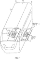
- FIG. 7 illustrates a vehicle 700 or passenger train 700a including the vehicle (e.g., passenger cabin 700b or train engine 700c) comprising magnetic modules 750 including magnets 702 configured to generate a magnetic field M2 that interacts with the track so as to levitate the vehicle above the track.
- the magnetic field M2 that allows for magnetic levitation is generated by an array of permanent magnets 702 on the vehicle that are oriented in a "Halbach array”.
- the magnetic modules 750 including the one or more magnets 702 are attached (connection 752) to the vehicle 700.
- FIG. 8 illustrates the Halbach array 800 is a certain configuration of permanent magnets that augments the magnetic flux density on one side of the array, and nearly negates it on the other.
- the Halbach array is oriented on the vehicle 700 such that the augmented magnetic field is interacting with the surface of the track 310.
- the magnets disposed in the Halbach array comprise an alloy of neodymium, iron, and boron.
- the Halbach array 800 can be optimized with longer wavelengths to increase the lift to drag ratio of the levitation system (wherein wavelength defined as the length between repeating sections of a Halbach array, as shown in FIG. 9 ).
- FIG. 10 illustrates lift to drag ratio as a function of wavelength of the Halbach array and speed, for different types of conductive track.
- the implementation of the Halbach array allows for a higher levitated mass per magnet mass, as it increases the efficiency (magnetic flux per unit mass) of the permanent magnets.
- the orientation and positioning of the magnets can be optimized for use with the conductive track and will still perform adequately during their interaction with the superconductor in the superconductive track (first portion).
- FIG.s 11A-11C illustrate the conductive region or portion (second portion 304) of the hybrid track 310 in a vacuum tunnel 1100 (i.e., the vehicle comprises a passenger train travelling on a track 310 in an evacuated tunnel to further reduce drag).
- FIG. 11A illustrates a rail (300) wherein the conductor (308) and the magnet (702) are disposed so as to form an electromagnetic suspension system (EMS) so that the vehicle (1104) levitates (L) when the second magnetic field (M2) interacts with the conductor (308) comprising a ferromagnetic material (1150).
- the magnets include electromagnets 1102 attached to the vehicle 1104, the electromagnets interfacing with the conductive track (second portion 304) comprising a (e.g., laminated ferromagnetic) track 1106.
- the electromagnets are actively controlled to provide a gap between the track 1106 and the magnets ranging from 1-4 cm.
- the electromagnets can be powered with a superconducting coil (reducing the energy requirement) and additional coils can be positioned to improve stability. Since the electromagnetic suspension system utilizes an attractive magnetic force between the conductive track 1106 and the electromagnets 1102, the track 1106 must be above the electromagnets. The attractive magnetic force between the electromagnets and the ferromagnetic track decays exponentially with increasing distance from the steel track.
- FIG. 11A illustrates the conductive track including a laminated ferromagnetic track, other ferromagnetic tracks can be used.
- the lift to drag ratio can range from 20 (for a solid ferromagnetic track) to (theoretically 100 or more using a laminated track).
- FIG. 11B illustrates a rail (300) wherein the conductor (308) and the magnet (702) are disposed so as to form an electrodynamic suspension system (EDS) so that the vehicle (1110) levitates in response to a second lift force F2 generated according to Lenz's law and a Lorentz force.
- EDS electrodynamic suspension system
- the magnets 1108 on the vehicle 1110 interface with the conductive track 1112 (second portion 304).
- permanent magnets are mounted on the vehicle in a single sided Halbach array with the conductive track 1112 including a ladder or Inductrack track surface as illustrated in FIG. 5 or FIG. 6 for example.
- the rail comprises 6061 aluminum (exampled dimensions include, but are not limited to, a track having a width of 12 feet and a thickness of 0.25 feet).
- the electrodynamic suspension system operates using Lenz's Law and the Lorentz Force, wherein a change in magnetic field in the conductive surface of the conductive track 1112 (caused by motion of magnets in the vehicle over the conductive track) generates eddy currents.
- the change in magnetic field in turn creates a magnetic field that opposes the change in magnetic field induced upon it. This causes opposing forces resulting in levitation of the vehicle.
- the EDS system exhibits a lift to drag ratio of 20, the gap between the vehicle and the conductive track is approximately 10 mm and the ratio of the mass of the vehicle to the magnet mass is 50:1.
- FIG. 12 is a flowchart illustrating a method of making and/or operating a rail system.
- Block 1200 represents obtaining or providing (e.g., assembling or laying) a track comprising a rail, the rail including first portion connected to a second portion, the first portion including a superconductor and the second portion including a conductor.
- the first portion (302) has a first tapered end (316) and the second portion (304) has a second tapered end (318), and the first tapered end (316) mates with the second tapered end (318).
- the first portion 302 connects to an outside 314 of the second portion 304 so as to increase lift stability on the outside of the track.
- superconductor examples include, but are not limited to, YBaCuO superconductive material or other high-temperature superconductive materials.
- the conductor 308 comprises a solid conductive plate 502 including slots 504 and rungs 506.
- the second portion 304 comprises a laminate 650, the laminate 650 including the conductor 308 disposed as conductive material 602 separated by an insulator 604.
- Example lengths L2 for the first portion include, but are not limited to, a length L2 in a range of 100 feet- 2000 feet or a length L2 sufficiently long for the vehicle 700 to reach a speed, when entering the second portion 304 from the first portion 302, such that the vehicle 700 experiences a lift to drag ratio exceeding the maximal lift to drag ratio of the second portion (e.g., more than 100).
- the length L2 is such that the vehicle 700 accelerates with a maximum acceleration of 1 g from an initial speed or velocity of 0 mph at one end 360 of the first portion 302 to a speed/velocity of at least 100 miles per hour at the other end 362 of the first portion 302 connected to the second portion 304.
- the first portion 302 comprises less than 0.1% of an entire length L3 of track 310 in the rail system 300b.
- Block 1202 represents optionally magnetically coupling a vehicle 700 to the track 310, wherein the vehicle comprises 700 a magnet 702 attached to the vehicle 700.
- the magnet 702 comprises a rare earth permanent magnet (e.g., a magnet comprising an alloy of neodymium, iron, and boron).
- the magnet 702 generates a magnetic field M2 interacting with the rail 300 (first portion 302 or second portion 304).
- Block 1204 represents optionally allowing the vehicle 700 to levitate L relative to the first portion 302 in response to a first lift force F1 generated when a first magnetic field M1 (generated using the superconductor 306 in a superconductive state) interacts with a second magnetic field M2 generated from the magnet 702 attached to the vehicle 700.
- a propulsion system connected to the vehicle 700 controls a speed/velocity of the vehicle 700 guided along the track 310 by the rails 300.
- Block 1206 represents optionally allowing the vehicle 700 to levitate L relative to the second portion 304 in response to a second lift force F2 generated when the second magnetic M2 field interacts with the conductor 308.
- a computer system 1300 connected to the vehicle 700 controls a speed of the vehicle 700 so that the vehicle 700 has a speed or velocity (entering the second portion 304 from the first portion 302) such that lift to drag ratio associated with the vehicle 700 is at its maximum value for the second portion 304.
- FIG. 13 illustrates an exemplary system 1300 used to implement processing elements needed to control the speed of the vehicle 1314, 700 so that the lift to drag ratio entering the conductive portion of the track is sufficiently high (e.g., greater than 100).
- the computer 1302 comprises a processor 1304 (general purpose processor 1304A and special purpose processor 1304B) and a memory, such as random access memory (RAM) 1306.
- the computer 1302 operates under control of an operating system 1308 stored in the memory 1306, and interfaces with the user/other computers to accept inputs and commands (e.g., analog or digital signals from the crew or automatic ice detector) and to present results through an input/output (I/O) module 1310.
- the computer program application 1312 accesses and manipulates data stored in the memory 1306 of the computer 1302.
- the operating system 1308 and the computer program 1312 are comprised of instructions which, when read and executed by the computer 1302, cause the computer 1302 to perform the operations and/or methods herein described.
- instructions implementing the operating system 1308 and the computer program 1312 are tangibly embodied in the memory 1306, thereby making one or more computer program products or articles of manufacture capable of controlling the speed of the vehicle on the hybrid track as described herein.
- the terms "article of manufacture,” “program storage device” and “computer program product” as used herein are intended to encompass a computer program accessible from any computer readable device or media.
Landscapes
- Engineering & Computer Science (AREA)
- Mechanical Engineering (AREA)
- Transportation (AREA)
- Power Engineering (AREA)
- Electromagnetism (AREA)
- Physics & Mathematics (AREA)
- Chemical & Material Sciences (AREA)
- Combustion & Propulsion (AREA)
- Structural Engineering (AREA)
- Civil Engineering (AREA)
- Architecture (AREA)
- Ceramic Engineering (AREA)
- Control Of Vehicles With Linear Motors And Vehicles That Are Magnetically Levitated (AREA)
Abstract
Description
- The present disclosure relates to a levitation system.
- Conventional passive electrodynamic suspension (EDS) levitation systems suffer from multiple drawbacks.
FIG. 1 illustrates a conventional system utilizing permanent magnets for levitation of a vehicle on a conductive track and requiring motion of the vehicle relative to the conductive track to achieve a levitation force. This motion drives a requirement for the inclusion of wheels, or another means to prevent the levitation module from contacting the surface of the track when travelling at speeds lower than the velocity at which levitation occurs. - Moreover, due to the creation and dissipation of eddy currents within the conductive plate in the conductive track (originating from the changing magnetic field over the surface of the conductive plate) a magnetic drag force resists the forward motion of the vehicle.
FIG. 2 illustrates the drag force increases and peaks at velocities around 10 mph, and then sharply decreases as the relative velocity increases. A large amount of power is required to overcome this drag force at relatively lower speeds (as compared to "cruise speeds" that are expected for use in high speed transport). - Systems that utilize tracks including a high temperature superconductive material are efficient, but extremely costly. While there is no magnetic drag associated with permanent magnets levitating over a superconductive track, there are small losses due to imperfections in the permanent magnetic field. The cost of the superconductive material for the entire length of the track, along with the cooling power associated with maintaining the entire track under a critical temperature required to achieve superconductivity, leads to high initial and operating costs that render conventional superconducting track technology unfeasible for longer routes.
- What is needed then, is a magnetic levitation rail system that is more energy and cost efficient as compared to a magnetic levitation rail system using conductive plates or superconductors. The present disclosure satisfies this need.
- The present disclosure describes a hybrid rail for a railway track. The rail comprises a first portion connected to a second portion, wherein the first portion includes a superconductor and the second portion includes a conductor. A vehicle magnetically coupled to a track including the rail levitates relative to the first portion when a first magnetic field interacts with a second magnetic field. The first magnetic field is generated using the superconductor in a superconductive state and the second magnetic field generated from a magnet attached to the vehicle. The vehicle levitates relative to the second portion when the second magnetic field interacts with the conductor.
- In a first aspect the present disclosure provides a rail as defined in claim 1. In a second aspect the present disclosure provides a rail system as defined in claim 12. In a third aspect the present disclosure provides a method as defined in claim 14.
- The rail can include the following examples.
- The first portion may have a first tapered end and the second portion may have a second tapered end, so that the first tapered end mates effectively with the second tapered end.
- The rail may include the first portion comprising an evacuated double walled tube having a first wall and second wall. The first wall may form/enclose a first volume, and the first wall and the second wall may form/enclose a second volume between the first and second wall. The superconductor may be disposed in the first volume
and the second volume comprises a vacuum. - The first portion may include the superconductor comprising a plurality of YBaCuO crystals.
- The conductor and the magnet may be disposed so as to form an electromagnetic suspension system (EMS) so that the vehicle levitates L in response to a second lift force generated when the second magnetic field interacts with the conductor comprising a ferromagnetic material.
- The conductor and the magnet may be disposed so as to form an electrodynamic suspension system EDS so that the
vehicle 1110 levitates in response to a second lift force F2 generated according to Lenz's law and a Lorentz force. - The conductor may comprise a solid conductive plate including slots and rungs.
- The second portion may comprise a laminate, the laminate including the conductor disposed as conductive material separated by an insulator.
- The magnet may be disposed in a Halbach array.
- The first portion may have a length in a range of 100 feet- 2000 feet.
- The first portion may have a length sufficiently long for the vehicle to reach a speed, when entering the second portion from the first portion, such that the vehicle experiences a lift to drag ratio exceeding the maximal lift to drag ratio of the second portion.
- In yet another example, the length in example 11 may be such that the vehicle accelerates with a maximum acceleration of 1 g from an initial speed of 0 mph at one end of the first portion to a speed of at least 100 miles per hour at the other end of the first portion connected to the second portion.
- A rail system may include the rail of one or any combination of the previous examples, wherein the first portion comprises less than 0.1% of an entire length of track in the rail system.
- The rail system may further comprise a computer configured to control a speed of the vehicle on the rail system, wherein the speed when entering the second portion from the first portion may be such that the vehicle experiences a lift to drag ratio of at least 100 or exceeding the maximal lift to drag ratio of the
second portion 304. - The first portion of the rail may include a first section and a second section, and the second portion between the first section and the second section.
- The vehicle may comprise a passenger train.
The present disclosure further describes a method of operating a vehicle, comprising operating the vehicle on a track including a rail, the rail including a first portion connected to a second portion, and the first portion including a superconductor and the second portion including a conductor. The vehicle magnetically coupled to the track: - (1) levitates relative to the first portion in response to a first lift force generated when a first magnetic field generated using the superconductor in a superconductive state interacts with a second magnetic field generated from a magnet attached to the vehicle, and
- (2) levitates relative to the second portion in response to a second lift force generated when the second magnetic field interacts with the conductor.
- (1) levitates relative to the first portion in response to a first lift force generated when a first magnetic field generated using the superconductor in a superconductive state interacts with a second magnetic field generated from a magnet attached to the vehicle,
- (2) levitates relative to the second portion in response to a second lift force generated when the second magnetic field interacts with the conductor, and
- (3) has a speed entering the second portion from the first portion such that lift to drag ratio associated with the vehicle is at its maximum value for the second portion of the track.
-
-
FIG. 1 illustrates a typical EDS levitation system. -
FIG. 2 illustrates typical lift and drag forces found in passive EDS systems. -
FIG. 3A illustrates a hybrid electrodynamic levitation system including a transition region between the superconductive track and the conductive track, according to one or more examples. -
FIG. 3B illustrates a hybrid electrodynamic levitation system according to one or more examples, illustrating an exemplary length of superconductive track in comparison to the length of conductive track (conductive track much longer than superconductive track, not shown to scale). In this example, the conductive track has length of 300 miles (mi) and the portions of superconductive track each have a length of 300 feet. -
FIG. 4 illustrates an exemplary housing for superconductive material in the superconductive region of the hybrid system. -
FIG. 5 illustrates an exemplary conductive track in the hybrid system, wherein the conductive track includes a conductive slotted track and optimization of the track parameters depends upon magnet geometry, vehicle speed, and desired lifting force. -
FIG. 6 illustrates another exemplary conductive track in the hybrid system, wherein the conductive track comprises a laminate. -
FIG. 7 illustrates Halbach arrays arranged on the base of a vehicle on levitation modules, wherein the Halbach arrays interact with the hybrid track or hybrid track surfaces so as to levitate the vehicle. -
FIG. 8 illustrates an example orientation of the permanent magnets in a Halbach array used on a vehicle traveling on the hybrid levitation system. -
FIG. 9 is an exemplary visual depiction of the wavelength of a Halbach array. -
FIG. 10 illustrates lift to drag ratio as a function of vehicle speed, for different types of conductive track coupled to a vehicle including a Halbach array, reproduced from "the inductrack approach to magnetic levitation' by Post et. al., https://e-reports-ext.llnl.gov/pdf/237852.pdf. -
FIG. 11A illustrates an exemplary electromagnetic suspension system that can be used in the conductive section of the hybrid levitation system. -
FIG. 11B illustrates an exemplary electrodynamic suspension system that can be used in the conductive section of the hybrid levitation system. -
FIG. 12 is a flowchart illustrating a method for making and operating a rail system according to one or more examples. -
FIG. 13 illustrates an exemplary hardware environment for controlling speed of a vehicle coupled to the hybrid track. - In the following description, reference is made to the accompanying drawings which form a part hereof, and which is shown, by way of illustration, several examples. It is understood that other examples may be utilized and structural changes may be made without departing from the scope of the present disclosure.
-
FIG. 3A illustrates arail 300 including afirst portion 302 connected to asecond portion 304, thefirst portion 302 including asuperconductor 306 and thesecond portion 304 including aconductor 308. A vehicle magnetically coupled to atrack 310 including therail 300 levitates relative to the first portion in response to a first lift force F1 generated when a first magnetic field M1 (generated using the superconductor in a superconductive state) interacts with a second magnetic field M2 (generated from a magnet attached to the vehicle). The vehicle levitates relative to the second portion in response to a second lift force F2 generated when the second magnetic field M2 interacts with the conductor in the second portion. - Also shown is a
transition zone 312 between first portion and the second portion. In thetransition zone 312, thefirst portion 302 connects to an outside 314 of thesecond portion 304 so as to increase lift stability on the outside of the track. The amount of the first portion in the transition zone is reduced moving towards the second portion. In the example transition zone illustrated inFIG. 3A , the first portion has a firsttapered end 316, the second portion has a secondtapered end 318, and the first tapered end mates with/is physically attached to the secondtapered end 318. More specifically, as viewed from the top, the first tapered end comprises a firsttriangular cross-section 320 having afirst hypotenuse 322 in a plane comprising afirst surface 324, the second tapered end comprises a secondtriangular cross-section 326 having asecond hypotenuse 328 in a plane comprising asecond surface 330, and thefirst surface 324 mates or is attached to thesecond surface 330. In one or more examples, the transition zone has a length of 50-200 feet (e.g., 75 feet).
FIG. 3B illustrates a rail system 300b comprising a track including the conductive portion (second portion 304) in between or in the middle of two superconductive portions (first section 332 and second section 334). In other words, thefirst portion 302 comprises thefirst section 332 andsecond section 334 and thesecond portion 304 is between (or in the middle of) thefirst section 332 andsecond section 334. - The lengths of the superconductive tracks (first and second sections of the track) are determined by how long it takes the vehicle traveling on the superconductive track to reach speeds higher than the peak drag value. However, in typical examples, the first portion comprising the superconductive track is shorter than the second portion comprising the conductive track. The superconductive track (first and second sections) are acceleration zones at the beginning and end of the track that (1) allow for levitation of the vehicle with no relative velocity of the vehicle relative to the track, thereby eliminating the need for wheels or additional means of rolling, and (2) increase efficiency of acceleration by eliminating magnetic drag force. In one example, assuming a maximum acceleration value of 1g to ensure passenger comfort, a speed exceeding 100 mph is achieved after travelling approximately 300 or 400 feet on the first portion including superconductive track. This high speed exceeding 100 mph ensures an adequately high lift to drag ratio when entering into the conductive track (middle or second portion) from the first portion comprising superconductive track.
- In one example that seeks to minimize costs, the lengths of the first and second sections including the superconductive track are a minute percentage (<0.1%) of the entire length of the track so as to minimize cost and energy consumption (e.g., due to cooling requirements for the superconductive track). In one or more examples, the conductive track (second portion) has a length of at least 300 miles.
- In one or more examples, the first portion comprising the superconductive region of track requires cooling e.g., using liquid nitrogen or a refrigeration cycle. For example, liquid nitrogen with a boiling point of 77 K can be used to cool the superconductor (e.g., high temperature superconductive material, e.g., YBaCuO superconductors that maintain superconductivity at temperatures lower than 92 K). Refueling of the liquid nitrogen or additional power can be used to keep the superconductive track beneath the critical temperature required to maintain the superconductive state of the superconductor.
-
FIG. 4 illustrates thefirst portion 302 of track includes a cryostat/cryostat chamber 400 comprising an evacuated doublewalled tube 402 having a first wall 404 andsecond wall 406. The first wall forms or encloses afirst volume 408, and asecond volume 410 is formed or enclosed between the first wall and the second wall. In one or more examples, the cryostat andwalls 404, 406 are fabricated from stainless steel. - The superconductor comprising
superconductive material 412 is disposed or contained in the first volume.FIG. 4 further illustrates the cryostat housing superconductive material includingsuperconductive crystals 414 disposed in a grid like fashion. The sizing of the superconductive crystals is based on the optimal grain size of the superconductive material. In one example, the crystals are YBaCuO crystals that are approximately 2.5" x 1.25" x 0.5". - The second volume between the first and second walls is evacuated so as to form
vacuum 450 insulation which eliminates nearly all heat transfer. The additional low pressure environment in the second volume in the tube also results in decreased heat convection from the outside environment, thereby aiding in keeping the track at low temperatures. The cryostat can be actively cooled using refrigeration technology (the expected power consumption for actively cooling is on the order of 1-5 kilowatts for a total of 1200 ft of cooled track, corresponding to between 0.5- 5 Watts per foot) or refilled with liquid nitrogen as needed. In one example, the first volume also contains the coolant (e.g., liquid nitrogen or other refrigerant) used to cool the superconductive material into a superconducting state. A valve can be connected to the first volume and configured to receive and transfer the coolant into the first or second volume. - The superconductive track width can be scaled with the size of the levitated mass. A track designed to be approximately 12 inches in width can levitate a 40,000 pound (lb) vehicle (although track width doesn't impact the weight of vehicle that can be levitated, since the longer the vehicle, the heavier the vehicle that can be levitated.
- The main portion (second portion 304) of the track is comprised of a low cost conductive track that is optimized for a high lift to drag ratio. The track may be slotted or laminated to increase the inductance and therefore the lift to drag ratio, for example.
FIG. 5 illustrates a slottedtrack 500 comprised of a solidconductive plate 502 with a machined out geometry. The geometry of theslots 504 andrungs 506 that comprise the track can be optimized in relation to the magnet geometry, vehicle speed, and desired lifting force. Example dimensions include, but are not limited to, a slot width WSLOT and a slot length LSLOT in a range of 1-2 feet, a rung length (Lrung) in a range of 0.2-0.75 feet, and a track width Wtrack in a range of 0.5-3 feet. Example materials for the conductive plate include, but are not limited to, aluminum. Example lift to drag ratios of at least 50 have been measured using this track configuration.
FIG. 6 illustrates alaminated track 600 example comprised of conductive material 602 (e.g., aluminum) separated every few mm (e.g., spacing in a range of 1-10 mm) by a nonconductive material orinsulator 604 such as, but not limited to, thin plastic sheets or anodized aluminum. Example dimensions for the laminated track include, but are not limited to, a track width Wtrack in a range of 0.5- 2 feet (e.g., 1 foot). Theoretical lift to drag ratios for these dimensions exceed 150 at speeds greater than 100 mph. The spacing S between the conductive material can be set so as to localize the eddy currents. - Implementation of the conductive track is extremely cost efficient in comparison to the use of superconductive track. The use of a conductive track in the high speed portions of the track leads to a smaller amount of losses due to magnetic drag, but also provides a fail-safe mode of levitation. If power to the track or vehicle is lost, the vehicle will continue stable levitation until it reaches speeds of around 10 mph.
-
FIG. 7 illustrates avehicle 700 orpassenger train 700a including the vehicle (e.g.,passenger cabin 700b ortrain engine 700c) comprisingmagnetic modules 750 includingmagnets 702 configured to generate a magnetic field M2 that interacts with the track so as to levitate the vehicle above the track. In the example ofFIG. 7 , the magnetic field M2 that allows for magnetic levitation is generated by an array ofpermanent magnets 702 on the vehicle that are oriented in a "Halbach array". Themagnetic modules 750 including the one ormore magnets 702 are attached (connection 752) to thevehicle 700.FIG. 8 illustrates theHalbach array 800 is a certain configuration of permanent magnets that augments the magnetic flux density on one side of the array, and nearly negates it on the other. The Halbach array is oriented on thevehicle 700 such that the augmented magnetic field is interacting with the surface of thetrack 310. In one or more examples, the magnets disposed in the Halbach array comprise an alloy of neodymium, iron, and boron. - The
Halbach array 800 can be optimized with longer wavelengths to increase the lift to drag ratio of the levitation system (wherein wavelength defined as the length between repeating sections of a Halbach array, as shown inFIG. 9 ).FIG. 10 illustrates lift to drag ratio as a function of wavelength of the Halbach array and speed, for different types of conductive track.
The implementation of the Halbach array allows for a higher levitated mass per magnet mass, as it increases the efficiency (magnetic flux per unit mass) of the permanent magnets. The orientation and positioning of the magnets can be optimized for use with the conductive track and will still perform adequately during their interaction with the superconductor in the superconductive track (first portion). -
FIG.s 11A-11C illustrate the conductive region or portion (second portion 304) of thehybrid track 310 in a vacuum tunnel 1100 (i.e., the vehicle comprises a passenger train travelling on atrack 310 in an evacuated tunnel to further reduce drag). -
FIG. 11A illustrates a rail (300) wherein the conductor (308) and the magnet (702) are disposed so as to form an electromagnetic suspension system (EMS) so that the vehicle (1104) levitates (L) when the second magnetic field (M2) interacts with the conductor (308) comprising a ferromagnetic material (1150). In one or more examples, the magnets includeelectromagnets 1102 attached to thevehicle 1104, the electromagnets interfacing with the conductive track (second portion 304) comprising a (e.g., laminated ferromagnetic)track 1106. In one or more examples, the electromagnets are actively controlled to provide a gap between thetrack 1106 and the magnets ranging from 1-4 cm. Feedback from proximity sensors feeds into electromagnets to maintain a constant gap. The electromagnets can be powered with a superconducting coil (reducing the energy requirement) and additional coils can be positioned to improve stability. Since the electromagnetic suspension system utilizes an attractive magnetic force between theconductive track 1106 and theelectromagnets 1102, thetrack 1106 must be above the electromagnets. The attractive magnetic force between the electromagnets and the ferromagnetic track decays exponentially with increasing distance from the steel track. Although the example ofFIG. 11A illustrates the conductive track including a laminated ferromagnetic track, other ferromagnetic tracks can be used. The lift to drag ratio can range from 20 (for a solid ferromagnetic track) to (theoretically 100 or more using a laminated track). -
FIG. 11B illustrates a rail (300) wherein the conductor (308) and the magnet (702) are disposed so as to form an electrodynamic suspension system (EDS) so that the vehicle (1110) levitates in response to a second lift force F2 generated according to Lenz's law and a Lorentz force. In one or more examples, themagnets 1108 on thevehicle 1110 interface with the conductive track 1112 (second portion 304). In an example passive system, permanent magnets are mounted on the vehicle in a single sided Halbach array with theconductive track 1112 including a ladder or Inductrack track surface as illustrated inFIG. 5 orFIG. 6 for example. In another example passive system, permanent magnets are mounted on the vehicle in a double Halbach array (Null Flux) with the conductive track including a ladder or Inductrack track surface. In yet another example passive system, permanent magnets are mounted on the vehicle in a single sided Halbach array with the conductive track comprising loops (Null Flux). In one example, the rail comprises 6061 aluminum (exampled dimensions include, but are not limited to, a track having a width of 12 feet and a thickness of 0.25 feet). - Without being bound by a particular scientific theory, the electrodynamic suspension system operates using Lenz's Law and the Lorentz Force, wherein a change in magnetic field in the conductive surface of the conductive track 1112 (caused by motion of magnets in the vehicle over the conductive track) generates eddy currents. The change in magnetic field in turn creates a magnetic field that opposes the change in magnetic field induced upon it. This causes opposing forces resulting in levitation of the vehicle.
- In one or more examples, the EDS system exhibits a lift to drag ratio of 20, the gap between the vehicle and the conductive track is approximately 10 mm and the ratio of the mass of the vehicle to the magnet mass is 50:1.
-
FIG. 12 is a flowchart illustrating a method of making and/or operating a rail system.Block 1200 represents obtaining or providing (e.g., assembling or laying) a track comprising a rail, the rail including first portion connected to a second portion, the first portion including a superconductor and the second portion including a conductor. In one or more examples, the first portion (302) has a first tapered end (316) and the second portion (304) has a second tapered end (318), and the first tapered end (316) mates with the second tapered end (318). In this way, thefirst portion 302 connects to an outside 314 of thesecond portion 304 so as to increase lift stability on the outside of the track. - Examples of superconductor include, but are not limited to, YBaCuO superconductive material or other high-temperature superconductive materials.
- In one or more examples, the
conductor 308 comprises a solidconductive plate 502 includingslots 504 andrungs 506. - In one or more examples, the
second portion 304 comprises a laminate 650, the laminate 650 including theconductor 308 disposed asconductive material 602 separated by aninsulator 604. Example lengths L2 for the first portion include, but are not limited to, a length L2 in a range of 100 feet- 2000 feet or a length L2 sufficiently long for thevehicle 700 to reach a speed, when entering thesecond portion 304 from thefirst portion 302, such that thevehicle 700 experiences a lift to drag ratio exceeding the maximal lift to drag ratio of the second portion (e.g., more than 100). In one or more examples, the length L2 is such that thevehicle 700 accelerates with a maximum acceleration of 1 g from an initial speed or velocity of 0 mph at oneend 360 of thefirst portion 302 to a speed/velocity of at least 100 miles per hour at theother end 362 of thefirst portion 302 connected to thesecond portion 304. In one or more further examples, thefirst portion 302 comprises less than 0.1% of an entire length L3 oftrack 310 in the rail system 300b. -
Block 1202 represents optionally magnetically coupling avehicle 700 to thetrack 310, wherein the vehicle comprises 700 amagnet 702 attached to thevehicle 700. In one or more examples, themagnet 702 comprises a rare earth permanent magnet (e.g., a magnet comprising an alloy of neodymium, iron, and boron). Themagnet 702 generates a magnetic field M2 interacting with the rail 300 (first portion 302 or second portion 304). -
Block 1204 represents optionally allowing thevehicle 700 to levitate L relative to thefirst portion 302 in response to a first lift force F1 generated when a first magnetic field M1 (generated using thesuperconductor 306 in a superconductive state) interacts with a second magnetic field M2 generated from themagnet 702 attached to thevehicle 700. - A propulsion system connected to the
vehicle 700 controls a speed/velocity of thevehicle 700 guided along thetrack 310 by therails 300. -
Block 1206 represents optionally allowing thevehicle 700 to levitate L relative to thesecond portion 304 in response to a second lift force F2 generated when the second magnetic M2 field interacts with theconductor 308. - A
computer system 1300 connected to thevehicle 700 controls a speed of thevehicle 700 so that thevehicle 700 has a speed or velocity (entering thesecond portion 304 from the first portion 302) such that lift to drag ratio associated with thevehicle 700 is at its maximum value for thesecond portion 304. -
FIG. 13 illustrates anexemplary system 1300 used to implement processing elements needed to control the speed of thevehicle - The
computer 1302 comprises a processor 1304 (general purpose processor 1304A andspecial purpose processor 1304B) and a memory, such as random access memory (RAM) 1306. Generally, thecomputer 1302 operates under control of anoperating system 1308 stored in thememory 1306, and interfaces with the user/other computers to accept inputs and commands (e.g., analog or digital signals from the crew or automatic ice detector) and to present results through an input/output (I/O)module 1310. Thecomputer program application 1312 accesses and manipulates data stored in thememory 1306 of thecomputer 1302. Theoperating system 1308 and thecomputer program 1312 are comprised of instructions which, when read and executed by thecomputer 1302, cause thecomputer 1302 to perform the operations and/or methods herein described. In one example, instructions implementing theoperating system 1308 and thecomputer program 1312 are tangibly embodied in thememory 1306, thereby making one or more computer program products or articles of manufacture capable of controlling the speed of the vehicle on the hybrid track as described herein. As such, the terms "article of manufacture," "program storage device" and "computer program product" as used herein are intended to encompass a computer program accessible from any computer readable device or media. - Further, the disclosure comprises examples according to the following clauses:
- Clause 1. A rail, comprising:
a first portion connected to a second portion, the first portion including a superconductor and the second portion including a conductor, wherein a vehicle magnetically coupled to a track including the rail:- levitates relative to the first portion when a first magnetic field interacts with a second magnetic field, the first magnetic field generated using the superconductor in a superconductive state and the second magnetic field generated from a magnet attached to the vehicle, and
- levitates relative to the second portion when the second magnetic field interacts with the conductor.
- Clause 2. The rail of Clause 1, wherein:
- the first portion has a first tapered end and the second portion has a second tapered end, and
- the first tapered end mates with the second tapered end.
- Clause 3. The rail of Clause 2, wherein:
- the first portion comprises an evacuated double walled tube having a first wall and second wall, the first wall forming a first volume, the first wall and the second wall forming a second volume between the first wall and second wall;
- the superconductor is disposed in the first volume, and
- the second volume comprises a vacuum.
-
Clause 4. The rail of Clause 3, wherein the superconductor comprises a plurality of YBaCuO crystals. - Clause 5. The rail of any preceding Clause, wherein the conductor and the magnet are disposed so as to form an electromagnetic suspension system so that the vehicle levitates in response to a second lift force F2 generated when the second magnetic field interacts with the conductor comprising a ferromagnetic material.
-
Clause 6. The rail of any preceding Clause, wherein the conductor and the magnet are disposed so as to form an electrodynamic suspension system so that the vehicle levitates in response to a second lift force F2 generated according to Lenz's law and a Lorentz force. - Clause 7. The rail of any preceding Clause, wherein the conductor comprises a solid conductive plate including slots and rungs.
- Clause 8. The rail of any preceding Clause, wherein the second portion comprises a laminate, the laminate including the conductor disposed as conductive material separated by an insulator.
- Clause 9. The rail of any preceding Clause, wherein the magnet is disposed in a Halbach array.
-
Clause 10. The rail of any preceding Clause, wherein the first portion has a length in a range of 100 feet- 2000 feet. - Clause 11. The rail of any preceding Clause, wherein the first portion has a length sufficiently long for the vehicle to reach a speed, when entering the second portion from the first portion, such that the vehicle experiences a lift to drag ratio exceeding the maximal lift to drag ratio of the second portion.
- Clause 12. The rail of any preceding Clause, wherein the length is such that the vehicle accelerates with a maximum acceleration of 1 g from an initial speed of 0 mph at one end of the first portion to a speed of at least 100 miles per hour at the other end of the first portion connected to the second portion.
- Clause 13. A rail system including the rail of any preceding Clause, wherein the first portion comprises less than 0.1% of an entire length of track in the rail system.
- Clause 14. The rail system of Clause 13, further comprising a computer configured to control a speed of the vehicle on the rail system, wherein the speed when entering the second portion from the first portion is such that the vehicle experiences a lift to drag ratio of at least 100 or exceeding the maximal lift to drag ratio of the second portion.
- Clause 15. The rail of any preceding Clause, wherein the first portion includes a first section and a second section and the second portion between the first section and the second section.
- Clause 16. The rail of any preceding Clause, wherein the vehicle is in a passenger train.
- Clause 17. A method of operating a vehicle, comprising:
- operating the vehicle on a track including a rail, the rail including a first portion connected to a second portion, the first portion including a superconductor and the second portion including a conductor,
- wherein the vehicle magnetically coupled to the track:
- levitates relative to the first portion in response to a first lift force generated when a first magnetic field generated using the superconductor in a superconductive state interacts with a second magnetic field generated from a magnet attached to the vehicle, and
- levitates relative to the second portion in response to a second lift force generated when the second magnetic field interacts with the conductor.
- Clause 18. The method of Clause 17, wherein the first portion has a length sufficiently long for the vehicle to reach a speed, when entering the second portion from the first portion, such that the vehicle experiences a lift to drag ratio exceeding the maximal lift to drag ratio of the second portion.
- Clause 19. A vehicle, comprising:
- a magnet attached to the vehicle, the magnet generating a magnetic field interacting with a rail including a first portion connected to a second portion, the first portion including a superconductor and the second portion including a conductor; and
- a computer system connected to the vehicle controlling a speed of the vehicle, wherein the vehicle:
- levitates relative to the first portion in response to a first lift force generated when a first magnetic field generated using the superconductor in a superconductive state interacts with a second magnetic field generated from a magnet attached to the vehicle,
- levitates relative to the second portion in response to a second lift force generated when the second magnetic field interacts with the conductor, and
- has a speed entering the second portion from the first portion such that lift to drag ratio associated with the vehicle is at its maximum value for the second portion.
-
Clause 20. A passenger train comprising the vehicle of Clause 19. - Those skilled in the art will recognize many modifications may be made to this configuration without departing from the scope of the present disclosure. For example, those skilled in the art will recognize that any combination of the above components, or any number of different components, peripherals, and other devices, may be used.
- The implementation of a hybrid superconductive/conductive track according one or more examples described herein solves the following problems:
- The requirement for wheels or additional means to prevent contact of levitation modules with the track and which slows the vehicle down. Vehicles described herein that do not require wheels assist with the acceleration of the vehicle.
- Decreased efficiency due to low lift to drag ratio. Embodiments of the rail system described herein aids acceleration of vehicles (e.g., in evacuated tubes) by ensuring that the vehicle enters the conductive region with an adequately high lift to drag ratio. Embodiments of the rail system described herein increase the efficiency of acceleration to cruise speeds by at least 50%.
- High costs. Embodiments of the rail system described herein reduce both overall initial and operating costs.
- Levitation failure. Embodiments of the hybrid rail system described herein enable fail-safe levitation in high-speed regions.
- This concludes the description of the preferred embodiments of the present disclosure. The foregoing description of the preferred embodiment has been presented for the purposes of illustration and description. It is not intended to be exhaustive or to limit the disclosure to the precise form disclosed. Many modifications and variations are possible in light of the above teaching. It is intended that the scope of rights be limited not by this detailed description, but rather by the claims appended hereto.
Claims (15)
- A rail (300), comprising:
a first portion (302) connected to a second portion (304), the first portion (302) including a superconductor (306) and the second portion (304) including a conductor (308), wherein a vehicle (700) magnetically coupled to a track (310) including the rail (300):levitates (L) relative to the first portion (302) when a first magnetic field (M1) interacts with a second magnetic field (M2), the first magnetic field (M1) generated using the superconductor (306) in a superconductive state and the second magnetic field (M2) generated from a magnet (702) attached to the vehicle (700), andlevitates (L) relative to the second portion (304) when the second magnetic field (M2) interacts with the conductor (308). - The rail (300) of claim 1, wherein:the first portion (302) has a first tapered end (316) and the second portion (304) has a second tapered end (318), andthe first tapered end (316) mates with the second tapered end (318).
- The rail (300) of claim 2, wherein:the first portion (302) comprises an evacuated double walled tube (402) having a first wall (404) and second wall (406), the first wall (404) forming a first volume (408), the first wall (404) and the second wall (406) forming a second volume (410) between the first wall (404) and second wall (406);the superconductor (306) is disposed in the first volume (408), andthe second volume (410) comprises a vacuum (450).
- The rail (300) of any preceding claim, wherein the superconductor (306) comprises a plurality of YBaCuO crystals (414).
- The rail (300) of any one of claims 1-4, wherein the conductor (308) and the magnet (702) are disposed so as to form an electromagnetic suspension system (EMS) so that the vehicle (1104) levitates (L) in response to a second lift force F2 generated when the second magnetic field (M2) interacts with the conductor (308) comprising a ferromagnetic material (1150).
- The rail (300) of any one of claims 1-5, wherein the conductor (308) comprises a solid conductive plate (502) including slots (504) and rungs (506).
- The rail (300) of any one of claims 1-6, wherein the second portion (304) comprises a laminate (650), the laminate (650) including the conductor (308) disposed as conductive material (602) separated by an insulator (604).
- The rail (300) of any one of claims 1-7, wherein the magnet (702) is disposed in a Halbach array (800).
- The rail (300) of any one of claims 1-8, wherein the first portion (302) has a length (L2) in a range of 100 feet- 2000 feet.
- The rail (300) of any one of claims 1-9, wherein the first portion (302) has a length (L2) sufficiently long for the vehicle (700) to reach a speed, when entering the second portion (304) from the first portion (302), such that the vehicle (700) experiences a lift to drag ratio exceeding the maximal lift to drag ratio of the second portion (304).
- The rail (300) of any one of claims 1-10, wherein the length (L2) is such that the vehicle (700) accelerates with a maximum acceleration of 1 g from an initial speed of 0 mph at one end (360) of the first portion (302) to a speed of at least 100 miles per hour at the other end (362) of the first portion (302) connected to the second portion (304).
- A rail system (300b) including the rail (300) of any one of claims 1-11, wherein the first portion (302) comprises less than 0.1% of an entire length (L3) of track (310) in the rail system (300b).
- The rail system (300b) of claim 12, further comprising a computer (1302) configured to control a speed of the vehicle (700) on the rail system (300b), wherein the speed when entering the second portion (304) from the first portion (302) is such that the vehicle (700) experiences a lift to drag ratio of at least 100 or exceeding the maximal lift to drag ratio of the second portion (304).
- A method of operating a vehicle (700), comprising:
operating the vehicle (700) on a track (310) including a rail (300), the rail (300) including a first portion (302) connected to a second portion (304), the first portion (302) including a superconductor (306) and the second portion (304) including a conductor (308), wherein the vehicle (700) magnetically coupled to the track (310):levitates (L) relative to the first portion (302) in response to a first lift force generated when a first magnetic field (M1) generated using the superconductor (306) in a superconductive state interacts with a second magnetic field (M2) generated from a magnet (702) attached to the vehicle (700), andlevitates (L) relative to the second portion (304) in response to a second lift force generated when the second magnetic field (M2) interacts with the conductor (308). - The method of claim 14, wherein the first portion (302) has a length (L2) sufficiently long for the vehicle (700) to reach a speed, when entering the second portion (304) from the first portion (302), such that the vehicle (700) experiences a lift to drag ratio exceeding the maximal lift to drag ratio of the second portion (304).
Applications Claiming Priority (1)
| Application Number | Priority Date | Filing Date | Title |
|---|---|---|---|
| US16/055,729 US11230195B2 (en) | 2018-08-06 | 2018-08-06 | Hybrid electrodynamic levitation system |
Publications (2)
| Publication Number | Publication Date |
|---|---|
| EP3611046A1 true EP3611046A1 (en) | 2020-02-19 |
| EP3611046B1 EP3611046B1 (en) | 2024-02-14 |
Family
ID=67439140
Family Applications (1)
| Application Number | Title | Priority Date | Filing Date |
|---|---|---|---|
| EP19188709.0A Active EP3611046B1 (en) | 2018-08-06 | 2019-07-26 | Hybrid electrodynamic levitation system |
Country Status (5)
| Country | Link |
|---|---|
| US (1) | US11230195B2 (en) |
| EP (1) | EP3611046B1 (en) |
| JP (1) | JP7398897B2 (en) |
| KR (1) | KR20200016165A (en) |
| CN (1) | CN110803029B (en) |
Cited By (1)
| Publication number | Priority date | Publication date | Assignee | Title |
|---|---|---|---|---|
| CN115366692A (en) * | 2022-10-26 | 2022-11-22 | 成都西交华创科技有限公司 | High-temperature superconducting magnetic levitation train preparation system and method and steel rail top height calculation method |
Families Citing this family (3)
| Publication number | Priority date | Publication date | Assignee | Title |
|---|---|---|---|---|
| US11230195B2 (en) * | 2018-08-06 | 2022-01-25 | The Boeing Company | Hybrid electrodynamic levitation system |
| CN113265914A (en) * | 2021-05-27 | 2021-08-17 | 江西理工大学 | Permanent magnetic suspension track and permanent magnetic suspension track system |
| CN113415171B (en) * | 2021-07-07 | 2022-10-21 | 西南交通大学 | Suspension driving integrated magnetic suspension system and suspension driving method |
Citations (2)
| Publication number | Priority date | Publication date | Assignee | Title |
|---|---|---|---|---|
| US6758146B2 (en) * | 2001-06-29 | 2004-07-06 | The Regents Of The University Of California | Laminated track design for inductrack maglev systems |
| CN208278048U (en) * | 2018-06-06 | 2018-12-25 | 北京九州动脉隧道技术有限公司 | A kind of conductivity magnetic levitation transport system |
Family Cites Families (15)
| Publication number | Priority date | Publication date | Assignee | Title |
|---|---|---|---|---|
| JPS49113315A (en) * | 1973-03-07 | 1974-10-29 | ||
| JPS63249404A (en) * | 1987-04-02 | 1988-10-17 | Mitsubishi Electric Corp | Magnetic levitation device |
| JPS63287305A (en) * | 1987-05-15 | 1988-11-24 | Sumitomo Electric Ind Ltd | Magnetic leuitaion vehicle |
| JPS6426307A (en) * | 1987-07-22 | 1989-01-27 | Hitachi Ltd | Induction repulsing type magnetic levitation train |
| US4858511A (en) * | 1988-03-14 | 1989-08-22 | The United States Of America As Represented By The Secretary Of The Army | Superconductive levitated armatures for electromagnetic launchers |
| JPH0333302A (en) * | 1989-06-29 | 1991-02-13 | Sumitomo Electric Ind Ltd | Track structure of magnetic levitation cart |
| US5282424A (en) * | 1991-11-18 | 1994-02-01 | Neill Gerard K O | High speed transport system |
| JP3251654B2 (en) * | 1992-08-25 | 2002-01-28 | 株式会社東芝 | System for levitating and guiding objects by magnetic force |
| EP1381531B1 (en) | 2001-04-24 | 2016-11-02 | Leibniz-Institut für Festkörper- und Werkstoffforschung Dresden e.V. | Magnet assembly for the suspension and guidance of suspended vehicles and transport systems |
| CN1288018C (en) * | 2001-09-18 | 2006-12-06 | 西南交通大学 | Superconductive magnetic suspension train system |
| US7073513B2 (en) * | 2003-05-27 | 2006-07-11 | The University Of Chicago | Superconducting magnetic control system for manipulation of particulate matter and magnetic probes in medical and industrial applications |
| CN102653247A (en) * | 2011-03-04 | 2012-09-05 | 吴小平 | Blade-adjusted-type permanent magnetic suspension technology |
| DE102015001746A1 (en) * | 2015-02-11 | 2016-08-11 | Karlsruher Institut für Technologie | Rail-bound maglev train |
| CN105691408B (en) * | 2016-03-24 | 2018-12-25 | 西南交通大学 | High-temperature superconducting magnetic levitation tracks of permanent magnetism magnetic field super-high structure |
| US11230195B2 (en) * | 2018-08-06 | 2022-01-25 | The Boeing Company | Hybrid electrodynamic levitation system |
-
2018
- 2018-08-06 US US16/055,729 patent/US11230195B2/en active Active
-
2019
- 2019-07-19 KR KR1020190087440A patent/KR20200016165A/en not_active Application Discontinuation
- 2019-07-26 EP EP19188709.0A patent/EP3611046B1/en active Active
- 2019-08-02 CN CN201910710566.6A patent/CN110803029B/en active Active
- 2019-08-05 JP JP2019143681A patent/JP7398897B2/en active Active
Patent Citations (2)
| Publication number | Priority date | Publication date | Assignee | Title |
|---|---|---|---|---|
| US6758146B2 (en) * | 2001-06-29 | 2004-07-06 | The Regents Of The University Of California | Laminated track design for inductrack maglev systems |
| CN208278048U (en) * | 2018-06-06 | 2018-12-25 | 北京九州动脉隧道技术有限公司 | A kind of conductivity magnetic levitation transport system |
Non-Patent Citations (2)
| Title |
|---|
| ÍÑIGUEZ J ET AL: "Laboratory scale prototype of a low-speed electrodynamic levitation system based on a Halbach magnet array", EUROPEAN JOURNAL OF PHYSICS, INSTITUTE OF PHYSICS PUBLISHING, BRISTOL, GB, vol. 30, no. 2, 1 March 2009 (2009-03-01), pages 367 - 379, XP020150043, ISSN: 0143-0807, DOI: 10.1088/0143-0807/30/2/016 * |
| JAYAWANT B V ET AL: "REVIEW ARTICLE; Electromagnetic suspension and levitation", REPORTS ON PROGRESS IN PHYSICS, INSTITUTE OF PHYSICS PUBLISHING, BRISTOL, GB, vol. 44, no. 4, 1 April 1981 (1981-04-01), pages 411 - 477, XP020024719, ISSN: 0034-4885, DOI: 10.1088/0034-4885/44/4/002 * |
Cited By (1)
| Publication number | Priority date | Publication date | Assignee | Title |
|---|---|---|---|---|
| CN115366692A (en) * | 2022-10-26 | 2022-11-22 | 成都西交华创科技有限公司 | High-temperature superconducting magnetic levitation train preparation system and method and steel rail top height calculation method |
Also Published As
| Publication number | Publication date |
|---|---|
| JP7398897B2 (en) | 2023-12-15 |
| US20200039360A1 (en) | 2020-02-06 |
| EP3611046B1 (en) | 2024-02-14 |
| JP2020054221A (en) | 2020-04-02 |
| CN110803029B (en) | 2024-08-13 |
| CN110803029A (en) | 2020-02-18 |
| US11230195B2 (en) | 2022-01-25 |
| KR20200016165A (en) | 2020-02-14 |
Similar Documents
| Publication | Publication Date | Title |
|---|---|---|
| EP3611046A1 (en) | Hybrid electrodynamic levitation system | |
| EP3653462B1 (en) | Hypertube transport system | |
| US6418857B1 (en) | Superconductive magnetic levitation transportation system | |
| CN101191759B (en) | Ground surface high speed superconductor magnetic levitation sled test device | |
| Jayawant | Review lecture-electromagnetic suspension and levitation techniques | |
| Jayawant | Electromagnetic suspension and levitation | |
| US7562628B2 (en) | Guideway transportation system with integrated magnetic levitation suspension, stabilization and propulsion functions | |
| Borcherts et al. | Baseline specifications for a magnetically suspended high-speed vehicle | |
| D’ovidio et al. | A “V” shaped superconducting levitation module for lift and guidance of a magnetic transportation system | |
| Jayawant | Electromagnetic suspension and levitation | |
| CN107257751B (en) | Magnetic suspension train running on track | |
| CN103552473A (en) | Linear Halbach permanent magnet-arranged superconductive eddy-current brake device with superconductive switch | |
| Powell et al. | Magnetic suspension for levitated tracked vehicles | |
| Floegel-Delor et al. | Mobile HTS bulk devices as enabling ton-force technology for maglev trains | |
| Nasiri-Zarandi et al. | A review of suspension and traction technologies in maglev trains | |
| CN117162795A (en) | Suspension guiding integrated magnetic suspension mechanism based on permanent magnet array and closed coil group | |
| CN203611770U (en) | Superconducting switch-containing superconducting eddy current brake device with arranged linear Halbach permanent magnets | |
| Jiang et al. | Design consideration of a super-high speed high temperature superconductor maglev evacuated tube transport (I) | |
| Nishio et al. | Study on control method of running velocity for the permanent magnet–HTSC hybrid magnetically levitated conveyance system | |
| Ohashi et al. | Influence of the propulsion system on the levitation characteristics of the HTSC-permanent magnet hybrid magnetically levitated system | |
| Ohashi et al. | Interaction between propulsion and levitation system in the HTSC-permanent magnet conveyance system | |
| Cai et al. | Dynamical magnetic resistance of HTS maglev vehicle in an evacuated tube track | |
| D'Ovidio et al. | Innovations and performance of Italian UAQ4 superconducting magnetic levitated system | |
| Nikolajsen | A magnetic bearing based on eddy-current repulsion | |
| Nakamura et al. | Enhanced Levitation Performance of Magnetic Levitation System Using HTS Racetrack Coil |
Legal Events
| Date | Code | Title | Description |
|---|---|---|---|
| PUAI | Public reference made under article 153(3) epc to a published international application that has entered the european phase |
Free format text: ORIGINAL CODE: 0009012 |
|
| STAA | Information on the status of an ep patent application or granted ep patent |
Free format text: STATUS: THE APPLICATION HAS BEEN PUBLISHED |
|
| AK | Designated contracting states |
Kind code of ref document: A1 Designated state(s): AL AT BE BG CH CY CZ DE DK EE ES FI FR GB GR HR HU IE IS IT LI LT LU LV MC MK MT NL NO PL PT RO RS SE SI SK SM TR |
|
| AX | Request for extension of the european patent |
Extension state: BA ME |
|
| STAA | Information on the status of an ep patent application or granted ep patent |
Free format text: STATUS: REQUEST FOR EXAMINATION WAS MADE |
|
| 17P | Request for examination filed |
Effective date: 20200813 |
|
| RBV | Designated contracting states (corrected) |
Designated state(s): AL AT BE BG CH CY CZ DE DK EE ES FI FR GB GR HR HU IE IS IT LI LT LU LV MC MK MT NL NO PL PT RO RS SE SI SK SM TR |
|
| STAA | Information on the status of an ep patent application or granted ep patent |
Free format text: STATUS: EXAMINATION IS IN PROGRESS |
|
| 17Q | First examination report despatched |
Effective date: 20211011 |
|
| 17Q | First examination report despatched |
Effective date: 20211026 |
|
| RAP3 | Party data changed (applicant data changed or rights of an application transferred) |
Owner name: THE BOEING COMPANY |
|
| GRAP | Despatch of communication of intention to grant a patent |
Free format text: ORIGINAL CODE: EPIDOSNIGR1 |
|
| STAA | Information on the status of an ep patent application or granted ep patent |
Free format text: STATUS: GRANT OF PATENT IS INTENDED |
|
| RIC1 | Information provided on ipc code assigned before grant |
Ipc: H02N 15/00 20060101ALI20230327BHEP Ipc: H10N 60/20 20230101ALI20230327BHEP Ipc: H02K 55/00 20060101ALI20230327BHEP Ipc: H02K 41/02 20060101ALI20230327BHEP Ipc: E01B 25/30 20060101ALI20230327BHEP Ipc: B61B 13/08 20060101ALI20230327BHEP Ipc: B61B 13/10 20060101ALI20230327BHEP Ipc: B60L 13/04 20060101AFI20230327BHEP |
|
| INTG | Intention to grant announced |
Effective date: 20230420 |
|
| GRAJ | Information related to disapproval of communication of intention to grant by the applicant or resumption of examination proceedings by the epo deleted |
Free format text: ORIGINAL CODE: EPIDOSDIGR1 |
|
| STAA | Information on the status of an ep patent application or granted ep patent |
Free format text: STATUS: EXAMINATION IS IN PROGRESS |
|
| GRAP | Despatch of communication of intention to grant a patent |
Free format text: ORIGINAL CODE: EPIDOSNIGR1 |
|
| STAA | Information on the status of an ep patent application or granted ep patent |
Free format text: STATUS: GRANT OF PATENT IS INTENDED |
|
| P01 | Opt-out of the competence of the unified patent court (upc) registered |
Effective date: 20230808 |
|
| INTC | Intention to grant announced (deleted) | ||
| INTG | Intention to grant announced |
Effective date: 20230912 |
|
| GRAS | Grant fee paid |
Free format text: ORIGINAL CODE: EPIDOSNIGR3 |
|
| GRAA | (expected) grant |
Free format text: ORIGINAL CODE: 0009210 |
|
| STAA | Information on the status of an ep patent application or granted ep patent |
Free format text: STATUS: THE PATENT HAS BEEN GRANTED |
|
| AK | Designated contracting states |
Kind code of ref document: B1 Designated state(s): AL AT BE BG CH CY CZ DE DK EE ES FI FR GB GR HR HU IE IS IT LI LT LU LV MC MK MT NL NO PL PT RO RS SE SI SK SM TR |
|
| REG | Reference to a national code |
Ref country code: GB Ref legal event code: FG4D |
|
| REG | Reference to a national code |
Ref country code: CH Ref legal event code: EP |
|
| REG | Reference to a national code |
Ref country code: DE Ref legal event code: R096 Ref document number: 602019046406 Country of ref document: DE |
|
| REG | Reference to a national code |
Ref country code: IE Ref legal event code: FG4D |
|
| REG | Reference to a national code |
Ref country code: LT Ref legal event code: MG9D |
|
| REG | Reference to a national code |
Ref country code: NL Ref legal event code: MP Effective date: 20240214 |
|
| PG25 | Lapsed in a contracting state [announced via postgrant information from national office to epo] |
Ref country code: IS Free format text: LAPSE BECAUSE OF FAILURE TO SUBMIT A TRANSLATION OF THE DESCRIPTION OR TO PAY THE FEE WITHIN THE PRESCRIBED TIME-LIMIT Effective date: 20240614 |
|
| PG25 | Lapsed in a contracting state [announced via postgrant information from national office to epo] |
Ref country code: LT Free format text: LAPSE BECAUSE OF FAILURE TO SUBMIT A TRANSLATION OF THE DESCRIPTION OR TO PAY THE FEE WITHIN THE PRESCRIBED TIME-LIMIT Effective date: 20240214 |
|
| PG25 | Lapsed in a contracting state [announced via postgrant information from national office to epo] |
Ref country code: GR Free format text: LAPSE BECAUSE OF FAILURE TO SUBMIT A TRANSLATION OF THE DESCRIPTION OR TO PAY THE FEE WITHIN THE PRESCRIBED TIME-LIMIT Effective date: 20240515 |
|
| REG | Reference to a national code |
Ref country code: AT Ref legal event code: MK05 Ref document number: 1656769 Country of ref document: AT Kind code of ref document: T Effective date: 20240214 |
|
| PG25 | Lapsed in a contracting state [announced via postgrant information from national office to epo] |
Ref country code: NL Free format text: LAPSE BECAUSE OF FAILURE TO SUBMIT A TRANSLATION OF THE DESCRIPTION OR TO PAY THE FEE WITHIN THE PRESCRIBED TIME-LIMIT Effective date: 20240214 Ref country code: RS Free format text: LAPSE BECAUSE OF FAILURE TO SUBMIT A TRANSLATION OF THE DESCRIPTION OR TO PAY THE FEE WITHIN THE PRESCRIBED TIME-LIMIT Effective date: 20240514 Ref country code: HR Free format text: LAPSE BECAUSE OF FAILURE TO SUBMIT A TRANSLATION OF THE DESCRIPTION OR TO PAY THE FEE WITHIN THE PRESCRIBED TIME-LIMIT Effective date: 20240214 |
|
| PG25 | Lapsed in a contracting state [announced via postgrant information from national office to epo] |
Ref country code: ES Free format text: LAPSE BECAUSE OF FAILURE TO SUBMIT A TRANSLATION OF THE DESCRIPTION OR TO PAY THE FEE WITHIN THE PRESCRIBED TIME-LIMIT Effective date: 20240214 |
|
| PG25 | Lapsed in a contracting state [announced via postgrant information from national office to epo] |
Ref country code: AT Free format text: LAPSE BECAUSE OF FAILURE TO SUBMIT A TRANSLATION OF THE DESCRIPTION OR TO PAY THE FEE WITHIN THE PRESCRIBED TIME-LIMIT Effective date: 20240214 |
|
| PG25 | Lapsed in a contracting state [announced via postgrant information from national office to epo] |
Ref country code: RS Free format text: LAPSE BECAUSE OF FAILURE TO SUBMIT A TRANSLATION OF THE DESCRIPTION OR TO PAY THE FEE WITHIN THE PRESCRIBED TIME-LIMIT Effective date: 20240514 Ref country code: NO Free format text: LAPSE BECAUSE OF FAILURE TO SUBMIT A TRANSLATION OF THE DESCRIPTION OR TO PAY THE FEE WITHIN THE PRESCRIBED TIME-LIMIT Effective date: 20240514 Ref country code: NL Free format text: LAPSE BECAUSE OF FAILURE TO SUBMIT A TRANSLATION OF THE DESCRIPTION OR TO PAY THE FEE WITHIN THE PRESCRIBED TIME-LIMIT Effective date: 20240214 Ref country code: LT Free format text: LAPSE BECAUSE OF FAILURE TO SUBMIT A TRANSLATION OF THE DESCRIPTION OR TO PAY THE FEE WITHIN THE PRESCRIBED TIME-LIMIT Effective date: 20240214 Ref country code: IS Free format text: LAPSE BECAUSE OF FAILURE TO SUBMIT A TRANSLATION OF THE DESCRIPTION OR TO PAY THE FEE WITHIN THE PRESCRIBED TIME-LIMIT Effective date: 20240614 Ref country code: HR Free format text: LAPSE BECAUSE OF FAILURE TO SUBMIT A TRANSLATION OF THE DESCRIPTION OR TO PAY THE FEE WITHIN THE PRESCRIBED TIME-LIMIT Effective date: 20240214 Ref country code: GR Free format text: LAPSE BECAUSE OF FAILURE TO SUBMIT A TRANSLATION OF THE DESCRIPTION OR TO PAY THE FEE WITHIN THE PRESCRIBED TIME-LIMIT Effective date: 20240515 Ref country code: FI Free format text: LAPSE BECAUSE OF FAILURE TO SUBMIT A TRANSLATION OF THE DESCRIPTION OR TO PAY THE FEE WITHIN THE PRESCRIBED TIME-LIMIT Effective date: 20240214 Ref country code: ES Free format text: LAPSE BECAUSE OF FAILURE TO SUBMIT A TRANSLATION OF THE DESCRIPTION OR TO PAY THE FEE WITHIN THE PRESCRIBED TIME-LIMIT Effective date: 20240214 Ref country code: BG Free format text: LAPSE BECAUSE OF FAILURE TO SUBMIT A TRANSLATION OF THE DESCRIPTION OR TO PAY THE FEE WITHIN THE PRESCRIBED TIME-LIMIT Effective date: 20240214 Ref country code: AT Free format text: LAPSE BECAUSE OF FAILURE TO SUBMIT A TRANSLATION OF THE DESCRIPTION OR TO PAY THE FEE WITHIN THE PRESCRIBED TIME-LIMIT Effective date: 20240214 |
|
| PG25 | Lapsed in a contracting state [announced via postgrant information from national office to epo] |
Ref country code: PL Free format text: LAPSE BECAUSE OF FAILURE TO SUBMIT A TRANSLATION OF THE DESCRIPTION OR TO PAY THE FEE WITHIN THE PRESCRIBED TIME-LIMIT Effective date: 20240214 Ref country code: PT Free format text: LAPSE BECAUSE OF FAILURE TO SUBMIT A TRANSLATION OF THE DESCRIPTION OR TO PAY THE FEE WITHIN THE PRESCRIBED TIME-LIMIT Effective date: 20240614 |
|
| PG25 | Lapsed in a contracting state [announced via postgrant information from national office to epo] |
Ref country code: SE Free format text: LAPSE BECAUSE OF FAILURE TO SUBMIT A TRANSLATION OF THE DESCRIPTION OR TO PAY THE FEE WITHIN THE PRESCRIBED TIME-LIMIT Effective date: 20240214 Ref country code: PT Free format text: LAPSE BECAUSE OF FAILURE TO SUBMIT A TRANSLATION OF THE DESCRIPTION OR TO PAY THE FEE WITHIN THE PRESCRIBED TIME-LIMIT Effective date: 20240614 Ref country code: PL Free format text: LAPSE BECAUSE OF FAILURE TO SUBMIT A TRANSLATION OF THE DESCRIPTION OR TO PAY THE FEE WITHIN THE PRESCRIBED TIME-LIMIT Effective date: 20240214 Ref country code: LV Free format text: LAPSE BECAUSE OF FAILURE TO SUBMIT A TRANSLATION OF THE DESCRIPTION OR TO PAY THE FEE WITHIN THE PRESCRIBED TIME-LIMIT Effective date: 20240214 |