EP3610804A1 - Ligation clip with improved hinge - Google Patents
Ligation clip with improved hinge Download PDFInfo
- Publication number
- EP3610804A1 EP3610804A1 EP19191228.6A EP19191228A EP3610804A1 EP 3610804 A1 EP3610804 A1 EP 3610804A1 EP 19191228 A EP19191228 A EP 19191228A EP 3610804 A1 EP3610804 A1 EP 3610804A1
- Authority
- EP
- European Patent Office
- Prior art keywords
- ligation clip
- protrusions
- jaw
- locking element
- hinge
- Prior art date
- Legal status (The legal status is an assumption and is not a legal conclusion. Google has not performed a legal analysis and makes no representation as to the accuracy of the status listed.)
- Granted
Links
Images


Classifications
-
- A—HUMAN NECESSITIES
- A61—MEDICAL OR VETERINARY SCIENCE; HYGIENE
- A61B—DIAGNOSIS; SURGERY; IDENTIFICATION
- A61B17/00—Surgical instruments, devices or methods
- A61B17/12—Surgical instruments, devices or methods for ligaturing or otherwise compressing tubular parts of the body, e.g. blood vessels or umbilical cord
- A61B17/122—Clamps or clips, e.g. for the umbilical cord
-
- A—HUMAN NECESSITIES
- A61—MEDICAL OR VETERINARY SCIENCE; HYGIENE
- A61B—DIAGNOSIS; SURGERY; IDENTIFICATION
- A61B17/00—Surgical instruments, devices or methods
- A61B17/12—Surgical instruments, devices or methods for ligaturing or otherwise compressing tubular parts of the body, e.g. blood vessels or umbilical cord
- A61B17/122—Clamps or clips, e.g. for the umbilical cord
- A61B17/1227—Spring clips
-
- A—HUMAN NECESSITIES
- A61—MEDICAL OR VETERINARY SCIENCE; HYGIENE
- A61B—DIAGNOSIS; SURGERY; IDENTIFICATION
- A61B17/00—Surgical instruments, devices or methods
- A61B2017/00831—Material properties
-
- A—HUMAN NECESSITIES
- A61—MEDICAL OR VETERINARY SCIENCE; HYGIENE
- A61B—DIAGNOSIS; SURGERY; IDENTIFICATION
- A61B17/00—Surgical instruments, devices or methods
- A61B2017/00831—Material properties
- A61B2017/00862—Material properties elastic or resilient
-
- A—HUMAN NECESSITIES
- A61—MEDICAL OR VETERINARY SCIENCE; HYGIENE
- A61B—DIAGNOSIS; SURGERY; IDENTIFICATION
- A61B17/00—Surgical instruments, devices or methods
- A61B17/12—Surgical instruments, devices or methods for ligaturing or otherwise compressing tubular parts of the body, e.g. blood vessels or umbilical cord
- A61B2017/12004—Surgical instruments, devices or methods for ligaturing or otherwise compressing tubular parts of the body, e.g. blood vessels or umbilical cord for haemostasis, for prevention of bleeding
Definitions
- Ligation clips are well known in the surgical arts and are commonly used during surgical procedures to ligate tissue, e.g., a body vessel.
- Ligation clips include first and second jaws that are coupled to each other by a hinge, e.g., a living hinge.
- the hinge is formed from inner and outer hinge portions and extends between proximal ends of the first and second jaws such that the ligation clip can pivot between open and clamped positions. Since the ligation clip has first and second jaws that can pivot between the open and clamped positions, the ligation clip can be compressed to facilitate passage through a small diameter cannula, subsequently opened to allow the ligation clip to be positioned about tissue, and clamped to ligate the tissue.
- the hinge be configured to facilitate repeated movement of the ligation clip between the open and clamped positions to allow the clip to remain structurally sound during insertion of the ligation clip through a trocar and placement about tissue.
- the plurality of curved sections includes a concave section and two convex sections.
- the concave section is bounded by the two convex sections.
- the outer surface of the inner hinge includes a central convex section that is bounded by two concave sections.
- the inner hinge portion has a thickness that is uniform between the two convex sections.
- the outer hinge portion includes an inner surface and an outer surface, wherein the inner surface of the outer hinge portion and the outer surface of the inner hinge portion define a cavity in the hinge.
- the outer surface of the outer hinge portion includes a central concave section that is bounded by two convex sections.
- the first jaw includes a longitudinal rib having a tissue engaging surface that is positioned in opposition to the second clamping surface of the second jaw when the ligation clip is in the clamped position.
- the second jaw has a first row of protrusions supported on one side of the second clamping surface and a second row of protrusions supported on an opposite side of the second clamping surface, wherein each of the protrusions of the first and second rows of protrusions has an inner side wall in opposition to a side wall of the longitudinal rib when the ligation clip is in the clamped position.
- the inner side wall of each of the protrusions of the first and second rows of protrusions is angled towards the second clamping surface.
- the first row of protrusions is laterally spaced from the second row of protrusions to define a channel that extends longitudinally between the first and second rows of protrusions, wherein the channel is positioned and configured to receive the longitudinal rib when the ligation clip is in the clamped position.
- the protrusions in the first row of protrusions are longitudinally aligned and spaced from each other and the protrusions in the second row of protrusions are longitudinally aligned and spaced from each other.
- the first jaw includes a first locking element and the second jaw includes a second locking element, wherein the first locking element is movable into engagement with the second locking element to retain the ligation clip in the clamped position.
- the first locking element includes a hooked portion that extends downwardly and proximally from the first tissue clamping surface and the second locking element is configured to engage the hooked portion.
- the second locking element defines a cam surface that engages the hooked portion to bias the hooked portion outwardly of the second locking element such that the hooked portion resiliently returns to an unbiased state after passing over the second locking element to position the hooked portion in contact with the engagement surface.
- the ligation clip is formed of a polymeric material.
- the second jaw includes a distal portion including spaced teeth that are configured to engage tissue.
- each of the spaced teeth has an apex that is configured to grip and stretch tissue as the ligation clip is moved to the clamped position.
- proximal is used generally to refer to that portion of the device that is closer to a clinician
- distal is used generally to refer to that portion of the device that is farther from the clinician
- clinician is used generally to refer to medical personnel including doctors, nurses, and support personnel.
- the first jaw 12 has a body 12a having a proximal portion 18, a distal portion 20, and a clamping surface 22.
- the second jaw 14 has a body 14a having a proximal portion 24, a distal portion 26, and a clamping surface 28.
- the proximal portions 18, 24 of the first and second jaws 12, 14, respectively, are coupled to the hinge 16 such that the ligation clip 10 can pivot between the open position ( FIG. 1 ) and the clamped position ( FIG. 4 ).
- the distal portion 20 of the first jaw 12 includes a first locking element 30 and spaced bosses 32.
- the first locking element 30 includes a hooked portion 30a that extends downwardly and proximally from the tissue clamping surface 22 to define a portion of a latching mechanism 34 ( FIG. 4 ) that is configured to retain the ligation clip 10 in the clamped position as described in further detail below.
- Each of the spaced bosses 32 of the first jaw 12 extends outwardly of the body 12a.
- the spaced bosses 32 are integrally formed as a single transverse member 36 ( FIG. 1 ) that is supported on the distal portion 20 of the first jaw 12.
- the transverse member 36 can be cylindrical although other configurations are envisioned.
- the bosses 32 extend outwardly from the body 12a of the first jaw 12 and are positioned and configured to be received within slots (not shown) formed in jaws of a clip applicator (not shown) to retain the ligation clip 10 on the clip applicator.
- the second jaw 14 includes a body 14a.
- the distal portion 26 of the body 14a of the second jaw 14 includes a second locking element 40, spaced bosses 42, and spaced teeth 44.
- the spaced teeth 44 are configured to engage and/or penetrate tissue.
- each of the teeth 44 has an apex or pointed end 44a that grips and stretches tissue as the ligation clip 10 is moved from the open position ( FIG. 1 ) towards the clamped position ( FIG. 4 ) to improve the ligating characteristics of the ligation clip 10.
- the second locking element 40 defines a cam surface 48 ( FIG. 1 ) that is configured to receive and guide the first locking element 30 into locking engagement with the second locking element 40 when the ligation clip 10 is moved to the clamped position ( FIG.
- the cam surface 48 is configured to deflect the first locking element 30 outwardly in a distal direction as the first locking element 30 passes over the cam surface 48 such that when the first locking element 30 moves past the cam surface 48, the first locking element 30 resiliently moves into engagement with the second locking element 40.
- the bosses 42 of the second jaw 14 are similar to the bosses 32 of the first jaw 12. More specifically, each of the spaced bosses 42 extends outwardly of the body 14a of the second jaw 14 and is positioned to be received within slots (not shown) formed in jaws of a clip applicator (not shown) to retain the ligation clip 10 on the clip applicator.
- the second jaw 14 includes a spring arm 56 that is positioned to engage the first locking element 30 when the ligation element 10 is moved to the clamped position to retain the first locking element 30 and the second locking element 40 in the latched position ( FIG. 4 ).
- the spring arm 56 is positioned to engage and be deflected by the first locking element 30 to create a compressive force within the spring arm 56 that presses against the second locking element 40.
- each of the first and second clamping surfaces 22, 28 of the first and second jaws 12, 14, respectively can include tissue retaining structure that is configured to prevent the ligation clip 10 from sliding along tissue while the ligation clip 10 is in the clamped position about the tissue.
- the clamping surface 22 of the first jaw 12 may include a longitudinal rib 60 that extends along all or a portion of the length of the clamping surface 22.
- the second clamping surface 28 of the second jaw 14 may also include a series of first protrusions 62 that are positioned along one side of the clamping surface 28 of the second jaw 14 and a series of second protrusions 64 that are formed along an opposite side of the second clamping surface 28 of the second jaw 14.
- the hinge 16 includes an inner hinge portion 80 and an outer hinge portion 82.
- the inner hinge portion 80 includes an inner surface 84 that is contiguous with the first and second clamping surfaces 22, 28 of the first and second jaws 12, 14, respectively, and an outer surface 86.
- the outer hinge portion 82 includes an inner surface 88 and an outer surface 90.
- the outer surface 86 of the inner hinge portion 80 and the inner surface 88 of the outer hinge portion 82 define a cavity 92 within the hinge 16.
- the outer surface 90 of the outer hinge portion 82 is contiguous with outer surfaces 96, 98 of the first and second jaws 12, 14 of the ligation clip 10.
- the outer surface 86 of the inner hinge portion 80 includes a plurality of different curved sections. More specifically, the outer surface 86 of the inner hinge portion 80 includes a central convex section 100 that is bounded by concave sections 102. Similarly, the inner surface 84 of the inner hinge portion 80 includes a plurality of curved sections including a central concave section 104 that is bounded by convex sections 106. In embodiments, the convex sections 106 are contiguous with the clamping surfaces 22, 28 of the first and second jaws 12, 14 of the ligation clip 10. In some embodiments, the inner hinge portion 80 has a substantially uniform thickness between the concave sections 102 and the convex sections 106 of the inner hinge portion 80.
- the outer surface 90 of the outer hinge portion 82 also defines a convex section 110 that is bounded by less pronounced concave sections 112.
- the inner surface 88 of the outer hinge portion 82 defines a single arcuate surface.
- the hinge 216 of known ligation clips 200 includes an inner hinge portion 280 that has inner and outer surfaces 284, 286 that define a single arc or curved surface.
- the hinge 216 also includes an outer hinge portion 282 that has inner and outer surfaces 288, 290 that define a single arc or curved surface.
- the configuration of the inner hinge 80 and to a lesser extent, the outer hinge portion 82 reduces the stress or strain in the hinge 16 as the ligation clip 10 is moved between the open and clamped position as compared to the stress or strain in known ligation clips, e.g., clip 200.
- the ligation clip 10 is more capable of repeated movement between the open position and the clamped positions without fracturing and/or comprising the structural integrity of the ligation clip 10.
- the surgical ligation clip 10 may be made, in whole or in part, of a resilient bioabsorbable and/or biocompatible polymeric material.
- suitable bioabsorbable and/or biocompatible polymers include acetal polyoxymethylene (POM), polyethylene terephthalate (PET), polybutylene terephthalate (PBT), polyoxymethylene, polyetheretherketone (PEEK), polypropylene, and polyethylene or other thermoplastic materials having similar properties that can be injection-molded.
- the clip may also be made of a polymer material or materials in combination with radiolucent metal alloys. Alternately, other materials may be used to form the clip 10 including biocompatible metals, plastics and composites.
Landscapes
- Health & Medical Sciences (AREA)
- Surgery (AREA)
- Life Sciences & Earth Sciences (AREA)
- Heart & Thoracic Surgery (AREA)
- Nuclear Medicine, Radiotherapy & Molecular Imaging (AREA)
- Vascular Medicine (AREA)
- Engineering & Computer Science (AREA)
- Biomedical Technology (AREA)
- Reproductive Health (AREA)
- Medical Informatics (AREA)
- Molecular Biology (AREA)
- Animal Behavior & Ethology (AREA)
- General Health & Medical Sciences (AREA)
- Public Health (AREA)
- Veterinary Medicine (AREA)
- Surgical Instruments (AREA)
Abstract
Description
- This application claims the benefit of and priority to
U.S. Provisional Patent Application No. 62/717,958 filed August 13, 2018 - The present disclosure is directed to ligation clips for sealing body vessels and, more particularly, to ligation clips that have first and second legs joined together by a hinge.
- Ligation clips are well known in the surgical arts and are commonly used during surgical procedures to ligate tissue, e.g., a body vessel. Ligation clips include first and second jaws that are coupled to each other by a hinge, e.g., a living hinge. Typically, the hinge is formed from inner and outer hinge portions and extends between proximal ends of the first and second jaws such that the ligation clip can pivot between open and clamped positions. Since the ligation clip has first and second jaws that can pivot between the open and clamped positions, the ligation clip can be compressed to facilitate passage through a small diameter cannula, subsequently opened to allow the ligation clip to be positioned about tissue, and clamped to ligate the tissue.
- When known ligation clips are repeatedly moved between the open and clamped positions, stress or strain in the hinge of the ligation clip may cause the ligation clip to crack or fracture. It is important that the hinge be configured to facilitate repeated movement of the ligation clip between the open and clamped positions to allow the clip to remain structurally sound during insertion of the ligation clip through a trocar and placement about tissue.
- A continuing need exists in the art for a ligation clip with an improved hinge that allows for repeated movement of the ligation clip between open and clamped positions while reducing the likelihood that the hinge will fracture.
- One aspect of the present disclosure is directed to a ligation clip including a first jaw, a second jaw, and a hinge. The first jaw includes a body having an inner surface defining a first clamping surface, and an outer surface. The second jaw includes a body having an inner surface defining a second clamping surface, and an outer surface. The hinge is integrally formed with the first and second jaws and includes an inner hinge portion and an outer hinge portion. The inner hinge portion has an inner surface that is contiguous with the first and second clamping surfaces of the first and second jaws, and an outer surface. The hinge is configured to facilitate pivotal movement of the first jaw in relation to the second jaw between an open position and a clamped position. The inner surface of the inner hinge portion is defined by a plurality of curved sections.
- In embodiments, the plurality of curved sections includes a concave section and two convex sections.
- In some embodiments, the concave section is bounded by the two convex sections.
- In certain embodiments, the outer surface of the inner hinge includes a central convex section that is bounded by two concave sections.
- In embodiments, the inner hinge portion has a thickness that is uniform between the two convex sections.
- In some embodiments, the outer hinge portion includes an inner surface and an outer surface, wherein the inner surface of the outer hinge portion and the outer surface of the inner hinge portion define a cavity in the hinge.
- In certain embodiments, the outer surface of the outer hinge portion includes a central concave section that is bounded by two convex sections.
- In embodiments, the first jaw includes a longitudinal rib having a tissue engaging surface that is positioned in opposition to the second clamping surface of the second jaw when the ligation clip is in the clamped position.
- In some embodiments, the second jaw has a first row of protrusions supported on one side of the second clamping surface and a second row of protrusions supported on an opposite side of the second clamping surface, wherein each of the protrusions of the first and second rows of protrusions has an inner side wall in opposition to a side wall of the longitudinal rib when the ligation clip is in the clamped position.
- In certain embodiments, the inner side wall of each of the protrusions of the first and second rows of protrusions is angled towards the second clamping surface.
- In embodiments, the first row of protrusions is laterally spaced from the second row of protrusions to define a channel that extends longitudinally between the first and second rows of protrusions, wherein the channel is positioned and configured to receive the longitudinal rib when the ligation clip is in the clamped position.
- In some embodiments, the protrusions in the first row of protrusions are longitudinally aligned and spaced from each other and the protrusions in the second row of protrusions are longitudinally aligned and spaced from each other.
- In certain embodiments, each of the protrusions in the first row of protrusions is longitudinally offset from the protrusions in the second row of protrusions such that the protrusions in the first and second rows of protrusions are alternatingly positioned on opposite sides of the second clamping surface along at least a portion of the length of the second clamping surface.
- In embodiments, the first jaw includes a first locking element and the second jaw includes a second locking element, wherein the first locking element is movable into engagement with the second locking element to retain the ligation clip in the clamped position.
- In some embodiments, the first locking element includes a hooked portion that extends downwardly and proximally from the first tissue clamping surface and the second locking element is configured to engage the hooked portion.
- In certain embodiments, the second locking element defines a cam surface that engages the hooked portion to bias the hooked portion outwardly of the second locking element such that the hooked portion resiliently returns to an unbiased state after passing over the second locking element to position the hooked portion in contact with the engagement surface.
- In embodiments, the ligation clip is formed of a polymeric material.
- In some embodiments, the second jaw includes a distal portion including spaced teeth that are configured to engage tissue.
- In certain embodiments, each of the spaced teeth has an apex that is configured to grip and stretch tissue as the ligation clip is moved to the clamped position.
- In embodiments, the second jaw includes a spring arm that is positioned to engage and be deflected by the first locking element as the ligation clip is moved from the open position to the clamped position to urge the first and second locking elements to a latched position.
- Various exemplary embodiments of the presently disclosed ligation clip are described herein below with reference to the drawings, wherein:
-
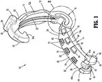
FIG. 1 is a side perspective view from a distal end of an exemplary embodiment of the presently disclosed ligation clip in an open position; -
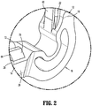
FIG. 2 is an enlarged view of the indicated area of detail shown inFIG. 1 -
FIG. 3 is side view of the ligation clip shown inFIG. 1 in the open position; -
FIG. 4 is side view of the ligation clip shown inFIG. 3 in the clamped position; -
FIG. 4A is a top view of the ligation clip shown inFIG. 4 in the clamped position; -
FIG. 5 is an enlarged view of the indicated area of detail shown inFIG. 3 ; -
FIG. 5A is an enlarged view of a hinge of a Prior Art ligation clip; and -
FIG. 6 is an enlarged view of the indicated area of detail shown inFIG. 4 . - The presently disclosed ligation clip will now be described in detail with reference to the drawings in which like reference numerals designate identical or corresponding elements in each of the several views. It is to be understood that the disclosed embodiments are merely exemplary of the disclosure and may be embodied in various forms. Well-known functions or constructions are not described in detail to avoid obscuring the present disclosure in unnecessary detail. Specific structural and functional details disclosed herein are not to be interpreted as limiting, but merely as a basis for the claims and as a representative basis for teaching one skilled in the art to variously employ the present disclosure in virtually any appropriately detailed structure.
- In this description, the term "proximal" is used generally to refer to that portion of the device that is closer to a clinician, while the term "distal" is used generally to refer to that portion of the device that is farther from the clinician. In addition, the term "clinician" is used generally to refer to medical personnel including doctors, nurses, and support personnel.
- Referring to
FIGS. 1-4A , an exemplary embodiment of the presently disclosed ligation clip is shown generally asligation clip 10. Theligation clip 10 includes afirst jaw 12, asecond jaw 14, and ahinge 16 coupling thefirst jaw 12 to thesecond jaw 14. Thefirst jaw 12 is pivotable in relation to thesecond jaw 14 about thehinge 16 to move theligation clip 10 between an open position (FIG. 1 ) and a clamped position (FIG. 4 ). In the clamped position, the first andsecond jaws FIG. 4A ). In embodiments, the first andsecond jaws FIG. 4 ) although other jaw configurations are envisioned. In embodiments, thehinge 16 is a living hinge that is integrally formed with proximal portions of the first andsecond jaws - The
first jaw 12 has abody 12a having aproximal portion 18, adistal portion 20, and a clampingsurface 22. Thesecond jaw 14 has abody 14a having aproximal portion 24, adistal portion 26, and a clampingsurface 28. Theproximal portions second jaws hinge 16 such that theligation clip 10 can pivot between the open position (FIG. 1 ) and the clamped position (FIG. 4 ). Thedistal portion 20 of thefirst jaw 12 includes afirst locking element 30 and spacedbosses 32. Thefirst locking element 30 includes a hookedportion 30a that extends downwardly and proximally from thetissue clamping surface 22 to define a portion of a latching mechanism 34 (FIG. 4 ) that is configured to retain theligation clip 10 in the clamped position as described in further detail below. - Each of the spaced
bosses 32 of thefirst jaw 12 extends outwardly of thebody 12a. In embodiments, the spacedbosses 32 are integrally formed as a single transverse member 36 (FIG. 1 ) that is supported on thedistal portion 20 of thefirst jaw 12. Thetransverse member 36 can be cylindrical although other configurations are envisioned. Thebosses 32 extend outwardly from thebody 12a of thefirst jaw 12 and are positioned and configured to be received within slots (not shown) formed in jaws of a clip applicator (not shown) to retain theligation clip 10 on the clip applicator. - The
second jaw 14 includes abody 14a. Thedistal portion 26 of thebody 14a of thesecond jaw 14 includes asecond locking element 40, spacedbosses 42, and spacedteeth 44. The spacedteeth 44 are configured to engage and/or penetrate tissue. In embodiments, each of theteeth 44 has an apex or pointedend 44a that grips and stretches tissue as theligation clip 10 is moved from the open position (FIG. 1 ) towards the clamped position (FIG. 4 ) to improve the ligating characteristics of theligation clip 10. Thesecond locking element 40 defines a cam surface 48 (FIG. 1 ) that is configured to receive and guide thefirst locking element 30 into locking engagement with thesecond locking element 40 when theligation clip 10 is moved to the clamped position (FIG. 4 ) to secure theligation clip 10 in the clamped position. In particular, thecam surface 48 is configured to deflect thefirst locking element 30 outwardly in a distal direction as thefirst locking element 30 passes over thecam surface 48 such that when thefirst locking element 30 moves past thecam surface 48, thefirst locking element 30 resiliently moves into engagement with thesecond locking element 40. - The
bosses 42 of thesecond jaw 14 are similar to thebosses 32 of thefirst jaw 12. More specifically, each of the spacedbosses 42 extends outwardly of thebody 14a of thesecond jaw 14 and is positioned to be received within slots (not shown) formed in jaws of a clip applicator (not shown) to retain theligation clip 10 on the clip applicator. - The
second jaw 14 includes aspring arm 56 that is positioned to engage thefirst locking element 30 when theligation element 10 is moved to the clamped position to retain thefirst locking element 30 and thesecond locking element 40 in the latched position (FIG. 4 ). Thespring arm 56 is positioned to engage and be deflected by thefirst locking element 30 to create a compressive force within thespring arm 56 that presses against thesecond locking element 40. - In embodiments, each of the first and second clamping surfaces 22, 28 of the first and
second jaws ligation clip 10 from sliding along tissue while theligation clip 10 is in the clamped position about the tissue. In embodiments, the clampingsurface 22 of thefirst jaw 12 may include alongitudinal rib 60 that extends along all or a portion of the length of the clampingsurface 22. In embodiments, thesecond clamping surface 28 of thesecond jaw 14 may also include a series offirst protrusions 62 that are positioned along one side of the clampingsurface 28 of thesecond jaw 14 and a series ofsecond protrusions 64 that are formed along an opposite side of thesecond clamping surface 28 of thesecond jaw 14. In some embodiments, thefirst protrusions 62 are spaced from thesecond protrusions 64 to define an unobstructed channel that receives thelongitudinal rib 60 when theligation clip 10 is in the clamped position. In embodiments, theprotrusions FIG. 2 ), a flattop wall 72, and an inner wall having avertical portion 74, and a taperedportion 76. In certain embodiments, thefirst protrusions 62 are axially offset from thesecond protrusions 64 such that the first andsecond protrusions second clamping surface 28. - Referring to
FIGS. 5-6 , thehinge 16 includes aninner hinge portion 80 and anouter hinge portion 82. Theinner hinge portion 80 includes aninner surface 84 that is contiguous with the first and second clamping surfaces 22, 28 of the first andsecond jaws outer surface 86. Theouter hinge portion 82 includes aninner surface 88 and anouter surface 90. Theouter surface 86 of theinner hinge portion 80 and theinner surface 88 of theouter hinge portion 82 define acavity 92 within thehinge 16. Theouter surface 90 of theouter hinge portion 82 is contiguous withouter surfaces second jaws ligation clip 10. - In the open position of the ligation clip 10 (
FIG. 5 ), theouter surface 86 of theinner hinge portion 80 includes a plurality of different curved sections. More specifically, theouter surface 86 of theinner hinge portion 80 includes a centralconvex section 100 that is bounded byconcave sections 102. Similarly, theinner surface 84 of theinner hinge portion 80 includes a plurality of curved sections including a centralconcave section 104 that is bounded byconvex sections 106. In embodiments, theconvex sections 106 are contiguous with the clamping surfaces 22, 28 of the first andsecond jaws ligation clip 10. In some embodiments, theinner hinge portion 80 has a substantially uniform thickness between theconcave sections 102 and theconvex sections 106 of theinner hinge portion 80. - In the open position of the
ligation clip 10, theouter surface 90 of theouter hinge portion 82 also defines aconvex section 110 that is bounded by less pronouncedconcave sections 112. In contrast, theinner surface 88 of theouter hinge portion 82 defines a single arcuate surface. - Referring to
FIG. 5A , in contrast to thehinge 16 of the presently disclosedligation clip 10, thehinge 216 of known ligation clips 200 includes aninner hinge portion 280 that has inner andouter surfaces hinge 216 also includes anouter hinge portion 282 that has inner andouter surfaces - Referring to
FIG. 6 , when theligation clip 10 is moved to the clamped position, the configuration of theinner hinge 80 and to a lesser extent, theouter hinge portion 82, reduces the stress or strain in thehinge 16 as theligation clip 10 is moved between the open and clamped position as compared to the stress or strain in known ligation clips, e.g.,clip 200. As such, theligation clip 10 is more capable of repeated movement between the open position and the clamped positions without fracturing and/or comprising the structural integrity of theligation clip 10. - In embodiments, the
surgical ligation clip 10 may be made, in whole or in part, of a resilient bioabsorbable and/or biocompatible polymeric material. Examples of suitable bioabsorbable and/or biocompatible polymers include acetal polyoxymethylene (POM), polyethylene terephthalate (PET), polybutylene terephthalate (PBT), polyoxymethylene, polyetheretherketone (PEEK), polypropylene, and polyethylene or other thermoplastic materials having similar properties that can be injection-molded. The clip may also be made of a polymer material or materials in combination with radiolucent metal alloys. Alternately, other materials may be used to form theclip 10 including biocompatible metals, plastics and composites. - Persons skilled in the art will understand that the devices and methods specifically described herein and illustrated in the accompanying drawings are non-limiting exemplary embodiments. It is envisioned that the elements and features illustrated or described in connection with one exemplary embodiment may be combined with the elements and features of another without departing from the scope of the present disclosure. As well, one skilled in the art will appreciate further features and advantages of the disclosure based on the above-described embodiments. Accordingly, the disclosure is not to be limited by what has been particularly shown and described, except as indicated by the appended claims.
- The invention may be described by reference to the following numbered paragraphs:-
- 1. A ligation clip comprising:
- a first jaw including a body having an inner surface defining a first clamping surface and an outer surface;
- a second jaw including a body having an inner surface defining a second clamping surface and an outer surface; and
- a hinge integrally formed with the first and second jaws, the hinge including an inner hinge portion and an outer hinge portion, the inner hinge portion having an inner surface that is contiguous with the first and second clamping surfaces of the first and second jaws and an outer surface, the hinge being configured to facilitate pivotal movement of the first jaw in relation to the second jaw between an open position and a clamped position;
- wherein the inner surface of the inner hinge portion is defined by a plurality of curved sections.
- 2. The ligation clip of paragraph 1, wherein the plurality of curved sections includes a concave section and two convex sections.
- 3. The ligation clip of
paragraph 2, wherein the concave section is bounded by the two convex sections. - 4. The ligation clip of paragraph 3, wherein the outer surface of the inner hinge includes a central convex section that is bounded by two concave sections.
- 5. The ligation clip of paragraph 3, wherein the inner hinge portion has a thickness that is uniform between the two convex sections.
- 6. The ligation clip of paragraph 1, wherein the outer hinge portion includes an inner surface and an outer surface, the inner surface of the outer hinge portion and the outer surface of the inner hinge portion defining a cavity in the hinge.
- 7. The ligation clip of
paragraph 6, wherein the outer surface of the outer hinge portion includes a central concave section that is bounded by two convex sections. - 8. The ligation clip of paragraph 1, wherein the first jaw includes a longitudinal rib having a tissue engaging surface that is positioned in opposition to the second clamping surface of the second jaw when the ligation clip is in the clamped position.
- 9. The ligation clip of paragraph 8, wherein the second jaw has a first row of protrusions supported on one side of the second clamping surface and a second row of protrusions supported on an opposite side of the second clamping surface, each of the protrusions of the first and second rows of protrusions having an inner side wall in opposition to the longitudinal rib when the ligation clip is in the clamped position.
- 10. The ligation clip of paragraph 9, wherein the inner side wall of each of the protrusions of the first and second rows of protrusions is angled towards the second clamping surface.
- 11. The ligation clip of
paragraph 10, wherein the first row of protrusions is laterally spaced from the second row of protrusions to define a channel that extends longitudinally between the first and second rows of protrusions, the channel being positioned to receive the longitudinal rib when the ligation clip is in the clamped position. - 12. The ligation clip of paragraph 9, wherein the protrusions in the first row of protrusions are longitudinally aligned and spaced from each other and the protrusions in the second row of protrusions are longitudinally aligned and spaced from each other.
- 13. The ligation clip of
paragraph 12, wherein each of the protrusions in the first row of protrusions is longitudinally offset from the protrusions in the second row of protrusions such that the protrusions in the first and second rows of protrusions are alternatingly positioned on opposite sides of the second clamping surface along at least a portion of the length of the second clamping surface. - 14. The ligation clip of paragraph 1, wherein the first jaw includes a first locking element and the second jaw includes a second locking element, the first locking element being movable into engagement with the second locking element to retain the ligation clip in the clamped position.
- 15. The ligation clip of
paragraph 14, wherein the first locking element includes a hooked portion that extends downwardly and proximally from the first tissue clamping surface and the second locking element is configured to engage the hooked portion. - 16. The ligation clip of paragraph 15, wherein the second locking element defines a cam surface that engages the hooked portion to bias the hooked portion outwardly of the second locking element such that the hooked portion resiliently returns to an unbiased state after passing over the second locking element to position the hooked portion in contact with the engagement surface.
- 17. The ligation clip of paragraph 1, wherein the ligation clip is formed of a polymeric material.
- 18. The ligation clip of paragraph 1, wherein the second jaw includes a distal portion, the distal portion including spaced teeth that are configured to engage tissue.
- 19. The ligation clip of
paragraph 18, wherein each of the spaced teeth has an apex that is configured to grip and stretch tissue as the ligation clip is moved to the clamped position. - 20. The ligation clip of
paragraph 16, wherein the second jaw includes a spring arm that is positioned to engage and be deflected by the first locking element as the ligation clip is moved from the open position to the clamped position, the spring arm being positioned to urge the first and second locking elements to a latched position.
Claims (15)
- A ligation clip comprising:a first jaw including a body having an inner surface defining a first clamping surface and an outer surface;a second jaw including a body having an inner surface defining a second clamping surface and an outer surface; anda hinge integrally formed with the first and second jaws, the hinge including an inner hinge portion and an outer hinge portion, the inner hinge portion having an inner surface that is contiguous with the first and second clamping surfaces of the first and second jaws and an outer surface, the hinge being configured to facilitate pivotal movement of the first jaw in relation to the second jaw between an open position and a clamped position;wherein the inner surface of the inner hinge portion is defined by a plurality of curved sections.
- The ligation clip of claim 1, wherein the plurality of curved sections includes a concave section and two convex sections; preferably wherein the concave section is bounded by the two convex sections.
- The ligation clip of claim 2, wherein the outer surface of the inner hinge includes a central convex section that is bounded by two concave sections; and/or wherein the inner hinge portion has a thickness that is uniform between the two convex sections.
- The ligation clip of any preceding claim, wherein the outer hinge portion includes an inner surface and an outer surface, the inner surface of the outer hinge portion and the outer surface of the inner hinge portion defining a cavity in the hinge; preferably wherein the outer surface of the outer hinge portion includes a central concave section that is bounded by two convex sections.
- The ligation clip of any preceding claim, wherein the first jaw includes a longitudinal rib having a tissue engaging surface that is positioned in opposition to the second clamping surface of the second jaw when the ligation clip is in the clamped position; preferably wherein the second jaw has a first row of protrusions supported on one side of the second clamping surface and a second row of protrusions supported on an opposite side of the second clamping surface, each of the protrusions of the first and second rows of protrusions having an inner side wall in opposition to the longitudinal rib when the ligation clip is in the clamped position.
- The ligation clip of claim 5, wherein the inner side wall of each of the protrusions of the first and second rows of protrusions is angled towards the second clamping surface; preferably wherein the first row of protrusions is laterally spaced from the second row of protrusions to define a channel that extends longitudinally between the first and second rows of protrusions, the channel being positioned to receive the longitudinal rib when the ligation clip is in the clamped position.
- The ligation clip of claim 6, wherein the protrusions in the first row of protrusions are longitudinally aligned and spaced from each other and the protrusions in the second row of protrusions are longitudinally aligned and spaced from each other.
- The ligation clip of claim 7, wherein each of the protrusions in the first row of protrusions is longitudinally offset from the protrusions in the second row of protrusions such that the protrusions in the first and second rows of protrusions are alternatingly positioned on opposite sides of the second clamping surface along at least a portion of the length of the second clamping surface.
- The ligation clip of any preceding claim, wherein the first jaw includes a first locking element and the second jaw includes a second locking element, the first locking element being movable into engagement with the second locking element to retain the ligation clip in the clamped position.
- The ligation clip of claim 19, wherein the first locking element includes a hooked portion that extends downwardly and proximally from the first tissue clamping surface and the second locking element is configured to engage the hooked portion.
- The ligation clip of claim 10, wherein the second locking element defines a cam surface that engages the hooked portion to bias the hooked portion outwardly of the second locking element such that the hooked portion resiliently returns to an unbiased state after passing over the second locking element to position the hooked portion in contact with the engagement surface.
- The ligation clip of any preceding claim, wherein the ligation clip is formed of a polymeric material.
- The ligation clip of any preceding claim, wherein the second jaw includes a distal portion, the distal portion including spaced teeth that are configured to engage tissue.
- The ligation clip of claim 13, wherein each of the spaced teeth has an apex that is configured to grip and stretch tissue as the ligation clip is moved to the clamped position.
- The ligation clip of any of claims 10 to 14, wherein the second jaw includes a spring arm that is positioned to engage and be deflected by the first locking element as the ligation clip is moved from the open position to the clamped position, the spring arm being positioned to urge the first and second locking elements to a latched position.
Applications Claiming Priority (2)
| Application Number | Priority Date | Filing Date | Title |
|---|---|---|---|
| US201862717958P | 2018-08-13 | 2018-08-13 | |
| US16/432,984 US11317923B2 (en) | 2018-08-13 | 2019-06-06 | Ligation clip with improved hinge |
Publications (2)
| Publication Number | Publication Date |
|---|---|
| EP3610804A1 true EP3610804A1 (en) | 2020-02-19 |
| EP3610804B1 EP3610804B1 (en) | 2023-07-12 |
Family
ID=67614472
Family Applications (1)
| Application Number | Title | Priority Date | Filing Date |
|---|---|---|---|
| EP19191228.6A Active EP3610804B1 (en) | 2018-08-13 | 2019-08-12 | Ligation clip with improved hinge |
Country Status (5)
| Country | Link |
|---|---|
| US (2) | US11317923B2 (en) |
| EP (1) | EP3610804B1 (en) |
| JP (1) | JP7369554B2 (en) |
| CN (1) | CN110811743A (en) |
| AU (1) | AU2019204426A1 (en) |
Cited By (1)
| Publication number | Priority date | Publication date | Assignee | Title |
|---|---|---|---|---|
| EP3552560B1 (en) * | 2018-04-11 | 2025-12-31 | Covidien LP | Ligature clamp with locking and holding features |
Families Citing this family (26)
| Publication number | Priority date | Publication date | Assignee | Title |
|---|---|---|---|---|
| US8465502B2 (en) | 2008-08-25 | 2013-06-18 | Covidien Lp | Surgical clip applier and method of assembly |
| US9358015B2 (en) | 2008-08-29 | 2016-06-07 | Covidien Lp | Endoscopic surgical clip applier with wedge plate |
| US8403945B2 (en) | 2010-02-25 | 2013-03-26 | Covidien Lp | Articulating endoscopic surgical clip applier |
| US8968337B2 (en) | 2010-07-28 | 2015-03-03 | Covidien Lp | Articulating clip applier |
| CA2958160A1 (en) | 2016-02-24 | 2017-08-24 | Covidien Lp | Endoscopic reposable surgical clip applier |
| US10492795B2 (en) | 2016-11-01 | 2019-12-03 | Covidien Lp | Endoscopic surgical clip applier |
| US11583291B2 (en) | 2017-02-23 | 2023-02-21 | Covidien Lp | Endoscopic surgical clip applier |
| US10675043B2 (en) | 2017-05-04 | 2020-06-09 | Covidien Lp | Reposable multi-fire surgical clip applier |
| CN110831521B (en) | 2017-06-22 | 2023-03-31 | 泰利福医疗公司 | Surgical clip |
| US11376015B2 (en) | 2017-11-03 | 2022-07-05 | Covidien Lp | Endoscopic surgical clip applier and handle assemblies for use therewith |
| US20190133590A1 (en) * | 2017-11-03 | 2019-05-09 | Covidien Lp | Ligation clip with controlled tissue compression |
| CN117357190A (en) | 2017-11-14 | 2024-01-09 | 泰利福医疗公司 | surgical clip |
| WO2020102700A1 (en) * | 2018-11-16 | 2020-05-22 | Telelflex Medical Incorporated | Surgical clip |
| USD907203S1 (en) * | 2019-08-02 | 2021-01-05 | Covidien Lp | Ligation clip |
| USD907204S1 (en) * | 2019-08-02 | 2021-01-05 | Covidien Lp | Ligation clip |
| USD907200S1 (en) * | 2019-08-05 | 2021-01-05 | Covidien Lp | Ligation clip |
| EP4076216A1 (en) | 2019-12-19 | 2022-10-26 | Teleflex Medical Incorporated | Surgical clip |
| US11779340B2 (en) | 2020-01-02 | 2023-10-10 | Covidien Lp | Ligation clip loading device |
| WO2021193463A1 (en) | 2020-03-24 | 2021-09-30 | 学校法人自治医科大学 | Medical instrument suitable for ligature or similar |
| US12114866B2 (en) | 2020-03-26 | 2024-10-15 | Covidien Lp | Interoperative clip loading device |
| EP4740877A2 (en) | 2021-05-07 | 2026-05-13 | Teleflex Medical LLC | Device for unlatching a surgical clip |
| KR102705086B1 (en) * | 2022-01-26 | 2024-09-11 | 주식회사 티플랜트 | Medical ligation clips |
| USD1031426S1 (en) * | 2022-07-27 | 2024-06-18 | Green Manatee, LLC | Holder |
| CN116869601A (en) * | 2023-06-29 | 2023-10-13 | 苏州英途康医疗科技有限公司 | A ligation clip and clamping device |
| CN117731356A (en) * | 2023-12-27 | 2024-03-22 | 苏州东昊塑胶五金有限公司 | Novel clip for blocking vascular tissue in surgery |
| US20260000408A1 (en) * | 2024-06-28 | 2026-01-01 | Ethicon, Inc. | Surgical clip requiring minimal closure force |
Citations (9)
| Publication number | Priority date | Publication date | Assignee | Title |
|---|---|---|---|---|
| EP0314064A2 (en) * | 1987-10-26 | 1989-05-03 | Pilling Weck Incorporated | Plastic ligating clips |
| US20050165423A1 (en) * | 2004-01-23 | 2005-07-28 | Pilling Weck Incorporated | Ligating clip with integral tissue-securing mechanism |
| EP2074954A1 (en) * | 2007-12-31 | 2009-07-01 | Teleflex Medical Incorporated | Ligation clip with flexible clamping feature |
| US20100211080A1 (en) * | 2009-02-13 | 2010-08-19 | Dean Trivisani | Umbiliguard |
| DE202010008714U1 (en) * | 2010-10-04 | 2010-12-02 | Aesculap Ag | Surgical clip |
| WO2013040306A1 (en) * | 2010-03-09 | 2013-03-21 | Teleflex Medical Incorporated | Narrow profile surgical ligation clip |
| US9220507B1 (en) * | 2012-10-14 | 2015-12-29 | Manoj B. Patel | Tissue spreading vascular clips with locking mechanism and non-slip clamping surfaces |
| EP3552560A1 (en) * | 2018-04-11 | 2019-10-16 | Covidien LP | Ligation clip with latching and retention features |
| EP3572012A1 (en) * | 2018-05-25 | 2019-11-27 | Covidien LP | Ligation clip removal device |
Family Cites Families (129)
| Publication number | Priority date | Publication date | Assignee | Title |
|---|---|---|---|---|
| US3439523A (en) | 1964-03-30 | 1969-04-22 | Peter B Samuels | Hemostatic clip constructions |
| BE654195A (en) | 1964-10-09 | 1965-02-01 | ||
| US3713533A (en) | 1971-04-28 | 1973-01-30 | Codman & Shurtleff | Hemostatic clip holder |
| US4076120A (en) | 1976-12-10 | 1978-02-28 | American Hospital Supply Corporation | Cartridge for holding hemostatic clips |
| US4146130A (en) | 1977-04-08 | 1979-03-27 | Samuels Peter B | Hemostatic clip, clip applicator and cartridge therefor |
| US4187712A (en) | 1977-04-08 | 1980-02-12 | Samuels Peter B | Hemostatic clip applicator |
| US4212390A (en) | 1977-10-20 | 1980-07-15 | Propper Manufacturing Co., Inc. | Wound clip rack |
| US4212303A (en) | 1978-07-17 | 1980-07-15 | Hollister Incorporated | Umbilical cord clamp |
| US4390019A (en) | 1979-02-28 | 1983-06-28 | Leveen Harry H | Blood vessel clamp |
| US4418694A (en) | 1979-06-18 | 1983-12-06 | Ethicon, Inc. | Non-metallic, bio-compatible hemostatic clips |
| US4294355A (en) | 1979-12-06 | 1981-10-13 | Ethicon, Inc. | Cartridge for hemostatic clips |
| US4344531A (en) | 1980-09-08 | 1982-08-17 | Edward Weck & Company, Inc. | Hemostatic clip cartridge |
| US4346869A (en) | 1981-03-12 | 1982-08-31 | Macneill Robert L | Tube clamp |
| US4412617A (en) | 1981-07-20 | 1983-11-01 | Ethicon, Inc. | Ligating clip package |
| US4361229A (en) | 1981-08-03 | 1982-11-30 | Ethicon, Inc. | Cartridge for hemostatic clips |
| US4449531A (en) | 1981-08-27 | 1984-05-22 | Ethicon, Inc. | Non-metallic, bio-compatible hemostatic clips with interlocking latch means |
| US4550729A (en) | 1981-08-27 | 1985-11-05 | Ethicon, Inc. | Non-metallic, bio-compatible hemostatic clips with interlocking latch means |
| US4485953A (en) | 1982-04-05 | 1984-12-04 | Senco Products, Inc. | Surgical stapling instrument and cartridge therefor |
| US4487205A (en) | 1982-04-26 | 1984-12-11 | Ethicon, Inc. | Non-metallic, bio-compatible hemostatic clips |
| US4696396A (en) | 1985-12-19 | 1987-09-29 | Samuels Peter B | Hemostatic clip cartridge |
| US4726372A (en) | 1986-09-19 | 1988-02-23 | Metatech Corporation | Hemostatic clip |
| US4971198A (en) | 1988-04-18 | 1990-11-20 | Edward Weck Incorporated | Hemostatic clip and cartridge assembly |
| US4942886A (en) | 1989-02-22 | 1990-07-24 | Timmons John W | External incontinency device |
| US5062846A (en) | 1989-03-28 | 1991-11-05 | Edward Weck Incorporated | Penetrating plastic ligating clip |
| US4936447A (en) | 1989-09-26 | 1990-06-26 | Horizon Surgical Inc. | Hemostatic clip holder |
| US4972949A (en) | 1989-09-26 | 1990-11-27 | Horizon Surgical, Inc. | Hemostatic clip holder for small clips |
| US5100416A (en) | 1989-10-17 | 1992-03-31 | Edward Weck Incorporated | Ligating clip applying instrument |
| US4961499A (en) | 1990-01-04 | 1990-10-09 | Pilling Co. | Hemostatic clip cartridge |
| US5046624A (en) | 1990-08-13 | 1991-09-10 | Murphy Susan A | Surgical instrument stand |
| US5050272A (en) | 1990-10-16 | 1991-09-24 | Anago, Inc. | Closure member for an ice bag |
| US5046611A (en) | 1990-10-22 | 1991-09-10 | Edward Weck Incorporated | Hemostatic clip cartridge |
| US5201416A (en) | 1990-10-22 | 1993-04-13 | Edward Weck Incorporated | Hemostatic clip cartridge |
| US5423831A (en) | 1991-01-24 | 1995-06-13 | Nates; Colin | Clamp |
| US5279416A (en) | 1992-06-05 | 1994-01-18 | Edward Weck Incorporated | Ligating device cartridge with separable retainer |
| US5234449A (en) * | 1992-07-16 | 1993-08-10 | Ethicon, Inc. | Suture clip with reduced hinge mass |
| US5403327A (en) | 1992-12-31 | 1995-04-04 | Pilling Weck Incorporated | Surgical clip applier |
| US5697942A (en) | 1994-07-31 | 1997-12-16 | Palti; Yoram | Internal vascular clamp |
| US5908430A (en) | 1995-06-07 | 1999-06-01 | Appleby; Timothy | Easy loading hemostatic clip and cartridge |
| US5564262A (en) | 1995-07-20 | 1996-10-15 | Ethicon, Inc. | Ligaclip loading machine and process |
| US5713912A (en) | 1995-08-30 | 1998-02-03 | Stress Management, Inc. | Ligating clip having ramp-shaped vessel clamping members and tool for applying same |
| US5676676A (en) | 1995-08-30 | 1997-10-14 | Porter; Wayne | Ligating clip having ramp-shaped vessel-clamping members |
| US5846255A (en) | 1996-01-31 | 1998-12-08 | Casey Medical Products Limited | Surgical clip |
| FR2751863B1 (en) | 1996-08-01 | 1999-01-22 | Vitalitec International | HEMOSTATIC CLIPS SUPPORT |
| GB9707204D0 (en) | 1997-04-09 | 1997-05-28 | Price Invena Aps | Clamping and cutting devices |
| US6044971A (en) | 1997-10-10 | 2000-04-04 | United States Surgical Corporation | Clip cartridge |
| US5921991A (en) | 1997-10-23 | 1999-07-13 | Biomax Technologies Inc. | Multi-colored umbilical cord clamp |
| US5938666A (en) * | 1998-03-27 | 1999-08-17 | University Of Western Ontario | Umbilical cord clamp |
| US6609522B2 (en) * | 1998-04-28 | 2003-08-26 | Uroscientific Incorporated | Urethral compression device |
| JP2000131620A (en) | 1998-10-27 | 2000-05-12 | Olympus Optical Co Ltd | Telescope |
| US6228097B1 (en) | 1999-01-22 | 2001-05-08 | Scion International, Inc. | Surgical instrument for clipping and cutting blood vessels and organic structures |
| US6217590B1 (en) | 1999-01-22 | 2001-04-17 | Scion International, Inc. | Surgical instrument for applying multiple staples and cutting blood vessels and organic structures and method therefor |
| DE19903752C1 (en) | 1999-01-30 | 2000-03-30 | Aesculap Ag & Co Kg | Clip magazine for haemostatic medical clip driver has independent actuated clamps for arms and bases of clips |
| GB2353710A (en) | 1999-08-06 | 2001-03-07 | Henleys Medical Supplies Ltd | Umbilical cord clamp |
| IL132913A (en) | 1999-11-14 | 2004-09-27 | Porat Michael | Device and method for clamping and cutting a flexible deformable tube |
| US6391035B1 (en) | 2000-03-24 | 2002-05-21 | Timothy Appleby | Hemostatic clip removal instrument |
| US6419682B1 (en) | 2000-03-24 | 2002-07-16 | Timothy Appleby | Hemostatic clip cartridge |
| US6349727B1 (en) | 2000-05-25 | 2002-02-26 | Pos-T-Vac, Inc. | Penile clamp for inhibiting incontinence |
| US6273253B1 (en) | 2000-07-07 | 2001-08-14 | Vitalitec International, Inc. | Cartridge and system for holding and applying clips |
| US20020046961A1 (en) | 2000-10-19 | 2002-04-25 | Scion International | Surgical clip holder and method therefor |
| DE10116168A1 (en) | 2001-03-31 | 2001-11-29 | Joachim Heinzl | Clip has gripper arms operated by articulated lever mechanism and joined by spacer piece, tie rod, pulley cable, locking mechanism with cogging and pawl |
| US20020177863A1 (en) | 2001-05-24 | 2002-11-28 | Mandel Stanley R. | Surface treated ligating clip |
| US6824547B2 (en) | 2001-07-13 | 2004-11-30 | Pilling Weck Incorporated | Endoscopic clip applier and method |
| US7094245B2 (en) * | 2001-10-05 | 2006-08-22 | Scimed Life Systems, Inc. | Device and method for through the scope endoscopic hemostatic clipping |
| US20030069589A1 (en) | 2001-10-09 | 2003-04-10 | Small George H. | Umbilical cord clamp and methods of using same |
| US20040199178A1 (en) | 2001-10-09 | 2004-10-07 | Small George H. | Umbilical cord clamp and methods of using same |
| US7131977B2 (en) | 2002-08-27 | 2006-11-07 | Pilling Weck Incorporated | Apparatus and method for removing a clip |
| US7211091B2 (en) * | 2002-08-27 | 2007-05-01 | Pilling Weck Incorporated | Fingertip-actuated surgical clip applier and related methods |
| US6880699B2 (en) | 2002-08-27 | 2005-04-19 | Pilling Weck Incorporated | Cartridge for holding asymmetric surgical clips |
| US6863675B2 (en) | 2002-09-20 | 2005-03-08 | Pilling Weck Incorporated | Ligating clip with integral penetrating hook |
| US7211092B2 (en) | 2002-11-19 | 2007-05-01 | Pilling Weck Incorporated | Automated-feed surgical clip applier and related methods |
| US7052504B2 (en) | 2002-11-19 | 2006-05-30 | Teleflex Incorporated | Automated-feed surgical clip applier and related methods |
| EP3170459A1 (en) | 2003-03-11 | 2017-05-24 | Covidien LP | Clip applying apparatus with angled jaw |
| US7144402B2 (en) | 2003-06-16 | 2006-12-05 | Synovis Life Technologies, Inc. | Vascular clamp |
| US7326223B2 (en) * | 2004-01-22 | 2008-02-05 | Teleflex Medical Incorporated | Ligating clip with integral cutting guide |
| US7316696B2 (en) | 2004-01-22 | 2008-01-08 | Teleflex Medical Incorporated | Ligating clip with integral interlocking latch mechanism |
| US7001412B2 (en) * | 2004-01-28 | 2006-02-21 | Pilling Weck Incorporated | Surgical clip with integral suture-securing mechanism |
| US7585304B2 (en) | 2004-02-02 | 2009-09-08 | Teleflex Medical Incorporated | Endoscopic clip applying apparatus with improved aperture for clip release and related method |
| NZ550345A (en) | 2004-03-07 | 2009-11-27 | Synthes Gmbh | Container and carrier system for holding and presenting surgical materials such as bone screws |
| US7452368B2 (en) | 2004-09-15 | 2008-11-18 | Ethicon, Inc. | System for holding surgical fasteners |
| US20060124485A1 (en) | 2004-12-10 | 2006-06-15 | Kennedy Daniel L | Enhanced visibility cartridge with improved retainer |
| US20060217749A1 (en) | 2005-03-24 | 2006-09-28 | Pilling Weck Incorporated | Reduced closure force ligating clip |
| DE102005045006B3 (en) | 2005-09-21 | 2007-01-04 | Cardiomedical Gmbh | Case for haemostatic clamps for surgical use has bottom part containing pockets and bracket to hold clamp and top part with clamp parts to hold clamp securely in each clamp pocket |
| US20070083218A1 (en) | 2005-10-12 | 2007-04-12 | A Morris Steven | Coated ligating clip |
| US20070118161A1 (en) | 2005-11-22 | 2007-05-24 | Kennedy Daniel L | Non-snag polymer ligating clip |
| US9486225B2 (en) | 2005-12-22 | 2016-11-08 | Robert E. Michler | Exclusion of the left atrial appendage |
| US9480480B2 (en) | 2005-12-22 | 2016-11-01 | Albert N. Santilli | Vascular and intestinal occlusion |
| US8328458B2 (en) | 2007-07-20 | 2012-12-11 | Twin Bay Medical, Inc. | Sanitary clamp |
| US8042687B2 (en) | 2007-12-14 | 2011-10-25 | Vesocclude Medical Llc | Hemostatic clip cartridge |
| DE102008018158A1 (en) | 2008-04-10 | 2009-10-15 | Aesculap Ag | Ligature clip magazine and bearing body for use in this |
| DE102009035756A1 (en) | 2009-07-24 | 2011-01-27 | Aesculap Ag | Clip carrier device |
| US8425515B2 (en) | 2009-10-30 | 2013-04-23 | Depuy Spine, Inc. | Bone graft loading instruments and methods of connecting a bone graft to a bone plate |
| US10136898B2 (en) * | 2010-03-09 | 2018-11-27 | Teleflex Medical Incorporated | Narrow profile surgical ligation clip |
| JP5628348B2 (en) * | 2010-03-09 | 2014-11-19 | テレフレックス・メディカル・インコーポレイテッド | Narrow contour surgical ligation clip |
| US20110295291A1 (en) * | 2010-05-28 | 2011-12-01 | Dean Trivisani | Novel Vascular Clamp |
| US10335157B2 (en) | 2010-10-02 | 2019-07-02 | Covidien Lp | Asymmetrical surgical clip with penetrating lock, non-slip clamping surface, severable hinge, hinge boss and pivoting applicator tip |
| WO2012122006A2 (en) | 2011-03-04 | 2012-09-13 | Jenkins Clinic, Inc. | Surgical ligation clip and applicator device |
| CA2830073A1 (en) * | 2011-03-21 | 2012-09-27 | The Administrators Of The Tulane Educational Fund | Multi-component detachable jaw tools and methods of using and making same |
| KR20140015514A (en) | 2011-04-26 | 2014-02-06 | 바이탈리텍 인터내셔널, 아이엔씨. | Cartridge for surgical fasteners with integrated lock system |
| JP2014531248A (en) | 2011-09-15 | 2014-11-27 | テレフレックス メディカル インコーポレイテッドTeleflex Medical Incorporated | Automatic surgical ligation clip applier |
| JP5848827B2 (en) | 2011-09-15 | 2016-01-27 | テレフレックス メディカル インコーポレイテッドTeleflex Medical Incorporated | Manual surgical ligation clip applier |
| AU2012325718B2 (en) | 2011-10-20 | 2017-08-10 | Teleflex Life Sciences Llc | Ligation clip |
| DE102011056821A1 (en) | 2011-12-21 | 2013-06-27 | Aesculap Ag | Medical clip carrier device |
| US9282972B1 (en) * | 2012-10-14 | 2016-03-15 | Innovative Urololy, Llc | Surgical clips with penetrating locking mechanism and non-slip clamping surfaces |
| US9901351B2 (en) * | 2012-11-21 | 2018-02-27 | Atricure, Inc. | Occlusion clip |
| KR101377429B1 (en) | 2013-02-20 | 2014-03-26 | (주)유원메디텍 | A ligating clip for surgical operation |
| US10226273B2 (en) | 2013-03-14 | 2019-03-12 | Ethicon Llc | Mechanical fasteners for use with surgical energy devices |
| CN103919589A (en) * | 2014-03-10 | 2014-07-16 | 浙江微度医疗器械有限公司 | Anti-shedding hemostatic clamp |
| WO2016081822A1 (en) | 2014-11-21 | 2016-05-26 | Novate Medical Technologies, Llc | Multi-component detachable cutting and clamping tool and methods of using same |
| CN106264647A (en) | 2015-06-04 | 2017-01-04 | 上海林超医疗设备科技有限公司 | There is out the Clip Applier of folder function |
| US10881414B2 (en) | 2015-06-16 | 2021-01-05 | Nanoya Biomaterials, Inc. | Anti-migration surgical ligation clip |
| CN204839635U (en) | 2015-06-19 | 2015-12-09 | 江西圣济药业有限公司 | Make bit -type umbilical cord clamps by oneself |
| EP3328295B1 (en) | 2015-07-30 | 2021-05-05 | Teleflex Medical Incorporated | Snap-on surgical clip cartridge |
| CN105078536A (en) * | 2015-08-26 | 2015-11-25 | 施青青 | Duplex tissue clip and clip applier |
| CN105105815B (en) * | 2015-10-02 | 2017-07-07 | 北京光辉天成医疗科技有限公司 | A kind of Medical ligation clip |
| US10258345B2 (en) | 2016-05-25 | 2019-04-16 | Geoff Brown | Surgical ligation clip |
| CA3032824C (en) | 2016-08-03 | 2021-04-27 | Teleflex Medical Incorporated | Surgical ligation clip |
| WO2018175651A1 (en) | 2017-03-21 | 2018-09-27 | Teleflex Medical Incorporated | Clip applier having stabilizing member |
| CN119112285A (en) | 2017-03-21 | 2024-12-13 | 泰利福医疗公司 | Flexible stabilizing member for clip applier |
| WO2018175605A1 (en) | 2017-03-21 | 2018-09-27 | Teleflex Medical Incorporated | Clip applier with replaceable tips |
| CN110740695B (en) | 2017-03-21 | 2024-10-25 | 泰利福医疗公司 | Surgical Clips and Clip Appliers |
| DE102017112896A1 (en) * | 2017-06-12 | 2018-12-13 | Ovesco Endoscopy Ag | Tissue clip application Ausrüst- / retrofit kit |
| CN110831521B (en) * | 2017-06-22 | 2023-03-31 | 泰利福医疗公司 | Surgical clip |
| USD808522S1 (en) | 2017-07-11 | 2018-01-23 | Vesolock Medical, Llc | Latching ends of a polymer ligating clip |
| US20190133590A1 (en) | 2017-11-03 | 2019-05-09 | Covidien Lp | Ligation clip with controlled tissue compression |
| US20190159782A1 (en) | 2017-11-28 | 2019-05-30 | Covidien Lp | Surgical ligation clip with tissue stop member |
| US20190223874A1 (en) | 2018-01-24 | 2019-07-25 | Covidien Lp | Ligation clip with tissue retention features |
| US10932788B2 (en) * | 2018-04-11 | 2021-03-02 | Covidien Lp | Ligation clip with latching and retention features |
| US11033279B2 (en) * | 2018-04-24 | 2021-06-15 | Covidien Lp | Ligation clip with retention features |
| US11304704B2 (en) * | 2018-08-22 | 2022-04-19 | Covidien Lp | Surgical clip applier and ligation clips |
-
2019
- 2019-06-06 US US16/432,984 patent/US11317923B2/en active Active
- 2019-06-24 AU AU2019204426A patent/AU2019204426A1/en not_active Abandoned
- 2019-07-11 JP JP2019129146A patent/JP7369554B2/en active Active
- 2019-08-05 CN CN201910717691.XA patent/CN110811743A/en active Pending
- 2019-08-12 EP EP19191228.6A patent/EP3610804B1/en active Active
-
2022
- 2022-04-04 US US17/712,292 patent/US20220225996A1/en active Pending
Patent Citations (9)
| Publication number | Priority date | Publication date | Assignee | Title |
|---|---|---|---|---|
| EP0314064A2 (en) * | 1987-10-26 | 1989-05-03 | Pilling Weck Incorporated | Plastic ligating clips |
| US20050165423A1 (en) * | 2004-01-23 | 2005-07-28 | Pilling Weck Incorporated | Ligating clip with integral tissue-securing mechanism |
| EP2074954A1 (en) * | 2007-12-31 | 2009-07-01 | Teleflex Medical Incorporated | Ligation clip with flexible clamping feature |
| US20100211080A1 (en) * | 2009-02-13 | 2010-08-19 | Dean Trivisani | Umbiliguard |
| WO2013040306A1 (en) * | 2010-03-09 | 2013-03-21 | Teleflex Medical Incorporated | Narrow profile surgical ligation clip |
| DE202010008714U1 (en) * | 2010-10-04 | 2010-12-02 | Aesculap Ag | Surgical clip |
| US9220507B1 (en) * | 2012-10-14 | 2015-12-29 | Manoj B. Patel | Tissue spreading vascular clips with locking mechanism and non-slip clamping surfaces |
| EP3552560A1 (en) * | 2018-04-11 | 2019-10-16 | Covidien LP | Ligation clip with latching and retention features |
| EP3572012A1 (en) * | 2018-05-25 | 2019-11-27 | Covidien LP | Ligation clip removal device |
Cited By (1)
| Publication number | Priority date | Publication date | Assignee | Title |
|---|---|---|---|---|
| EP3552560B1 (en) * | 2018-04-11 | 2025-12-31 | Covidien LP | Ligature clamp with locking and holding features |
Also Published As
| Publication number | Publication date |
|---|---|
| CN110811743A (en) | 2020-02-21 |
| US20220225996A1 (en) | 2022-07-21 |
| JP2020025856A (en) | 2020-02-20 |
| US20200046359A1 (en) | 2020-02-13 |
| JP7369554B2 (en) | 2023-10-26 |
| US11317923B2 (en) | 2022-05-03 |
| EP3610804B1 (en) | 2023-07-12 |
| AU2019204426A1 (en) | 2020-02-27 |
Similar Documents
| Publication | Publication Date | Title |
|---|---|---|
| US20220225996A1 (en) | Ligation clip with improved hinge | |
| US11304704B2 (en) | Surgical clip applier and ligation clips | |
| EP3552560B1 (en) | Ligature clamp with locking and holding features | |
| CN110063767B (en) | Ligating clip with tissue retaining feature | |
| US11033279B2 (en) | Ligation clip with retention features | |
| JP6815506B2 (en) | Clip treatment tool | |
| EP3488798A1 (en) | Surgical ligation clip with tissue stop member | |
| US20220047271A1 (en) | Clip applier with stabilizing member | |
| US12023041B2 (en) | Clip applier | |
| US10932788B2 (en) | Ligation clip with latching and retention features | |
| WO2019169580A1 (en) | Ligation clip with retention features | |
| EP3771439A1 (en) | Ligation clip with improved latch mechanism | |
| US12318094B2 (en) | Clip applier | |
| JP6858258B2 (en) | Clip treatment tool | |
| EP3771438A1 (en) | Two-piece ligation clip |
Legal Events
| Date | Code | Title | Description |
|---|---|---|---|
| PUAI | Public reference made under article 153(3) epc to a published international application that has entered the european phase |
Free format text: ORIGINAL CODE: 0009012 |
|
| STAA | Information on the status of an ep patent application or granted ep patent |
Free format text: STATUS: THE APPLICATION HAS BEEN PUBLISHED |
|
| AK | Designated contracting states |
Kind code of ref document: A1 Designated state(s): AL AT BE BG CH CY CZ DE DK EE ES FI FR GB GR HR HU IE IS IT LI LT LU LV MC MK MT NL NO PL PT RO RS SE SI SK SM TR |
|
| AX | Request for extension of the european patent |
Extension state: BA ME |
|
| STAA | Information on the status of an ep patent application or granted ep patent |
Free format text: STATUS: REQUEST FOR EXAMINATION WAS MADE |
|
| 17P | Request for examination filed |
Effective date: 20200810 |
|
| RBV | Designated contracting states (corrected) |
Designated state(s): AL AT BE BG CH CY CZ DE DK EE ES FI FR GB GR HR HU IE IS IT LI LT LU LV MC MK MT NL NO PL PT RO RS SE SI SK SM TR |
|
| GRAP | Despatch of communication of intention to grant a patent |
Free format text: ORIGINAL CODE: EPIDOSNIGR1 |
|
| STAA | Information on the status of an ep patent application or granted ep patent |
Free format text: STATUS: GRANT OF PATENT IS INTENDED |
|
| RIC1 | Information provided on ipc code assigned before grant |
Ipc: A61B 17/00 20060101ALN20230124BHEP Ipc: A61B 17/122 20060101AFI20230124BHEP |
|
| INTG | Intention to grant announced |
Effective date: 20230208 |
|
| RIC1 | Information provided on ipc code assigned before grant |
Ipc: A61B 17/00 20060101ALN20230127BHEP Ipc: A61B 17/122 20060101AFI20230127BHEP |
|
| GRAS | Grant fee paid |
Free format text: ORIGINAL CODE: EPIDOSNIGR3 |
|
| GRAA | (expected) grant |
Free format text: ORIGINAL CODE: 0009210 |
|
| STAA | Information on the status of an ep patent application or granted ep patent |
Free format text: STATUS: THE PATENT HAS BEEN GRANTED |
|
| AK | Designated contracting states |
Kind code of ref document: B1 Designated state(s): AL AT BE BG CH CY CZ DE DK EE ES FI FR GB GR HR HU IE IS IT LI LT LU LV MC MK MT NL NO PL PT RO RS SE SI SK SM TR |
|
| REG | Reference to a national code |
Ref country code: CH Ref legal event code: EP |
|
| REG | Reference to a national code |
Ref country code: IE Ref legal event code: FG4D |
|
| REG | Reference to a national code |
Ref country code: DE Ref legal event code: R096 Ref document number: 602019032436 Country of ref document: DE |
|
| REG | Reference to a national code |
Ref country code: LT Ref legal event code: MG9D |
|
| REG | Reference to a national code |
Ref country code: NL Ref legal event code: MP Effective date: 20230712 |
|
| REG | Reference to a national code |
Ref country code: AT Ref legal event code: MK05 Ref document number: 1586238 Country of ref document: AT Kind code of ref document: T Effective date: 20230712 |
|
| PG25 | Lapsed in a contracting state [announced via postgrant information from national office to epo] |
Ref country code: NL Free format text: LAPSE BECAUSE OF FAILURE TO SUBMIT A TRANSLATION OF THE DESCRIPTION OR TO PAY THE FEE WITHIN THE PRESCRIBED TIME-LIMIT Effective date: 20230712 |
|
| PG25 | Lapsed in a contracting state [announced via postgrant information from national office to epo] |
Ref country code: GR Free format text: LAPSE BECAUSE OF FAILURE TO SUBMIT A TRANSLATION OF THE DESCRIPTION OR TO PAY THE FEE WITHIN THE PRESCRIBED TIME-LIMIT Effective date: 20231013 |
|
| PG25 | Lapsed in a contracting state [announced via postgrant information from national office to epo] |
Ref country code: ES Free format text: LAPSE BECAUSE OF FAILURE TO SUBMIT A TRANSLATION OF THE DESCRIPTION OR TO PAY THE FEE WITHIN THE PRESCRIBED TIME-LIMIT Effective date: 20230712 |
|
| PG25 | Lapsed in a contracting state [announced via postgrant information from national office to epo] |
Ref country code: IS Free format text: LAPSE BECAUSE OF FAILURE TO SUBMIT A TRANSLATION OF THE DESCRIPTION OR TO PAY THE FEE WITHIN THE PRESCRIBED TIME-LIMIT Effective date: 20231112 |
|
| PG25 | Lapsed in a contracting state [announced via postgrant information from national office to epo] |
Ref country code: SE Free format text: LAPSE BECAUSE OF FAILURE TO SUBMIT A TRANSLATION OF THE DESCRIPTION OR TO PAY THE FEE WITHIN THE PRESCRIBED TIME-LIMIT Effective date: 20230712 Ref country code: RS Free format text: LAPSE BECAUSE OF FAILURE TO SUBMIT A TRANSLATION OF THE DESCRIPTION OR TO PAY THE FEE WITHIN THE PRESCRIBED TIME-LIMIT Effective date: 20230712 Ref country code: PT Free format text: LAPSE BECAUSE OF FAILURE TO SUBMIT A TRANSLATION OF THE DESCRIPTION OR TO PAY THE FEE WITHIN THE PRESCRIBED TIME-LIMIT Effective date: 20231113 Ref country code: NO Free format text: LAPSE BECAUSE OF FAILURE TO SUBMIT A TRANSLATION OF THE DESCRIPTION OR TO PAY THE FEE WITHIN THE PRESCRIBED TIME-LIMIT Effective date: 20231012 Ref country code: LV Free format text: LAPSE BECAUSE OF FAILURE TO SUBMIT A TRANSLATION OF THE DESCRIPTION OR TO PAY THE FEE WITHIN THE PRESCRIBED TIME-LIMIT Effective date: 20230712 Ref country code: LT Free format text: LAPSE BECAUSE OF FAILURE TO SUBMIT A TRANSLATION OF THE DESCRIPTION OR TO PAY THE FEE WITHIN THE PRESCRIBED TIME-LIMIT Effective date: 20230712 Ref country code: IS Free format text: LAPSE BECAUSE OF FAILURE TO SUBMIT A TRANSLATION OF THE DESCRIPTION OR TO PAY THE FEE WITHIN THE PRESCRIBED TIME-LIMIT Effective date: 20231112 Ref country code: HR Free format text: LAPSE BECAUSE OF FAILURE TO SUBMIT A TRANSLATION OF THE DESCRIPTION OR TO PAY THE FEE WITHIN THE PRESCRIBED TIME-LIMIT Effective date: 20230712 Ref country code: GR Free format text: LAPSE BECAUSE OF FAILURE TO SUBMIT A TRANSLATION OF THE DESCRIPTION OR TO PAY THE FEE WITHIN THE PRESCRIBED TIME-LIMIT Effective date: 20231013 Ref country code: FI Free format text: LAPSE BECAUSE OF FAILURE TO SUBMIT A TRANSLATION OF THE DESCRIPTION OR TO PAY THE FEE WITHIN THE PRESCRIBED TIME-LIMIT Effective date: 20230712 Ref country code: ES Free format text: LAPSE BECAUSE OF FAILURE TO SUBMIT A TRANSLATION OF THE DESCRIPTION OR TO PAY THE FEE WITHIN THE PRESCRIBED TIME-LIMIT Effective date: 20230712 Ref country code: AT Free format text: LAPSE BECAUSE OF FAILURE TO SUBMIT A TRANSLATION OF THE DESCRIPTION OR TO PAY THE FEE WITHIN THE PRESCRIBED TIME-LIMIT Effective date: 20230712 |
|
| PG25 | Lapsed in a contracting state [announced via postgrant information from national office to epo] |
Ref country code: PL Free format text: LAPSE BECAUSE OF FAILURE TO SUBMIT A TRANSLATION OF THE DESCRIPTION OR TO PAY THE FEE WITHIN THE PRESCRIBED TIME-LIMIT Effective date: 20230712 |
|
| REG | Reference to a national code |
Ref country code: CH Ref legal event code: PL |
|
| REG | Reference to a national code |
Ref country code: DE Ref legal event code: R097 Ref document number: 602019032436 Country of ref document: DE |
|
| PG25 | Lapsed in a contracting state [announced via postgrant information from national office to epo] |
Ref country code: LU Free format text: LAPSE BECAUSE OF NON-PAYMENT OF DUE FEES Effective date: 20230812 |
|
| PG25 | Lapsed in a contracting state [announced via postgrant information from national office to epo] |
Ref country code: SM Free format text: LAPSE BECAUSE OF FAILURE TO SUBMIT A TRANSLATION OF THE DESCRIPTION OR TO PAY THE FEE WITHIN THE PRESCRIBED TIME-LIMIT Effective date: 20230712 Ref country code: RO Free format text: LAPSE BECAUSE OF FAILURE TO SUBMIT A TRANSLATION OF THE DESCRIPTION OR TO PAY THE FEE WITHIN THE PRESCRIBED TIME-LIMIT Effective date: 20230712 Ref country code: LU Free format text: LAPSE BECAUSE OF NON-PAYMENT OF DUE FEES Effective date: 20230812 Ref country code: EE Free format text: LAPSE BECAUSE OF FAILURE TO SUBMIT A TRANSLATION OF THE DESCRIPTION OR TO PAY THE FEE WITHIN THE PRESCRIBED TIME-LIMIT Effective date: 20230712 Ref country code: DK Free format text: LAPSE BECAUSE OF FAILURE TO SUBMIT A TRANSLATION OF THE DESCRIPTION OR TO PAY THE FEE WITHIN THE PRESCRIBED TIME-LIMIT Effective date: 20230712 Ref country code: CZ Free format text: LAPSE BECAUSE OF FAILURE TO SUBMIT A TRANSLATION OF THE DESCRIPTION OR TO PAY THE FEE WITHIN THE PRESCRIBED TIME-LIMIT Effective date: 20230712 Ref country code: CH Free format text: LAPSE BECAUSE OF NON-PAYMENT OF DUE FEES Effective date: 20230831 Ref country code: SK Free format text: LAPSE BECAUSE OF FAILURE TO SUBMIT A TRANSLATION OF THE DESCRIPTION OR TO PAY THE FEE WITHIN THE PRESCRIBED TIME-LIMIT Effective date: 20230712 Ref country code: MC Free format text: LAPSE BECAUSE OF FAILURE TO SUBMIT A TRANSLATION OF THE DESCRIPTION OR TO PAY THE FEE WITHIN THE PRESCRIBED TIME-LIMIT Effective date: 20230712 |
|
| REG | Reference to a national code |
Ref country code: BE Ref legal event code: MM Effective date: 20230831 |
|
| PLBE | No opposition filed within time limit |
Free format text: ORIGINAL CODE: 0009261 |
|
| STAA | Information on the status of an ep patent application or granted ep patent |
Free format text: STATUS: NO OPPOSITION FILED WITHIN TIME LIMIT |
|
| REG | Reference to a national code |
Ref country code: IE Ref legal event code: MM4A |
|
| PG25 | Lapsed in a contracting state [announced via postgrant information from national office to epo] |
Ref country code: IT Free format text: LAPSE BECAUSE OF FAILURE TO SUBMIT A TRANSLATION OF THE DESCRIPTION OR TO PAY THE FEE WITHIN THE PRESCRIBED TIME-LIMIT Effective date: 20230712 |
|
| 26N | No opposition filed |
Effective date: 20240415 |
|
| PG25 | Lapsed in a contracting state [announced via postgrant information from national office to epo] |
Ref country code: IE Free format text: LAPSE BECAUSE OF NON-PAYMENT OF DUE FEES Effective date: 20230812 |
|
| PG25 | Lapsed in a contracting state [announced via postgrant information from national office to epo] |
Ref country code: IE Free format text: LAPSE BECAUSE OF NON-PAYMENT OF DUE FEES Effective date: 20230812 Ref country code: SI Free format text: LAPSE BECAUSE OF FAILURE TO SUBMIT A TRANSLATION OF THE DESCRIPTION OR TO PAY THE FEE WITHIN THE PRESCRIBED TIME-LIMIT Effective date: 20230712 |
|
| PG25 | Lapsed in a contracting state [announced via postgrant information from national office to epo] |
Ref country code: BE Free format text: LAPSE BECAUSE OF NON-PAYMENT OF DUE FEES Effective date: 20230831 |
|
| PG25 | Lapsed in a contracting state [announced via postgrant information from national office to epo] |
Ref country code: BG Free format text: LAPSE BECAUSE OF FAILURE TO SUBMIT A TRANSLATION OF THE DESCRIPTION OR TO PAY THE FEE WITHIN THE PRESCRIBED TIME-LIMIT Effective date: 20230712 |
|
| PG25 | Lapsed in a contracting state [announced via postgrant information from national office to epo] |
Ref country code: BG Free format text: LAPSE BECAUSE OF FAILURE TO SUBMIT A TRANSLATION OF THE DESCRIPTION OR TO PAY THE FEE WITHIN THE PRESCRIBED TIME-LIMIT Effective date: 20230712 |
|
| PG25 | Lapsed in a contracting state [announced via postgrant information from national office to epo] |
Ref country code: CY Free format text: LAPSE BECAUSE OF FAILURE TO SUBMIT A TRANSLATION OF THE DESCRIPTION OR TO PAY THE FEE WITHIN THE PRESCRIBED TIME-LIMIT; INVALID AB INITIO Effective date: 20190812 |
|
| PG25 | Lapsed in a contracting state [announced via postgrant information from national office to epo] |
Ref country code: HU Free format text: LAPSE BECAUSE OF FAILURE TO SUBMIT A TRANSLATION OF THE DESCRIPTION OR TO PAY THE FEE WITHIN THE PRESCRIBED TIME-LIMIT; INVALID AB INITIO Effective date: 20190812 |
|
| PGFP | Annual fee paid to national office [announced via postgrant information from national office to epo] |
Ref country code: DE Payment date: 20250724 Year of fee payment: 7 |
|
| PGFP | Annual fee paid to national office [announced via postgrant information from national office to epo] |
Ref country code: GB Payment date: 20250725 Year of fee payment: 7 |
|
| PGFP | Annual fee paid to national office [announced via postgrant information from national office to epo] |
Ref country code: FR Payment date: 20250725 Year of fee payment: 7 |
|
| PG25 | Lapsed in a contracting state [announced via postgrant information from national office to epo] |
Ref country code: TR Free format text: LAPSE BECAUSE OF FAILURE TO SUBMIT A TRANSLATION OF THE DESCRIPTION OR TO PAY THE FEE WITHIN THE PRESCRIBED TIME-LIMIT Effective date: 20230712 |