EP3610796A1 - Brain function measurement device and brain function measurement method - Google Patents
Brain function measurement device and brain function measurement method Download PDFInfo
- Publication number
- EP3610796A1 EP3610796A1 EP18783722.4A EP18783722A EP3610796A1 EP 3610796 A1 EP3610796 A1 EP 3610796A1 EP 18783722 A EP18783722 A EP 18783722A EP 3610796 A1 EP3610796 A1 EP 3610796A1
- Authority
- EP
- European Patent Office
- Prior art keywords
- light amount
- respect
- detection means
- light
- measurement
- Prior art date
- Legal status (The legal status is an assumption and is not a legal conclusion. Google has not performed a legal analysis and makes no representation as to the accuracy of the status listed.)
- Granted
Links
Images



Classifications
-
- A—HUMAN NECESSITIES
- A61—MEDICAL OR VETERINARY SCIENCE; HYGIENE
- A61B—DIAGNOSIS; SURGERY; IDENTIFICATION
- A61B5/00—Measuring for diagnostic purposes; Identification of persons
- A61B5/0059—Measuring for diagnostic purposes; Identification of persons using light, e.g. diagnosis by transillumination, diascopy, fluorescence
- A61B5/0075—Measuring for diagnostic purposes; Identification of persons using light, e.g. diagnosis by transillumination, diascopy, fluorescence by spectroscopy, i.e. measuring spectra, e.g. Raman spectroscopy, infrared absorption spectroscopy
-
- A—HUMAN NECESSITIES
- A61—MEDICAL OR VETERINARY SCIENCE; HYGIENE
- A61B—DIAGNOSIS; SURGERY; IDENTIFICATION
- A61B5/00—Measuring for diagnostic purposes; Identification of persons
- A61B5/0059—Measuring for diagnostic purposes; Identification of persons using light, e.g. diagnosis by transillumination, diascopy, fluorescence
- A61B5/0082—Measuring for diagnostic purposes; Identification of persons using light, e.g. diagnosis by transillumination, diascopy, fluorescence adapted for particular medical purposes
-
- A—HUMAN NECESSITIES
- A61—MEDICAL OR VETERINARY SCIENCE; HYGIENE
- A61B—DIAGNOSIS; SURGERY; IDENTIFICATION
- A61B5/00—Measuring for diagnostic purposes; Identification of persons
- A61B5/145—Measuring characteristics of blood in vivo, e.g. gas concentration or pH-value ; Measuring characteristics of body fluids or tissues, e.g. interstitial fluid or cerebral tissue
- A61B5/1455—Measuring characteristics of blood in vivo, e.g. gas concentration or pH-value ; Measuring characteristics of body fluids or tissues, e.g. interstitial fluid or cerebral tissue using optical sensors, e.g. spectral photometrical oximeters
- A61B5/14551—Measuring characteristics of blood in vivo, e.g. gas concentration or pH-value ; Measuring characteristics of body fluids or tissues, e.g. interstitial fluid or cerebral tissue using optical sensors, e.g. spectral photometrical oximeters for measuring blood gases
- A61B5/14553—Measuring characteristics of blood in vivo, e.g. gas concentration or pH-value ; Measuring characteristics of body fluids or tissues, e.g. interstitial fluid or cerebral tissue using optical sensors, e.g. spectral photometrical oximeters for measuring blood gases specially adapted for cerebral tissue
-
- A—HUMAN NECESSITIES
- A61—MEDICAL OR VETERINARY SCIENCE; HYGIENE
- A61B—DIAGNOSIS; SURGERY; IDENTIFICATION
- A61B5/00—Measuring for diagnostic purposes; Identification of persons
- A61B5/68—Arrangements of detecting, measuring or recording means, e.g. sensors, in relation to patient
- A61B5/6801—Arrangements of detecting, measuring or recording means, e.g. sensors, in relation to patient specially adapted to be attached to or worn on the body surface
- A61B5/6813—Specially adapted to be attached to a specific body part
- A61B5/6814—Head
-
- A—HUMAN NECESSITIES
- A61—MEDICAL OR VETERINARY SCIENCE; HYGIENE
- A61B—DIAGNOSIS; SURGERY; IDENTIFICATION
- A61B2562/00—Details of sensors; Constructional details of sensor housings or probes; Accessories for sensors
- A61B2562/04—Arrangements of multiple sensors of the same type
- A61B2562/046—Arrangements of multiple sensors of the same type in a matrix array
Definitions
- the present invention relates to a device and a method for measuring brain functions.
- the present invention has been made to solve the problem, and an object of the present invention is to provide a brain function measurement device and a brain function measurement method with which it is possible to eliminate or minimize the need for a calibration operation.
- the present invention provides a brain function measurement device including: a first irradiation means that irradiates the brain of a subject with light; a first detection means which is disposed adjacent to the first irradiation means and detects light reflected by the brain among the light irradiated in a first direction from the first irradiation means; a second irradiation means which is disposed adjacent to the first detection means and irradiates the brain of the subject with light; a second detection means which is disposed adjacent to the second irradiation means and detects light reflected by the brain among the light irradiated from the second irradiation means; and a control means that adjusts a light amount irradiated by the second irradiation means so that a light amount measured with respect to a measurement point between the first detection means and the second irradiation means becomes an observation value observed with respect to a measurement point between the first irradiation means and the first detection means, and
- Fig. 1 depicts a configuration of a brain function measurement system according to an embodiment of the present invention.
- the brain function measurement system is provided with: a brain function measurement device 1 including a control unit 3, a light source unit 5, a data measurement unit 7, and a storage unit 9; and a holder 20 including optical attenuators 11 to 14, and light irradiation probes S1, S2 and light detection probes D1, D2 that are attached to the subject.
- the light irradiation probes S1, S2, for example, on the holder 20 depicted in Fig. 1 are arranged at the positions of light irradiation probes S indicated by white circles in Fig. 2 .
- the light detection probes D1, D2 on the holder 20 depicted in Fig. 1 are arranged at the positions of light detection probes D indicated by black circles in Fig. 2 .
- the grey portion indicates hair; the same applies in Fig. 5 and Fig. 8 .
- Fig. 4 is a flowchart illustrating a method of implementing a first brain function measurement method according to an embodiment of the present invention through control by the control unit 3 depicted in Fig. 1 .
- the first brain function measurement method of Fig. 4 will be described. It goes without saying that the first brain function measurement method of Fig. 4 depicted in Fig. 1 is not limited to the case of implementation through control by the control unit 3.
- step S3 the control unit 3 selects from a plurality of light irradiation probes a light irradiation probe having a maximum effective incident light amount, and selects from a plurality of light detection probes a light detection probe having a maximum effective detection efficiency.
- step S4 the control unit 3 performs, with respect to each of channels positioned on a shortest path connecting the light irradiation probe and the light detection probe that have been selected in step S3, step S1 and step S2 in the order of from the selected light irradiation probe to the selected light detection probe, and thereafter performs, with respect to each of the channels on the shortest path, step S2 and step S1 in the order of from the selected light detection probe to the selected light irradiation probe.
- step S5 the control unit 3 performs step S1 and step S2 between each of the channels positioned on the shortest path and a channel adjacent to said channel.
- r i,0, ⁇ means a time-averaged value of optical transmittance between the light irradiation probe and the scalp
- r j,0, ⁇ means a time-averaged value of optical transmittance between the light detection probe and the scalp
- R means a time-averaged value of tissue transmittance
- any one of the optical attenuators 11 to 14 depicted in Fig. 1 is connected to one of n light irradiation probes and m light detector probes constituting multiple channels, wherein the optical attenuators connected to the light irradiation probes have transmittance ai (where i is 1 or more and n or less, ai is 0 or more and 1 or less), and the optical attenuators connected to the light detection probes have transmittance aj (where j is (n + 1) or more and (n + m) or less, aj is 0 or more and 1 or less).
- n j, ⁇ (t) represents detector noise generated during measurement with a light detector probe j; differences between probes can be virtually disregarded when the detectors of the same standard are used.
- levelling the magnitude h of noise included in the fNIRS signal between channels means levelling the observed light amount J k, ⁇ in each channel.
- I i, ⁇ l a i r i,0, ⁇ l in the first term of Expression (3) will be referred to as effective incident light amount
- r j,0, ⁇ l a j in the second term will be referred to as effective detection efficiency.
- N measurement channels are represented by a matrix G called a probe arrangement matrix.
- s ⁇ is a column vector having the logarithm logJ k, ⁇ (where k is 1 or more and N or less) of the observed light amount as an element, and is determined by actual measurement.
- ⁇ ⁇ is a column vector represented by the following expression (7) having, as the elements, the term log (I i, ⁇ a i r i,0, ⁇ C 1 )(where i is 1 or more and n or less) relating to the effective incident light amount to be estimated, and the term log (r j,0, ⁇ l a j C 2 )(where j is (n + 1) or more and (n + m) or less) relating to effective detection efficiency.
- ⁇ ⁇ log I 1 , ⁇ a 1 r 1,0 , ⁇ C 1 ⁇ log I n , ⁇ a n r n ,0 , ⁇ C 1 log I n + 1,0 , ⁇ a n + 1 C 2 ⁇ log r n + m ,0 , ⁇ a n + m C 2
- the observed light amount J k, ⁇ for each channel is obtained, and when the matrix G designating the channel arrangement is known, it is possible to determine the effective incident light amount of each light irradiation probe and the effective detection efficiency of each light detection probe as e bi, ⁇ /C 1 , e bj, ⁇ /C 2 , respectively.
- the observed light amount is the product of the effective incident light amount and the effective detection efficiency. Even if there is a channel having a significantly different effective incident light amount, an apparently equal observed light amount may be indicated if the channel has a corresponding effective detection efficiency. Meanwhile, if there is even just one effective incident light amount exceeding a safe reference light amount, it cannot be said that the multiple channel measurement is being done safely. Accordingly, in order to confirm that the living body tissue is being irradiated with an amount of light less than or equal to the safe reference light amount, it is necessary to monitor the effective incident light amount.
- a light irradiation probe i max having a maximum effective incident light amount and a light detection probe j max having a maximum effective detection efficiency it is assumed that the shortest path connecting the light irradiation probe i max and the light detection probe j max is configured of v light irradiation probes and v light detection probes, and levelling of the observed light amounts in (2v-1) channels on the path will be described.
- S1 indicates the light irradiation probe i max
- Dv indicates the light detection probe j max .
- the observed light amounts are levelled to e ( ⁇ S1 + ⁇ D1) in channels CH1 to CH3, and that the effective incident light amounts of all of the light irradiation probes and the effective detection efficiencies of all of the detection probes are respectively levelled to e ⁇ S1 , e ⁇ D1 .
- the present operation is a core means for achieving noise levelling without controlling the transmittances a i , a j to designated values, and the operation will be hereafter referred to as an adjacent channel levelling operation. Referring to Fig. 3 , by expanding the adjacent channel levelling operation from channel CH4 (not illustrated) onto channel CHv, it becomes possible to perform levelling in all of the channels CH1 to CHv.
- the adjacent channel levelling operation can be expanded onto a channel linked via a light irradiation probe or a light detection probe.
- the multiple channels configured by such linking will be referred to as a linked channel group.
- the effective detection efficiencies of a series of light detection probes are levelled to e ⁇ D1 .
- the effective detection efficiency of the light detection probe Dv constituting the channel CHv is the highest among all of the light detection probes, e ⁇ D ⁇ is obviously greater than e ⁇ D1 . Accordingly, in order to maximize the observed light amount and level the noise to the maximum achievable S/N ratio, it is necessary to level the effective detection efficiency of each light detection probe to e ⁇ D ⁇ . In the following, this operation will be described.
- the effective incident light amounts of all of the light irradiation probes and the effective detection efficiencies of all of the light detection probes are respectively levelled to e ⁇ S1 , e ⁇ D ⁇ .
- the transmittance of all of the optical attenuators on the irradiating side and the detection side are set to approximately 50%, and all of the light source outputs are set to a maximum light amount I safe of light irradiation that is safe with respect to the living body (subject).
- the wavelength ⁇ is selected, e bi, ⁇ and e bj, ⁇ of each probe are estimated according to Expression (9) and Expression (10), and the light irradiation probe i max such that e bi, ⁇ has a maximum value and the light detection probe j max such that e bj, ⁇ has a maximum value are selected.
- the adjacent channel levelling operation is performed for the channels on the shortest path connecting the light irradiation probe i max and the light detection probe j max , and the observed light amounts are equalized to e (bimax, ⁇ + bjmax, ⁇ )
- the adjacent channel levelling operation is performed similarly with respect to a channel adjacent to the channels levelled in the third procedure.
- the second to fourth procedures are performed with respect to all of the wavelengths being used.
- Sixth, fNIRS measurement is performed in a state in which the setting determined up to the fifth procedure is maintained. And seventh, the process returns back to the first procedure at the end of the measurement, or all of the light source outputs are shut down.
- a light irradiation probe Sa and a light detection probe Da for being arranged in a hairless head portion, such as the forehead, and a light irradiation probe S and a light detection probe D, as depicted in Fig. 5 .
- the reason is as follows.
- the effective incident light amount and the effective detection efficiency in a channel in the hairless portion are significantly greater than in the hairy portion, and are also temporally constant, the noise variance of the channel is significantly small. Accordingly, by performing the levelling based on probe attachment including the hairless portion and with the channel being used as a reference point, it becomes possible to level all channels to the signal-to-noise ratio of the best level within the range of safe light irradiation intensity.
- noise variance normalizing technique which is useful when it is desired to statistically compare data obtained by performing fNIRS measurement at different dates/times or data obtained with respect to different subjects.
- the only temporally non-linked two groups refer to the case in which, for example, fNIRS measurement is performed at different dates/times with respect to the identical subject or identical site.
- fNIRS measurement is performed at different dates/times with respect to the identical subject or identical site.
- the noise levelling method for two groups in this case is implemented by the control unit 3 depicted in Fig. 1
- the brain function measurement method of Fig. 6 is not limited to the case of implementation through control by the control unit 3 depicted in Fig. 1 .
- the holder 20 is attached to the head of the subject, as depicted in Fig. 5 , whereby the light irradiation probe Sa and the light detection probe Da for arranging a channel in a morphologically easily localizable site of a hairless head portion, such as the forehead, and the light irradiation probe S and the light detection probe D are disposed.
- step S6 the control unit 3, after performing step S1 and step S2 of Fig. 4 , saves the observation value obtained in step S1 in the storage unit 9 as a reference value (reference observed light amount).
- step S7 the control unit 3, during a measurement as a reference at the hairless head portion, such as the forehead, turns off the function of the optical attenuator connected to at least one light detection probe, thereby making the transmittance of light entering the light detection probe 100%.
- the control unit 3 then saves the maximum light amount value (maximum observed light amount) observed with respect to a channel measured by the at least one light detection probe in the storage unit 9.
- step S8 the control unit 3, in a state in which the function of the optical attenuator connected to at least one light detection probe in an independent channel group to be leveled at the hairless head portion, such as the forehead, is turned off, makes the transmittance of light entering the light detection probe 100%, and adjusts the optical attenuator connected to the light irradiation probe for measurement with respect to the channel to be levelled, so that the light amount observed with respect to the channel corresponds to the maximum light amount value, thereby adjusting the light amount irradiated from the present light irradiation probe.
- step S9 the control unit 3, after performing step S8, adjusts the optical attenuator connected to the light detection probe for measurement with respect to the channel to be leveled so that the value of the light amount observed with respect to the channel corresponds to the reference value, thereby adjusting the light amount detected by the light detection probe.
- the effective incident light amount and the effective detection efficiency of the channel respectively correspond to the values of the effective incident light amount and the effective detection efficiency in the channel group as the levelling reference.
- step S10 the control unit 3, assuming that the channel to be leveled corresponds to the channel between the first light detection probe and the first light irradiation probe depicted in Fig. 4 , performs step S1 to step S5 of Fig. 4 .
- the noise variance of the channel group comes to correspond to the noise variance of the channel group as the levelling reference.
- ⁇ j 0 of Expression (19) is the logarithm of the effective detection efficiency at the time of measuring the maximum observed light amount, when the function of the optical attenuator connected to the light detection probe is turned off and the optical transmittance is made 100%.
- the channel of another link group which is independent of the reference link group and attached to the hairless portion is CH, and the light irradiation probe and the light detection probe constituting the channel are respectively s, d, the following Expression (20) is valid.
- S CH ⁇ s + ⁇ d
- the brain function measurement method of Fig. 7 is not limited to the case of implementation through control by the control unit 3 depicted in Fig. 1 .
- designated value-controllable optical attenuators are only connected to three probes constituting specific two reference channels adjacent to each other in a link group, as depicted in Fig. 8 , i.e., only to reference irradiation probes SS1, SS2 and a reference detection probe SD; and the control unit 3 adjusts each of the optical attenuators so that the transmittances of the optical attenuators become designated values.
- Fig. 9 is a schematic diagram illustrating the arrangement of the light irradiation probes and the light detection probes of Fig. 8 in a two-dimensional plane.
- the light irradiation probe S1 of Fig. 9 corresponds to the reference irradiation probe SS1
- the light irradiation probe S2 of Fig. 9 corresponds to the reference irradiation probe SS2.
- the light detection probe D1 of Fig. 9 corresponds to the reference detection probe SD.
- the channels CH1, CH2 of Fig. 9 correspond to the two reference channels.
- step S16 the control unit 3, with respect to measurement of linked multiple channels including the reference channels SCH1, SCH2, performs noise levelling by applying the method of Fig. 4 , and saves the obtained values of effective detection efficiency and effective incident light amount in the storage unit 9.
- control unit 3 in step S17 controls the optical attenuator connected to the reference detection probe SD, and thereby makes the detection efficiency at the reference detection probe SD the effective detection efficiency saved in step S16.
- the control unit 3 also controls the optical attenuators connected to the reference irradiation probes SS1, SS2, and thereby makes the irradiation light amount at the reference irradiation probes SS1, SS2 the effective incident light amount saved in step S16.
- step S18 the control unit 3, after step S17, again performs step S1 to step S5 of Fig. 4 , i.e., the adjacent channel levelling operation, from the reference channels SCH1, SCH2 as reference points, and performs noise levelling with respect to all of the channels in the linked channel group.
- the brain function measurement device and with a brain function measurement system and a brain function measurement method incorporating the device, it is possible to eliminate or minimize the need for a calibration operation for the device. That is, the noise of all of the channels in a linked channel group can be leveled without adjusting the transmittance of an optical attenuator to a designated value.
- the brain function measurement device according to the embodiment of the present invention and the brain function measurement system or the brain function measurement method incorporating the device, it is possible to level noise variance between a plurality of independent link groups.
- the method includes a method by which, as indicated in Fig. 6 , a reference point at which the noise variance can be assumed to be temporally invariable is commonly set between groups, and a method by which, as indicated in Fig. 7 , designated value-controllable optical attenuators are used only in probes constituting two channels adjacent to each other in one group.
- Both of the methods make it possible to perform statistical comparison of chronological changes in data of a single subject.
- the latter method makes it possible to perform statistical comparison with respect to measurements pertaining to a plurality of subjects or at a plurality of sites of the head.
- the brain function measurement device according to the embodiment of the present invention and the brain function measurement system or the brain function measurement method incorporating the device, it is possible, by using a channel placed in a hairless portion as a levelling reference point, to level noise variance in measurements at any sites that can be linked or at any date/time, in accordance with the level of the hairless portion. Accordingly, it is possible to obtain a maximum achievable signal-to-noise ratio steadily, while observing a safe range of light irradiation intensity.
Landscapes
- Health & Medical Sciences (AREA)
- Life Sciences & Earth Sciences (AREA)
- Physics & Mathematics (AREA)
- Surgery (AREA)
- General Health & Medical Sciences (AREA)
- Engineering & Computer Science (AREA)
- Biomedical Technology (AREA)
- Heart & Thoracic Surgery (AREA)
- Medical Informatics (AREA)
- Molecular Biology (AREA)
- Biophysics (AREA)
- Animal Behavior & Ethology (AREA)
- Pathology (AREA)
- Public Health (AREA)
- Veterinary Medicine (AREA)
- Spectroscopy & Molecular Physics (AREA)
- Neurology (AREA)
- Optics & Photonics (AREA)
- Measurement Of The Respiration, Hearing Ability, Form, And Blood Characteristics Of Living Organisms (AREA)
- Investigating Or Analysing Materials By Optical Means (AREA)
Abstract
Description
- The present invention relates to a device and a method for measuring brain functions.
- In recent years, as a simple brain-function measurement technique, functional near-infrared spectroscopy (fNIRS) has been known. Measurement using fNIRS is performed with probes attached to the scalp. Accordingly, depending on the amount of hair immediately under the probes, or the degree of adhesion between the probes and the scalp, the magnitude of optical attenuation that occurs between the scalp and the probes varies. Thus, the signal-to-noise ratio also varies significantly from one measurement point (channel) to another, and it is impossible to apply strict statistical analysis to the measured signal.
- Against this background, a technique has been devised with which, as indicated in
Patent Literature 1, the noise variance of all signals measured in each channel is equalized. That is, the technique involves introducing optical attenuators between the respective light sources or detectors and the living body, and controlling the optical transmittance of the optical attenuators so as to level the observed light amounts in all channels, thereby leveling the noise variance. The optical transmittance of each optical attenuator is set based on a measurement value. - Patent Literature 1:
WO2016132989 - The technique indicated in
Patent Literature 1 has the problem that it is necessary to perform as accurate a calibration as possible with respect to all of the optical attenuators. - The present invention has been made to solve the problem, and an object of the present invention is to provide a brain function measurement device and a brain function measurement method with which it is possible to eliminate or minimize the need for a calibration operation.
- In order to solve the problem, the present invention provides a brain function measurement device including: a first irradiation means that irradiates the brain of a subject with light; a first detection means which is disposed adjacent to the first irradiation means and detects light reflected by the brain among the light irradiated in a first direction from the first irradiation means; a second irradiation means which is disposed adjacent to the first detection means and irradiates the brain of the subject with light; a second detection means which is disposed adjacent to the second irradiation means and detects light reflected by the brain among the light irradiated from the second irradiation means; and a control means that adjusts a light amount irradiated by the second irradiation means so that a light amount measured with respect to a measurement point between the first detection means and the second irradiation means becomes an observation value observed with respect to a measurement point between the first irradiation means and the first detection means, and that adjusts a light amount detected by the second detection means so that a light amount measured with respect to a measurement point between the second irradiation means and the second detection means becomes the observation value.
- In order to solve the problem, the present invention also provides a brain function measurement method for measuring brain function by irradiating the brain of a subject with light and detecting light reflected by the brain, the method including: a first step of adjusting a light amount irradiated by a second irradiation means so that a light amount measured with respect to a measurement point between a first detection means and the second irradiation means adjacent to each other becomes an observation value observed with respect to a measurement point between a first irradiation means adjacent to the first detection means and the first detection means; and a second step of adjusting the light amount detected by a second detection means so that a light amount measured with respect to a measurement point between the second irradiation means and the second detection means adjacent to the second irradiation means becomes the observation value.
- According to the present invention, it is possible to provide a brain function measurement device and a brain function measurement method with which the need for a calibration operation can be eliminated or minimized.
-
-
Fig. 1 depicts a configuration of a brain function measurement system according to an embodiment of the present invention. -
Fig. 2 depicts a first arrangement example of light irradiation probes S1, S2 and light detection probes D1, D2 on aholder 20 depicted inFig. 1 . -
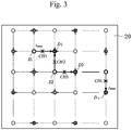
Fig. 3 is a schematic diagram illustrating the arrangement of the light irradiation probes S and the light detection probes D depicted inFig. 2 in a two-dimensional plane. -
Fig. 4 is a flowchart illustrating a method of implementing a first brain function measurement method according to an embodiment of the present invention through control by acontrol unit 3 depicted inFig. 1 . -
Fig. 5 depicts a second arrangement example of the light irradiation probes S1, S2 and the light detection probes D1, D2 on theholder 20 depicted inFig. 1 . -
Fig. 6 is a flowchart illustrating a method of implementing a second brain function measurement method according to an embodiment of the present invention through control by thecontrol unit 3 depicted inFig. 1 . -
Fig. 7 is a flowchart illustrating a method of implementing a third brain function measurement method according to an embodiment of the present invention through control by thecontrol unit 3 depicted inFig. 1 . -
Fig. 8 depicts a third arrangement example of the light irradiation probes S1, S2 and the light detection probes D1, D2 on theholder 20 depicted inFig. 1 . -
Fig. 9 is a schematic diagram depicting the arrangement of the light irradiation probes and the light detection probes depicted inFig. 8 in a two-dimensional plane. - In the following, embodiments of the present invention will be described in detail with reference to the drawings, wherein similar signs designate similar or corresponding portions.
-
Fig. 1 depicts a configuration of a brain function measurement system according to an embodiment of the present invention. As depicted inFig. 1 , the brain function measurement system is provided with: a brainfunction measurement device 1 including acontrol unit 3, a light source unit 5, a data measurement unit 7, and astorage unit 9; and aholder 20 includingoptical attenuators 11 to 14, and light irradiation probes S1, S2 and light detection probes D1, D2 that are attached to the subject. - The
control unit 3 is connected to the light source unit 5, the data measurement unit 7, thestorage unit 9, and theoptical attenuators 11 to 14. The light irradiation probes S1, S2 are connected to the light source unit 5 via theoptical attenuators optical attenuators 13, 14, respectively. The data measurement unit 7 is also connected to thestorage unit 9. - Meanwhile, the light irradiation probes S1, S2, for example, on the
holder 20 depicted inFig. 1 are arranged at the positions of light irradiation probes S indicated by white circles inFig. 2 . The light detection probes D1, D2 on theholder 20 depicted inFig. 1 are arranged at the positions of light detection probes D indicated by black circles inFig. 2 . InFig. 2 , the grey portion indicates hair; the same applies inFig. 5 andFig. 8 . - Referring to
Fig. 2 , the light irradiation probes S and the light detection probes D are arranged alternately, as illustrated by a schematic diagram ofFig. 3 , for example. -
Fig. 4 is a flowchart illustrating a method of implementing a first brain function measurement method according to an embodiment of the present invention through control by thecontrol unit 3 depicted inFig. 1 . In the following, with reference toFig. 3 , the first brain function measurement method ofFig. 4 will be described. It goes without saying that the first brain function measurement method ofFig. 4 depicted inFig. 1 is not limited to the case of implementation through control by thecontrol unit 3. - In step S1, the
control unit 3 adjusts the light amount detected by the second light detection probe D2 by controlling theoptical attenuator 12 connected to the second light irradiation probe S2 so that the light amount measured by the first light detection probe D1 with respect to a channel CH2 between the first light detection probe D1 and the second light irradiation probe S2 adjacent to each other becomes the value (observation value) of the light amount observed by the first light detection probe D1 with respect to a channel CH1 between the first light irradiation probe S1 adjacent to the first light detection probe D1 and the first light detection probe D1. - Then, in step S2, the
control unit 3 adjusts the light amount detected by the second light detection probe D2 by controlling theoptical attenuator 14 so that the light amount measured by the second light detection probe D2 with respect to a channel CH3 between the second light irradiation probe S2 and the second light detection probe D2 adjacent to the second light irradiation probe S2 becomes the observation value. - Then, in step S3, the
control unit 3 selects from a plurality of light irradiation probes a light irradiation probe having a maximum effective incident light amount, and selects from a plurality of light detection probes a light detection probe having a maximum effective detection efficiency. - Then, in step S4, the
control unit 3 performs, with respect to each of channels positioned on a shortest path connecting the light irradiation probe and the light detection probe that have been selected in step S3, step S1 and step S2 in the order of from the selected light irradiation probe to the selected light detection probe, and thereafter performs, with respect to each of the channels on the shortest path, step S2 and step S1 in the order of from the selected light detection probe to the selected light irradiation probe. - Then, in step S5, the
control unit 3 performs step S1 and step S2 between each of the channels positioned on the shortest path and a channel adjacent to said channel. In the following, a concrete example of the first brain function measurement method ofFig. 4 will be described. - With respect to a channel k, the observed light amount J at each wavelength λ is expressed by the following expression (1):
[Mathematical formula 1]
- In the above, ri,0,λ means a time-averaged value of optical transmittance between the light irradiation probe and the scalp; rj,0,λ means a time-averaged value of optical transmittance between the light detection probe and the scalp; and R means a time-averaged value of tissue transmittance.
- Any one of the
optical attenuators 11 to 14 depicted inFig. 1 is connected to one of n light irradiation probes and m light detector probes constituting multiple channels, wherein the optical attenuators connected to the light irradiation probes have transmittance ai (where i is 1 or more and n or less, ai is 0 or more and 1 or less), and the optical attenuators connected to the light detection probes have transmittance aj (where j is (n + 1) or more and (n + m) or less, aj is 0 or more and 1 or less). In this case, the magnitude h of noise included in an fNIRS signal in the channel k is expressed by the following expression (2):
[Mathematical formula 2]
- In the above, nj,λ(t) represents detector noise generated during measurement with a light detector probe j; differences between probes can be virtually disregarded when the detectors of the same standard are used. Thus, with reference to Expression (2), it is seen that levelling the magnitude h of noise included in the fNIRS signal between channels means levelling the observed light amount Jk,λ in each channel.
- Taking the logarithm of both sides of Expression (1) yields the following Expression (3):
[Mathematical formula 3]
- The coefficient C1 and coefficient C2 of Expression (3) satisfy the relationship of the following Expression (4):
[Mathematical formula 4]
- In the following, Ii,λlairi,0,λl in the first term of Expression (3) will be referred to as effective incident light amount, and rj,0,λlaj in the second term will be referred to as effective detection efficiency.
- Herein, the relationship between N measurement channels and the probes constituting the same is represented by a matrix G called a probe arrangement matrix. The matrix G is an N × (n + m) matrix of which the element g, when the light irradiation probe i and the light detector probe j constitute the channel k, is defined by the following Expression (5):
[Mathematical formula 5]
- Regardless of the scale or pattern of the channel or the arrangement of the probes, there is always only one matrix G that is determined correspondingly, and there is also always one pseudo-inverse matrix G+ of the matrix G that is determined correspondingly. With the probe arrangement matrix, it is possible to summarize the relationship of Expression (3) with respect to an arbitrary channel into a matrix operation according to the following Expression (6):
[Mathematical formula 6]
- In the above, sλ is a column vector having the logarithm logJk,λ (where k is 1 or more and N or less) of the observed light amount as an element, and is determined by actual measurement. On the other hand, ρλ is a column vector represented by the following expression (7) having, as the elements, the term log (Ii,λairi,0,λC1)(where i is 1 or more and n or less) relating to the effective incident light amount to be estimated, and the term log (rj,0,λlajC2)(where j is (n + 1) or more and (n + m) or less) relating to effective detection efficiency.
[Mathematical formula 7]
- Herein, by multiplying the Expression (7) with the pseudo-inverse matrix G+ from the left, a particular solution to ρλ is determined according to the following expression (8):
[Mathematical formula 8]
- Comparing Expression (7) with Expression (8) yields the relationships of the following expression (9) and Expression (10):
[Mathematical formula 9]
[Mathematical formula 10]
- In this way, the observed light amount Jk,λ for each channel is obtained, and when the matrix G designating the channel arrangement is known, it is possible to determine the effective incident light amount of each light irradiation probe and the effective detection efficiency of each light detection probe as ebi,λ/C1, ebj,λ/C2, respectively.
- In order to level the observed light amount, it is necessary to know not only the observed light amount but also the effective incident light amount and the effective detection efficiency for the following reason. The observed light amount is the product of the effective incident light amount and the effective detection efficiency. Even if there is a channel having a significantly different effective incident light amount, an apparently equal observed light amount may be indicated if the channel has a corresponding effective detection efficiency. Meanwhile, if there is even just one effective incident light amount exceeding a safe reference light amount, it cannot be said that the multiple channel measurement is being done safely. Accordingly, in order to confirm that the living body tissue is being irradiated with an amount of light less than or equal to the safe reference light amount, it is necessary to monitor the effective incident light amount.
- Now, in the multiple-channel probe arrangement depicted in
Fig. 3 , it is possible to select, based on Expression (8), a light irradiation probe imax having a maximum effective incident light amount and a light detection probe jmax having a maximum effective detection efficiency. Herein, it is assumed that the shortest path connecting the light irradiation probe imax and the light detection probe jmax is configured of v light irradiation probes and v light detection probes, and levelling of the observed light amounts in (2v-1) channels on the path will be described. - The light irradiation probes in the path are designated with signs S1, S2,..., Sv; the light detection probes are designated with signs D1, D2,..., Dv; and the respective channels are designated with signs CH1, CH2,..., CHκ (where κ = 2v-1). Thus, in
Fig. 3 , S1 indicates the light irradiation probe imax, and Dv indicates the light detection probe jmax. - In the following, for simplicity of illustration, only the channels CH1 to CH3 will be considered. In this case, the content of Expression (6) can be rewritten as Expression (11):
[Mathematical formula 11]
- In Expression (11), with respect to SCH1 to SCH3, measurement values can be calculated successively. Herein, it is contemplated to equalize SCH2 and SCH3 with the observation value of SCH1/SCH1. First, while monitoring the observed light amounts of channel CH1 and channel CH2, the
optical attenuator 12 connected to the light irradiation probe S2 is controlled so that SCH2 becomes the observation value/SCH1. In this way, it becomes possible to achieve a state expressed by the following Expression (12):
[Mathematical formula 12]
- Then, while monitoring the observed light amounts in channel CH2 and channel CH3, the
optical attenuator 14 connected to the light detection probe D2 is controlled so that SCH3 becomes the observation value/SCH1. Through such control, it becomes possible to achieve a state expressed by the following Expression (13):
[Mathematical formula 13]
- Herein, a necessary and sufficient condition for Expression (13) to be valid is expressed by the following Expression (14):
[Mathematical formula 14]
- Thus, it is seen that, through the series of operations described above, the observed light amounts are levelled to e(ρS1 + ρD1) in channels CH1 to CH3, and that the effective incident light amounts of all of the light irradiation probes and the effective detection efficiencies of all of the detection probes are respectively levelled to eρS1, eρD1. The present operation is a core means for achieving noise levelling without controlling the transmittances ai, aj to designated values, and the operation will be hereafter referred to as an adjacent channel levelling operation. Referring to
Fig. 3 , by expanding the adjacent channel levelling operation from channel CH4 (not illustrated) onto channel CHv, it becomes possible to perform levelling in all of the channels CH1 to CHv. - Thus, with the levelling operation between adjacent channels, it is possible to perform levelling for adjacent channels or probes in accordance with the observed light amount of a reference-point channel, or the effective incident light amount or the effective detection efficiency of the light irradiation probe or the light detection probe that constitutes that channel. The adjacent channel levelling operation can be expanded onto a channel linked via a light irradiation probe or a light detection probe. The multiple channels configured by such linking will be referred to as a linked channel group.
- In the above operation, the effective detection efficiencies of a series of light detection probes are levelled to eρD1. However, because the effective detection efficiency of the light detection probe Dv constituting the channel CHv is the highest among all of the light detection probes, eρDν is obviously greater than eρD1. Accordingly, in order to maximize the observed light amount and level the noise to the maximum achievable S/N ratio, it is necessary to level the effective detection efficiency of each light detection probe to eρDν. In the following, this operation will be described.
- In order to achieve the purpose, the adjacent channel levelling operation is terminated at the point in time that the channel CH(κ-1) has been reached. The state at this point in time may be described, with respect to only the interval between channel CH(κ-2) to channel CHκ for sake of simplicity, by the following Expression (15):
[Mathematical formula 15]
- Herein, while monitoring the observed light amounts of channel CH(κ-1) and channel CHκ, the optical attenuator connected to the light detection probe D(ν-1) is controlled so that SCH(κ-1) becomes the observation value/SCHκ. In this way, a state expressed by the following Expression (16) is achieved.
[Mathematical formula 16]
- From Expression (16), it is seen that the following Expression (17) is also valid.
[Mathematical formula 17]
- Accordingly, it is seen that at the same time that the observed light amount is levelled to e(ρS1 + ρDν) from channel CH(κ-2) to channel CHκ, the effective incident light amounts of all of the light irradiation probes and the effective detection efficiencies of all of the light detection probes are respectively levelled to eρS1, eρDν. By tracing the present operation from channel CH(ν-3) to channel CH1, all of the channels from channel CHκ to channel CH1 can be levelled to the observed light amount e(ρS1 + ρDν).
- With the above-described procedure, it is possible to level the observed light amounts between the light irradiation probe imax having the maximum effective incident light amount and the light detection probe jmax having the maximum effective detection efficiency in an arbitrary linked channel group, and to further level the observed light amounts by the adjacent channel levelling operation with respect to all of the channels in the group. In view of the above, the procedure for levelling within a linked channel group is summarized as follows.
- First, after the probes have been attached to the head of the subject, the transmittance of all of the optical attenuators on the irradiating side and the detection side are set to approximately 50%, and all of the light source outputs are set to a maximum light amount Isafe of light irradiation that is safe with respect to the living body (subject).
- Second, the wavelength λ is selected, ebi,λ and ebj,λ of each probe are estimated according to Expression (9) and Expression (10), and the light irradiation probe imax such that ebi,λ has a maximum value and the light detection probe jmax such that ebj,λ has a maximum value are selected.
- Third, the adjacent channel levelling operation is performed for the channels on the shortest path connecting the light irradiation probe imax and the light detection probe jmax, and the observed light amounts are equalized to e(bimax,λ + bjmax,λ)
- Fourth, the adjacent channel levelling operation is performed similarly with respect to a channel adjacent to the channels levelled in the third procedure.
- Fifth, the second to fourth procedures are performed with respect to all of the wavelengths being used. Sixth, fNIRS measurement is performed in a state in which the setting determined up to the fifth procedure is maintained. And seventh, the process returns back to the first procedure at the end of the measurement, or all of the light source outputs are shut down.
- In order to level the noise variance in accordance with as low a level as possible, it is desirable to provide, for at least one channel of the link group being measured, a light irradiation probe Sa and a light detection probe Da for being arranged in a hairless head portion, such as the forehead, and a light irradiation probe S and a light detection probe D, as depicted in
Fig. 5 . The reason is as follows. - Because the effective incident light amount and the effective detection efficiency in a channel in the hairless portion are significantly greater than in the hairy portion, and are also temporally constant, the noise variance of the channel is significantly small. Accordingly, by performing the levelling based on probe attachment including the hairless portion and with the channel being used as a reference point, it becomes possible to level all channels to the signal-to-noise ratio of the best level within the range of safe light irradiation intensity.
- Next, a noise variance normalizing technique will be described which is useful when it is desired to statistically compare data obtained by performing fNIRS measurement at different dates/times or data obtained with respect to different subjects.
- The present technique, which comes down to levelling the noise variance of two independent linked channel groups (non-linked two groups), cannot be implemented by the levelling procedure in the linked channel group. Thus, in the following, methods of noise levelling between only temporally non-linked two groups and noise levelling between temporally and spatially non-linked two groups will be described.
- The only temporally non-linked two groups refer to the case in which, for example, fNIRS measurement is performed at different dates/times with respect to the identical subject or identical site. In the following, an example in which the noise levelling method for two groups in this case is implemented by the
control unit 3 depicted inFig. 1 will be described with reference toFig. 6 . It goes without saying that the brain function measurement method ofFig. 6 is not limited to the case of implementation through control by thecontrol unit 3 depicted inFig. 1 . - According to the brain function measurement method of
Fig. 6 , as a premise, theholder 20 is attached to the head of the subject, as depicted inFig. 5 , whereby the light irradiation probe Sa and the light detection probe Da for arranging a channel in a morphologically easily localizable site of a hairless head portion, such as the forehead, and the light irradiation probe S and the light detection probe D are disposed. - Then, initially in step S6, the
control unit 3, after performing step S1 and step S2 ofFig. 4 , saves the observation value obtained in step S1 in thestorage unit 9 as a reference value (reference observed light amount). - Then, in step S7, the
control unit 3, during a measurement as a reference at the hairless head portion, such as the forehead, turns off the function of the optical attenuator connected to at least one light detection probe, thereby making the transmittance of light entering thelight detection probe 100%. Thecontrol unit 3 then saves the maximum light amount value (maximum observed light amount) observed with respect to a channel measured by the at least one light detection probe in thestorage unit 9. - Then, in step S8, the
control unit 3, in a state in which the function of the optical attenuator connected to at least one light detection probe in an independent channel group to be leveled at the hairless head portion, such as the forehead, is turned off, makes the transmittance of light entering thelight detection probe 100%, and adjusts the optical attenuator connected to the light irradiation probe for measurement with respect to the channel to be levelled, so that the light amount observed with respect to the channel corresponds to the maximum light amount value, thereby adjusting the light amount irradiated from the present light irradiation probe. - Then, in step S9, the
control unit 3, after performing step S8, adjusts the optical attenuator connected to the light detection probe for measurement with respect to the channel to be leveled so that the value of the light amount observed with respect to the channel corresponds to the reference value, thereby adjusting the light amount detected by the light detection probe. At this stage, the effective incident light amount and the effective detection efficiency of the channel respectively correspond to the values of the effective incident light amount and the effective detection efficiency in the channel group as the levelling reference. - Next, in step S10, the
control unit 3, assuming that the channel to be leveled corresponds to the channel between the first light detection probe and the first light irradiation probe depicted inFig. 4 , performs step S1 to step S5 ofFig. 4 . As a result of this step, the noise variance of the channel group comes to correspond to the noise variance of the channel group as the levelling reference. - In the following, it will be described how, with the brain function measurement method of
Fig. 6 , levelling of non-linked two groups is implemented. When the reference observed light amount and the maximum observed light amount obtained in step S6 and step S7 ofFig. 6 are J(1), J(2), respectively, log J(1) is S(1), and log J(2) is S(2), the following Expression (18) and Expression (19) are valid.
[Mathematical formula 18]
[Mathematical formula 19]
- Herein, ρj0 of Expression (19) is the logarithm of the effective detection efficiency at the time of measuring the maximum observed light amount, when the function of the optical attenuator connected to the light detection probe is turned off and the optical transmittance is made 100%. When the channel of another link group which is independent of the reference link group and attached to the hairless portion is CH, and the light irradiation probe and the light detection probe constituting the channel are respectively s, d, the following Expression (20) is valid.
[Mathematical formula 20]
- Herein, if, according to step S7, the function of the optical attenuator connected to the light detection probe d for measuring the channel CH is turned off, pd of Expression (20) corresponds to ρj0 in view of the constancy of observation at the hairless head portion as mentioned in paragraph [0073]. Accordingly, the following Expression (21) is valid.
[Mathematical formula 21]
- Further, it is seen that by adjusting the optical attenuator connected to the light irradiation probe such that SCH becomes S(2), as described in step S8, ps can be made ρimax from a comparison of Expression (19) and Expression (21). In this case, the following Expression (22) is valid.
[Mathematical formula 22]
- Further, it is seen that by adjusting the optical attenuator connected to the light detection probe such that SCH becomes S(1), as described in step S9, ρj0 can be made ρjmax from a comparison of Expression (18) and Expression (22). In this case, the following Expression (23) is valid.
[Mathematical formula 23]
- Then, by performing levelling by the method of
Fig. 4 using the channel as a reference point, it becomes possible to level the channels in a single link group to the noise variance of the reference link group. - When performing measurement of the top of the head in which motor-related areas and the like are positioned, it is often inefficient to arrange the reference-point channel at the forehead as described above, for example, because of the distance from the position to be measured. Meanwhile, in the absence of a spatially common reference point, the two groups become non-linked not only temporally but also spatially.
- Accordingly, in the following, an example in which a method of performing noise levelling for temporally and spatially non-linked two groups is implemented through control by the
control unit 3 depicted inFig. 1 will be described with reference toFig. 7 . - It goes without saying that the brain function measurement method of
Fig. 7 is not limited to the case of implementation through control by thecontrol unit 3 depicted inFig. 1 . - According to the brain function measurement method of
Fig. 7 , as a premise, designated value-controllable optical attenuators are only connected to three probes constituting specific two reference channels adjacent to each other in a link group, as depicted inFig. 8 , i.e., only to reference irradiation probes SS1, SS2 and a reference detection probe SD; and
thecontrol unit 3 adjusts each of the optical attenuators so that the transmittances of the optical attenuators become designated values. -
Fig. 9 is a schematic diagram illustrating the arrangement of the light irradiation probes and the light detection probes ofFig. 8 in a two-dimensional plane. The light irradiation probe S1 ofFig. 9 corresponds to the reference irradiation probe SS1, and the light irradiation probe S2 ofFig. 9 corresponds to the reference irradiation probe SS2. The light detection probe D1 ofFig. 9 corresponds to the reference detection probe SD. The channels CH1, CH2 ofFig. 9 correspond to the two reference channels. - First, in step S16, the
control unit 3, with respect to measurement of linked multiple channels including the reference channels SCH1, SCH2, performs noise levelling by applying the method ofFig. 4 , and saves the obtained values of effective detection efficiency and effective incident light amount in thestorage unit 9. - Then, when linked multiple-channel measurement has been performed at another date/time or in a different position, the
control unit 3 in step S17 controls the optical attenuator connected to the reference detection probe SD, and thereby makes the detection efficiency at the reference detection probe SD the effective detection efficiency saved in step S16. Thecontrol unit 3 also controls the optical attenuators connected to the reference irradiation probes SS1, SS2, and thereby makes the irradiation light amount at the reference irradiation probes SS1, SS2 the effective incident light amount saved in step S16. - Then, in step S18, the
control unit 3, after step S17, again performs step S1 to step S5 ofFig. 4 , i.e., the adjacent channel levelling operation, from the reference channels SCH1, SCH2 as reference points, and performs noise levelling with respect to all of the channels in the linked channel group. - In the following, with reference to
Fig. 9 , the control method in step S17 will be described concretely. With respect to the channels CH1, CH2 depicted inFig. 9 , i.e., the light irradiation probes S1, S2 and the light detection probe D1, the following Expression (24) is valid.
[Mathematical formula 24]
- By subjecting Expression (24) to general inverse matrix computation of the probe arrangement matrix, the following Expression (25) is obtained.
[Mathematical formula 25]
- In each channel of the reference link group for which levelling has been completed, Expression (23) is valid. Further, when designated value-controllable elements as described above are used, it is possible to obtain the transmittance ax of the optical attenuator connected to the probe x providing px, concretely according to Expression (7). This indicates that in order to make ρS1 ρimax and ρD1 ρjmax, the transmittance aS1 may be multiplied by e(ρimax-ρS1) and the transmittance aD1 by e(ρjmax-ρD1).
- In Expression (24) and
Fig. 9 , as the reference detection probe and the reference irradiation probes, one light detection probe D1 and two light irradiation probes S1, S2 sandwiching the same are used, respectively. Instead, one light irradiation probe and two light detection probes sandwiching the same may be used, in which case it is possible to level the link group by the same method. - With the brain function measurement device according to the embodiment of the present invention, and with a brain function measurement system and a brain function measurement method incorporating the device, it is possible to eliminate or minimize the need for a calibration operation for the device. That is, the noise of all of the channels in a linked channel group can be leveled without adjusting the transmittance of an optical attenuator to a designated value.
- More specifically, according to the methods of
Fig. 4 andFig. 6 , the need for calibration of the optical attenuator is eliminated. Meanwhile, according to the method ofFig. 7 , while it is necessary to use designated value-controllable optical attenuators in three probes, it is sufficient in this case, too, if only three designated value-controllable optical attenuators are connected to the three probes, no matter how large the number of channels becomes. Accordingly, it is possible to greatly simplify the adjustment or maintenance of the brain function measurement device or a system including the device, and to achieve size reduction. - In another aspect, with the brain function measurement device according to the embodiment of the present invention and the brain function measurement system or the brain function measurement method incorporating the device, it is possible to level noise variance between a plurality of independent link groups. The method includes a method by which, as indicated in
Fig. 6 , a reference point at which the noise variance can be assumed to be temporally invariable is commonly set between groups, and a method by which, as indicated inFig. 7 , designated value-controllable optical attenuators are used only in probes constituting two channels adjacent to each other in one group. - Both of the methods make it possible to perform statistical comparison of chronological changes in data of a single subject. In addition, the latter method makes it possible to perform statistical comparison with respect to measurements pertaining to a plurality of subjects or at a plurality of sites of the head.
- Further, in yet another aspect, with the brain function measurement device according to the embodiment of the present invention and the brain function measurement system or the brain function measurement method incorporating the device, it is possible, by using a channel placed in a hairless portion as a levelling reference point, to level noise variance in measurements at any sites that can be linked or at any date/time, in accordance with the level of the hairless portion. Accordingly, it is possible to obtain a maximum achievable signal-to-noise ratio steadily, while observing a safe range of light irradiation intensity.
-
- 1
- Brain function measurement device
- 3
- Control unit
- 5
- Light source unit
- 7
- Data measurement unit
- 9
- Storage unit
- 11 to 14
- Optical attenuator
- S, S1, S2
- Light irradiation probe
- D, D1 to D3
- Light detection probe
- SS1, SS2
- Reference irradiation probe
- SD
- Reference detection probe
Claims (12)
- A brain function measurement device comprising:a first irradiation means that irradiates the brain of a subject with light;a first detection means which is disposed adjacent to the first irradiation means and detects light reflected by the brain among the light irradiated from the first irradiation means;a second irradiation means which is disposed adjacent to the first detection means and irradiates the brain of the subject with light;a second detection means which is disposed adjacent to the second irradiation means and detects light reflected by the brain among the light irradiated from the second irradiation means; anda control means that performs first adjustment with respect to a light amount irradiated by the second irradiation means so that a light amount measured with respect to a measurement point between the first detection means and the second irradiation means becomes an observation value observed with respect to a measurement point between the first irradiation means and the first detection means, and that performs second adjustment with respect to a light amount detected by the second detection means so that a light amount measured with respect to a measurement point between the second irradiation means and the second detection means becomes the observation value.
- The brain function measurement device according to claim 1, comprising a plurality of the irradiation means and the detection means,
wherein the control means selects, from among the plurality of the irradiation means, the irradiation means having a maximum effective incident light amount, selects, from among a plurality of the detection means, the detection means having a maximum effective detection efficiency, performs, with respect to each of the measurement points positioned on a shortest path connecting the irradiation means and the detection means that have been selected, the first and second adjustments in the order from the selected irradiation means to the selected detection means, and then performs, with respect to each of the measurement points positioned on the shortest path, the second and first adjustments in the order from the selected detection means to the selected irradiation means. - The brain function measurement device according to claim 2, wherein the control means performs the adjustments for each and every wavelength used.
- The brain function measurement device according to claim 2, wherein at least one of the measurement point irradiated by the irradiation means having the maximum effective incident light amount and the measurement point detected by the detection means having the maximum effective detection efficiency is disposed in a hairless portion of the subject.
- The brain function measurement device according to claim 4, further comprising a storage means,
wherein the control means further:adjusts the light amount irradiated by the second irradiation means so that the light amount measured with respect to the measurement point between the first detection means and the second irradiation means becomes the observation value observed with respect to the measurement point between the first irradiation means and the first detection means, adjusts the light amount detected by the second detection means so that the light amount measured with respect to the measurement point between the second irradiation means and the second detection means becomes the observation value, then saves the observation value in the storage means as a reference value, and saves a maximum light amount value observed with respect to the measurement point measured by the at least one of the detection means in the storage means when the transmittance of light entering at least one of the detection means is made 100%; andmakes the transmittance of light entering at least one of the detection means for measurement with respect to the measurement point to be leveled 100%, adjusts the light amount irradiated from the irradiation means for measurement with respect to the measurement point to be leveled so that the light amount observed with respect to the measurement point to be leveled becomes the maximum light amount value, then adjusts the light amount detected by the detection means for measurement with respect to the measurement point to be leveled so that the value of the light amount observed with respect to the measurement point to be leveled becomes the reference value, and performs adjustment of the irradiation means on the assumption that the measurement point to be leveled is a measurement point between the first detection means and the first irradiation means. - The brain function measurement device according to claim 2, further comprising a storage means,
wherein the control unit further:saves, in the storage means, the value of effective detection efficiency of the first detection means and the value of effective incident light amount of the first irradiation means at the point when the light amount irradiated by the second irradiation means has been adjusted so that the light amount measured with respect to the measurement point between the first detection means and the second irradiation means becomes the observation value observed with respect to the measurement point between the first irradiation means and the first detection means, and when the light amount detected by the second detection means has been adjusted so that the light amount measured with respect to the measurement point between the second irradiation means and the second detection means becomes the observation value; andmakes the detection efficiency at the first detection means the effective detection efficiency that has been saved, makes the irradiation light amount at the first irradiation means the effective incident light amount that has been saved, and again performs the adjustment with respect to the irradiation means. - A brain function measurement method for measuring brain function by irradiating the brain of a subject with light and detecting light reflected by the brain,
the method comprising:a first step of adjusting a light amount irradiated by a second irradiation means so that a light amount measured with respect to a measurement point between a first detection means and the second irradiation means adjacent to each other becomes an observation value observed with respect to a measurement point between a first irradiation means adjacent to the first detection means and the first detection means; anda second step of adjusting the light amount detected by the second detection means so that a light amount measured with respect to a measurement point between the second irradiation means and a second detection means adjacent to the second irradiation means becomes the observation value. - The brain function measurement method according to claim 7, wherein the brain function measurement method is a method for measuring the brain function at a plurality of the measurement points, and further comprises:a third step of selecting an irradiation means from among the plurality of the irradiation means that has a maximum effective incident light amount, and selecting a detection means from among a plurality of the detection means that has a maximum effective detection efficiency;a fourth step of, with respect to each of the measurement points positioned on a shortest path connecting the irradiation means and the detection means that have been selected in the third step, performing the first and second steps in the order from the selected irradiation means to the selected detection means, and then, with respect to each of the measurement points positioned on the shortest path, performing the second and first steps in the order from the selected detection means to the selected irradiation means; anda fifth step of performing the first step and the second step between each of the measurement points positioned on the shortest path and the measurement point adjacent to said each of the measurement points.
- The brain function measurement method according to claim 8, wherein the third to the fifth steps are performed for each and every wavelength used.
- The brain function measurement method according to claim 8, wherein at least one of the measurement point irradiated by the irradiation means having the maximum effective incident light amount and the measurement point detected by the detection means having the maximum effective detection efficiency is disposed in a hairless portion of the subject.
- The brain function measurement method according to claim 10, further comprising:a sixth step of saving the observation value as a reference value after the second step has been performed;a seventh step of saving a maximum light amount value observed with respect to the measurement point measured by the at least one of the detection means when the transmittance of light entering at least one of the detection means is made 100%;an eighth step of making the transmittance of light entering at least one of the detection means for measurement with respect to the measurement point to be leveled 100%, and adjusting the light amount irradiated from the irradiation means for measurement with respect to the measurement point to be leveled so that the light amount observed with respect to the measurement point to be leveled becomes the maximum light amount value;a ninth step of, after the eighth step has been performed, adjusting the light amount detected by the detection means for measurement with respect to the measurement point to be leveled so that the value of the light amount observed with respect to the measurement point to be leveled becomes the reference value; anda tenth step of performing the first step to the fifth step, assuming that the measurement point to be leveled is the measurement point between the first detection means and the first irradiation means.
- The brain function measurement method according to claim 8, comprising:a sixth step of saving the value of the effective detection efficiency and the value of the effective incident light amount at the point in time when the fifth step has been completed; anda seventh step of making a detection efficiency at the detection means for measuring two of the measurement points adjacent to each other as a reference the effective detection efficiency saved in the sixth step, and making an irradiation light amount at the irradiation means for measuring the two measurement points the effective incident light amount that has been saved in the sixth step,wherein, after the seventh step, the first to fifth steps are performed again, using the measurement points providing the reference as reference points.
Applications Claiming Priority (2)
| Application Number | Priority Date | Filing Date | Title |
|---|---|---|---|
| JP2017080533 | 2017-04-14 | ||
| PCT/JP2018/012853 WO2018190130A1 (en) | 2017-04-14 | 2018-03-28 | Brain function measurement device and brain function measurement method |
Publications (3)
| Publication Number | Publication Date |
|---|---|
| EP3610796A1 true EP3610796A1 (en) | 2020-02-19 |
| EP3610796A4 EP3610796A4 (en) | 2021-01-13 |
| EP3610796B1 EP3610796B1 (en) | 2024-09-25 |
Family
ID=63792645
Family Applications (1)
| Application Number | Title | Priority Date | Filing Date |
|---|---|---|---|
| EP18783722.4A Active EP3610796B1 (en) | 2017-04-14 | 2018-03-28 | Brain function measurement device and method |
Country Status (5)
| Country | Link |
|---|---|
| US (1) | US11478149B2 (en) |
| EP (1) | EP3610796B1 (en) |
| JP (1) | JP6784976B2 (en) |
| CN (1) | CN110520057B (en) |
| WO (1) | WO2018190130A1 (en) |
Families Citing this family (4)
| Publication number | Priority date | Publication date | Assignee | Title |
|---|---|---|---|---|
| US20200077906A1 (en) * | 2018-09-07 | 2020-03-12 | Augusta University Research Institute, Inc. | Method and System for Monitoring Brain Function and Intracranial Pressure |
| WO2020174842A1 (en) * | 2019-02-27 | 2020-09-03 | 国立研究開発法人産業技術総合研究所 | Brain function measurement device, brain function measurement method, and probe |
| CN113951833A (en) * | 2021-11-29 | 2022-01-21 | 武汉资联虹康科技股份有限公司 | Channel pluggable portable near-infrared brain function imaging system and method |
| CN119908662A (en) * | 2024-12-31 | 2025-05-02 | 北京津发科技股份有限公司 | fNIRS functional optical brain imaging signal quality assessment method, device, storage medium and electronic device |
Family Cites Families (9)
| Publication number | Priority date | Publication date | Assignee | Title |
|---|---|---|---|---|
| US5803909A (en) | 1994-10-06 | 1998-09-08 | Hitachi, Ltd. | Optical system for measuring metabolism in a body and imaging method |
| JP5303184B2 (en) | 2008-05-08 | 2013-10-02 | 株式会社日立製作所 | Biological light measurement device |
| US8644901B2 (en) * | 2010-02-23 | 2014-02-04 | Covidien Lp | System and method of resolving outliers in NIRS cerebral oximetry |
| WO2012005303A1 (en) * | 2010-07-06 | 2012-01-12 | 株式会社日立メディコ | Biological photometric device and biological photometry method using same |
| WO2014034285A1 (en) * | 2012-08-31 | 2014-03-06 | 株式会社日立メディコ | Biophotonic measurement apparatus and biophotonic measurement method using same |
| JP6004430B2 (en) * | 2012-10-19 | 2016-10-05 | 国立研究開発法人産業技術総合研究所 | Biological light measurement device |
| JP6594620B2 (en) | 2013-12-20 | 2019-10-23 | パナソニック インテレクチュアル プロパティ コーポレーション オブ アメリカ | Optical brain function measuring device |
| CN104363983B (en) * | 2014-08-06 | 2017-03-01 | 中国科学院自动化研究所 | Brain activity detection method and system |
| JP6381168B2 (en) * | 2015-02-16 | 2018-08-29 | 国立研究開発法人産業技術総合研究所 | Near-infrared brain function measuring device and measuring method |
-
2018
- 2018-03-28 US US16/603,756 patent/US11478149B2/en active Active
- 2018-03-28 JP JP2019512420A patent/JP6784976B2/en active Active
- 2018-03-28 WO PCT/JP2018/012853 patent/WO2018190130A1/en not_active Ceased
- 2018-03-28 EP EP18783722.4A patent/EP3610796B1/en active Active
- 2018-03-28 CN CN201880024648.9A patent/CN110520057B/en active Active
Also Published As
| Publication number | Publication date |
|---|---|
| CN110520057A (en) | 2019-11-29 |
| WO2018190130A1 (en) | 2018-10-18 |
| JPWO2018190130A1 (en) | 2020-05-14 |
| US20200029819A1 (en) | 2020-01-30 |
| JP6784976B2 (en) | 2020-11-18 |
| EP3610796A4 (en) | 2021-01-13 |
| EP3610796B1 (en) | 2024-09-25 |
| CN110520057B (en) | 2022-05-13 |
| US11478149B2 (en) | 2022-10-25 |
Similar Documents
| Publication | Publication Date | Title |
|---|---|---|
| EP3610796B1 (en) | Brain function measurement device and method | |
| US12548643B2 (en) | Brain network activity estimation system, method of estimating activities of brain network, brain network activity estimation program, and trained brain activity estimation model | |
| WO2003028548A3 (en) | Method of measurement of wave aberrations of an eye | |
| EP0755218B1 (en) | Method and apparatus for determining spectral sensitivity parameters of colour-sensitive receptors in the eye | |
| CN102353448B (en) | An Absolute Calibration Method for Radiance of Hadamard Transform Imaging Spectrometer | |
| CN111175239A (en) | High-spectrum nondestructive testing and identifying system for imaging of colored drawing cultural relics under deep learning | |
| Moiseev | Reduction of CCD observations made with a scanning Fabry–Perot interferometer. III. Wavelength scale refinement | |
| CN120381348A (en) | Non-invasive detection method of alveolar bone based on spatially offset Raman spectroscopy | |
| EP3260049B1 (en) | Functional near-infrared spectroscope and spectroscopy | |
| KR102655740B1 (en) | Apparatus and method for correcting spectral image and, apparatus and method for analyzing substances of object | |
| CN109541100A (en) | Signal drift processing method, device and the multichannel detector of multi-channel wavelength | |
| EP3791793B1 (en) | Brain function measurement device and brain function measurement method | |
| White | Limb-Darkening Observations of HAlpha, HBeta, and HGamma | |
| US11788976B2 (en) | X-ray measurement apparatus and X-ray measurement method | |
| US4993831A (en) | Closed loop Foucault knife-edge test | |
| RU2108056C1 (en) | Method for controlling quality of color vision function | |
| Freudenthaler et al. | European Aerosol Research LIDAR Network–advanced sustainable observation system (EARLINET-ASOS), Plans for quality assurance | |
| Bakker et al. | MIDI scientific and technical observing modes | |
| CN119818017A (en) | Detection system based on artificial intelligence and having abnormal color vision ability | |
| Schmitz et al. | Data integrity assessment and instrument calibration for the DYNOT imaging system | |
| CN119595123A (en) | Automatic online calibration method and system for infrared thermometer | |
| Evans et al. | Instrument for scanning the angular variation of irradiance in ultraviolet phototherapy cabinets | |
| HUP9802809A2 (en) | Method and device for determining spectral sensibility parameters of the colour sensing receptors of the eye | |
| Rees et al. | Real Time Stokes Inversion Using Multiple Support Vector Regression | |
| US20070275343A1 (en) | Device and method for evaluation of the shade of an object by spectrometry |
Legal Events
| Date | Code | Title | Description |
|---|---|---|---|
| STAA | Information on the status of an ep patent application or granted ep patent |
Free format text: STATUS: THE INTERNATIONAL PUBLICATION HAS BEEN MADE |
|
| PUAI | Public reference made under article 153(3) epc to a published international application that has entered the european phase |
Free format text: ORIGINAL CODE: 0009012 |
|
| STAA | Information on the status of an ep patent application or granted ep patent |
Free format text: STATUS: REQUEST FOR EXAMINATION WAS MADE |
|
| 17P | Request for examination filed |
Effective date: 20191004 |
|
| AK | Designated contracting states |
Kind code of ref document: A1 Designated state(s): AL AT BE BG CH CY CZ DE DK EE ES FI FR GB GR HR HU IE IS IT LI LT LU LV MC MK MT NL NO PL PT RO RS SE SI SK SM TR |
|
| AX | Request for extension of the european patent |
Extension state: BA ME |
|
| DAV | Request for validation of the european patent (deleted) | ||
| DAX | Request for extension of the european patent (deleted) | ||
| REG | Reference to a national code |
Ipc: A61B0005145000 Ref country code: DE Ref legal event code: R079 Ref document number: 602018074736 Country of ref document: DE Free format text: PREVIOUS MAIN CLASS: A61B0010000000 Ipc: A61B0005145000 |
|
| A4 | Supplementary search report drawn up and despatched |
Effective date: 20201215 |
|
| RIC1 | Information provided on ipc code assigned before grant |
Ipc: A61B 5/1455 20060101ALI20201209BHEP Ipc: A61B 5/00 20060101ALI20201209BHEP Ipc: A61B 5/145 20060101AFI20201209BHEP |
|
| GRAP | Despatch of communication of intention to grant a patent |
Free format text: ORIGINAL CODE: EPIDOSNIGR1 |
|
| STAA | Information on the status of an ep patent application or granted ep patent |
Free format text: STATUS: GRANT OF PATENT IS INTENDED |
|
| INTG | Intention to grant announced |
Effective date: 20240423 |
|
| GRAS | Grant fee paid |
Free format text: ORIGINAL CODE: EPIDOSNIGR3 |
|
| GRAA | (expected) grant |
Free format text: ORIGINAL CODE: 0009210 |
|
| STAA | Information on the status of an ep patent application or granted ep patent |
Free format text: STATUS: THE PATENT HAS BEEN GRANTED |
|
| AK | Designated contracting states |
Kind code of ref document: B1 Designated state(s): AL AT BE BG CH CY CZ DE DK EE ES FI FR GB GR HR HU IE IS IT LI LT LU LV MC MK MT NL NO PL PT RO RS SE SI SK SM TR |
|
| REG | Reference to a national code |
Ref country code: GB Ref legal event code: FG4D |
|
| REG | Reference to a national code |
Ref country code: CH Ref legal event code: EP |
|
| REG | Reference to a national code |
Ref country code: DE Ref legal event code: R096 Ref document number: 602018074736 Country of ref document: DE |
|
| REG | Reference to a national code |
Ref country code: IE Ref legal event code: FG4D |
|
| REG | Reference to a national code |
Ref country code: LT Ref legal event code: MG9D |
|
| PG25 | Lapsed in a contracting state [announced via postgrant information from national office to epo] |
Ref country code: NO Free format text: LAPSE BECAUSE OF FAILURE TO SUBMIT A TRANSLATION OF THE DESCRIPTION OR TO PAY THE FEE WITHIN THE PRESCRIBED TIME-LIMIT Effective date: 20241225 |
|
| PG25 | Lapsed in a contracting state [announced via postgrant information from national office to epo] |
Ref country code: GR Free format text: LAPSE BECAUSE OF FAILURE TO SUBMIT A TRANSLATION OF THE DESCRIPTION OR TO PAY THE FEE WITHIN THE PRESCRIBED TIME-LIMIT Effective date: 20241226 Ref country code: FI Free format text: LAPSE BECAUSE OF FAILURE TO SUBMIT A TRANSLATION OF THE DESCRIPTION OR TO PAY THE FEE WITHIN THE PRESCRIBED TIME-LIMIT Effective date: 20240925 |
|
| PG25 | Lapsed in a contracting state [announced via postgrant information from national office to epo] |
Ref country code: BG Free format text: LAPSE BECAUSE OF FAILURE TO SUBMIT A TRANSLATION OF THE DESCRIPTION OR TO PAY THE FEE WITHIN THE PRESCRIBED TIME-LIMIT Effective date: 20240925 |
|
| PG25 | Lapsed in a contracting state [announced via postgrant information from national office to epo] |
Ref country code: LV Free format text: LAPSE BECAUSE OF FAILURE TO SUBMIT A TRANSLATION OF THE DESCRIPTION OR TO PAY THE FEE WITHIN THE PRESCRIBED TIME-LIMIT Effective date: 20240925 |
|
| PG25 | Lapsed in a contracting state [announced via postgrant information from national office to epo] |
Ref country code: RS Free format text: LAPSE BECAUSE OF FAILURE TO SUBMIT A TRANSLATION OF THE DESCRIPTION OR TO PAY THE FEE WITHIN THE PRESCRIBED TIME-LIMIT Effective date: 20241225 |
|
| REG | Reference to a national code |
Ref country code: NL Ref legal event code: MP Effective date: 20240925 |
|
| PG25 | Lapsed in a contracting state [announced via postgrant information from national office to epo] |
Ref country code: RS Free format text: LAPSE BECAUSE OF FAILURE TO SUBMIT A TRANSLATION OF THE DESCRIPTION OR TO PAY THE FEE WITHIN THE PRESCRIBED TIME-LIMIT Effective date: 20241225 Ref country code: NO Free format text: LAPSE BECAUSE OF FAILURE TO SUBMIT A TRANSLATION OF THE DESCRIPTION OR TO PAY THE FEE WITHIN THE PRESCRIBED TIME-LIMIT Effective date: 20241225 Ref country code: LV Free format text: LAPSE BECAUSE OF FAILURE TO SUBMIT A TRANSLATION OF THE DESCRIPTION OR TO PAY THE FEE WITHIN THE PRESCRIBED TIME-LIMIT Effective date: 20240925 Ref country code: GR Free format text: LAPSE BECAUSE OF FAILURE TO SUBMIT A TRANSLATION OF THE DESCRIPTION OR TO PAY THE FEE WITHIN THE PRESCRIBED TIME-LIMIT Effective date: 20241226 Ref country code: FI Free format text: LAPSE BECAUSE OF FAILURE TO SUBMIT A TRANSLATION OF THE DESCRIPTION OR TO PAY THE FEE WITHIN THE PRESCRIBED TIME-LIMIT Effective date: 20240925 Ref country code: BG Free format text: LAPSE BECAUSE OF FAILURE TO SUBMIT A TRANSLATION OF THE DESCRIPTION OR TO PAY THE FEE WITHIN THE PRESCRIBED TIME-LIMIT Effective date: 20240925 |
|
| REG | Reference to a national code |
Ref country code: AT Ref legal event code: MK05 Ref document number: 1725959 Country of ref document: AT Kind code of ref document: T Effective date: 20240925 |
|
| PG25 | Lapsed in a contracting state [announced via postgrant information from national office to epo] |
Ref country code: NL Free format text: LAPSE BECAUSE OF FAILURE TO SUBMIT A TRANSLATION OF THE DESCRIPTION OR TO PAY THE FEE WITHIN THE PRESCRIBED TIME-LIMIT Effective date: 20240925 |
|
| PG25 | Lapsed in a contracting state [announced via postgrant information from national office to epo] |
Ref country code: IS Free format text: LAPSE BECAUSE OF FAILURE TO SUBMIT A TRANSLATION OF THE DESCRIPTION OR TO PAY THE FEE WITHIN THE PRESCRIBED TIME-LIMIT Effective date: 20250125 Ref country code: PT Free format text: LAPSE BECAUSE OF FAILURE TO SUBMIT A TRANSLATION OF THE DESCRIPTION OR TO PAY THE FEE WITHIN THE PRESCRIBED TIME-LIMIT Effective date: 20250127 |
|
| PG25 | Lapsed in a contracting state [announced via postgrant information from national office to epo] |
Ref country code: SM Free format text: LAPSE BECAUSE OF FAILURE TO SUBMIT A TRANSLATION OF THE DESCRIPTION OR TO PAY THE FEE WITHIN THE PRESCRIBED TIME-LIMIT Effective date: 20240925 Ref country code: RO Free format text: LAPSE BECAUSE OF FAILURE TO SUBMIT A TRANSLATION OF THE DESCRIPTION OR TO PAY THE FEE WITHIN THE PRESCRIBED TIME-LIMIT Effective date: 20240925 |
|
| PG25 | Lapsed in a contracting state [announced via postgrant information from national office to epo] |
Ref country code: ES Free format text: LAPSE BECAUSE OF FAILURE TO SUBMIT A TRANSLATION OF THE DESCRIPTION OR TO PAY THE FEE WITHIN THE PRESCRIBED TIME-LIMIT Effective date: 20240925 |
|
| PG25 | Lapsed in a contracting state [announced via postgrant information from national office to epo] |
Ref country code: EE Free format text: LAPSE BECAUSE OF FAILURE TO SUBMIT A TRANSLATION OF THE DESCRIPTION OR TO PAY THE FEE WITHIN THE PRESCRIBED TIME-LIMIT Effective date: 20240925 Ref country code: AT Free format text: LAPSE BECAUSE OF FAILURE TO SUBMIT A TRANSLATION OF THE DESCRIPTION OR TO PAY THE FEE WITHIN THE PRESCRIBED TIME-LIMIT Effective date: 20240925 |
|
| PG25 | Lapsed in a contracting state [announced via postgrant information from national office to epo] |
Ref country code: PL Free format text: LAPSE BECAUSE OF FAILURE TO SUBMIT A TRANSLATION OF THE DESCRIPTION OR TO PAY THE FEE WITHIN THE PRESCRIBED TIME-LIMIT Effective date: 20240925 Ref country code: CZ Free format text: LAPSE BECAUSE OF FAILURE TO SUBMIT A TRANSLATION OF THE DESCRIPTION OR TO PAY THE FEE WITHIN THE PRESCRIBED TIME-LIMIT Effective date: 20240925 |
|
| PG25 | Lapsed in a contracting state [announced via postgrant information from national office to epo] |
Ref country code: IT Free format text: LAPSE BECAUSE OF FAILURE TO SUBMIT A TRANSLATION OF THE DESCRIPTION OR TO PAY THE FEE WITHIN THE PRESCRIBED TIME-LIMIT Effective date: 20240925 Ref country code: SK Free format text: LAPSE BECAUSE OF FAILURE TO SUBMIT A TRANSLATION OF THE DESCRIPTION OR TO PAY THE FEE WITHIN THE PRESCRIBED TIME-LIMIT Effective date: 20240925 |
|
| REG | Reference to a national code |
Ref country code: DE Ref legal event code: R097 Ref document number: 602018074736 Country of ref document: DE |
|
| PG25 | Lapsed in a contracting state [announced via postgrant information from national office to epo] |
Ref country code: DK Free format text: LAPSE BECAUSE OF FAILURE TO SUBMIT A TRANSLATION OF THE DESCRIPTION OR TO PAY THE FEE WITHIN THE PRESCRIBED TIME-LIMIT Effective date: 20240925 |
|
| PLBE | No opposition filed within time limit |
Free format text: ORIGINAL CODE: 0009261 |
|
| STAA | Information on the status of an ep patent application or granted ep patent |
Free format text: STATUS: NO OPPOSITION FILED WITHIN TIME LIMIT |
|
| 26N | No opposition filed |
Effective date: 20250626 |
|
| PG25 | Lapsed in a contracting state [announced via postgrant information from national office to epo] |
Ref country code: SE Free format text: LAPSE BECAUSE OF FAILURE TO SUBMIT A TRANSLATION OF THE DESCRIPTION OR TO PAY THE FEE WITHIN THE PRESCRIBED TIME-LIMIT Effective date: 20240925 |
|
| PG25 | Lapsed in a contracting state [announced via postgrant information from national office to epo] |
Ref country code: MC Free format text: LAPSE BECAUSE OF FAILURE TO SUBMIT A TRANSLATION OF THE DESCRIPTION OR TO PAY THE FEE WITHIN THE PRESCRIBED TIME-LIMIT Effective date: 20240925 |
|
| REG | Reference to a national code |
Ref country code: CH Ref legal event code: H13 Free format text: ST27 STATUS EVENT CODE: U-0-0-H10-H13 (AS PROVIDED BY THE NATIONAL OFFICE) Effective date: 20251023 |
|
| PG25 | Lapsed in a contracting state [announced via postgrant information from national office to epo] |
Ref country code: LU Free format text: LAPSE BECAUSE OF NON-PAYMENT OF DUE FEES Effective date: 20250328 |
|
| REG | Reference to a national code |
Ref country code: BE Ref legal event code: MM Effective date: 20250331 |
|
| PG25 | Lapsed in a contracting state [announced via postgrant information from national office to epo] |
Ref country code: HR Free format text: LAPSE BECAUSE OF FAILURE TO SUBMIT A TRANSLATION OF THE DESCRIPTION OR TO PAY THE FEE WITHIN THE PRESCRIBED TIME-LIMIT Effective date: 20240925 |
|
| PG25 | Lapsed in a contracting state [announced via postgrant information from national office to epo] |
Ref country code: BE Free format text: LAPSE BECAUSE OF NON-PAYMENT OF DUE FEES Effective date: 20250331 |
|
| PG25 | Lapsed in a contracting state [announced via postgrant information from national office to epo] |
Ref country code: CH Free format text: LAPSE BECAUSE OF NON-PAYMENT OF DUE FEES Effective date: 20250331 |
|
| PG25 | Lapsed in a contracting state [announced via postgrant information from national office to epo] |
Ref country code: IE Free format text: LAPSE BECAUSE OF NON-PAYMENT OF DUE FEES Effective date: 20250328 |
|
| PGFP | Annual fee paid to national office [announced via postgrant information from national office to epo] |
Ref country code: GB Payment date: 20260122 Year of fee payment: 9 |
|
| PGFP | Annual fee paid to national office [announced via postgrant information from national office to epo] |
Ref country code: DE Payment date: 20260120 Year of fee payment: 9 |
|
| PGFP | Annual fee paid to national office [announced via postgrant information from national office to epo] |
Ref country code: FR Payment date: 20260121 Year of fee payment: 9 |