EP3610737A1 - Heating device, atomizer and electronic cigarette - Google Patents
Heating device, atomizer and electronic cigarette Download PDFInfo
- Publication number
- EP3610737A1 EP3610737A1 EP17905340.0A EP17905340A EP3610737A1 EP 3610737 A1 EP3610737 A1 EP 3610737A1 EP 17905340 A EP17905340 A EP 17905340A EP 3610737 A1 EP3610737 A1 EP 3610737A1
- Authority
- EP
- European Patent Office
- Prior art keywords
- liquid
- atomizer
- chamber
- air intake
- smoke
- Prior art date
- Legal status (The legal status is an assumption and is not a legal conclusion. Google has not performed a legal analysis and makes no representation as to the accuracy of the status listed.)
- Granted
Links
Images


Classifications
-
- A—HUMAN NECESSITIES
- A24—TOBACCO; CIGARS; CIGARETTES; SIMULATED SMOKING DEVICES; SMOKERS' REQUISITES
- A24F—SMOKERS' REQUISITES; MATCH BOXES; SIMULATED SMOKING DEVICES
- A24F40/00—Electrically operated smoking devices; Component parts thereof; Manufacture thereof; Maintenance or testing thereof; Charging means specially adapted therefor
- A24F40/40—Constructional details, e.g. connection of cartridges and battery parts
- A24F40/46—Shape or structure of electric heating means
-
- A—HUMAN NECESSITIES
- A24—TOBACCO; CIGARS; CIGARETTES; SIMULATED SMOKING DEVICES; SMOKERS' REQUISITES
- A24F—SMOKERS' REQUISITES; MATCH BOXES; SIMULATED SMOKING DEVICES
- A24F40/00—Electrically operated smoking devices; Component parts thereof; Manufacture thereof; Maintenance or testing thereof; Charging means specially adapted therefor
- A24F40/40—Constructional details, e.g. connection of cartridges and battery parts
- A24F40/44—Wicks
-
- A—HUMAN NECESSITIES
- A24—TOBACCO; CIGARS; CIGARETTES; SIMULATED SMOKING DEVICES; SMOKERS' REQUISITES
- A24F—SMOKERS' REQUISITES; MATCH BOXES; SIMULATED SMOKING DEVICES
- A24F40/00—Electrically operated smoking devices; Component parts thereof; Manufacture thereof; Maintenance or testing thereof; Charging means specially adapted therefor
- A24F40/40—Constructional details, e.g. connection of cartridges and battery parts
- A24F40/48—Fluid transfer means, e.g. pumps
-
- A—HUMAN NECESSITIES
- A24—TOBACCO; CIGARS; CIGARETTES; SIMULATED SMOKING DEVICES; SMOKERS' REQUISITES
- A24F—SMOKERS' REQUISITES; MATCH BOXES; SIMULATED SMOKING DEVICES
- A24F40/00—Electrically operated smoking devices; Component parts thereof; Manufacture thereof; Maintenance or testing thereof; Charging means specially adapted therefor
- A24F40/40—Constructional details, e.g. connection of cartridges and battery parts
- A24F40/48—Fluid transfer means, e.g. pumps
- A24F40/485—Valves; Apertures
-
- A—HUMAN NECESSITIES
- A24—TOBACCO; CIGARS; CIGARETTES; SIMULATED SMOKING DEVICES; SMOKERS' REQUISITES
- A24F—SMOKERS' REQUISITES; MATCH BOXES; SIMULATED SMOKING DEVICES
- A24F40/00—Electrically operated smoking devices; Component parts thereof; Manufacture thereof; Maintenance or testing thereof; Charging means specially adapted therefor
- A24F40/10—Devices using liquid inhalable precursors
Definitions
- the present invention relates to the technical field of electronic cigarettes, and more particularly, relates to a heating device, an atomizer, and an electronic cigarette.
- the electronic cigarette is a mature alternative product for smoking in the market.
- the electronic cigarette provides power for the heating member of the atomizer by a battery, causing the heating member to be driven by electricity and heat the e-liquid to generate smoke for the user to inhale.
- the atomizing base seat is generally made of solid metal material, when the metallic heating wire is powered to generate heat, if the assembly of the metallic heating wire is not appropriate, and a contact between the metallic heating wire and the metallic base seat emerges, a dry-burning may occur. Further, when the electronic cigarette is not used for a time period, if it is used again, the e-liquid condensed in the atomizing chamber may be splashed easily due to heating, the user's inhaling taste and experience may be influenced.
- a heating device includes a heating member, a liquid guiding member, and a base seat.
- the heating member defines an airflow passage for airflow passing through.
- the liquid guiding member is configured for absorbing and/or storing e-liquid for the heating member to perform an atomizing action. Both the heating member and liquid guiding member are assembled in the base seat.
- the base seat is made of ceramic material.
- the heating member is a cylindrical heating wire, and the liquid guiding member is wrapped around an outer periphery of the heating member.
- the heating member is horizontally mounted in the base seat, or the heating member is vertically mounted in the base seat.
- the base seat defines an air intake hole on one end and an airflow outlet hole on an opposite end, the airflow passage is connected between the air intake hole and airflow outlet hole.
- the base seat forms an air intake end and a smoke outlet end which are oppositely disposed, the smoke outlet end of the base seat forms a liquid gathering chamber, the heating member forms a smoke generating passage therein, the smoke generating passage of the heating member is in communication with the liquid gathering chamber.
- liquid gathering chamber of the smoke outlet end of the base seat is a first liquid gathering chamber
- the air intake end of the base seat is further provided with a detachable second liquid gathering chamber.
- the base seat includes a base portion, a blocking plate and a latching plate.
- the blocking plate and the latching plate are provided on opposite ends of the base portion.
- the blocking plate is detachably provided on the air intake end of the base seat.
- the first liquid gathering chamber is formed between the latching plate and the base portion, and the second liquid gathering chamber is formed between the blocking plate and the base portion.
- the base portion is recessed to form a liquid intake chamber, a bottom of the liquid intake chamber defines a plurality of oil guiding holes which are uniformly distributed, the plurality of oil guiding holes are in communication with the liquid guiding member.
- the bottom of the liquid intake chamber further defines a liquid intake hole, the liquid intake hole is provided on a side of the bottom of the liquid intake chamber, the liquid intake hole extends to a bottom of the liquid guiding member.
- An atomizer includes a heating device and a pair of electrode contact assemblies for providing electrical driving for the heating device, wherein the heating device is a heating device as mentioned above.
- the atomizer further includes a sealing member and a main housing having an opening at one end.
- the main housing defines therein a liquid storage chamber and a smoke outlet passage.
- the sealing member is assembled to the main housing via the opening.
- the sealing member defines a liquid intake hole and a smoke outlet hole which are in communication with the liquid storage chamber and the smoke outlet passage, respectively.
- One side of the main housing is provided with a liquid injection mark and a sealing cover, the liquid injection mark is located on a position corresponding to the liquid intake hole, the sealing cover is used to seal a liquid injection hole.
- the heating device is assembled in the sealing member, and the base seat forms an atomizing chamber therein, the atomizing chamber communicates the liquid storage chamber and the smoke outlet passage.
- the smoke outlet passage is parallel to the liquid storage chamber, the sealing member defines an aperture in communication with the opening, one end of the heating device is received in the sealing member, an opposite end of the heating device is hermetically connected to the aperture.
- the smoke outlet passage is in communication with the airflow passage via a smoke guiding portion.
- an axial direction of the smoke outlet passage and an axial direction of the airflow passage forms an angle ⁇ via the smoke guiding portion, the angle ⁇ has a value selected from 0 ⁇ ⁇ ⁇ 180 degrees.
- one end of the smoke guiding portion in communication with the airflow passage has an internal diameter greater than an internal diameter of the airflow passage.
- the smoke guiding portion is provided between the sealing member and a peripheral side wall of the base seat adjacent to the smoke outlet passage, and communicates the smoke outlet passage and the atomizing chamber.
- One of the two electrode contact assemblies adjacent to the smoke guiding portion defines a first through hole communicating the atomizing chamber and the smoke guiding portion.
- the base seat includes a first end received in the sealing member and a second end hermitically connected to the aperture, the atomizing chamber is defined through the first end along an arranging direction of the liquid storage chamber and the smoke outlet passage, the heating member and the liquid guiding member are received in the atomizing chamber, and are aligned with and in communication with the liquid intake hole.
- the first end forms a mounting protrusion protruding in a direction away from the second end, the mounting protrusion is detachably assembled in the liquid intake hole and defines a liquid intake aperture communicating the liquid storage chamber and the atomizing chamber.
- the heating member wrapping around the liquid guiding member or the heating member wrapped by the liquid guiding member is assembled in the atomizing chamber, one end of the two electrode contact assemblies are encapsulated in opposite ends of the atomizing chamber and are electrically connected to the heating member, an opposite end of the two electrode contact assemblies extends through and protrudes out of the first end.
- the main housing defines an air intake hole, an inner chamber of the air intake hole forms an air intake passage, one side of the sealing member adjacent to the liquid storage chamber defines an air intake opening in communication with the air intake passage, one of the two electrode contact assemblies adjacent to the air intake opening defines a second through hole in communication with the air intake opening.
- the sealing member is made of silica gel.
- an inner wall of the air intake hole is provided with an air regulating ring, the regulating ring is plugged into the inner wall of the air intake hole, the air regulating ring is provided with an air intake portion and an operation portion which are spaced from each other, the air intake portion is defined through the air regulating ring, and an inner hole of the air intake portion is in communication with the air intake hole.
- An electronic cigarette includes an atomizer and a battery device electrically connected to the atomizer, wherein the atomizer is an atomizer as mentioned above.
- the battery device or the atomizer is provided with an elastic latch, the atomizer or the battery device defines a latching groove correspondingly, for securing the atomizer to the battery device.
- the base seat made of ceramic material can retain the atomizing temperature well, causing the taste during the next inhaling to be nearly the same as the previous inhaling. Further, the base seat made of ceramic material has a high temperature resistant property, thereby avoiding affecting the inhaling taste due to a dry-burning caused by an improper assembly. In addition, the base seat made of ceramic material can absorb a part or all of the e-liquid condensed in the atomizing chamber, when the atomizer is used again, the splashing oil can be avoided.
- an atomizer 100 is electrically connected to a battery device (not shown) to form an electronic cigarette.
- the atomizer 100 is electrically driven by the battery device to heat the e-liquid, the e-liquid can be separately stored in an apparatus.
- the apparatus is configured to be in communication with the atomizer 100, for providing e-liquid for the atomizer 100, or, the e-liquid is directly stored in the atomizer 100, for forming smoke for user's inhaling.
- the atomizer 100 includes a main housing 10 having an opening 11 at one end, a sealing member 30, a heating device 50, and a pair of electrode contact assemblies 60.
- the main housing 10 defines a liquid storage chamber 13 and a smoke outlet passage 15 spaced from the liquid storage chamber 13.
- the sealing member 30 is assembled to the main housing 10 via the opening 11, and the sealing member 30 defines a liquid intake hole 31 and a smoke outlet hole 33, which are in communication with the liquid storage chamber 13 and the smoke outlet passage 15 respectively, i.e., the liquid intake hole 31 is in communication with the liquid storage chamber 13, and the smoke outlet hole 33 is in communication with the smoke outlet passage 15.
- One side of the main housing 10 is provided with a liquid injection mark (not shown) and a sealing cover (not shown), wherein the liquid injection mark is located on a position corresponding to the liquid intake hole 31, and the sealing cover is used to seal a liquid injection hole.
- the heating device 50 is assembled in the sealing member 30, and forms an atomizing chamber 510 therein.
- the atomizing chamber 510 communicates the liquid storage chamber 13 with the smoke outlet passage 15.
- the e-liquid stored in the liquid storage chamber 13 flows into the atomizing chamber 510 via the liquid intake hole 31, when the atomizer 100 is energized, the e-liquid flowing into the atomizing chamber 510 is atomized by the heating device 50 to form smoke, the smoke flows into the smoke outlet passage 15 via the smoke outlet hole 33, and under a sucking action or a pumping action, the smoke is inhaled by the user.
- the main housing 10 substantially has a hollow shape, and houses the sealing member 30 via the opening 11.
- the main housing 10 defines an outlet hole on an end opposite to the opening 11, for the smoke flowing out.
- the main housing 10 forms a separating wall 17 on an inner surface, the separating wall 17 extends along a longitudinal direction.
- the inner chamber of the main housing 10 is divided by the separating wall 17 into the liquid storage chamber 13 and the smoke outlet passage 15. According to an embodiment, both the liquid storage chamber 13 and the smoke outlet passage 15 extend along a longitudinal direction and are parallel to each other.
- the sealing member 30 defines an aperture 35 in communication with the opening 11.
- an end of the sealing member 30 opposite to the aperture 35 is detachably attached on the inner wall of the main housing 10 and the separating wall 17, and the sealing member 30 defines the liquid intake hole 31 in communication with the liquid storage chamber 13 and the smoke outlet hole 33 in communication with smoke outlet passage 15.
- the assembly mode of the sealing member 30 in the main housing 10 is determined according to needs, for example, by latching or interference fit, which is not limited herein, so long as the sealing member 30 can be detachably attached to the main housing 10.
- the sealing member 30 is made of silica gel and is formed integrally by hot pressing, so that it has an elastic deformation performance, which facilitates for an assembly of the sealing member 30 and a sealing performance is enhanced.
- the heating device 50 includes a heating member 530, a liquid guiding member (not shown), and a base seat 532.
- the heating member 530 defines an airflow passage 5301 for the airflow passing through, the liquid guiding member is configured for absorbing and/or storing the e-liquid for the heating member 530 to perform an atomizing action. Both the heating member 530 and the liquid guiding member are assembled in the base seat 532.
- the heating member 530 is a cylindrical heating wire, and the liquid guiding member is wrapped around an outer periphery of the heating member 530.
- the heating member 530 is horizontally mounted in the base seat 532.
- the base seat 532 defines an air intake hole 5101 at an end thereof and an airflow outlet hole 5102 at an opposite end thereof, and the airflow passage 5301 is connected between the air intake hole 5101 and the airflow outlet hole 5102.
- the heating member 530 can be vertically mounted in the base seat 532.
- the base seat 532 includes a first end 5321 received in the sealing member 30 and a second end 5322 hermitically connected to the aperture 35.
- the atomizing chamber 510 is defined through the first end 5321 along an arranging direction of the liquid storage chamber 13 and the smoke outlet passage 15.
- the heating member 530 and the liquid guiding member are received in the atomizing chamber 510, and are in communication with the liquid intake hole 31, causing the e-liquid in the liquid storage chamber 13 to flow into the atomizing chamber 510 via the liquid intake hole 31.
- the first end 5321 forms a mounting protrusion 5323 protruding in a direction away from the second end 5322.
- the mounting protrusion 5323 is detachably assembled in the liquid intake hole 31, and defines a liquid intake aperture 5311 (as shown in FIG. 2 ) in communication with the liquid storage chamber 13 and the atomizing chamber 510, causing the heating device 50 to be detachably assembled in the sealing member 30, the heating device 50 hermitically engages with the sealing member 30 via the second end 5322.
- an encapsulating member can be provided in the liquid intake hole 31.
- the heating device 50 is not assembled, due to the presence of the encapsulating member, the e-liquid in the liquid storage chamber 13 can be encapsulated. Therefore, it facilitates for transportation and replacement.
- the mounting protrusion 5323 can resist and pierce the encapsulating member, causing the liquid intake aperture 5311 to be in communication with the liquid intake hole 31.
- a cross-section of the base seat 532 substantially has a T shape
- the first end 5321 has a size less than that of the second end 5322.
- the second end 5322 has a size matching the size of the aperture 35 of the sealing member 30.
- the cross-section of the first end 5321 has a width less than the cross-section of the second end 5322. Accordingly, a smoke guiding portion 70 (as shown in FIG.
- the smoke guiding portion 70 is provided between and communicates the smoke outlet passage 15 and the atomizing chamber 510, enabling the smoke generated in the atomizing chamber 510 to flow into the smoke outlet passage 15 via the smoke guiding portion 70, for user's inhaling.
- the smoke guiding portion 70 has a relative long passage which is perpendicular to the smoke outlet passage 15, and this passage and the smoke outlet passage 15 are not communicated in a straight line, to thereby form a bending portion therebetween, the atomized smoke can be blocked by the bending portion to some extent, and the e-liquid not be fully atomized can be detained in the bending portion, so that inhaling the e-liquid directly by the user can be avoided.
- the airflow passage 5301 is in communication with the smoke outlet passage 15 via the atomizing chamber 510. It can be understood that, in an alternative embodiment not shown, the airflow passage 5301 can be in communication with the smoke outlet passage 15 directly.
- an axial direction of the smoke outlet passage 15 and an axial direction of the airflow passage 5301 defines an angle ⁇ , and the angle ⁇ is 90 degrees. It can be understood that, in an alternative embodiment not shown, the angle ⁇ can be other values, that is, 0° ⁇ 90 degrees, or 90 ⁇ 180 degrees.
- one end of the smoke guiding portion 70 in communication with the airflow passage 5301 has an internal diameter greater than an internal diameter of the airflow passage 5301. It can be understood that, the sudden increase of the internal diameter will cause a reduction of the flowing speed of the airflow. It can be understood that, each one of the aforementioned two methods for reducing the airflow speed can be selected, and alternatively, the two methods can be used at the same time.
- the base seat 532 can be made from a material having a high temperature resistance and uneasy to be deformed, for example, ceramic material.
- the base seat 532 made of ceramic material can retain the atomizing temperature well, causing the taste during the next inhaling to be nearly the same as the previous inhaling.
- the base seat 532 made of ceramic material can absorb a part or all of the e-liquid condensed in the atomizing chamber 510.
- the splashing oil can be avoided. It can be understood that, compared to other high temperature resistance materials, the ceramic material has a low cost, which facilitates for lowering down the cost.
- the two electrode contact assemblies 60 are encapsulated in opposite ends of the atomizing chamber 510, and are electrically connected to the heating member 530.
- one electrode contact assembly 60 for example, one end of the electrode contact assembly 60 serves as a part for encapsulating the atomizing chamber 510 (not encapsulating completely, this end has an annular shape, a though hole is defined in a middle for assembling the heating member 530 into the atomizing chamber 510), an opposite end extends through and protrudes out of the second end 5322, and is thereby electrically connected to one electrode of the battery device located out of the atomizer 100.
- the main housing 10 defines an air intake hole (not shown), the inner chamber of the air intake hole forms an air intake passage 19 in communication with an area outside the atomizer 100, and one side of the sealing member 30 adjacent to the liquid storage chamber 11 defines an air intake opening 37 in communication with the air intake passage 19.
- One of the two electrode contact assemblies 60 adjacent to the smoke guiding portion 70 defines a first through hole 61 in communication with the atomizing chamber 510 and the smoke guiding portion 70.
- the other one of the two electrode contact assemblies 60 adjacent to the air intake opening 37 defines a second through hole 62 in communication with the air intake opening 37.
- the external airflow flows into the air intake passage 19, it enters into the atomizing chamber 510 by passing through the air intake opening 37 and the second through hole 62 successively, the airflow accompanying with the smoke formed in the atomizing chamber 510 enters into the smoke guiding portion 70 via the first through hole 61, the smoke in the smoke guiding portion 70 is mixed with the external airflow and flows into the smoke outlet passage 15 via the smoke outlet hole 33 under a sucking action of the user, and finally, the smoke flows into user's mouth for inhaling.
- FIG. 3 is a simulation diagram showing an airflow state in the atomizer of prior art. It can be seen that, the smoke atomized and formed in the airflow outlet end flows out with a high speed, the user sucks with a little force, great smoke can emerge. For user's smoke operation, it can be chocked easily due to an overload amount of smoke. Furthermore, the smoke rushes out with a high speed, and for the user, the mouth can be scalded.
- FIG. 4 and FIG. 5 a simulation diagram of the airflow state and a simulation diagram of the aerosol flowing speed state of the atomizer 100 of the illustrated embodiment are shown respectively.
- the external airflow flows into the atomizer 100, and is mixed with the smoke generated by heating and atomizing, in the flowing out process, due to the smoke guiding portion 70, a turbulent and mixing process is existed in the airflow.
- the speed of the smoke is reduced, and it can retard some e-liquid particles having a larger volume which are not fully atomized and mingled in the airflow.
- FIG. 5 the darker the area, the higher the airflow speed).
- the atomizer 100 has three flowing speed stages, i.e., the air intake stage, the atomizing stage and the air outlet stage.
- the airflow speed of the air intake stage and the airflow speed of the air outlet stage are obviously less than that of the atomizing stage, i.e., when the airflow entering into the atomizer 100 from outside passes through the atomizing stage (the heating member 532), it has a relative high speed.
- One advantage is that, the airflow can take away the atomized smoke rapidly, the liquid intake speed from the liquid storage chamber 13 is increased, the liquid gathering can be avoided, and the dry-burning problem can be avoided.
- the flowing speed of the aerosol mixed with the smoke and the external airflow can be reduced when it encounters the smoke guiding portion 70, it then enters into the air outlet stage, and in this stage, due to the presence of the prior smoke guiding portion 70, the flowing speed of the aerosol can be reduced for user's normal inhaling. Because the flowing speed is not too high, the choking situation by the smoke can be reduced, the taste for the user is improved. Further, because the flowing speed of the airflow is reduced, it means that the smoke takes more time to reach the user's mouth, therefore, the smoke can be cooled to a suitable temperature, the user's mouth cannot be scalded by the smoke easily. Further, generally speaking, the flowing speed of the central airflow is greater than that of the peripheral airflow, by reducing the speed, the speeds of the internal area and the external area can remain constituent, thus the taste of the smoke can be improved.
- the end of the sealing member 30 having the liquid intake hole 31 and the smoke outlet hole 33 is assembled in the main housing 10 first.
- the aperture 35 of the sealing member 30 is received in the opening 11 or is coplanar with the opening 11, at this time, the main housing 10 and the sealing member 30 are assembled together.
- the heating member 530 wrapping around the liquid guiding member or the heating member 530 wrapped by the liquid guiding member is assembled into the base seat 532, the two electrode contact assemblies 60 are pressed into opposite ends of the atomizing chamber 510 of the base seat 532, respectively, at this time, the heating device 50 are assembled in the form of module.
- the assembled heating device 50 are assembled into the main housing 10 assembled with the sealing member 30, the assembly of the whole atomizer 100 is accomplished, it has a simple structure and facilitates for assembly.
- the present invention further provides an electronic cigarette having the atomizer 100.
- the third embodiment of the present invention provides an electronic cigarette 200.
- the electronic cigarette 200 includes an atomizer 100, a housing 80, and a battery device 90.
- the battery device 90 is received in the housing 80 and is electrically connected to the atomizer 100.
- the inner wall of the air intake hole is provided with an air regulating ring 191
- the air regulating ring 191 is rotatably plugged into the inner wall of the air intake hole.
- the air regulating ring 191 has an annular structure.
- the air regulating ring 191 is provided with an air intake portion 1911 and an operation portion 1912 which are spaced from each other.
- the air intake portion 1911 is defined through the air regulating ring 191, the inner hole of the air intake portion 1911 is in communication with the air intake hole, the operation portion 1912 is a groove.
- the air regulating ring 191 is rotated to cause the air intake portion 1911 of the air regulating ring 191 to rotate relative to the air intake hole, when the air intake portion 1911 of the air regulating ring 191 is completely staggered from the air intake hole, the air intake passage 19 is closed from the outside.
- the air intake portion 1911 of the air regulating ring 191 is partially overlapped with the air intake hole, at this time, the air intake passage 19 is opened and in communication with the outside.
- the sealing member 30 is plugged into the sidewall of the atomizer 100, and the sealing member 30 can be dragged out from the sidewall of the atomizer 100.
- the sealing member 30 includes a base portion 38, a blocking plate 39, a latching plate 40, and a latching groove 44.
- the blocking plate 39 and the latching plate 40 are provided on opposite ends of the base portion 38.
- the latching groove 44 is recessed from a side of the base portion 38 away from the blocking plate 39.
- the base seat 532 forms two liquid gathering chambers spaced form each other.
- the two gathering chambers includes a first liquid gathering chamber 42 and a second liquid gathering chamber 43.
- the blocking plate 39 is latched on the base portion 38.
- the first liquid gathering chamber 42 is formed between the blocking plate 39 and the base portion 38.
- the second liquid gathering chamber 43 is formed between the latching plate 40 and the base portion 38.
- the first liquid gathering chamber 42 and the second liquid gathering chamber 43 are in communication with the base seat 532.
- the first liquid gathering chamber 42 is formed after the blocking plate 39 is assembled to the base seat 38.
- the second liquid gathering chamber 43 is inherently formed due to the latching plate 40 being integrally formed on a side of the base portion 38. Referring to FIG. 7 , the second liquid gathering chamber 43 is located on the smoke outlet end of an atomizing core 121, i.e., wherever the atomizing core 121 is positioned, the second liquid gather chamber 43 on the smoke outlet end is inherently existed.
- the atomizing core 121 in the embodiment is disposed transversely, it merely atomizes the e-liquid but not sucks the smoke, the smoke may be overflowed from the left side and the right side, thus when the first liquid gathering chamber 42 is formed after installing the blocking plate 39, the liquid gathering phenomenon on the air intake end of the atomizing core 121 can be relieved.
- the heating member 530 is received in the base seat 532, and the liquid guiding member 531 is wrapped on the heating member 530.
- the base seat 532 further defines a liquid intake chamber (not shown) which is recessed from the base seat 532 and in communication with the liquid storage chamber 13.
- the bottom of the liquid intake chamber defines a plurality of oil guiding holes 5324 which are uniformly distributed.
- the bottom of the liquid intake chamber further defines two liquid intake holes 5325.
- the two liquid intake holes 5325 are provided on opposite sides of the liquid intake chamber, respectively.
- the liquid intake hole 5325 extends along the sidewall of the liquid intake chamber until the bottom of the liquid guiding member 531.
- the atomizer 100 is provided with a latching groove 44
- the battery device 90 is provided with an elastic latch 801 corresponding to the latching groove 44.
- the atomizer 100 is fixed to the housing 80 of the electronic cigarette 200 by the elastic latch 801, it facilitates for assembling and disassembling, and disengagement of the atomizer 100 from the battery device 90 can be avoided.
- the positions of the elastic latch 801 and the latching groove 44 can be exchanged, i.e., the elastic latch 801 is provided on the atomizer 100, and the latching groove 44 is provided on the battery device 90.
- the battery device 90 includes a battery housing 91, a battery 92 received in the battery housing 91, a charging interface 93 and an electric quantity indicator lamp 94 provided on a side of the battery housing 91.
- the battery 92 is electrically connected to the atomizer 100, the charging interface 93 and the electric quantity indicator lamp 94 are electrically connected to the battery 92.
- the number of the electric quantity indicator lamps 94 is five. It can be understood that, in alternative embodiment not shown, the number of the electric quantity indicator lamps 94 can be several, the several electric quantity indicator lamps 94 are uniformly distributed. The electric quantity can be observed according to the electric quantity indicator lamps 94, when the electric quantity is low, the battery 92 can be charged by the charging interface 93, it is convenient.
- the electronic cigarette 200 works, by a rotation of the operation portion 1912 of the air regulating ring 191, the overlapping area between the air intake portion 1911 and the air intake hole can be controlled, thus the air intake volume can be adjusted. As indicated by the arrows in FIG. 7 , the air is mixed with the smoke in the atomizing chamber after passing through the air intake hole and the air intake passage 19 successively, and then the air is sucked by the user after passing through the smoke outlet passage 15 and the mouthpiece 113 successively.
- the problem that the bubble generated by oil pressure or liquid intake blocks the liquid intake hole will not occur.
- the blocking plate 39 is latched on the base portion 38, the blocking plate 39 and the base portion 38 cooperatively encloses and forms the first liquid gathering chamber 42, the second liquid intake chamber 43 is formed between the latching plate 40 and the base portion 38.
- the blocking late 39 not only facilitates for assembling and disassembling the sealing member 30, but also enables opposite sides of the sealing member 30 to form the liquid gathering chambers.
- the liquid gathering chambers can be used to gather the condensed liquid and the e-liquid overflowed from the sealing member 30, thereby preventing the condensed liquid from running anywhere.
- the sealing member 30 is plugged in the sidewall of the atomizer 100, and the sealing member 30 can be dragged out of the sidewall of the atomizer 100. When the condensed liquid is accumulated to a certain extent, the sealing member 30 can be dragged out for cleaning.
Landscapes
- Disinfection, Sterilisation Or Deodorisation Of Air (AREA)
- Electrostatic Spraying Apparatus (AREA)
Abstract
Description
- The present invention relates to the technical field of electronic cigarettes, and more particularly, relates to a heating device, an atomizer, and an electronic cigarette.
- At present, the electronic cigarette is a mature alternative product for smoking in the market. The electronic cigarette provides power for the heating member of the atomizer by a battery, causing the heating member to be driven by electricity and heat the e-liquid to generate smoke for the user to inhale.
- However, in the related electronic cigarette, the atomizing base seat is generally made of solid metal material, when the metallic heating wire is powered to generate heat, if the assembly of the metallic heating wire is not appropriate, and a contact between the metallic heating wire and the metallic base seat emerges, a dry-burning may occur. Further, when the electronic cigarette is not used for a time period, if it is used again, the e-liquid condensed in the atomizing chamber may be splashed easily due to heating, the user's inhaling taste and experience may be influenced.
- Accordingly, it is necessary to provide a heating device for improving an inhaling taste and preventing oil from splashing.
- It is further necessary to provide an atomizer having the heating device.
- It is further necessary to provide an electronic cigarette having the atomizer.
- A heating device includes a heating member, a liquid guiding member, and a base seat. The heating member defines an airflow passage for airflow passing through. The liquid guiding member is configured for absorbing and/or storing e-liquid for the heating member to perform an atomizing action. Both the heating member and liquid guiding member are assembled in the base seat.
- Further, the base seat is made of ceramic material.
- Further, the heating member is a cylindrical heating wire, and the liquid guiding member is wrapped around an outer periphery of the heating member. The heating member is horizontally mounted in the base seat, or the heating member is vertically mounted in the base seat.
- Further, the base seat defines an air intake hole on one end and an airflow outlet hole on an opposite end, the airflow passage is connected between the air intake hole and airflow outlet hole.
- Further, the base seat forms an air intake end and a smoke outlet end which are oppositely disposed, the smoke outlet end of the base seat forms a liquid gathering chamber, the heating member forms a smoke generating passage therein, the smoke generating passage of the heating member is in communication with the liquid gathering chamber.
- Further, the liquid gathering chamber of the smoke outlet end of the base seat is a first liquid gathering chamber, the air intake end of the base seat is further provided with a detachable second liquid gathering chamber.
- Further, the base seat includes a base portion, a blocking plate and a latching plate. The blocking plate and the latching plate are provided on opposite ends of the base portion. The blocking plate is detachably provided on the air intake end of the base seat. The first liquid gathering chamber is formed between the latching plate and the base portion, and the second liquid gathering chamber is formed between the blocking plate and the base portion.
- Further, the base portion is recessed to form a liquid intake chamber, a bottom of the liquid intake chamber defines a plurality of oil guiding holes which are uniformly distributed, the plurality of oil guiding holes are in communication with the liquid guiding member.
- Further, the bottom of the liquid intake chamber further defines a liquid intake hole, the liquid intake hole is provided on a side of the bottom of the liquid intake chamber, the liquid intake hole extends to a bottom of the liquid guiding member.
- An atomizer, includes a heating device and a pair of electrode contact assemblies for providing electrical driving for the heating device, wherein the heating device is a heating device as mentioned above.
- Further, the atomizer further includes a sealing member and a main housing having an opening at one end. The main housing defines therein a liquid storage chamber and a smoke outlet passage. The sealing member is assembled to the main housing via the opening. The sealing member defines a liquid intake hole and a smoke outlet hole which are in communication with the liquid storage chamber and the smoke outlet passage, respectively. One side of the main housing is provided with a liquid injection mark and a sealing cover, the liquid injection mark is located on a position corresponding to the liquid intake hole, the sealing cover is used to seal a liquid injection hole. The heating device is assembled in the sealing member, and the base seat forms an atomizing chamber therein, the atomizing chamber communicates the liquid storage chamber and the smoke outlet passage.
- Further, the smoke outlet passage is parallel to the liquid storage chamber, the sealing member defines an aperture in communication with the opening, one end of the heating device is received in the sealing member, an opposite end of the heating device is hermetically connected to the aperture.
- Further, the smoke outlet passage is in communication with the airflow passage via a smoke guiding portion.
- Further, an axial direction of the smoke outlet passage and an axial direction of the airflow passage forms an angle θ via the smoke guiding portion, the angle θ has a value selected from 0 < θ < 180 degrees.
- Further, one end of the smoke guiding portion in communication with the airflow passage has an internal diameter greater than an internal diameter of the airflow passage.
- Further, the smoke guiding portion is provided between the sealing member and a peripheral side wall of the base seat adjacent to the smoke outlet passage, and communicates the smoke outlet passage and the atomizing chamber. One of the two electrode contact assemblies adjacent to the smoke guiding portion defines a first through hole communicating the atomizing chamber and the smoke guiding portion.
- Further, the base seat includes a first end received in the sealing member and a second end hermitically connected to the aperture, the atomizing chamber is defined through the first end along an arranging direction of the liquid storage chamber and the smoke outlet passage, the heating member and the liquid guiding member are received in the atomizing chamber, and are aligned with and in communication with the liquid intake hole.
- Further, the first end forms a mounting protrusion protruding in a direction away from the second end, the mounting protrusion is detachably assembled in the liquid intake hole and defines a liquid intake aperture communicating the liquid storage chamber and the atomizing chamber.
- Further, the heating member wrapping around the liquid guiding member or the heating member wrapped by the liquid guiding member is assembled in the atomizing chamber, one end of the two electrode contact assemblies are encapsulated in opposite ends of the atomizing chamber and are electrically connected to the heating member, an opposite end of the two electrode contact assemblies extends through and protrudes out of the first end.
- Further, the main housing defines an air intake hole, an inner chamber of the air intake hole forms an air intake passage, one side of the sealing member adjacent to the liquid storage chamber defines an air intake opening in communication with the air intake passage, one of the two electrode contact assemblies adjacent to the air intake opening defines a second through hole in communication with the air intake opening.
- Further, the sealing member is made of silica gel.
- Further, an inner wall of the air intake hole is provided with an air regulating ring, the regulating ring is plugged into the inner wall of the air intake hole, the air regulating ring is provided with an air intake portion and an operation portion which are spaced from each other, the air intake portion is defined through the air regulating ring, and an inner hole of the air intake portion is in communication with the air intake hole.
- An electronic cigarette includes an atomizer and a battery device electrically connected to the atomizer, wherein the atomizer is an atomizer as mentioned above.
- Further, the battery device or the atomizer is provided with an elastic latch, the atomizer or the battery device defines a latching groove correspondingly, for securing the atomizer to the battery device.
- In the heating device, the atomizer and the electronic cigarette of the present invention, the base seat made of ceramic material can retain the atomizing temperature well, causing the taste during the next inhaling to be nearly the same as the previous inhaling. Further, the base seat made of ceramic material has a high temperature resistant property, thereby avoiding affecting the inhaling taste due to a dry-burning caused by an improper assembly. In addition, the base seat made of ceramic material can absorb a part or all of the e-liquid condensed in the atomizing chamber, when the atomizer is used again, the splashing oil can be avoided.
-
atomizer 100main housing 10sealing member 30 -
heating device 50electrode assembly 60 opening 11 -
liquid storage chamber 13smoke outlet passage 15 - separating
wall 17liquid intake hole 31smoke outlet hole 33 -
aperture 35 atomizingchamber 510heating member 530 -
base seat 532airflow intake hole 5101airflow outlet hole 5102 -
airflow passage 5301liquid intake aperture 5311 -
first end 5321second end 5322mounting protrusion 5323 - first through
hole 61 second throughhole 62smoke guiding portion 70 -
air intake opening 37air intake passage 19base portion 38 - blocking
plate 39latching plate 40 firstliquid gathering chamber 42 - second
liquid gathering chamber 43 oil guidinghole 5324 -
liquid intake hole 5325electronic cigarette 200housing 80 -
battery device 90elastic latch 801battery housing 91 -
battery 92 charginginterface 93 electricquantity indicator lamp 94 -
air regulating ring 191air intake portion 1911operation portion 1912 - latching groove 44
-
-
FIG. 1 is an exploded view of an atomizer according to a first embodiment; -
FIG. 2 is a cross-sectional view of the atomizer ofFIG. 1 ; -
FIG. 3 is a simulation diagram of an airflow state of an atomizer of the prior art; -
FIG. 4 is a simulation diagram of an airflow state of the atomizer of the embodiment; -
FIG. 5 is a simulation diagram of an airflow speed state of the atomizer of the embodiment; -
FIG. 6 is a cross-sectional view of the atomizer of a second embodiment; -
FIG. 7 is a schematic view of the structure of an electronic cigarette according to a third embodiment; -
FIG. 8 is an isometric view of the structure of an atomizer of the electronic cigarette ofFIG. 7 ; -
FIG. 9 is a schematic view of the internal structure of the atomizer of the electronic cigarette ofFIG. 8 ; and -
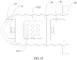
FIG. 10 is a top view after a sealing member and a heating device of the electronic cigarette ofFIG. 8 are assembled. - Embodiments of the disclosure are described more fully hereinafter with reference to the accompanying drawings. The various embodiments of the disclosure may, however, be embodied in many different forms and should not be construed as limited to the embodiments set forth herein. Rather, these embodiments are provided so that this disclosure will be thorough and complete, and will fully convey the scope of the disclosure to those skilled in the art.
- It should be noted that, when an element is described as "mounted to" another element, the element may be directly mounted on the another element, or an intermediate element may also exist; when an element is described as "connected to" another element, the element may be directly connected to the another element, or an intermediate element may also exist.
- Unless otherwise defined, all technical and scientific terms used herein have the same meaning as commonly understood by one of ordinary skill in the art to which this disclosure belongs. The terms used herein in the specification of the present disclosure are for the purpose of describing the embodiments only and are not intended to limit the invention. As used herein, the term "and/or" includes any and all combinations of one or more of the associated listed items.
- Referring to
FIG. 1 andFIG. 2 , according to a first embodiment of the present invention, anatomizer 100 is electrically connected to a battery device (not shown) to form an electronic cigarette. Theatomizer 100 is electrically driven by the battery device to heat the e-liquid, the e-liquid can be separately stored in an apparatus. The apparatus is configured to be in communication with theatomizer 100, for providing e-liquid for theatomizer 100, or, the e-liquid is directly stored in theatomizer 100, for forming smoke for user's inhaling. - The
atomizer 100 includes amain housing 10 having anopening 11 at one end, a sealingmember 30, aheating device 50, and a pair ofelectrode contact assemblies 60. Themain housing 10 defines aliquid storage chamber 13 and asmoke outlet passage 15 spaced from theliquid storage chamber 13. The sealingmember 30 is assembled to themain housing 10 via theopening 11, and the sealingmember 30 defines aliquid intake hole 31 and asmoke outlet hole 33, which are in communication with theliquid storage chamber 13 and thesmoke outlet passage 15 respectively, i.e., theliquid intake hole 31 is in communication with theliquid storage chamber 13, and thesmoke outlet hole 33 is in communication with thesmoke outlet passage 15. One side of themain housing 10 is provided with a liquid injection mark (not shown) and a sealing cover (not shown), wherein the liquid injection mark is located on a position corresponding to theliquid intake hole 31, and the sealing cover is used to seal a liquid injection hole. Theheating device 50 is assembled in the sealingmember 30, and forms anatomizing chamber 510 therein. Theatomizing chamber 510 communicates theliquid storage chamber 13 with thesmoke outlet passage 15. Exemplarily, the e-liquid stored in theliquid storage chamber 13 flows into theatomizing chamber 510 via theliquid intake hole 31, when theatomizer 100 is energized, the e-liquid flowing into theatomizing chamber 510 is atomized by theheating device 50 to form smoke, the smoke flows into thesmoke outlet passage 15 via thesmoke outlet hole 33, and under a sucking action or a pumping action, the smoke is inhaled by the user. - Specifically referring to
FIG. 2 , themain housing 10 substantially has a hollow shape, and houses the sealingmember 30 via theopening 11. Themain housing 10 defines an outlet hole on an end opposite to theopening 11, for the smoke flowing out. Themain housing 10 forms a separatingwall 17 on an inner surface, the separatingwall 17 extends along a longitudinal direction. The inner chamber of themain housing 10 is divided by the separatingwall 17 into theliquid storage chamber 13 and thesmoke outlet passage 15. According to an embodiment, both theliquid storage chamber 13 and thesmoke outlet passage 15 extend along a longitudinal direction and are parallel to each other. - The sealing
member 30 defines anaperture 35 in communication with theopening 11. In the illustrated embodiment, an end of the sealingmember 30 opposite to theaperture 35 is detachably attached on the inner wall of themain housing 10 and the separatingwall 17, and the sealingmember 30 defines theliquid intake hole 31 in communication with theliquid storage chamber 13 and thesmoke outlet hole 33 in communication withsmoke outlet passage 15. The assembly mode of the sealingmember 30 in themain housing 10 is determined according to needs, for example, by latching or interference fit, which is not limited herein, so long as the sealingmember 30 can be detachably attached to themain housing 10. - According to an embodiment, the sealing
member 30 is made of silica gel and is formed integrally by hot pressing, so that it has an elastic deformation performance, which facilitates for an assembly of the sealingmember 30 and a sealing performance is enhanced. - Specifically referring to
FIG. 1 , an end of theheating device 50 is received in the sealingmember 30, an opposite end of theheating device 50 is hermitically connected to theaperture 35, causing theheating device 50 to be hermetically assembled to themain housing 10 via the sealingmember 30. Theheating device 50 includes aheating member 530, a liquid guiding member (not shown), and abase seat 532. - Specifically, the
heating member 530 defines anairflow passage 5301 for the airflow passing through, the liquid guiding member is configured for absorbing and/or storing the e-liquid for theheating member 530 to perform an atomizing action. Both theheating member 530 and the liquid guiding member are assembled in thebase seat 532. In the illustrated embodiment, theheating member 530 is a cylindrical heating wire, and the liquid guiding member is wrapped around an outer periphery of theheating member 530. Theheating member 530 is horizontally mounted in thebase seat 532. Thebase seat 532 defines anair intake hole 5101 at an end thereof and anairflow outlet hole 5102 at an opposite end thereof, and theairflow passage 5301 is connected between theair intake hole 5101 and theairflow outlet hole 5102. - As shown in
FIG. 6 , according to an alternative embodiment, theheating member 530 can be vertically mounted in thebase seat 532. - The
base seat 532 includes afirst end 5321 received in the sealingmember 30 and asecond end 5322 hermitically connected to theaperture 35. Theatomizing chamber 510 is defined through thefirst end 5321 along an arranging direction of theliquid storage chamber 13 and thesmoke outlet passage 15. Theheating member 530 and the liquid guiding member are received in theatomizing chamber 510, and are in communication with theliquid intake hole 31, causing the e-liquid in theliquid storage chamber 13 to flow into theatomizing chamber 510 via theliquid intake hole 31. - According to an embodiment, the
first end 5321 forms a mountingprotrusion 5323 protruding in a direction away from thesecond end 5322. The mountingprotrusion 5323 is detachably assembled in theliquid intake hole 31, and defines a liquid intake aperture 5311 (as shown inFIG. 2 ) in communication with theliquid storage chamber 13 and theatomizing chamber 510, causing theheating device 50 to be detachably assembled in the sealingmember 30, theheating device 50 hermitically engages with the sealingmember 30 via thesecond end 5322. - It can be understood that, in an alternative embodiment not shown, an encapsulating member can be provided in the
liquid intake hole 31. When theheating device 50 is not assembled, due to the presence of the encapsulating member, the e-liquid in theliquid storage chamber 13 can be encapsulated. Therefore, it facilitates for transportation and replacement. When theheating device 50 is assembled in place, the mountingprotrusion 5323 can resist and pierce the encapsulating member, causing theliquid intake aperture 5311 to be in communication with theliquid intake hole 31. - In the illustrated embodiment, a cross-section of the
base seat 532 substantially has a T shape, thefirst end 5321 has a size less than that of thesecond end 5322. Thesecond end 5322 has a size matching the size of theaperture 35 of the sealingmember 30. Specifically, in the illustrated embodiment, the cross-section of thefirst end 5321 has a width less than the cross-section of thesecond end 5322. Accordingly, a smoke guiding portion 70 (as shown inFIG. 2 ) is formed between a peripheral side wall of thefirst end 5321 adjacent to thesmoke outlet passage 15 and the sealingmember 30, thesmoke guiding portion 70 is provided between and communicates thesmoke outlet passage 15 and theatomizing chamber 510, enabling the smoke generated in theatomizing chamber 510 to flow into thesmoke outlet passage 15 via thesmoke guiding portion 70, for user's inhaling. Thesmoke guiding portion 70 has a relative long passage which is perpendicular to thesmoke outlet passage 15, and this passage and thesmoke outlet passage 15 are not communicated in a straight line, to thereby form a bending portion therebetween, the atomized smoke can be blocked by the bending portion to some extent, and the e-liquid not be fully atomized can be detained in the bending portion, so that inhaling the e-liquid directly by the user can be avoided. In addition, due to the bending portion, the speed of the airflow flowing into the user's mouth is not too high, the user will not be choked by the airflow, so that the taste can further be improved. In the illustrated embodiment, theairflow passage 5301 is in communication with thesmoke outlet passage 15 via theatomizing chamber 510. It can be understood that, in an alternative embodiment not shown, theairflow passage 5301 can be in communication with thesmoke outlet passage 15 directly. - It can be concluded that, due to the
smoke guiding portion 70, an axial direction of thesmoke outlet passage 15 and an axial direction of theairflow passage 5301 defines an angle θ, and the angle θ is 90 degrees. It can be understood that, in an alternative embodiment not shown, the angle θ can be other values, that is, 0°<θ<90 degrees, or 90<θ<180 degrees. - It can be understood that, in an alternative embodiment not shown, other structures can be configured to reduce the flowing speed of the smoke. For example, one end of the
smoke guiding portion 70 in communication with theairflow passage 5301 has an internal diameter greater than an internal diameter of theairflow passage 5301. It can be understood that, the sudden increase of the internal diameter will cause a reduction of the flowing speed of the airflow. It can be understood that, each one of the aforementioned two methods for reducing the airflow speed can be selected, and alternatively, the two methods can be used at the same time. - Further, the
base seat 532 can be made from a material having a high temperature resistance and uneasy to be deformed, for example, ceramic material. Thebase seat 532 made of ceramic material can retain the atomizing temperature well, causing the taste during the next inhaling to be nearly the same as the previous inhaling. When theatomizer 100 is not used for a certain time period, thebase seat 532 made of ceramic material can absorb a part or all of the e-liquid condensed in theatomizing chamber 510. When theatomizer 100 is used again, the splashing oil can be avoided. It can be understood that, compared to other high temperature resistance materials, the ceramic material has a low cost, which facilitates for lowering down the cost. - The two
electrode contact assemblies 60 are encapsulated in opposite ends of theatomizing chamber 510, and are electrically connected to theheating member 530. Taking oneelectrode contact assembly 60 for example, one end of theelectrode contact assembly 60 serves as a part for encapsulating the atomizing chamber 510 (not encapsulating completely, this end has an annular shape, a though hole is defined in a middle for assembling theheating member 530 into the atomizing chamber 510), an opposite end extends through and protrudes out of thesecond end 5322, and is thereby electrically connected to one electrode of the battery device located out of theatomizer 100. - Referring to
FIG. 2 , preferably, themain housing 10 defines an air intake hole (not shown), the inner chamber of the air intake hole forms anair intake passage 19 in communication with an area outside theatomizer 100, and one side of the sealingmember 30 adjacent to theliquid storage chamber 11 defines anair intake opening 37 in communication with theair intake passage 19. One of the twoelectrode contact assemblies 60 adjacent to thesmoke guiding portion 70 defines a first throughhole 61 in communication with theatomizing chamber 510 and thesmoke guiding portion 70. The other one of the twoelectrode contact assemblies 60 adjacent to theair intake opening 37 defines a second throughhole 62 in communication with theair intake opening 37. After the external airflow flows into theair intake passage 19, it enters into theatomizing chamber 510 by passing through theair intake opening 37 and the second throughhole 62 successively, the airflow accompanying with the smoke formed in theatomizing chamber 510 enters into thesmoke guiding portion 70 via the first throughhole 61, the smoke in thesmoke guiding portion 70 is mixed with the external airflow and flows into thesmoke outlet passage 15 via thesmoke outlet hole 33 under a sucking action of the user, and finally, the smoke flows into user's mouth for inhaling. - Referring to
FIG. 3, FIG. 3 is a simulation diagram showing an airflow state in the atomizer of prior art. It can be seen that, the smoke atomized and formed in the airflow outlet end flows out with a high speed, the user sucks with a little force, great smoke can emerge. For user's smoke operation, it can be chocked easily due to an overload amount of smoke. Furthermore, the smoke rushes out with a high speed, and for the user, the mouth can be scalded. - Referring to
FIG. 4 andFIG. 5 , a simulation diagram of the airflow state and a simulation diagram of the aerosol flowing speed state of theatomizer 100 of the illustrated embodiment are shown respectively. It is apparently, referring toFIG. 4 , the external airflow flows into theatomizer 100, and is mixed with the smoke generated by heating and atomizing, in the flowing out process, due to thesmoke guiding portion 70, a turbulent and mixing process is existed in the airflow. In the process, the speed of the smoke is reduced, and it can retard some e-liquid particles having a larger volume which are not fully atomized and mingled in the airflow. Specifically, referring toFIG. 5 (the darker the area, the higher the airflow speed).FIG. 5 shows a simulation diagram of the airflow flowing speed state of theatomizer 100 according to the illustrated embodiment. It is apparently that, theatomizer 100 according to the embodiment has three flowing speed stages, i.e., the air intake stage, the atomizing stage and the air outlet stage. The airflow speed of the air intake stage and the airflow speed of the air outlet stage are obviously less than that of the atomizing stage, i.e., when the airflow entering into theatomizer 100 from outside passes through the atomizing stage (the heating member 532), it has a relative high speed. One advantage is that, the airflow can take away the atomized smoke rapidly, the liquid intake speed from theliquid storage chamber 13 is increased, the liquid gathering can be avoided, and the dry-burning problem can be avoided. Similarly, the flowing speed of the aerosol mixed with the smoke and the external airflow can be reduced when it encounters thesmoke guiding portion 70, it then enters into the air outlet stage, and in this stage, due to the presence of the priorsmoke guiding portion 70, the flowing speed of the aerosol can be reduced for user's normal inhaling. Because the flowing speed is not too high, the choking situation by the smoke can be reduced, the taste for the user is improved. Further, because the flowing speed of the airflow is reduced, it means that the smoke takes more time to reach the user's mouth, therefore, the smoke can be cooled to a suitable temperature, the user's mouth cannot be scalded by the smoke easily. Further, generally speaking, the flowing speed of the central airflow is greater than that of the peripheral airflow, by reducing the speed, the speeds of the internal area and the external area can remain constituent, thus the taste of the smoke can be improved. - Referring to
FIG. 2 again, in the assembly process, the end of the sealingmember 30 having theliquid intake hole 31 and thesmoke outlet hole 33 is assembled in themain housing 10 first. Theaperture 35 of the sealingmember 30 is received in theopening 11 or is coplanar with theopening 11, at this time, themain housing 10 and the sealingmember 30 are assembled together. Theheating member 530 wrapping around the liquid guiding member or theheating member 530 wrapped by the liquid guiding member is assembled into thebase seat 532, the twoelectrode contact assemblies 60 are pressed into opposite ends of theatomizing chamber 510 of thebase seat 532, respectively, at this time, theheating device 50 are assembled in the form of module. The assembledheating device 50 are assembled into themain housing 10 assembled with the sealingmember 30, the assembly of thewhole atomizer 100 is accomplished, it has a simple structure and facilitates for assembly. - The present invention further provides an electronic cigarette having the
atomizer 100. - Referring to
FIG. 7 to FIG. 10 , the third embodiment of the present invention provides anelectronic cigarette 200. Theelectronic cigarette 200 includes anatomizer 100, ahousing 80, and abattery device 90. Thebattery device 90 is received in thehousing 80 and is electrically connected to theatomizer 100. - The differences between the
atomizer 100 of the third embodiment and theatomizer 100 of the second embodiment are that: the inner wall of the air intake hole is provided with anair regulating ring 191, theair regulating ring 191 is rotatably plugged into the inner wall of the air intake hole. Theair regulating ring 191 has an annular structure. Theair regulating ring 191 is provided with anair intake portion 1911 and anoperation portion 1912 which are spaced from each other. Theair intake portion 1911 is defined through theair regulating ring 191, the inner hole of theair intake portion 1911 is in communication with the air intake hole, theoperation portion 1912 is a groove. Theair regulating ring 191 is rotated to cause theair intake portion 1911 of theair regulating ring 191 to rotate relative to the air intake hole, when theair intake portion 1911 of theair regulating ring 191 is completely staggered from the air intake hole, theair intake passage 19 is closed from the outside. When theair intake portion 1911 of theair regulating ring 191 is partially overlapped with the air intake hole, at this time, theair intake passage 19 is opened and in communication with the outside. By rotation of theoperation portion 1912 of theair regulating ring 191, an overlapping area between theair intake portion 1911 and the air intake hole can be controlled, thus an air intake volume can be adjusted. - The sealing
member 30 is plugged into the sidewall of theatomizer 100, and the sealingmember 30 can be dragged out from the sidewall of theatomizer 100. The sealingmember 30 includes abase portion 38, a blockingplate 39, a latchingplate 40, and a latching groove 44. The blockingplate 39 and the latchingplate 40 are provided on opposite ends of thebase portion 38. The latching groove 44 is recessed from a side of thebase portion 38 away from the blockingplate 39. Thebase seat 532 forms two liquid gathering chambers spaced form each other. The two gathering chambers includes a firstliquid gathering chamber 42 and a secondliquid gathering chamber 43. The blockingplate 39 is latched on thebase portion 38. The firstliquid gathering chamber 42 is formed between the blockingplate 39 and thebase portion 38. The secondliquid gathering chamber 43 is formed between the latchingplate 40 and thebase portion 38. The firstliquid gathering chamber 42 and the secondliquid gathering chamber 43 are in communication with thebase seat 532. According to an embodiment, the firstliquid gathering chamber 42 is formed after the blockingplate 39 is assembled to thebase seat 38. The secondliquid gathering chamber 43 is inherently formed due to the latchingplate 40 being integrally formed on a side of thebase portion 38. Referring toFIG. 7 , the secondliquid gathering chamber 43 is located on the smoke outlet end of an atomizing core 121, i.e., wherever the atomizing core 121 is positioned, the second liquid gatherchamber 43 on the smoke outlet end is inherently existed. Because the atomizing core 121 in the embodiment is disposed transversely, it merely atomizes the e-liquid but not sucks the smoke, the smoke may be overflowed from the left side and the right side, thus when the firstliquid gathering chamber 42 is formed after installing the blockingplate 39, the liquid gathering phenomenon on the air intake end of the atomizing core 121 can be relieved. - The
heating member 530 is received in thebase seat 532, and the liquid guiding member 531 is wrapped on theheating member 530. Thebase seat 532 further defines a liquid intake chamber (not shown) which is recessed from thebase seat 532 and in communication with theliquid storage chamber 13. The bottom of the liquid intake chamber defines a plurality ofoil guiding holes 5324 which are uniformly distributed. The bottom of the liquid intake chamber further defines two liquid intake holes 5325. The twoliquid intake holes 5325 are provided on opposite sides of the liquid intake chamber, respectively. Theliquid intake hole 5325 extends along the sidewall of the liquid intake chamber until the bottom of the liquid guiding member 531. - Referring to
FIG. 7 andFIG. 8 , theatomizer 100 is provided with a latching groove 44, thebattery device 90 is provided with anelastic latch 801 corresponding to the latching groove 44. Theatomizer 100 is fixed to thehousing 80 of theelectronic cigarette 200 by theelastic latch 801, it facilitates for assembling and disassembling, and disengagement of theatomizer 100 from thebattery device 90 can be avoided. In an alternative embodiment not shown, the positions of theelastic latch 801 and the latching groove 44 can be exchanged, i.e., theelastic latch 801 is provided on theatomizer 100, and the latching groove 44 is provided on thebattery device 90. - The
battery device 90 includes abattery housing 91, abattery 92 received in thebattery housing 91, a charginginterface 93 and an electricquantity indicator lamp 94 provided on a side of thebattery housing 91. Thebattery 92 is electrically connected to theatomizer 100, the charginginterface 93 and the electricquantity indicator lamp 94 are electrically connected to thebattery 92. Specifically, the number of the electricquantity indicator lamps 94 is five. It can be understood that, in alternative embodiment not shown, the number of the electricquantity indicator lamps 94 can be several, the several electricquantity indicator lamps 94 are uniformly distributed. The electric quantity can be observed according to the electricquantity indicator lamps 94, when the electric quantity is low, thebattery 92 can be charged by the charginginterface 93, it is convenient. - When the
electronic cigarette 200 works, by a rotation of theoperation portion 1912 of theair regulating ring 191, the overlapping area between theair intake portion 1911 and the air intake hole can be controlled, thus the air intake volume can be adjusted. As indicated by the arrows inFIG. 7 , the air is mixed with the smoke in the atomizing chamber after passing through the air intake hole and theair intake passage 19 successively, and then the air is sucked by the user after passing through thesmoke outlet passage 15 and the mouthpiece 113 successively. By defining a plurality ofoil guiding holes 5324 on thebase seat 532, so long as a negative pressure is existed in the air passage beneath theoil guiding holes 5324, the problem that the bubble generated by oil pressure or liquid intake blocks the liquid intake hole will not occur. The blockingplate 39 is latched on thebase portion 38, the blockingplate 39 and thebase portion 38 cooperatively encloses and forms the firstliquid gathering chamber 42, the secondliquid intake chamber 43 is formed between the latchingplate 40 and thebase portion 38. The blocking late 39 not only facilitates for assembling and disassembling the sealingmember 30, but also enables opposite sides of the sealingmember 30 to form the liquid gathering chambers. When the user turns on the smoking switch, but not smoke, the e-liquid is cooled rapidly to form condensed liquid, the liquid gathering chambers can be used to gather the condensed liquid and the e-liquid overflowed from the sealingmember 30, thereby preventing the condensed liquid from running anywhere. The sealingmember 30 is plugged in the sidewall of theatomizer 100, and the sealingmember 30 can be dragged out of the sidewall of theatomizer 100. When the condensed liquid is accumulated to a certain extent, the sealingmember 30 can be dragged out for cleaning. - The embodiments described above are merely preferred embodiments, but not intended to limit the disclosure. Any modifications, alternatives or improvements made within the principle of the disclosure should be interpreted as falling within the protection scope of the disclosure. The claims are not limited to the features or acts described above. Rather, the scope of the disclosure is defined by the appended claims.
Claims (24)
- A heating device, comprising a heating member, a liquid guiding member, and a base seat, wherein the heating member defines an airflow passage for airflow passing through, the liquid guiding member is configured for absorbing and/or storing e-liquid for the heating member to perform an atomizing action, both the heating member and the liquid guiding member are assembled in the base seat.
- The heating device according to claim 1, wherein the base seat is made of ceramic material.
- The heating device according to claim 1 or 2, wherein the heating member is a cylindrical heating wire, and the liquid guiding member is wrapped around an outer periphery of the heating member, the heating member is horizontally mounted in the base seat, or the heating member is vertically mounted in the base seat.
- The heating device according to claim 1 or 2, wherein the base seat defines an air intake hole on one end and an airflow outlet hole on an opposite end, the airflow passage is connected between the air intake hole and airflow outlet hole.
- The heating device according to claim 1, wherein the base seat forms an air intake end and a smoke outlet end which are oppositely disposed, the smoke outlet end of the base seat forms a liquid gathering chamber, the heating member forms a smoke generating passage therein, the smoke generating passage of the heating member is in communication with the liquid gathering chamber.
- The heating device according to claim 5, wherein the liquid gathering chamber of the smoke outlet end of the base seat is a first liquid gathering chamber, the air intake end of the base seat is further provided with a detachable second liquid gathering chamber.
- The heating device according to claim 6, wherein the base seat comprises a base portion, a blocking plate and a latching plate, the blocking plate and the latching plate are provided on opposite ends of the base portion, the blocking plate is detachably provided on the air intake end of the base seat, the first liquid gathering chamber is formed between the latching plate and the base portion, the second liquid gathering chamber is formed between the blocking plate and the base portion.
- The heating device according to claim 7, wherein the base portion is recessed to form a liquid intake chamber, a bottom of the liquid intake chamber defines a plurality of oil guiding holes which are uniformly distributed, the plurality of oil guiding holes are in communication with the liquid guiding member.
- The heating device according to claim 8, wherein the bottom of the liquid intake chamber further defines a liquid intake hole, the liquid intake hole is positioned on a side of the bottom of the liquid intake chamber, the liquid intake hole extends to a bottom of the liquid guiding member.
- An atomizer, comprising a heating device and a pair of electrode contact assemblies for providing electrical driving for the heating device, wherein the heating device is a heating device according to any one of claims 1 to 9.
- The atomizer according to claim 10, wherein the atomizer further comprises a sealing member and a main housing having an opening at one end, the main housing defines therein a liquid storage chamber and a smoke outlet passage, the sealing member is assembled to the main housing via the opening, the sealing member defines a liquid intake hole and a smoke outlet hole which are in communication with the liquid storage chamber and the smoke outlet passage, respectively, one side of the main housing is provided with a liquid injection mark and a sealing cover, the liquid injection mark is located on a position corresponding to the liquid intake hole, the sealing cover is used to seal a liquid injection hole, the heating device is assembled in the sealing member, the base seat forms an atomizing chamber therein, the atomizing chamber communicates the liquid storage chamber and the smoke outlet passage.
- The atomizer according to claim 11, wherein the smoke outlet passage is parallel to the liquid storage chamber, the sealing member defines an aperture in communication with the opening, one end of the heating device is received in the sealing member, an opposite end of the heating device is hermetically connected to the aperture.
- The atomizer according to claim 6, wherein the smoke outlet passage is in communication with the airflow passage via a smoke guiding portion.
- The atomizer according to claim 11, wherein an axial direction of the smoke outlet passage and an axial direction of the airflow passage forms an angle θ via the smoke guiding portion, the angle θ has a value selected from 0<θ<180 degrees.
- The atomizer according to claim 13 or 14, wherein one end of the smoke guiding portion in communication with the airflow passage has an internal diameter greater than an internal diameter of the airflow passage.
- The atomizer according to claim 15, wherein the smoke guiding portion is provided between the sealing member and a peripheral side wall of the base seat adjacent to the smoke outlet passage, and communicates the smoke outlet passage and the atomizing chamber, one of the two electrode contact assemblies adjacent to the smoke guiding portion defines a first through hole communicating the atomizing chamber and the smoke guiding portion.
- The atomizer according to claim 10, wherein the base seat comprises a first end received in the sealing member and a second end hermitically connected to the aperture, the atomizing chamber is defined through the first end along an arranging direction of the liquid storage chamber and the smoke outlet passage, the heating member and the liquid guiding member are received in the atomizing chamber, and are aligned with and in communication with the liquid intake hole.
- The atomizer according to claim 17, wherein the first end forms a mounting protrusion protruding in a direction away from the second end, the mounting protrusion is detachably assembled in the liquid intake hole and defines a liquid intake aperture communicating the liquid storage chamber and the atomizing chamber.
- The atomizer according to claim 17, wherein the heating member wrapping around the liquid guiding member or the heating member wrapped by the liquid guiding member is assembled in the atomizing chamber, one end of the two electrode contact assemblies are encapsulated in opposite ends of the atomizing chamber and are electrically connected to the heating member, an opposite end of the two electrode contact assemblies extends through and protrudes out of the first end.
- The atomizer according to claim 11, wherein the main housing defines an air intake hole, an inner chamber of the air intake hole forms an air intake passage, one side of the sealing member adjacent to the liquid storage chamber defines an air intake opening in communication with the air intake passage, one of the two electrode contact assemblies adjacent to the air intake opening defines a second through hole in communication with the air intake opening.
- The atomizer according to claim 11, wherein the sealing member is made of silica gel.
- The atomizer according to claim 20, wherein an inner wall of the air intake hole is provided with an air regulating ring, the regulating ring is plugged into the inner wall of the air intake hole, the air regulating ring is provided with an air intake portion and an operation portion which are spaced from each other, the air intake portion is defined through the air regulating ring, and an inner hole of the air intake portion is in communication with the air intake hole.
- An electronic cigarette, comprising an atomizer and a battery device electrically connected to the atomizer, wherein the atomizer is an atomizer according to any one of claim 10 to 21.
- The electronic cigarette according to claim 23, wherein the battery device or the atomizer is provided with an elastic latch, the atomizer or the battery device defines a latching groove correspondingly, for securing the atomizer to the battery device.
Applications Claiming Priority (2)
| Application Number | Priority Date | Filing Date | Title |
|---|---|---|---|
| CN201720392995 | 2017-04-14 | ||
| PCT/CN2017/114001 WO2018188353A1 (en) | 2017-04-14 | 2017-11-30 | Heating device, atomizer and electronic cigarette |
Publications (3)
| Publication Number | Publication Date |
|---|---|
| EP3610737A1 true EP3610737A1 (en) | 2020-02-19 |
| EP3610737A4 EP3610737A4 (en) | 2021-03-03 |
| EP3610737B1 EP3610737B1 (en) | 2024-03-13 |
Family
ID=63792293
Family Applications (1)
| Application Number | Title | Priority Date | Filing Date |
|---|---|---|---|
| EP17905340.0A Active EP3610737B1 (en) | 2017-04-14 | 2017-11-30 | Heating device, atomizer and electronic cigarette |
Country Status (4)
| Country | Link |
|---|---|
| US (1) | US11297881B2 (en) |
| EP (1) | EP3610737B1 (en) |
| CN (3) | CN109068744B (en) |
| WO (2) | WO2018188231A1 (en) |
Families Citing this family (38)
| Publication number | Priority date | Publication date | Assignee | Title |
|---|---|---|---|---|
| GB201617246D0 (en) * | 2016-10-11 | 2016-11-23 | British American Tobacco (Investments) Limited | Aerosol provision system and method |
| CA3037639C (en) | 2016-11-29 | 2021-03-09 | Philip Morris Products S.A. | Aerosol-generating system with adjustable pump flow rate |
| US12048329B2 (en) * | 2018-09-14 | 2024-07-30 | Imperial Tobacco Limited | Consumable for a smoking substitute device |
| CN209420955U (en) * | 2018-11-14 | 2019-09-24 | 常州市派腾电子技术服务有限公司 | an electronic cigarette |
| CN109619707B (en) * | 2019-02-27 | 2023-11-10 | 凤凰爱嗨科技有限公司 | Oil leakage prevention atomization pumping device |
| CN116807063A (en) * | 2019-03-13 | 2023-09-29 | 常州市派腾电子技术服务有限公司 | Cartridge and electronic cigarette |
| CN111685373B (en) * | 2019-03-13 | 2025-07-18 | 常州市派腾电子技术服务有限公司 | Cartridges and electronic cigarettes |
| CN111820460B (en) * | 2019-04-15 | 2025-03-21 | 湖南中烟工业有限责任公司 | Low-temperature baking smoking utensils that take in air from the side of the cigarette |
| JP7291249B2 (en) * | 2019-05-14 | 2023-06-14 | 深▲せん▼麦克韋爾科技有限公司 | Nebulizers and electronic nebulizers |
| CN110074464B (en) * | 2019-05-15 | 2024-04-16 | 深圳市你我网络科技有限公司 | Atomizer and electronic cigarette |
| CN111955802A (en) * | 2019-05-20 | 2020-11-20 | 深圳市康特客科技有限公司 | Electronic cigarette with U-shaped airflow channel atomizer assembly and using method thereof |
| CN110025055B (en) * | 2019-05-30 | 2024-09-03 | 深圳市庚诚达科技有限公司 | Atomizing device, atomizer and electronic cigarette |
| CN110250578A (en) | 2019-06-24 | 2019-09-20 | 深圳市合元科技有限公司 | Atomizing component and electronic cigarette |
| CN110226779A (en) * | 2019-06-27 | 2019-09-13 | 深圳雾芯科技有限公司 | Electronic atomizer and electronic atomizer device |
| CN110664017B (en) * | 2019-11-05 | 2022-08-16 | 深圳市新宜康科技股份有限公司 | Method for alternately heating multiple heating bodies of atomizer and atomizer |
| CN111165880B (en) * | 2019-11-22 | 2024-08-30 | 深圳市你我网络科技有限公司 | Atomizer |
| CN111165883B (en) * | 2019-12-31 | 2025-08-12 | 深圳市斯科尔科技股份有限公司 | Atomizing device of electronic cigarette and electronic cigarette |
| CN111011937B (en) * | 2019-12-31 | 2025-05-30 | 深圳瀚星翔科技有限公司 | Electronic cigarette and atomization device |
| CN111329115B (en) * | 2020-03-04 | 2025-03-14 | 深圳麦克韦尔科技有限公司 | Atomizer and electronic atomizer device |
| EP3973798B1 (en) * | 2020-06-09 | 2025-07-30 | Shenzhen Huachengda Precision Industry Co., Ltd. | Liquid recycling atomization device |
| CN111657558B (en) * | 2020-06-24 | 2021-07-30 | 湖南湘鑫港新材料科技有限公司 | Novel ceramic atomizing core |
| ES2965016T3 (en) * | 2020-08-25 | 2024-04-10 | Shenzhen Huachengda Prec Industry Co Ltd | Atomization unit with a tortuous air passage and atomization assembly |
| EP4210523A1 (en) * | 2020-09-08 | 2023-07-19 | JT International SA | Heater device component |
| CN112704272A (en) * | 2020-11-20 | 2021-04-27 | 深圳市施美乐科技股份有限公司 | Electronic atomization device, atomizer, atomization core assembly, heating assembly and operation method of atomizer |
| CN112471600B (en) * | 2020-11-25 | 2025-08-08 | 深圳麦克韦尔科技有限公司 | Atomizers and electronic atomization devices |
| KR102533270B1 (en) * | 2021-04-29 | 2023-05-15 | 주식회사 케이티앤지 | Cartridges and device for generating aerosol including the same |
| CN115336794B (en) * | 2021-05-12 | 2025-08-08 | 深圳麦克韦尔科技有限公司 | Atomizer and electronic atomization device thereof |
| CN215347062U (en) * | 2021-06-04 | 2021-12-31 | 比亚迪精密制造有限公司 | Electronic cigarette atomizing device and electronic cigarette |
| KR102545834B1 (en) * | 2021-06-25 | 2023-06-20 | 주식회사 케이티앤지 | Cartridges and device for generating aerosol including the same |
| CN113598426A (en) * | 2021-07-30 | 2021-11-05 | 深圳麦克韦尔科技有限公司 | Heating module and electronic atomization device |
| US12575606B2 (en) | 2021-08-13 | 2026-03-17 | Kt&G Corporation | Aerosol generating device comprising a cartridge |
| CN114098168B (en) * | 2021-12-08 | 2025-11-21 | 深圳易佳特科技有限公司 | Heating element, atomizer and electronic cigarette |
| CN116326819B (en) * | 2021-12-22 | 2025-08-01 | 云南喜科科技有限公司 | Multifunctional device Aerosol generating article |
| CN116406847A (en) * | 2021-12-30 | 2023-07-11 | 深圳麦克韦尔科技有限公司 | Atomizers and Electronic Atomization Devices |
| CN116491693A (en) * | 2022-01-21 | 2023-07-28 | 深圳市卓力能技术有限公司 | a nebulizer |
| CN217986687U (en) | 2022-03-29 | 2022-12-09 | 比亚迪精密制造有限公司 | Electronic cigarette atomization assembly and electronic cigarette |
| CN115989903A (en) * | 2023-01-29 | 2023-04-21 | 深圳麦克韦尔科技有限公司 | Power supply device and aerosol generating device |
| US12207686B1 (en) | 2024-09-06 | 2025-01-28 | My Next Idea, LLC | Vortexer for cap of personal vaporizer |
Family Cites Families (31)
| Publication number | Priority date | Publication date | Assignee | Title |
|---|---|---|---|---|
| AT507187B1 (en) * | 2008-10-23 | 2010-03-15 | Helmut Dr Buchberger | INHALER |
| US9854839B2 (en) | 2012-01-31 | 2018-01-02 | Altria Client Services Llc | Electronic vaping device and method |
| WO2013159245A1 (en) * | 2012-04-26 | 2013-10-31 | Ruyan Investment (Holdings) Limited | Electronic cigarette with sealed cartridge |
| CN203105624U (en) * | 2013-01-28 | 2013-08-07 | 卓尔悦(常州)电子科技有限公司 | Electronic cigarette atomizer |
| US9861138B2 (en) * | 2013-01-31 | 2018-01-09 | Huizhou Kimree Technology Co., Ltd., Shenzhen Branch | Electronic cigarette and its sucking rod |
| CN204540812U (en) * | 2013-03-27 | 2015-08-12 | 吉瑞高新科技股份有限公司 | Electronic cigarette |
| CN203435687U (en) * | 2013-08-31 | 2014-02-19 | 卓尔悦(常州)电子科技有限公司 | Atomizing head |
| CN103932401B (en) * | 2013-09-29 | 2015-09-30 | 深圳麦克韦尔股份有限公司 | Electronic cigarette |
| US20150136158A1 (en) * | 2013-11-15 | 2015-05-21 | Jj 206, Llc | Systems and methods for a vaporization device and product usage control and documentation |
| CN106455696B (en) * | 2014-05-28 | 2020-01-10 | 吉瑞高新科技股份有限公司 | Electronic cigarette and air inflow adjusting method thereof |
| CN204232300U (en) * | 2014-10-31 | 2015-04-01 | 惠州市吉瑞科技有限公司 | Disposable electric cigarette |
| WO2016095220A1 (en) * | 2014-12-19 | 2016-06-23 | 深圳麦克韦尔股份有限公司 | Electronic cigarette and atomization device thereof |
| CN104544570B (en) * | 2014-12-31 | 2017-12-08 | 深圳麦克韦尔股份有限公司 | Inhalator and its atomizing component |
| CN204466907U (en) * | 2015-02-02 | 2015-07-15 | 深圳市麦克韦尔科技有限公司 | Inhalator and atomizing component thereof |
| KR101524997B1 (en) * | 2015-02-27 | 2015-06-03 | 김창유 | Modular electronic cigarettes heating structure and electronic cigarettes having the same |
| CN204483030U (en) * | 2015-03-18 | 2015-07-22 | 卓尔悦(常州)电子科技有限公司 | Atomizer and electronic cigarette thereof |
| CN105212278B (en) * | 2015-10-28 | 2019-03-22 | 深圳麦克韦尔股份有限公司 | Electronic smoke atomizer |
| CN105433443A (en) * | 2015-12-25 | 2016-03-30 | 深圳市合元科技有限公司 | Atomizer and electronic smoking device |
| CN105476073B (en) * | 2016-01-18 | 2018-01-02 | 湖北中烟工业有限责任公司 | Bilateral feed flow formula Atmized electronic cigarrette |
| CN105559146B (en) * | 2016-02-01 | 2018-08-24 | 昂纳自动化技术(深圳)有限公司 | A kind of electronic cigarette equipped with multiple heat generating components |
| CN105559149B (en) * | 2016-03-11 | 2018-06-19 | 深圳市赛尔美电子科技有限公司 | Tobacco flue-curing device |
| CN105982364A (en) * | 2016-04-29 | 2016-10-05 | 湖南中烟工业有限责任公司 | Atomizer and electronic cigarette |
| CN105768236B (en) * | 2016-05-06 | 2019-04-26 | 卓尔悦欧洲控股有限公司 | Atomizer and its electronic cigarette |
| CN205728055U (en) * | 2016-05-06 | 2016-11-30 | 卓尔悦欧洲控股有限公司 | Atomising head, atomising device and electronic cigarette |
| CN205757193U (en) | 2016-06-02 | 2016-12-07 | 卓尔悦欧洲控股有限公司 | A kind of cigarette holder and include its nebulizer, electronic cigarette |
| US10188146B2 (en) * | 2016-06-28 | 2019-01-29 | Shenzhen Smoore Technology Limited | Electronic cigarette and atomizer device and atomizer assembly thereof |
| CN106072767B (en) * | 2016-06-28 | 2019-04-02 | 卓尔悦欧洲控股有限公司 | Atomising head, atomizer and its electronic cigarette |
| CN106418709B (en) * | 2016-10-10 | 2023-08-08 | 深圳市康泓威科技有限公司 | Electronic cigarette with horizontal liquid supply |
| CN206150466U (en) * | 2016-11-11 | 2017-05-10 | 周成龙 | Electronic cigarette |
| US11191303B2 (en) * | 2018-03-30 | 2021-12-07 | Shenzhen First Union Technology Co., Ltd. | Atomizer and electronic cigarette having same |
| US11825883B2 (en) * | 2018-07-16 | 2023-11-28 | Lubby Holdings, LLC | Personal vaporizer |
-
2017
- 2017-08-03 CN CN201780025190.4A patent/CN109068744B/en active Active
- 2017-08-03 WO PCT/CN2017/095860 patent/WO2018188231A1/en not_active Ceased
- 2017-11-30 CN CN201780026298.5A patent/CN109195461B/en not_active Expired - Fee Related
- 2017-11-30 CN CN201721655386.5U patent/CN208228301U/en not_active Expired - Fee Related
- 2017-11-30 WO PCT/CN2017/114001 patent/WO2018188353A1/en not_active Ceased
- 2017-11-30 US US16/604,926 patent/US11297881B2/en active Active
- 2017-11-30 EP EP17905340.0A patent/EP3610737B1/en active Active
Also Published As
| Publication number | Publication date |
|---|---|
| EP3610737A4 (en) | 2021-03-03 |
| US11297881B2 (en) | 2022-04-12 |
| EP3610737B1 (en) | 2024-03-13 |
| CN109195461A (en) | 2019-01-11 |
| WO2018188231A1 (en) | 2018-10-18 |
| CN109068744A (en) | 2018-12-21 |
| US20200163381A1 (en) | 2020-05-28 |
| CN109068744B (en) | 2021-07-02 |
| CN109195461B (en) | 2021-07-02 |
| CN208228301U (en) | 2018-12-14 |
| WO2018188353A1 (en) | 2018-10-18 |
Similar Documents
| Publication | Publication Date | Title |
|---|---|---|
| EP3610737B1 (en) | Heating device, atomizer and electronic cigarette | |
| US10292432B2 (en) | Electronic cigarette | |
| KR102215396B1 (en) | Ultrasonic electronic cigarette atomizer and electronic cigarette | |
| CN206453243U (en) | Cigarette bullet, atomizing component and its electronic cigarette | |
| CN107951075B (en) | Electronic atomizer | |
| CN205567822U (en) | Two electron cigarettes of sending out atomizing core in area | |
| CN204169056U (en) | Atomizing component and electronic cigarette | |
| CN215455369U (en) | Electronic cigarette with function of preventing smoke oil and condensate leakage | |
| CN109330038B (en) | Atomizers and Electronic Cigarettes | |
| CN219803342U (en) | Atomizer and atomizing equipment | |
| CN219125369U (en) | Atomization device and electronic cigarette | |
| WO2018112769A1 (en) | Atomizer | |
| CN110313640A (en) | Atomizing component and electronic cigarette | |
| CN219479221U (en) | Aerosol generating device | |
| CN215684793U (en) | Electronic cigarette with cigarette bullet cap | |
| CN212971667U (en) | Atomizer with pneumatic switch arranged on top | |
| CN211091863U (en) | Electronic cigarette and its atomizer | |
| WO2018170829A1 (en) | Atomizer | |
| CN219125368U (en) | Atomization device and electronic cigarette | |
| CN111685382A (en) | Atomizer and electronic cigarette | |
| CN217743151U (en) | Aerosol generating device | |
| EP3981269B1 (en) | Atomizing core and atomizer of electronic cigarette | |
| CN216293021U (en) | Electronic atomizer | |
| CN216493489U (en) | Electronic cigarette atomization assembly and electronic cigarette | |
| CN110558627B (en) | Electronic cigarette, atomizer and electrode connection structure thereof |
Legal Events
| Date | Code | Title | Description |
|---|---|---|---|
| STAA | Information on the status of an ep patent application or granted ep patent |
Free format text: STATUS: THE INTERNATIONAL PUBLICATION HAS BEEN MADE |
|
| PUAI | Public reference made under article 153(3) epc to a published international application that has entered the european phase |
Free format text: ORIGINAL CODE: 0009012 |
|
| STAA | Information on the status of an ep patent application or granted ep patent |
Free format text: STATUS: REQUEST FOR EXAMINATION WAS MADE |
|
| 17P | Request for examination filed |
Effective date: 20191114 |
|
| AK | Designated contracting states |
Kind code of ref document: A1 Designated state(s): AL AT BE BG CH CY CZ DE DK EE ES FI FR GB GR HR HU IE IS IT LI LT LU LV MC MK MT NL NO PL PT RO RS SE SI SK SM TR |
|
| AX | Request for extension of the european patent |
Extension state: BA ME |
|
| DAV | Request for validation of the european patent (deleted) | ||
| DAX | Request for extension of the european patent (deleted) | ||
| A4 | Supplementary search report drawn up and despatched |
Effective date: 20210201 |
|
| RIC1 | Information provided on ipc code assigned before grant |
Ipc: A24F 40/485 20200101ALI20210126BHEP Ipc: A24F 40/46 20200101AFI20210126BHEP |
|
| REG | Reference to a national code |
Ref country code: DE Ref legal event code: R079 Free format text: PREVIOUS MAIN CLASS: A24F0047000000 Ipc: A24F0040460000 Ref country code: DE Ref legal event code: R079 Ref document number: 602017080099 Country of ref document: DE Free format text: PREVIOUS MAIN CLASS: A24F0047000000 Ipc: A24F0040460000 |
|
| RIC1 | Information provided on ipc code assigned before grant |
Ipc: A24F 40/10 20200101ALN20230906BHEP Ipc: A24F 40/485 20200101ALI20230906BHEP Ipc: A24F 40/46 20200101AFI20230906BHEP |
|
| GRAP | Despatch of communication of intention to grant a patent |
Free format text: ORIGINAL CODE: EPIDOSNIGR1 |
|
| STAA | Information on the status of an ep patent application or granted ep patent |
Free format text: STATUS: GRANT OF PATENT IS INTENDED |
|
| INTG | Intention to grant announced |
Effective date: 20231017 |
|
| GRAS | Grant fee paid |
Free format text: ORIGINAL CODE: EPIDOSNIGR3 |
|
| GRAA | (expected) grant |
Free format text: ORIGINAL CODE: 0009210 |
|
| STAA | Information on the status of an ep patent application or granted ep patent |
Free format text: STATUS: THE PATENT HAS BEEN GRANTED |
|
| P01 | Opt-out of the competence of the unified patent court (upc) registered |
Effective date: 20240124 |
|
| AK | Designated contracting states |
Kind code of ref document: B1 Designated state(s): AL AT BE BG CH CY CZ DE DK EE ES FI FR GB GR HR HU IE IS IT LI LT LU LV MC MK MT NL NO PL PT RO RS SE SI SK SM TR |
|
| REG | Reference to a national code |
Ref country code: GB Ref legal event code: FG4D |
|
| REG | Reference to a national code |
Ref country code: CH Ref legal event code: EP |
|
| REG | Reference to a national code |
Ref country code: DE Ref legal event code: R096 Ref document number: 602017080099 Country of ref document: DE |
|
| REG | Reference to a national code |
Ref country code: IE Ref legal event code: FG4D |
|
| PG25 | Lapsed in a contracting state [announced via postgrant information from national office to epo] |
Ref country code: LT Free format text: LAPSE BECAUSE OF FAILURE TO SUBMIT A TRANSLATION OF THE DESCRIPTION OR TO PAY THE FEE WITHIN THE PRESCRIBED TIME-LIMIT Effective date: 20240313 |
|
| REG | Reference to a national code |
Ref country code: LT Ref legal event code: MG9D |
|
| PG25 | Lapsed in a contracting state [announced via postgrant information from national office to epo] |
Ref country code: GR Free format text: LAPSE BECAUSE OF FAILURE TO SUBMIT A TRANSLATION OF THE DESCRIPTION OR TO PAY THE FEE WITHIN THE PRESCRIBED TIME-LIMIT Effective date: 20240614 |
|
| REG | Reference to a national code |
Ref country code: NL Ref legal event code: MP Effective date: 20240313 |
|
| PG25 | Lapsed in a contracting state [announced via postgrant information from national office to epo] |
Ref country code: RS Free format text: LAPSE BECAUSE OF FAILURE TO SUBMIT A TRANSLATION OF THE DESCRIPTION OR TO PAY THE FEE WITHIN THE PRESCRIBED TIME-LIMIT Effective date: 20240613 Ref country code: HR Free format text: LAPSE BECAUSE OF FAILURE TO SUBMIT A TRANSLATION OF THE DESCRIPTION OR TO PAY THE FEE WITHIN THE PRESCRIBED TIME-LIMIT Effective date: 20240313 |
|
| PG25 | Lapsed in a contracting state [announced via postgrant information from national office to epo] |
Ref country code: ES Free format text: LAPSE BECAUSE OF FAILURE TO SUBMIT A TRANSLATION OF THE DESCRIPTION OR TO PAY THE FEE WITHIN THE PRESCRIBED TIME-LIMIT Effective date: 20240313 |
|
| PG25 | Lapsed in a contracting state [announced via postgrant information from national office to epo] |
Ref country code: RS Free format text: LAPSE BECAUSE OF FAILURE TO SUBMIT A TRANSLATION OF THE DESCRIPTION OR TO PAY THE FEE WITHIN THE PRESCRIBED TIME-LIMIT Effective date: 20240613 Ref country code: NO Free format text: LAPSE BECAUSE OF FAILURE TO SUBMIT A TRANSLATION OF THE DESCRIPTION OR TO PAY THE FEE WITHIN THE PRESCRIBED TIME-LIMIT Effective date: 20240613 Ref country code: LT Free format text: LAPSE BECAUSE OF FAILURE TO SUBMIT A TRANSLATION OF THE DESCRIPTION OR TO PAY THE FEE WITHIN THE PRESCRIBED TIME-LIMIT Effective date: 20240313 Ref country code: HR Free format text: LAPSE BECAUSE OF FAILURE TO SUBMIT A TRANSLATION OF THE DESCRIPTION OR TO PAY THE FEE WITHIN THE PRESCRIBED TIME-LIMIT Effective date: 20240313 Ref country code: GR Free format text: LAPSE BECAUSE OF FAILURE TO SUBMIT A TRANSLATION OF THE DESCRIPTION OR TO PAY THE FEE WITHIN THE PRESCRIBED TIME-LIMIT Effective date: 20240614 Ref country code: FI Free format text: LAPSE BECAUSE OF FAILURE TO SUBMIT A TRANSLATION OF THE DESCRIPTION OR TO PAY THE FEE WITHIN THE PRESCRIBED TIME-LIMIT Effective date: 20240313 Ref country code: ES Free format text: LAPSE BECAUSE OF FAILURE TO SUBMIT A TRANSLATION OF THE DESCRIPTION OR TO PAY THE FEE WITHIN THE PRESCRIBED TIME-LIMIT Effective date: 20240313 Ref country code: BG Free format text: LAPSE BECAUSE OF FAILURE TO SUBMIT A TRANSLATION OF THE DESCRIPTION OR TO PAY THE FEE WITHIN THE PRESCRIBED TIME-LIMIT Effective date: 20240313 |
|
| REG | Reference to a national code |
Ref country code: AT Ref legal event code: MK05 Ref document number: 1664877 Country of ref document: AT Kind code of ref document: T Effective date: 20240313 |
|
| PG25 | Lapsed in a contracting state [announced via postgrant information from national office to epo] |
Ref country code: SE Free format text: LAPSE BECAUSE OF FAILURE TO SUBMIT A TRANSLATION OF THE DESCRIPTION OR TO PAY THE FEE WITHIN THE PRESCRIBED TIME-LIMIT Effective date: 20240313 Ref country code: LV Free format text: LAPSE BECAUSE OF FAILURE TO SUBMIT A TRANSLATION OF THE DESCRIPTION OR TO PAY THE FEE WITHIN THE PRESCRIBED TIME-LIMIT Effective date: 20240313 |
|
| PG25 | Lapsed in a contracting state [announced via postgrant information from national office to epo] |
Ref country code: NL Free format text: LAPSE BECAUSE OF FAILURE TO SUBMIT A TRANSLATION OF THE DESCRIPTION OR TO PAY THE FEE WITHIN THE PRESCRIBED TIME-LIMIT Effective date: 20240313 |
|
| PG25 | Lapsed in a contracting state [announced via postgrant information from national office to epo] |
Ref country code: NL Free format text: LAPSE BECAUSE OF FAILURE TO SUBMIT A TRANSLATION OF THE DESCRIPTION OR TO PAY THE FEE WITHIN THE PRESCRIBED TIME-LIMIT Effective date: 20240313 |
|
| PG25 | Lapsed in a contracting state [announced via postgrant information from national office to epo] |
Ref country code: IS Free format text: LAPSE BECAUSE OF FAILURE TO SUBMIT A TRANSLATION OF THE DESCRIPTION OR TO PAY THE FEE WITHIN THE PRESCRIBED TIME-LIMIT Effective date: 20240713 |
|
| PG25 | Lapsed in a contracting state [announced via postgrant information from national office to epo] |
Ref country code: SM Free format text: LAPSE BECAUSE OF FAILURE TO SUBMIT A TRANSLATION OF THE DESCRIPTION OR TO PAY THE FEE WITHIN THE PRESCRIBED TIME-LIMIT Effective date: 20240313 Ref country code: PT Free format text: LAPSE BECAUSE OF FAILURE TO SUBMIT A TRANSLATION OF THE DESCRIPTION OR TO PAY THE FEE WITHIN THE PRESCRIBED TIME-LIMIT Effective date: 20240715 |
|
| PG25 | Lapsed in a contracting state [announced via postgrant information from national office to epo] |
Ref country code: EE Free format text: LAPSE BECAUSE OF FAILURE TO SUBMIT A TRANSLATION OF THE DESCRIPTION OR TO PAY THE FEE WITHIN THE PRESCRIBED TIME-LIMIT Effective date: 20240313 Ref country code: CZ Free format text: LAPSE BECAUSE OF FAILURE TO SUBMIT A TRANSLATION OF THE DESCRIPTION OR TO PAY THE FEE WITHIN THE PRESCRIBED TIME-LIMIT Effective date: 20240313 |
|
| PG25 | Lapsed in a contracting state [announced via postgrant information from national office to epo] |
Ref country code: AT Free format text: LAPSE BECAUSE OF FAILURE TO SUBMIT A TRANSLATION OF THE DESCRIPTION OR TO PAY THE FEE WITHIN THE PRESCRIBED TIME-LIMIT Effective date: 20240313 |
|
| PG25 | Lapsed in a contracting state [announced via postgrant information from national office to epo] |
Ref country code: PL Free format text: LAPSE BECAUSE OF FAILURE TO SUBMIT A TRANSLATION OF THE DESCRIPTION OR TO PAY THE FEE WITHIN THE PRESCRIBED TIME-LIMIT Effective date: 20240313 |
|
| PG25 | Lapsed in a contracting state [announced via postgrant information from national office to epo] |
Ref country code: SK Free format text: LAPSE BECAUSE OF FAILURE TO SUBMIT A TRANSLATION OF THE DESCRIPTION OR TO PAY THE FEE WITHIN THE PRESCRIBED TIME-LIMIT Effective date: 20240313 |
|
| PG25 | Lapsed in a contracting state [announced via postgrant information from national office to epo] |
Ref country code: SM Free format text: LAPSE BECAUSE OF FAILURE TO SUBMIT A TRANSLATION OF THE DESCRIPTION OR TO PAY THE FEE WITHIN THE PRESCRIBED TIME-LIMIT Effective date: 20240313 Ref country code: SK Free format text: LAPSE BECAUSE OF FAILURE TO SUBMIT A TRANSLATION OF THE DESCRIPTION OR TO PAY THE FEE WITHIN THE PRESCRIBED TIME-LIMIT Effective date: 20240313 Ref country code: RO Free format text: LAPSE BECAUSE OF FAILURE TO SUBMIT A TRANSLATION OF THE DESCRIPTION OR TO PAY THE FEE WITHIN THE PRESCRIBED TIME-LIMIT Effective date: 20240313 Ref country code: PT Free format text: LAPSE BECAUSE OF FAILURE TO SUBMIT A TRANSLATION OF THE DESCRIPTION OR TO PAY THE FEE WITHIN THE PRESCRIBED TIME-LIMIT Effective date: 20240715 Ref country code: PL Free format text: LAPSE BECAUSE OF FAILURE TO SUBMIT A TRANSLATION OF THE DESCRIPTION OR TO PAY THE FEE WITHIN THE PRESCRIBED TIME-LIMIT Effective date: 20240313 Ref country code: IS Free format text: LAPSE BECAUSE OF FAILURE TO SUBMIT A TRANSLATION OF THE DESCRIPTION OR TO PAY THE FEE WITHIN THE PRESCRIBED TIME-LIMIT Effective date: 20240713 Ref country code: EE Free format text: LAPSE BECAUSE OF FAILURE TO SUBMIT A TRANSLATION OF THE DESCRIPTION OR TO PAY THE FEE WITHIN THE PRESCRIBED TIME-LIMIT Effective date: 20240313 Ref country code: CZ Free format text: LAPSE BECAUSE OF FAILURE TO SUBMIT A TRANSLATION OF THE DESCRIPTION OR TO PAY THE FEE WITHIN THE PRESCRIBED TIME-LIMIT Effective date: 20240313 Ref country code: AT Free format text: LAPSE BECAUSE OF FAILURE TO SUBMIT A TRANSLATION OF THE DESCRIPTION OR TO PAY THE FEE WITHIN THE PRESCRIBED TIME-LIMIT Effective date: 20240313 |
|
| PG25 | Lapsed in a contracting state [announced via postgrant information from national office to epo] |
Ref country code: IT Free format text: LAPSE BECAUSE OF FAILURE TO SUBMIT A TRANSLATION OF THE DESCRIPTION OR TO PAY THE FEE WITHIN THE PRESCRIBED TIME-LIMIT Effective date: 20240313 |
|
| REG | Reference to a national code |
Ref country code: DE Ref legal event code: R097 Ref document number: 602017080099 Country of ref document: DE |
|
| PG25 | Lapsed in a contracting state [announced via postgrant information from national office to epo] |
Ref country code: IT Free format text: LAPSE BECAUSE OF FAILURE TO SUBMIT A TRANSLATION OF THE DESCRIPTION OR TO PAY THE FEE WITHIN THE PRESCRIBED TIME-LIMIT Effective date: 20240313 |
|
| PG25 | Lapsed in a contracting state [announced via postgrant information from national office to epo] |
Ref country code: DK Free format text: LAPSE BECAUSE OF FAILURE TO SUBMIT A TRANSLATION OF THE DESCRIPTION OR TO PAY THE FEE WITHIN THE PRESCRIBED TIME-LIMIT Effective date: 20240313 |
|
| PLBE | No opposition filed within time limit |
Free format text: ORIGINAL CODE: 0009261 |
|
| STAA | Information on the status of an ep patent application or granted ep patent |
Free format text: STATUS: NO OPPOSITION FILED WITHIN TIME LIMIT |
|
| PGFP | Annual fee paid to national office [announced via postgrant information from national office to epo] |
Ref country code: FR Payment date: 20241120 Year of fee payment: 8 |
|
| PG25 | Lapsed in a contracting state [announced via postgrant information from national office to epo] |
Ref country code: DK Free format text: LAPSE BECAUSE OF FAILURE TO SUBMIT A TRANSLATION OF THE DESCRIPTION OR TO PAY THE FEE WITHIN THE PRESCRIBED TIME-LIMIT Effective date: 20240313 |
|
| 26N | No opposition filed |
Effective date: 20241216 |
|
| PG25 | Lapsed in a contracting state [announced via postgrant information from national office to epo] |
Ref country code: SI Free format text: LAPSE BECAUSE OF FAILURE TO SUBMIT A TRANSLATION OF THE DESCRIPTION OR TO PAY THE FEE WITHIN THE PRESCRIBED TIME-LIMIT Effective date: 20240313 |
|
| REG | Reference to a national code |
Ref country code: DE Ref legal event code: R119 Ref document number: 602017080099 Country of ref document: DE |
|
| REG | Reference to a national code |
Ref country code: CH Ref legal event code: PL |
|
| PG25 | Lapsed in a contracting state [announced via postgrant information from national office to epo] |
Ref country code: MC Free format text: LAPSE BECAUSE OF FAILURE TO SUBMIT A TRANSLATION OF THE DESCRIPTION OR TO PAY THE FEE WITHIN THE PRESCRIBED TIME-LIMIT Effective date: 20240313 |
|
| PG25 | Lapsed in a contracting state [announced via postgrant information from national office to epo] |
Ref country code: LU Free format text: LAPSE BECAUSE OF NON-PAYMENT OF DUE FEES Effective date: 20241130 |
|
| REG | Reference to a national code |
Ref country code: CH Ref legal event code: PL |
|
| GBPC | Gb: european patent ceased through non-payment of renewal fee |
Effective date: 20241130 |
|
| PG25 | Lapsed in a contracting state [announced via postgrant information from national office to epo] |
Ref country code: CH Free format text: LAPSE BECAUSE OF NON-PAYMENT OF DUE FEES Effective date: 20241130 |
|
| REG | Reference to a national code |
Ref country code: BE Ref legal event code: MM Effective date: 20241130 |
|
| PG25 | Lapsed in a contracting state [announced via postgrant information from national office to epo] |
Ref country code: DE Free format text: LAPSE BECAUSE OF NON-PAYMENT OF DUE FEES Effective date: 20250603 |
|
| PG25 | Lapsed in a contracting state [announced via postgrant information from national office to epo] |
Ref country code: GB Free format text: LAPSE BECAUSE OF NON-PAYMENT OF DUE FEES Effective date: 20241130 Ref country code: BE Free format text: LAPSE BECAUSE OF NON-PAYMENT OF DUE FEES Effective date: 20241130 |
|
| PG25 | Lapsed in a contracting state [announced via postgrant information from national office to epo] |
Ref country code: IE Free format text: LAPSE BECAUSE OF NON-PAYMENT OF DUE FEES Effective date: 20241130 |
|
| PG25 | Lapsed in a contracting state [announced via postgrant information from national office to epo] |
Ref country code: CY Free format text: LAPSE BECAUSE OF FAILURE TO SUBMIT A TRANSLATION OF THE DESCRIPTION OR TO PAY THE FEE WITHIN THE PRESCRIBED TIME-LIMIT; INVALID AB INITIO Effective date: 20171130 |