EP3610645B1 - Efficient implementation of joint bilateral filter - Google Patents
Efficient implementation of joint bilateral filter Download PDFInfo
- Publication number
- EP3610645B1 EP3610645B1 EP18713711.2A EP18713711A EP3610645B1 EP 3610645 B1 EP3610645 B1 EP 3610645B1 EP 18713711 A EP18713711 A EP 18713711A EP 3610645 B1 EP3610645 B1 EP 3610645B1
- Authority
- EP
- European Patent Office
- Prior art keywords
- image
- depth
- splatting
- volume
- pixel
- Prior art date
- Legal status (The legal status is an assumption and is not a legal conclusion. Google has not performed a legal analysis and makes no representation as to the accuracy of the status listed.)
- Active
Links
- 230000002146 bilateral effect Effects 0.000 title claims description 25
- 238000000034 method Methods 0.000 claims description 23
- 238000012545 processing Methods 0.000 claims description 21
- 230000015654 memory Effects 0.000 claims description 16
- 238000001914 filtration Methods 0.000 claims description 13
- 230000002123 temporal effect Effects 0.000 claims description 11
- 230000004044 response Effects 0.000 claims description 3
- 230000001419 dependent effect Effects 0.000 claims description 2
- 238000009825 accumulation Methods 0.000 description 28
- 230000006870 function Effects 0.000 description 14
- 230000000875 corresponding effect Effects 0.000 description 8
- 238000013507 mapping Methods 0.000 description 4
- 238000010606 normalization Methods 0.000 description 4
- 238000006243 chemical reaction Methods 0.000 description 3
- 230000003287 optical effect Effects 0.000 description 3
- 230000009467 reduction Effects 0.000 description 3
- 238000005070 sampling Methods 0.000 description 3
- 238000004891 communication Methods 0.000 description 2
- 238000013461 design Methods 0.000 description 2
- 238000005562 fading Methods 0.000 description 2
- 238000012986 modification Methods 0.000 description 2
- 230000004048 modification Effects 0.000 description 2
- 230000008447 perception Effects 0.000 description 2
- 230000008569 process Effects 0.000 description 2
- 238000013459 approach Methods 0.000 description 1
- 230000000295 complement effect Effects 0.000 description 1
- 230000021615 conjugation Effects 0.000 description 1
- 230000002596 correlated effect Effects 0.000 description 1
- 238000010586 diagram Methods 0.000 description 1
- 238000006073 displacement reaction Methods 0.000 description 1
- 238000002474 experimental method Methods 0.000 description 1
- 230000014509 gene expression Effects 0.000 description 1
- 239000011521 glass Substances 0.000 description 1
- 238000009877 rendering Methods 0.000 description 1
- 230000007704 transition Effects 0.000 description 1
- 230000000007 visual effect Effects 0.000 description 1
Images


Classifications
-
- H—ELECTRICITY
- H04—ELECTRIC COMMUNICATION TECHNIQUE
- H04N—PICTORIAL COMMUNICATION, e.g. TELEVISION
- H04N13/00—Stereoscopic video systems; Multi-view video systems; Details thereof
- H04N13/20—Image signal generators
- H04N13/261—Image signal generators with monoscopic-to-stereoscopic image conversion
-
- G—PHYSICS
- G06—COMPUTING; CALCULATING OR COUNTING
- G06T—IMAGE DATA PROCESSING OR GENERATION, IN GENERAL
- G06T5/00—Image enhancement or restoration
- G06T5/10—Image enhancement or restoration using non-spatial domain filtering
-
- G—PHYSICS
- G06—COMPUTING; CALCULATING OR COUNTING
- G06T—IMAGE DATA PROCESSING OR GENERATION, IN GENERAL
- G06T7/00—Image analysis
- G06T7/20—Analysis of motion
- G06T7/246—Analysis of motion using feature-based methods, e.g. the tracking of corners or segments
- G06T7/248—Analysis of motion using feature-based methods, e.g. the tracking of corners or segments involving reference images or patches
-
- G—PHYSICS
- G06—COMPUTING; CALCULATING OR COUNTING
- G06T—IMAGE DATA PROCESSING OR GENERATION, IN GENERAL
- G06T7/00—Image analysis
- G06T7/50—Depth or shape recovery
-
- H—ELECTRICITY
- H04—ELECTRIC COMMUNICATION TECHNIQUE
- H04N—PICTORIAL COMMUNICATION, e.g. TELEVISION
- H04N13/00—Stereoscopic video systems; Multi-view video systems; Details thereof
- H04N13/20—Image signal generators
- H04N13/271—Image signal generators wherein the generated image signals comprise depth maps or disparity maps
-
- G—PHYSICS
- G06—COMPUTING; CALCULATING OR COUNTING
- G06T—IMAGE DATA PROCESSING OR GENERATION, IN GENERAL
- G06T2207/00—Indexing scheme for image analysis or image enhancement
- G06T2207/20—Special algorithmic details
- G06T2207/20024—Filtering details
- G06T2207/20028—Bilateral filtering
Definitions
- the invention relates to an integrated circuit configured to estimate a depth map from an image using a joint bilateral filter.
- the invention further relates to a method for estimating a depth map from an image using a joint bilateral filter, and to a computer readable medium comprising transitory or non-transitory data representing instructions arranged to cause a processor system to perform the method.
- Display devices such as televisions, tablets and smartphones may comprise a 3D display to provide a user with a perception of depth when viewing content on such a device.
- 3D displays may, either by themselves or together with glasses worn by the user, provide the user with different images in each eye so as to provide the user a perception of depth based on stereoscopy.
- 3D displays typically require content which contains depth information.
- the depth information may be provided implicitly in the 3D content.
- the depth information is provided by the differences between a left image and a right image.
- the depth information may also be provided explicitly in the 3D content.
- the depth information is provided by a depth map which may comprise depth values, disparity values and/or parallactic shift values, with each of said values being indicative of the distance that objects in the image have towards the camera.
- Conversion to 3D may comprise generating a depth map for a 2D image, e.g., for each 2D image of a 2D video.
- this process is referred to as '2D to 3D conversion', and may involve creating the depth map manually.
- a software tool running on a workstation may offer a professional user the possibility to add depth to 2D images by drawing depth maps using a digital pen.
- the depth map may also be generated automatically.
- a device may estimate the distance that objects within the 2D image have towards the camera and, based thereon, generate a depth map for the 2D image.
- An example of the automatic generation of a depth map is known from US 8,447,141 , which describes a method of generating a depth map for an image using monocular information.
- the method comprises generating a first depth map for the image which provides a global depth profile, and which may be a simple generic template such as a slant.
- a second depth map is generated which is based on the depth values of the first depth map and color and/or luminance values of the image.
- the generating of the second depth map may involve applying a joint bilateral filter to the first depth map using range information from the image. It is said that as a result, objects will be made more distinct from the global depth profile.
- US 8,447,141 uses the joint bilateral filter to adapt the generic template provided by the depth map to the actual content of the image.
- One of the objects of the invention is to obtain an integrated circuit configured to estimate a depth map from an image using a joint bilateral filter, which is less computationally complex than the approximation described by Paris et al.
- a first aspect of the invention provides an integrated circuit configured to estimate a depth map from an image, wherein the integrated circuit is defined by claim 1.
- a further aspect of the invention provides a computer-implemented method for estimate a depth map from an image, wherein the method is defined by claim 14.
- the integrated circuit implements the joint bilateral filter at a coarser resolution, but in a different manner than Paris et al.
- One of the advantageous differences is that Paris et al. first perform an interpolation and then a slicing operation, with the latter involving division. The division in Paris et al. is thus performed on data having been interpolated back to full-resolution.
- the integrated circuit as claimed performs a slicing operation on the down-sampled volumes, so at a greatly reduced resolution.
- the depth map which is used as input may be a template depth map, and thereby correspond to a predetermined generic depth profile such as a slant, or a generic depth profile which is selected from a list of different generic depth profiles as best matching the content of the image.
- the depth map may be any depth map which benefits from being further adapted to the image.
- the volumes may be three-dimensional volumes, e.g., being constituted by down-sampled versions of the two-spatial dimensions of the image and a down-sampled version of the range dimension of one of the components of the image, e.g., the luminance component.
- the volumes may comprise two or more range dimensions, which may correspond to two or more of the components of the image, e.g., the luminance and one or more chrominance components of a YUV image, or the individual color components of a RGB image, etc.
- the processing subsystem comprises an application-specific hardware circuit and a microprocessor configurable by software, wherein:
- This aspect of the invention is based on the insight that while the splatting operation and the interpolation operation are both still relatively computationally complex, the slicing operation has been significantly reduced in complexity compared to Paris et al. by solely operating on the down-sampled volumes. As such, the slicing operation may be performed in software, yielding flexibility, whereas the splatting operation and the interpolation operation may be performed in hardware in view of the generally higher efficiency of a hardware implementation versus software.
- the application-specific hardware circuit comprises a filter table for storing the splatting weights used in the splatting operation and/or the interpolation weights used in the interpolation operation.
- said weights may be stored in a filter table of the hardware circuit, which may be a read-only memory or a random-access memory. This enables said weights to be readily accessible by the hardware of the respective operations.
- the filter table is loaded with the splatting weights used in the splatting operation and the interpolation weights used in the interpolation operation before performing the respective operation.
- these weights may be loaded into the filter table before the respective operation is performed, e.g., by the microprocessor.
- the hardware of the filter table is re-used and not separately implemented for both the hardware of the splatting operation and the hardware of the interpolation operation.
- the splatting weights used in the splatting operation and the interpolation weights used in the interpolation operation are the same.
- This aspect of the invention is based on the insight that the same weights may be used for performing the splatting operation as for performing the interpolation operation since both are essentially similar operations which in the present context also operate on, on the one hand, the image, and on the other hand, a multi-dimensional volume having down-sampled dimensions with respect to the two spatial dimensions and the range dimension of the image.
- the implementation of both operations is considerably more efficient.
- the splatting weights used in the splatting operation and the interpolation weights used in the interpolation operation represent a linear interpolation with respect to the coordinate system of the image.
- the weights are thus chosen so that a linear interpolation is applied to the data in the respective volumes of the splatting operation and the interpolation operation along each of the dimensions of the volumes.
- a tri-linear interpolation may be used, while for a quad-dimensional volume, e.g., having two range dimensions, a quad-linear interpolation may be used.
- Linear interpolation has been found to be well-suited for the spatting operation and the interpolation operation.
- a higher-order interpolation may be used in each dimension, including but not limited to a cubic interpolation.
- the microprocessor is configured by the software to, during operation of the integrated circuit, apply a temporal filtering to the sum-of-weighted-depths volume and to the sum-of-weights volume before performing the slicing operation.
- Temporal filtering is often applied to depth maps to ensure temporal stability.
- the volumes which are used for generating the depth map themselves may be temporally filtered. This has been found to yield a more temporally stable depth map, while being computationally efficient to implement to the relatively small size of the volumes compared to an image. For example, a typical volume of 18x12x18 contains 3,888 data values to be filtered, whereas an image of 480x270 contains 129,600 data values to be filtered.
- the temporal filtering may, for example, be a first- or higher-order infinite impulse response filter, and may be implemented as part of other (non-linear) operations on the volume data.
- the microprocessor is configured by the software to, during operation of the integrated circuit, apply a temporal filtering to the image-adapted depth volume.
- a temporal filtering offers comparable reductions in computational complexity compared to the filtering of an actual image as described with respect to the filtering of the sum-of-weighted-depths volume or the sum-of-weights volume.
- the temporal filtering may be of a same type as described with respect to the filtering of the sum-of-weighted-depths volume or the sum-of-weights volume.
- the processing subsystem is configured to, after performing the splatting operation, convolute the sum-of-weighted-depths volume with a Gaussian kernel. It has been found that such a convolution improves the quality of the depth map.
- the template depth map has a reduced spatial resolution with respect to the image, e.g., having two spatial dimensions corresponding to the two spatial dimensions of the sum-of-weighted-depths volume and the sum-of-weights volume.
- the template depth map may then be interpolated using the same weights as used in the splatting operation.
- the joint bilateral filter is applied to only to luminance data of the image.
- the joint bilateral filter is applied to the luminance data and chrominance data of the image.
- the volumes may be five-dimensional volumes having three range dimensions, e.g., a Y, U and V dimension.
- the integrated circuit is, or is part of, a field-programmable gate array or a system on chip.
- the integrated circuit may be part of a device such as a display device or set-top box, but also other devices in which it may be used to convert 2D video to 3D video by estimating the depth map.
- a further aspect of the invention provides a computer readable medium comprising transitory or non-transitory data representing instructions arranged to cause a processor system to perform the method.
- Fig. 1 schematically shows a processing subsystem 100 of an integrated circuit which is configured to estimate a depth map from an image in a computationally efficient manner.
- the processing subsystem 100 is shown as a functional block diagram, and may be embodied by components such as a microprocessor, an application-specific hardware circuit and one or more local memories.
- the integrated circuit may comprise other components which are not shown in Fig. 1 , including but not limited to other microprocessors, a bus system, other memories, etc.
- the integrated circuit may be implemented as, or as part of, a field-programmable gate array (FPGA) or a System-on-Chip (SoC) or in any other suitable manner.
- FPGA field-programmable gate array
- SoC System-on-Chip
- the processing subsystem 100 is shown to comprise an image data input interface 110 via which image data 010 may be read from a memory, e.g., via Direct Memory Access (DMA) communication.
- the image data may be luminance input data Y in .
- the image data input interface 110 and other interfaces of the processing subsystem 100 may comprise or be connected to a local memory acting as buffer, labeled 'Buf' throughout Fig. 1 .
- the processing subsystem 100 is further shown to comprise a depth volume data input interface 120 via which depth volume data 020 may be read from the memory, and a depth data output interface 122 via which depth data 022 may be written to the memory.
- the processing subsystem 100 is further shown to comprise respective volume data output interfaces 130, 132 for writing sum of weights volume data 030 and sum of weighted depth volume data 032 to the memory.
- Other functional blocks of the processing subsystem 100 include a splatting block 140 which communicates with the volume data output interfaces 130, 132, an interpolation block 160 which communicates with the depth data interfaces 120, 122, a weighting block 150 which communicates with the image data input interface 110 and provides weight and volume index data 052 to the splatting block 140 and the interpolation block 160, a 2D interpolation block 170 which receives template depth data 024 from control logic 180 and weight data 054 from the weighting block 150 and provides interpolated template depth data 026 to the splatting block 140.
- the processing subsystem 100 as shown in Fig. 1 may be implemented as an application-specific hardware circuit.
- a separate microprocessor (not shown in Fig. 1 ) may be provided in the integrated circuit which is configured to perform a slicing operation, as also discussed onwards.
- the microprocessor may have access to the memory, e.g. via DMA.
- the slicing operation may also be implemented by the application-specific hardware circuit.
- Fig. 1 the "*" denotes a local buffer or an interface that is associated with a volumetric multi-dimensional data representation, as explained with reference to Fig. 2 .
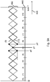
- Fig. 2 illustrates the relationship between an image 200 and a volume 300, with such type of volume being used for accumulating weights and weighted depth values during a splatting operation and holding depth value of pixels of the image 200 for an interpolation operation.
- the volume 300 is shown to have three dimensions.
- the X dimension 310 may correspond to the horizontal axis 210 of the image 200.
- the Y dimension 320 may correspond to the vertical axis 220 of the image 200.
- the I dimension 330 may correspond to the range dimension of the image, e.g., of an image component of the image 200 such as but not limited to a luminance component.
- the volume 300 may have a size which is sub-sampled with respect to the spatial dimensions and the range dimensions of the image 200.
- the volume 300 may have dimensions of 18x12x18 (X, Y, I), that is 18x12 (X, Y) for the spatial dimensions 310, 320 and 18 (I) for the range dimension 330.
- the cells of the volume 300 may represent bins. During a splatting operation, such bins may define accumulation intervals for the accumulation of depth information of the image 200.
- the bins used in the accumulation of a weight or weighted depth value associated with a particular pixel are selected as a function of the spatial coordinate of the pixel and its range value.
- the luminance values of the image 200 may determine the coordinate of the bin along the I dimension 330 of the volume 300, in that the depth information of dark image content may be accumulated in 'lower' bins of the volume 300, as illustrated by the arrow 260, whereas the depth information of bright image content may be accumulated in 'higher' bins of the volume 300, as illustrated by the arrow 250.
- the spatial location of the image content may define the location of the bin along the spatial dimensions 310, 320 of the volume 300. Accordingly, the combination of spatial coordinate and range value of a pixel of the image 200, i.e., the coordinate of the pixel in the (at least) 3D coordinate system of the image, may determine in which bin(s) of the volume 300 a weight or a weighted depth value is accumulated during a splatting operation, or which bin(s) hold the depth value of a pixel for interpolation by an interpolation operation.
- This determining of bins may essentially involve mapping the pixel's spatial coordinate and range value to a coordinate in the volume's coordinate space and on the basis of its relative position in the volume identifying bins to be used during the splatting and interpolation.
- adjacent bins may be identified to determine to which bins the pixel contributes on the basis of its splatting footprint (with the 'contribution' being the accumulation of the weight or weighted depth value), while during interpolation, adjacent bins may be identified to determine between which bins the interpolation is to be performed on the basis of the pixel's relative position within a volume.
- a mapping function may be used which maps the pixel's spatial coordinate and range value to a coordinate in the volume's coordinate space, with the latter coordinate then being directly indicative of the adjacent bins.
- multiple pixels of the image 200 may contribute to a single bin of the volume 300, in that their depth values may, at least in part, be accumulated in the single bin.
- a single pixel may contribute to several bins of the volume 300 as its coordinates in the volume's coordinate system may lie in between several cells of the volume 300.
- the depth value may have to be weighted to account for the contribution to several cells of the volume 300. This is also referred to as 'splatting'.
- Fig. 3A illustrates such a splatting operation along a single dimension K 400.
- This dimension K may be the horizontal (X), the vertical (Y), or the luminance (I) dimension.
- the dimension K 400 is considered to represent the luminance dimension I.
- this dimension is divided into bins 440, e.g., by sub-sampling of the luminance dimension I, e.g., from 256 values ( 8 bit, 0 to 255 ) down to sixteen bins of width 16.
- each bin is a storage element that may hold a particular value or a sum of accumulated values. It is noted that for illustration purposes, and in particular to improve the visibility of the Figures, in Fig.
- a conventional histogram may be obtained as follows: for each pixel of an image, it may be determined within which single bin its luminance value falls. Then, the value of that bin may be incremented, e.g., by 1. As a result, the relative position of the luminance value with respect to the luminance interval associated with the bin may be irrelevant.
- a bin defines a luminance interval of [0...7] for accumulation
- all luminance values which fall within this bin may cause a same increment, namely by 1, irrespective of whether the luminance value falls within a center of the bin (e.g., luminance values 3 and 4) or at an edge of the bin (e.g., luminance values 0 and 7).
- Splatting techniques may be used to obtain a better, e.g., more accurate histogram representation. Namely, the relative position of a luminance value within a bin may be taken into account by weighting. In such splatting techniques, the contribution of the pixel being 'splat' may be determined by explicitly or implicitly assigning a footprint to the coordinate of the pixel along the luminance dimension, e.g., to the luminance value. An accumulation by splatting may be performed as follows: for a luminance value of a pixel, it is determined to which adjacent bins the pixel contributes, with 'contributing' referring to a bin falling at least in part within the footprint of the pixel.
- the values in the adjacent bins may then be incremented by respective weights which depend on the relative position of the luminance value with respect to the two bins. For example, when the luminance value falls centrally within a 'present' bin, the contribution to that bin may be 'high' whereas the contribution to the 'previous' (lower) bin and to the 'next' (higher) bin may be low. Similarly, when a luminance value falls in between two bins, the contribution to each bin may be half of the 'high' value.
- the aforementioned position-dependent weighting may embody such a footprint-based contribution to bins. It is noted that since the weighting only defines a contribution to a bin within a particular interval, this interval may also be considered to represent the 'accumulation interval' of the particular bin. For example, the accumulation interval of the 'present' (or 'current') bin may be considered to include the present bin while also extending halfway into the previous bin and the next bin. Thus, starting halfway in the previous bin, the contribution to the present bin may slowly increase from zero to a maximum centrally within the present bin and then slowly decrease to zero halfway in the next bin.
- the accumulated values in the bins may represent a more accurate representation of a histogram.
- the footprint is considered to contribute at the most to two adjacent bins, e.g., by having a size with corresponds to the size of a bin or being smaller.
- a pixel contributes at the most to a bin [n] and a bin [n+1], with n being a bin index or coordinate in the coordinate system of the volume.
- the first bin may in the following be referred to as the 'present' bin and the second bin may be referred to as the 'next' bin.
- a particularly specific and efficient implementation defines the accumulation intervals of the bins such that the contribution of a pixel within the present bin is only to the present bin and the next bin.
- This implementation may be considered to have an 'offset' of half a bin to where one would intuitively understand the contribution of a pixel to lie. Namely, in this specific implementation, a maximum contribution to a bin is not obtained in the middle of the bin but at its lowest boundary.
- a reason for defining the bins in this manner is to allow more hardware re-use between the splatting operation and the interpolation operation, e.g., when considering the calculation and storing of weights and/or the calculation of relative positions with respect to a bin.
- a luminance value p0 which is a luminance value at the left side of bin [5].
- This relative position may contribute a 'high' weight to bin [5] according to the weighting function 430 (dotted line being at/near maximum) and a 'low' weight to bin [6] (dashed line being at/near zero).
- a luminance value p1 which is in the middle of bin [5].
- This relative position may contribute an equal weight (half of the 'high' weight) to bins [5] and [6].
- a luminance value p2 at the right side of bin [5].
- This relative position may contribute a 'low' weight to bin [5] and a 'high' weight to bin [6]. Accordingly, the relative position of the luminance value may determine the weight by which the luminance value is accumulated in the present and next bin.
- the example of Fig. 3A thereby illustrates a linear 'fade-over' from a maximum contribution to bin [5] to a maximum contribution to bin [6] depending on the luminance value.
- the accumulation interval associated with bin [5] may be the interval spanning bin [5] and its previous bin, e.g., the interval corresponding to the dotted line covering bins [4] and [5] in Fig. 3A .
- the accumulation interval associated with bin [6] may be the interval spanning bin [6] and its previous bin, e.g., the interval corresponding to the dashed line covering bins [5] and [6] in Fig. 3A .
- Fig. 3B shows more details of a similar embodiment, but applied to the accumulation of weighted depth values and weights in respective volumes, namely the aforementioned sum-of-weighted depth volume and the sum-of-weights volume.
- both volumes have a fixed maximum size of 18x12x18 bins (X, Y, I) irrespective of the image's size, while the actual number of bins which are may vary.
- a "sizeBinK" parameter may be used in the splatting operation to define the size of a non-edge bin 444 and thus determine how many bins are used. This size which may be a power of 2 to reduce the complexity of the implementation.
- the size of the two bins at the edge of a dimension "edgeBinK" may vary to allow any value of the dimension size.
- Fig. 3B shows a lower edge bin 442.
- edge bins allow the non-edge bins to have a size equal to a power-of-2, thereby simplifying the implementation complexity. Namely, normalization in fixed point arithmetic may be performed by a simple shift operation. In addition, using two edge bins (at the upper and lower end) has shown to yield better filter results as the edge bins coincide with the edges of the image.
- edge bins of a certain size may be desirable, while having at the minimum 1 ⁇ 4 of the regular bin size and at the maximum 3 ⁇ 4 of the regular bin size.
- Fig. 3B further shows an example of the bin addressing and associated weights for both the splatting and the depth interpolation.
- Fig. 3B shows a single dimension only. This dimension can be either the X, Y of the image position, or the range dimension.
- Fig. 3B shows the position 410 of depth samples at the indicated index positions [0] ... [12], e.g., corresponding to the positions of samples along a line in the input depth map, e.g. as obtained from the template depth data 024 of Fig. 1 .
- a corresponding splat accumulation interval 420 For each index position, a corresponding splat accumulation interval 420, a weight determined by a weight function 430 for the splatting and the depth profile interpolation (indicated by reference numeral 170 in Fig. 1 ), and a bin interval 440 are shown.
- Fig. 3B is to be interpreted as follows.
- an accumulation interval is defined which is denoted by the same numeral [7], as well as a corresponding weight function 430 which is shown in the same line-style as the accumulation interval [7].
- the weight function 430 represents a weight "f" which linearly transitions from 0 from the edges of the accumulation interval [7] to 1 at the center of the accumulation interval [7].
- a weight "1-f" is shown which, in the left-half of the accumulation interval [7], represents a weight for the depth sample [6] in its halfway-overlapping accumulation interval [6], and on the right-half of the accumulation interval [7], represents a weight for the depth sample [8] in its halfway-overlapping accumulation interval [8].
- the position p determines the bin x, being [6] in this example, and the depth value d p is obtained by depth profile interpolation ('170' in Fig.
- weights 'f' and '(1-f)' may be computed as fixed-point values with normalized expressions. For example, in case of 3 bits after the binary dot, the value of 8 represents '1' and thus 'f' is in range [0..8].
- the division by 8 is a normalization step. This example is also shown in the table of Fig. 5 on Y position 10. In this and other Figures and throughout the text, 'wny' and 'wpy' represent the fixed-point values of 'f' and '(1-f)' before this normalization.
- the maximum weight may correspond to the size of the bins, e.g., 8 for a bin-size of 8. Accordingly, each step in luminance value results in a step in weight for each of the two adjacent bins. Similarly, each step in (x or y) position results in a step in weight for each of the two respective adjacent bins.
- Fig. 4 illustrates the splatting operation filling the sum-of-weighted-depths (SWD) and the sum-of-weights (SW) along a single dimension.
- the vertical Y axis is chosen, with the size of bins being 8 ("sizeBinY") and the first bin having a size of 4 (“edgeBinY”).
- the "Yposition” is simply the line number.
- the table in Fig. 4 shows the interpolation with respect to the lines in the binY with index 1.
- the "factorY” is the relative position of a line within a bin.
- weights "wpy” and “wny” are derived, which relate to the complementary weights "f" and "1-f” as described for Fig. 3B but now expressed as a weight “wny” for the 'next' bin and a weight “wpy” for the 'present' bin, with 'next' and 'present' referring to two consecutive and spatially adjacent bins.
- Splatting is essentially a down-sampling function by which a high resolution input is transformed into a low resolution output. In this example, all lines within the binY number 1 have an input depth value "20". Depending on the line position, the weight gradually shifts from bin 1 to bin 2.
- the splatting operation may involve, for each pixel in the image, determining a coordinate of the pixel in the coordinate system of the image, e.g., in the form of a (X,Y, I) coordinate, a (X,Y, R, G, B) coordinate or a (X, Y, I, U, V) coordinate.
- (I, U, V) refers to the components of a YUV signal, with the Y (luminance) component being referred to as I (Intensity) to distinguish from the Y spatial dimension. It may then be determined which adjacent cells in the sum-of-weights volume represent accumulation intervals associated with the pixel.
- a depth value of the pixel may be obtained from the depth map, possibly using interpolation if the depth map has a lower spatial resolution than the image.
- a weight may be obtained for weighting the depth value.
- the weight may be (pre)calculated based on a relative position of the pixel with respect to the accumulation interval of a respective cell as indicated by the coordinate.
- the depth value may then be weighted by the weight and accumulated in the respective cell of the sum-of-weighted-depths volume, with the weight itself being accumulated in a corresponding cell of the sum-of-weights volume.
- a linear interpolation requires 2 values.
- a bi-linear interpolation requires 4 values.
- a tri-linear interpolation uses 8 values.
- the weights may be pre-calculated values as a function of the relative position of a sample within a bin.
- the depth map may be interpolated before the splatting operation to the image resolution using the same weights as used in the splatting operation. This is illustrated in Fig. 1 by the weighting block 150 providing weight data 054 to the 2D interpolation block 170 which interpolates the depth template to image resolution.
- a slicing operation may be performed to obtain an image-adapted depth volume.
- This slicing operation may be performed by a microprocessor configured by software, which is not shown explicitly in Fig. 1 but which may have access to the memory, e.g., via DMA communication.
- the slicing operation may comprise, for each cell of the sum-of-weighted-depths volume and corresponding cell of the sum-of-weights volume, dividing the accumulated weighted depth values by the accumulated weights. As a result of this division, each bin now contains an image-adapted depth value, with the overall volume thus representing an image-adapted depth volume.
- an interpolation operation may be performed to obtain an image-adapted depth value of the image-adapted depth map for each pixel in the image.
- This interpolation operation may comprise identifying adjacent cells in the image-adapted depth volume on the basis of said cells representing accumulation intervals for the pixel in the sum-of-weighted-depths volume on the basis of the coordinate of the pixel, and applying an interpolation filter to the adjacent cells of the image-adapted depth volume, wherein the interpolation filter comprises, for each of the cells, a weight which is determined based on the relative position of the pixel with respect to the accumulation interval of a respective cell as indicated by the coordinate.
- the position of a pixel may determine the bins to be used in the interpolation, whereas the relative position of a pixel in a bin may determine the interpolation weights.
- the weights may be pre-calculated.
- the weights may be the same weights as also used in the splatting operation, and/or a same hardware circuit may be used to store or calculate the weights.
- Fig. 5 illustrates the interpolation operation in a similar manner as Fig. 4 did for the splatting operation.
- the weights are used to interpolate an output depth value from the image-adapted depth volume.
- the same weights are used for a particular relative position within a bin. This is illustrated in Fig. 1 by the weighting block 150 providing the same weight and volume index data 052 to the interpolation block 160 as to the splatting block 140.
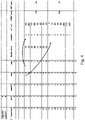
- Fig. 6 graphically shows the two weights used in Figs. 4 and 5 , namely the value of "wpy” and “wpy” on the vertical axis, as a function of the line number Y on the horizontal axis.
- the weight “wpy” is applied on the “present” value
- weight “wny” is applied on the “next” value.
- Fig. 7 corresponds to Fig. 6 but additionally shows the interpolated output as obtained between the input depth values 24 and 8 as shown in Fig. 5 - it can be seen that the weights are calculated so as to provide a linear fading between the input depth values.
- higher-order interpolation functions may be used, e.g., cubic or spline interpolations.
- the size of bins in the X or Y dimension of the described volumes may always a power of 2, since in this case the interpolation, being for example a fixed-point tri-linear interpolation, may use a shift operation for normalization, which results in a substantial reduction of hardware cost. This may result in a variable number of bins which are needed depending on the image size. With changing bin size, the filter performance may be influenced. However, experiments show that this does not significantly impacted the visual performance. Moreover, using a variable number of bins instead of a fixed number of bins does not significantly affect the hardware design.
- the size of a bin in either X or Y dimension may specified by a hardware parameter, while the analysis of which value to select may be left to, e.g., software of a microprocessor.
- processing subsystem may be provided separately of the described integrated circuit, e.g., in another type of SoC.
- Data may be provided on a computer readable medium which defines the processing subsystem in the form of netlists and/or synthesizable RTL.
- the computer readable medium, and thereby the data stored thereon, may be transitory or non-transitory.
- the processing subsystem may be provided as a synthesizable core, e.g., in a hardware description language such as Verilog or VHDL, or as generic gate-level netlists providing a boolean-algebra representation of the RTC IP block's logical function implemented as generic gates or process specific standard cells.
- the term 'map' refers to data arranged in rows and columns.
- the adjective 'depth' is to be understood as being indicative of the depth of portions of an image to the camera. Therefore, the depth map may be constituted by depth values, but also by, e.g., disparity values or parallactic shift values. Essentially, the depth map may therefore constitute a disparity map or a parallactic shift map.
- disparity refers to a difference in position of an object when perceived with a left eye or a right eye of the user.
- parallactic shift refers to a displacement of the object between two views so as to provide said disparity to the user. Disparity and parallactic shift are generally negatively correlated with distance or depth. Device and methods for conversion between all of the above types of maps and/or values are known.
- Fig. 8 shows a computer-implemented method 500 for estimating a depth map from an image.
- the method 500 is shown to comprise, in an operation titled "ACCESSING IMAGE DATA", accessing 510 image data of the image, in an operation titled “ACCESSING DEPTH DATA”, accessing 520 depth data of a template depth map, in an operation titled “APPLYING JOINT BILATERAL FILTER", applying 530 a joint bilateral filter to the template depth map using the image data as a range term in the joint bilateral filter, thereby obtaining an image-adapted depth map as output, wherein the applying the joint bilateral filter comprises, in an operation titled “INITIALIZING VOLUMES", initializing 540 a sum-of-weighted-depths volume and a sum-of-weights volume as respective data empty structures in a memory, in an operation titled “SPLATTING OPERATION”, performing 550 a splatting operation to fill said volumes, in an operation titled “SLICING OPERATION”,
- the method 500 may be implemented on a processor system, e.g., on a computer as a computer implemented method, as dedicated hardware, or as a combination of both.
- instructions for the computer e.g., executable code
- the executable code may be stored in a transitory or non-transitory manner. Examples of computer readable mediums include memory devices, optical storage devices, integrated circuits, servers, online software, etc.
- Fig. 9 shows an optical disc 600.
- any reference signs placed between parentheses shall not be construed as limiting the claim.
- Use of the verb "comprise” and its conjugations does not exclude the presence of elements or steps other than those stated in a claim.
- the invention may be implemented by means of hardware comprising several distinct elements, and by means of a suitably programmed computer. In the device claim enumerating several means, several of these means may be embodied by one and the same item of hardware.
Landscapes
- Engineering & Computer Science (AREA)
- Multimedia (AREA)
- Signal Processing (AREA)
- Physics & Mathematics (AREA)
- General Physics & Mathematics (AREA)
- Theoretical Computer Science (AREA)
- Computer Vision & Pattern Recognition (AREA)
- Image Processing (AREA)
- Image Analysis (AREA)
Description
- The invention relates to an integrated circuit configured to estimate a depth map from an image using a joint bilateral filter. The invention further relates to a method for estimating a depth map from an image using a joint bilateral filter, and to a computer readable medium comprising transitory or non-transitory data representing instructions arranged to cause a processor system to perform the method.
- Display devices such as televisions, tablets and smartphones may comprise a 3D display to provide a user with a perception of depth when viewing content on such a device. For that purpose, such 3D displays may, either by themselves or together with glasses worn by the user, provide the user with different images in each eye so as to provide the user a perception of depth based on stereoscopy.
- 3D displays typically require content which contains depth information. The depth information may be provided implicitly in the 3D content. For example, in the case of stereoscopic content, in short also referred to 'stereo' content, the depth information is provided by the differences between a left image and a right image. The depth information may also be provided explicitly in the 3D content. For example, in 3D content encoded in the so-termed image+depth format, the depth information is provided by a depth map which may comprise depth values, disparity values and/or parallactic shift values, with each of said values being indicative of the distance that objects in the image have towards the camera.
- A great amount of content that is currently available, e.g., movies, television programs, images, etc., is 2D content. Such content needs to be converted to 3D in order to enable its 3D rendering on a 3D display. Conversion to 3D may comprise generating a depth map for a 2D image, e.g., for each 2D image of a 2D video. In general, this process is referred to as '2D to 3D conversion', and may involve creating the depth map manually. For example, a software tool running on a workstation may offer a professional user the possibility to add depth to 2D images by drawing depth maps using a digital pen. The depth map may also be generated automatically. For example, a device may estimate the distance that objects within the 2D image have towards the camera and, based thereon, generate a depth map for the 2D image.
- An example of the automatic generation of a depth map is known from
US 8,447,141 , which describes a method of generating a depth map for an image using monocular information. The method comprises generating a first depth map for the image which provides a global depth profile, and which may be a simple generic template such as a slant. Moreover, a second depth map is generated which is based on the depth values of the first depth map and color and/or luminance values of the image. The generating of the second depth map may involve applying a joint bilateral filter to the first depth map using range information from the image. It is said that as a result, objects will be made more distinct from the global depth profile. - Effectively,
US 8,447,141 uses the joint bilateral filter to adapt the generic template provided by the depth map to the actual content of the image. - However, the implementation of a joint bilateral filter is computationally complex. The publication "A fast approximation of the bilateral filter using a signal processing approach" by Paris et al., International Journal of Computer Vision 81.1, 2009, pp. 24-52, describes an approximation of the joint bilateral filter which is said to be less computationally complex. Disadvantageously, the described approximation of the bilateral filter is still relatively computationally complex, and thus not well suited for cost-efficient implementation in consumer devices, e.g., in an integrated circuit.
- One of the objects of the invention is to obtain an integrated circuit configured to estimate a depth map from an image using a joint bilateral filter, which is less computationally complex than the approximation described by Paris et al.
- A first aspect of the invention provides an integrated circuit configured to estimate a depth map from an image, wherein the integrated circuit is defined by
claim 1. A further aspect of the invention provides a computer-implemented method for estimate a depth map from an image, wherein the method is defined byclaim 14. - Essentially, the integrated circuit implements the joint bilateral filter at a coarser resolution, but in a different manner than Paris et al. One of the advantageous differences is that Paris et al. first perform an interpolation and then a slicing operation, with the latter involving division. The division in Paris et al. is thus performed on data having been interpolated back to full-resolution. The integrated circuit as claimed performs a slicing operation on the down-sampled volumes, so at a greatly reduced resolution. For example, if volumes of, e.g., 18x12x18 (height × width × range) are used, only 3,888 division operations are needed, which are far fewer than would be needed to perform a division on, e.g., a 480 × 270 image (129.600 division operations). It has been found that the quality reduction of performing the slicing operation on the down-sampled volumes is very limited. However, since division operations are computationally complex to implement, the computational burden of performing the joint bilateral filter is greatly reduced. This allows the splicing operation to be performed in software, which further yields flexibility with respect to its implementation.
- It is noted that the depth map which is used as input may be a template depth map, and thereby correspond to a predetermined generic depth profile such as a slant, or a generic depth profile which is selected from a list of different generic depth profiles as best matching the content of the image. However, in general, the depth map may be any depth map which benefits from being further adapted to the image.
- It is further noted that the volumes may be three-dimensional volumes, e.g., being constituted by down-sampled versions of the two-spatial dimensions of the image and a down-sampled version of the range dimension of one of the components of the image, e.g., the luminance component. Alternatively, the volumes may comprise two or more range dimensions, which may correspond to two or more of the components of the image, e.g., the luminance and one or more chrominance components of a YUV image, or the individual color components of a RGB image, etc.
- Optionally, the processing subsystem comprises an application-specific hardware circuit and a microprocessor configurable by software, wherein:
- the application-specific hardware circuit is configured to perform the splatting operation and the interpolation operation; and
- the microprocessor is configured by the software to, during operation of the integrated circuit, perform the slicing operation.
- This aspect of the invention is based on the insight that while the splatting operation and the interpolation operation are both still relatively computationally complex, the slicing operation has been significantly reduced in complexity compared to Paris et al. by solely operating on the down-sampled volumes. As such, the slicing operation may be performed in software, yielding flexibility, whereas the splatting operation and the interpolation operation may be performed in hardware in view of the generally higher efficiency of a hardware implementation versus software.
- Optionally, the application-specific hardware circuit comprises a filter table for storing the splatting weights used in the splatting operation and/or the interpolation weights used in the interpolation operation. In case the splatting operation and the interpolation operation are hardware operations, said weights may be stored in a filter table of the hardware circuit, which may be a read-only memory or a random-access memory. This enables said weights to be readily accessible by the hardware of the respective operations.
- Optionally, the filter table is loaded with the splatting weights used in the splatting operation and the interpolation weights used in the interpolation operation before performing the respective operation. In case different weights are used for the splatting operation than for the interpolation operation, these weights may be loaded into the filter table before the respective operation is performed, e.g., by the microprocessor. In this way, the hardware of the filter table is re-used and not separately implemented for both the hardware of the splatting operation and the hardware of the interpolation operation. It is noted that in addition or alternatively to the re-use of the hardware of the filter table between the splatting and the interpolation operation, in general there may also be re-use of hardware for determining the relative position of a sample within a bin between the splatting and the interpolation operation.
- Optionally, the splatting weights used in the splatting operation and the interpolation weights used in the interpolation operation are the same. This aspect of the invention is based on the insight that the same weights may be used for performing the splatting operation as for performing the interpolation operation since both are essentially similar operations which in the present context also operate on, on the one hand, the image, and on the other hand, a multi-dimensional volume having down-sampled dimensions with respect to the two spatial dimensions and the range dimension of the image. By using the same weights, the implementation of both operations is considerably more efficient.
- Optionally, the splatting weights used in the splatting operation and the interpolation weights used in the interpolation operation represent a linear interpolation with respect to the coordinate system of the image. The weights are thus chosen so that a linear interpolation is applied to the data in the respective volumes of the splatting operation and the interpolation operation along each of the dimensions of the volumes. For example, for a three-dimensional volume, a tri-linear interpolation may be used, while for a quad-dimensional volume, e.g., having two range dimensions, a quad-linear interpolation may be used. Linear interpolation has been found to be well-suited for the spatting operation and the interpolation operation. Alternatively, a higher-order interpolation may be used in each dimension, including but not limited to a cubic interpolation.
- Optionally, the microprocessor is configured by the software to, during operation of the integrated circuit, apply a temporal filtering to the sum-of-weighted-depths volume and to the sum-of-weights volume before performing the slicing operation. Temporal filtering is often applied to depth maps to ensure temporal stability. Instead or additionally to applying such temporal filtering to the depth map, the volumes which are used for generating the depth map themselves may be temporally filtered. This has been found to yield a more temporally stable depth map, while being computationally efficient to implement to the relatively small size of the volumes compared to an image. For example, a typical volume of 18x12x18 contains 3,888 data values to be filtered, whereas an image of 480x270 contains 129,600 data values to be filtered. Due to the filtering being specifically applied to the volume(s), a software implementation is possible. Advantageously, it has been found that applying an Infinite Impulse Response (IIR) filter to the sum-of-weighted-depths volume improves the temporal stability of the resulting depth map in case of so-termed shot-cuts, without a need for dedicated shot-cut processing, e.g., involving dedicated shot-cut detectors. The temporal filtering may, for example, be a first- or higher-order infinite impulse response filter, and may be implemented as part of other (non-linear) operations on the volume data.
- Optionally, the microprocessor is configured by the software to, during operation of the integrated circuit, apply a temporal filtering to the image-adapted depth volume. Such temporal filtering offers comparable reductions in computational complexity compared to the filtering of an actual image as described with respect to the filtering of the sum-of-weighted-depths volume or the sum-of-weights volume. The temporal filtering may be of a same type as described with respect to the filtering of the sum-of-weighted-depths volume or the sum-of-weights volume.
- Optionally, the processing subsystem is configured to, after performing the splatting operation, convolute the sum-of-weighted-depths volume with a Gaussian kernel. It has been found that such a convolution improves the quality of the depth map.
- Optionally, the template depth map has a reduced spatial resolution with respect to the image, e.g., having two spatial dimensions corresponding to the two spatial dimensions of the sum-of-weighted-depths volume and the sum-of-weights volume. The template depth map may then be interpolated using the same weights as used in the splatting operation.
- Optionally, the joint bilateral filter is applied to only to luminance data of the image. Optionally, the joint bilateral filter is applied to the luminance data and chrominance data of the image. In the latter case, the volumes may be five-dimensional volumes having three range dimensions, e.g., a Y, U and V dimension.
- Optionally, the integrated circuit is, or is part of, a field-programmable gate array or a system on chip. The integrated circuit may be part of a device such as a display device or set-top box, but also other devices in which it may be used to convert 2D video to 3D video by estimating the depth map.
- A further aspect of the invention provides a computer readable medium comprising transitory or non-transitory data representing instructions arranged to cause a processor system to perform the method.
- It will be appreciated by those skilled in the art that two or more of the above-mentioned embodiments, implementations, and/or aspects of the invention may be combined in any way deemed useful.
- Modifications and variations of the method which correspond to the described modifications and variations of the integrated circuit can be carried out by a person skilled in the art on the basis of the present description.
- These and other aspects of the invention are apparent from and will be elucidated with reference to the embodiments described hereinafter. In the drawings,
-
Fig. 1 schematically shows an integrated circuit which is configured to estimate a depth map from an image in a computationally efficient manner; -
Fig. 2 illustrates the relationship between an image and a volume which may be used to accumulate weights and weighted depth values during a splatting operation and which may hold depth values for an interpolation operation; -
Fig. 3A shows a simplified example of a splatting operation; -
Fig. 3B shows a detailed example illustrating bin addressing and associated weights for both the splatting operation and the interpolation operation; -
Fig. 4 illustrates various aspects of the splatting operation; -
Figs. 5 to 7 illustrates various aspects of the interpolation operation -
Fig. 8 shows a method for estimating a depth map from an image; and -
Fig. 9 shows a computer-readable medium comprising instructions for causing a processor system to perform the method. - It should be noted that items which have the same reference numbers in different Figures, have the same structural features and the same functions, or are the same signals. Where the function and/or structure of such an item has been explained, there is no necessity for repeated explanation thereof in the detailed description.
- The following list of references and abbreviations is provided for facilitating the interpretation of the drawings and shall not be construed as limiting the claims.
- 010
- image data
- 020
- depth volume input data
- 022
- depth output data
- 024
- template depth data
- 026
- interpolated template depth data
- 030
- sum of weights volume data
- 032
- sum of weighted depth volume data
- 052
- weight and volume index data
- 054
- weight data
- 100
- processing subsystem of integrated circuit
- 110
- image data input interface
- 120
- depth volume data input interface
- 122
- depth data output interface
- 130-132
- volume data output interface
- 140
- splatting block
- 150
- weighting block
- 160
- interpolation block
- 170
- 2D interpolation block
- 180
- control logic
- 200
- image
- 210
- horizontal dimension
- 220
- vertical dimension
- 250
- mapping of bright image patch
- 260
- mapping of dark image background
- 300
- volume representation of image
- 310
- horizontal dimension
- 320
- vertical dimension
- 330
- range dimension
- 400
- dimension (horizontal, vertical or range)
- 410
- series of depth samples
- 420
- splat accumulation interval
- 430
- weight function
- 440
- bin interval
- 442
- edge bin
- 444
- non-edge bin
- 500
- method for estimating depth map from image
- 510
- accessing image data
- 520
- accessing depth data
- 530
- applying joint bilateral filter
- 540
- initializing volumes
- 550
- splatting operation
- 560
- slicing operation
- 570
- interpolation operation
- 600
- computer readable medium
- 610
- non-transitory data representing instructions
-
Fig. 1 schematically shows aprocessing subsystem 100 of an integrated circuit which is configured to estimate a depth map from an image in a computationally efficient manner. Theprocessing subsystem 100 is shown as a functional block diagram, and may be embodied by components such as a microprocessor, an application-specific hardware circuit and one or more local memories. The integrated circuit may comprise other components which are not shown inFig. 1 , including but not limited to other microprocessors, a bus system, other memories, etc. In general, the integrated circuit may be implemented as, or as part of, a field-programmable gate array (FPGA) or a System-on-Chip (SoC) or in any other suitable manner. - The
processing subsystem 100 is shown to comprise an imagedata input interface 110 via whichimage data 010 may be read from a memory, e.g., via Direct Memory Access (DMA) communication. For example, the image data may be luminance input data Yin. In this respect, it is noted that the imagedata input interface 110 and other interfaces of theprocessing subsystem 100 may comprise or be connected to a local memory acting as buffer, labeled 'Buf' throughoutFig. 1 . - The
processing subsystem 100 is further shown to comprise a depth volumedata input interface 120 via whichdepth volume data 020 may be read from the memory, and a depthdata output interface 122 via whichdepth data 022 may be written to the memory. Theprocessing subsystem 100 is further shown to comprise respective volumedata output interfaces weights volume data 030 and sum of weighteddepth volume data 032 to the memory. - Other functional blocks of the
processing subsystem 100 include asplatting block 140 which communicates with the volumedata output interfaces interpolation block 160 which communicates with the depth data interfaces 120, 122, aweighting block 150 which communicates with the imagedata input interface 110 and provides weight andvolume index data 052 to thesplatting block 140 and theinterpolation block 160, a2D interpolation block 170 which receivestemplate depth data 024 fromcontrol logic 180 and weight data 054 from theweighting block 150 and provides interpolatedtemplate depth data 026 to thesplatting block 140. - In an embodiment, the
processing subsystem 100 as shown inFig. 1 may be implemented as an application-specific hardware circuit. In addition, a separate microprocessor (not shown inFig. 1 ) may be provided in the integrated circuit which is configured to perform a slicing operation, as also discussed onwards. For that purpose, the microprocessor may have access to the memory, e.g. via DMA. Alternatively, the slicing operation may also be implemented by the application-specific hardware circuit. - The operation of the
processing subsystem 100 and its functional blocks will be further explained with reference toFigs. 2-7 . In this respect, it is noted that inFig. 1 the "*" denotes a local buffer or an interface that is associated with a volumetric multi-dimensional data representation, as explained with reference toFig. 2 . -
Fig. 2 illustrates the relationship between animage 200 and avolume 300, with such type of volume being used for accumulating weights and weighted depth values during a splatting operation and holding depth value of pixels of theimage 200 for an interpolation operation. Thevolume 300 is shown to have three dimensions. TheX dimension 310 may correspond to thehorizontal axis 210 of theimage 200. TheY dimension 320 may correspond to thevertical axis 220 of theimage 200. TheI dimension 330 may correspond to the range dimension of the image, e.g., of an image component of theimage 200 such as but not limited to a luminance component. Thevolume 300 may have a size which is sub-sampled with respect to the spatial dimensions and the range dimensions of theimage 200. For example, while theimage 200 may have spatial dimensions of 480 pixels by 270 lines (X, Y) and a 8-bit range dimension (I) defining a range of 256 values, thevolume 300 may have dimensions of 18x12x18 (X, Y, I), that is 18x12 (X, Y) for thespatial dimensions range dimension 330. - The cells of the
volume 300 may represent bins. During a splatting operation, such bins may define accumulation intervals for the accumulation of depth information of theimage 200. Here, the bins used in the accumulation of a weight or weighted depth value associated with a particular pixel are selected as a function of the spatial coordinate of the pixel and its range value. For example, the luminance values of theimage 200 may determine the coordinate of the bin along theI dimension 330 of thevolume 300, in that the depth information of dark image content may be accumulated in 'lower' bins of thevolume 300, as illustrated by thearrow 260, whereas the depth information of bright image content may be accumulated in 'higher' bins of thevolume 300, as illustrated by thearrow 250. In addition, the spatial location of the image content may define the location of the bin along thespatial dimensions volume 300. Accordingly, the combination of spatial coordinate and range value of a pixel of theimage 200, i.e., the coordinate of the pixel in the (at least) 3D coordinate system of the image, may determine in which bin(s) of the volume 300 a weight or a weighted depth value is accumulated during a splatting operation, or which bin(s) hold the depth value of a pixel for interpolation by an interpolation operation. - This determining of bins may essentially involve mapping the pixel's spatial coordinate and range value to a coordinate in the volume's coordinate space and on the basis of its relative position in the volume identifying bins to be used during the splatting and interpolation. Effectively, during splatting, adjacent bins may be identified to determine to which bins the pixel contributes on the basis of its splatting footprint (with the 'contribution' being the accumulation of the weight or weighted depth value), while during interpolation, adjacent bins may be identified to determine between which bins the interpolation is to be performed on the basis of the pixel's relative position within a volume. For that purpose, a mapping function may be used which maps the pixel's spatial coordinate and range value to a coordinate in the volume's coordinate space, with the latter coordinate then being directly indicative of the adjacent bins.
- Due to the sub-sampling, multiple pixels of the
image 200 may contribute to a single bin of thevolume 300, in that their depth values may, at least in part, be accumulated in the single bin. Conversely, a single pixel may contribute to several bins of thevolume 300 as its coordinates in the volume's coordinate system may lie in between several cells of thevolume 300. As such, when accumulating the pixel's depth value in thevolume 300, the depth value may have to be weighted to account for the contribution to several cells of thevolume 300. This is also referred to as 'splatting'. -
Fig. 3A illustrates such a splatting operation along a single dimension K 400. This dimension K may be the horizontal (X), the vertical (Y), or the luminance (I) dimension. For this explanation, the dimension K 400 is considered to represent the luminance dimension I. First, this dimension is divided intobins 440, e.g., by sub-sampling of the luminance dimension I, e.g., from 256 values (8 bit, 0 to 255) down to sixteen bins ofwidth 16. As is known per se, each bin is a storage element that may hold a particular value or a sum of accumulated values. It is noted that for illustration purposes, and in particular to improve the visibility of the Figures, inFig. 3A and the following, a binning is shown which only involves twelve bins in total: ten 'normal' bins [1] to [10] and two so-called 'edge bins' [0] and [11]. Note that the different size and purpose of edge bins [0] and [11] will be explained with further reference toFig. 3B . - The following illustrates the splatting operation with reference to a histogram operation. A conventional histogram may be obtained as follows: for each pixel of an image, it may be determined within which single bin its luminance value falls. Then, the value of that bin may be incremented, e.g., by 1. As a result, the relative position of the luminance value with respect to the luminance interval associated with the bin may be irrelevant. For example, if a bin defines a luminance interval of [0...7] for accumulation, all luminance values which fall within this bin may cause a same increment, namely by 1, irrespective of whether the luminance value falls within a center of the bin (e.g.,
luminance values 3 and 4) or at an edge of the bin (e.g.,luminance values 0 and 7). - Splatting techniques may be used to obtain a better, e.g., more accurate histogram representation. Namely, the relative position of a luminance value within a bin may be taken into account by weighting. In such splatting techniques, the contribution of the pixel being 'splat' may be determined by explicitly or implicitly assigning a footprint to the coordinate of the pixel along the luminance dimension, e.g., to the luminance value. An accumulation by splatting may be performed as follows: for a luminance value of a pixel, it is determined to which adjacent bins the pixel contributes, with 'contributing' referring to a bin falling at least in part within the footprint of the pixel. The values in the adjacent bins may then be incremented by respective weights which depend on the relative position of the luminance value with respect to the two bins. For example, when the luminance value falls centrally within a 'present' bin, the contribution to that bin may be 'high' whereas the contribution to the 'previous' (lower) bin and to the 'next' (higher) bin may be low. Similarly, when a luminance value falls in between two bins, the contribution to each bin may be half of the 'high' value.
- The aforementioned position-dependent weighting may embody such a footprint-based contribution to bins. It is noted that since the weighting only defines a contribution to a bin within a particular interval, this interval may also be considered to represent the 'accumulation interval' of the particular bin. For example, the accumulation interval of the 'present' (or 'current') bin may be considered to include the present bin while also extending halfway into the previous bin and the next bin. Thus, starting halfway in the previous bin, the contribution to the present bin may slowly increase from zero to a maximum centrally within the present bin and then slowly decrease to zero halfway in the next bin.
- As a result of the use of the splatting operation, the accumulated values in the bins may represent a more accurate representation of a histogram.
- In a specific and efficient implementation of the splatting operation, the footprint is considered to contribute at the most to two adjacent bins, e.g., by having a size with corresponds to the size of a bin or being smaller. In this case, a pixel contributes at the most to a bin [n] and a bin [n+1], with n being a bin index or coordinate in the coordinate system of the volume. The first bin may in the following be referred to as the 'present' bin and the second bin may be referred to as the 'next' bin.
- A particularly specific and efficient implementation defines the accumulation intervals of the bins such that the contribution of a pixel within the present bin is only to the present bin and the next bin. This implementation, however, may be considered to have an 'offset' of half a bin to where one would intuitively understand the contribution of a pixel to lie. Namely, in this specific implementation, a maximum contribution to a bin is not obtained in the middle of the bin but at its lowest boundary. A reason for defining the bins in this manner is to allow more hardware re-use between the splatting operation and the interpolation operation, e.g., when considering the calculation and storing of weights and/or the calculation of relative positions with respect to a bin.
- As an example, consider in
Fig. 3A the case of a luminance value p0, which is a luminance value at the left side of bin [5]. This relative position may contribute a 'high' weight to bin [5] according to the weighting function 430 (dotted line being at/near maximum) and a 'low' weight to bin [6] (dashed line being at/near zero). Next, consider the case of a luminance value p1, which is in the middle of bin [5]. This relative position may contribute an equal weight (half of the 'high' weight) to bins [5] and [6]. Finally, consider the case of a luminance value p2 at the right side of bin [5]. This relative position may contribute a 'low' weight to bin [5] and a 'high' weight to bin [6]. Accordingly, the relative position of the luminance value may determine the weight by which the luminance value is accumulated in the present and next bin. The example ofFig. 3A thereby illustrates a linear 'fade-over' from a maximum contribution to bin [5] to a maximum contribution to bin [6] depending on the luminance value. - It will be appreciated that in this specific and efficient implementation in which a pixel, having a luminance value within the present bin, contributes only to the present bin and the next bin, the accumulation interval associated with bin [5] may be the interval spanning bin [5] and its previous bin, e.g., the interval corresponding to the dotted line covering bins [4] and [5] in
Fig. 3A . Likewise, the accumulation interval associated with bin [6] may be the interval spanning bin [6] and its previous bin, e.g., the interval corresponding to the dashed line covering bins [5] and [6] inFig. 3A . -
Fig. 3B shows more details of a similar embodiment, but applied to the accumulation of weighted depth values and weights in respective volumes, namely the aforementioned sum-of-weighted depth volume and the sum-of-weights volume. - In this example, both volumes have a fixed maximum size of 18x12x18 bins (X, Y, I) irrespective of the image's size, while the actual number of bins which are may vary. Namely, a "sizeBinK" parameter may be used in the splatting operation to define the size of a
non-edge bin 444 and thus determine how many bins are used. This size which may be a power of 2 to reduce the complexity of the implementation. The size of the two bins at the edge of a dimension "edgeBinK" may vary to allow any value of the dimension size.Fig. 3B shows alower edge bin 442. For example, if the image width is 480 and sizeBinX is selected to be 32, there may be 14 non-edge bins and 2 edge bins each having a width of (480 - 14*32)/2 = 16. In another example, if the image height is 270 and sizeBinY is 32, the width of each of the edge bins may be (270 - 8*32)/2 = 7. As such, the use of edge bins allows the non-edge bins to have a size equal to a power-of-2, thereby simplifying the implementation complexity. Namely, normalization in fixed point arithmetic may be performed by a simple shift operation. In addition, using two edge bins (at the upper and lower end) has shown to yield better filter results as the edge bins coincide with the edges of the image. It may thus be desirable to have edge bins of a certain size on purpose. For example, it has been found that edge bins being half-size of a regular non-edge bin may be preferred, while having at the minimum ¼ of the regular bin size and at the maximum ¾ of the regular bin size. -
Fig. 3B further shows an example of the bin addressing and associated weights for both the splatting and the depth interpolation. For ease of understanding,Fig. 3B shows a single dimension only. This dimension can be either the X, Y of the image position, or the range dimension. Specifically,Fig. 3B shows theposition 410 of depth samples at the indicated index positions [0] ... [12], e.g., corresponding to the positions of samples along a line in the input depth map, e.g. as obtained from thetemplate depth data 024 ofFig. 1 . For each index position, a correspondingsplat accumulation interval 420, a weight determined by aweight function 430 for the splatting and the depth profile interpolation (indicated byreference numeral 170 inFig. 1 ), and abin interval 440 are shown.Fig. 3B is to be interpreted as follows. For a given index position, e.g., index position [7], an accumulation interval is defined which is denoted by the same numeral [7], as well as acorresponding weight function 430 which is shown in the same line-style as the accumulation interval [7]. Theweight function 430 represents a weight "f" which linearly transitions from 0 from the edges of the accumulation interval [7] to 1 at the center of the accumulation interval [7]. Within the same accumulation interval [7], also a weight "1-f" is shown which, in the left-half of the accumulation interval [7], represents a weight for the depth sample [6] in its halfway-overlapping accumulation interval [6], and on the right-half of the accumulation interval [7], represents a weight for the depth sample [8] in its halfway-overlapping accumulation interval [8]. - It can be seen that the accumulation intervals and weights are selected such that, for a given position p along the shown dimension, the bins of the sum-of-weights volume may be accumulated in accordance with SW[x] += f and SW[x+1] += (1-f) whereas the bins of the sum-of-weighted-depths volume may be accumulated in accordance with SWD[x] += f*dp and SWD[x+1] += (1-f)*dp. Here, the position p determines the bin x, being [6] in this example, and the depth value dp is obtained by depth profile interpolation ('170' in
Fig. 1 ) from the depth map D in accordance with dp = (1-f) * D[x] + f * D[x+1]. It is noted that this is only for a single dimension; typically, the addressing of the bins is based on the spatial dimensions X, Y and one or more range dimensions I of the image, and thereby typically depends also on the image data itself. - It is noted that the weights 'f' and '(1-f)' may be computed as fixed-point values with normalized expressions. For example, in case of 3 bits after the binary dot, the value of 8 represents '1' and thus 'f' is in range [0..8]. In a specific example, if one were to assume that dp = (f-1) * D[x] + f * D[x+1] is to be computed, with D[x] being 24, D[x+1] being 8 and f being 6, 'dp' may be computed as ((8-6)*24 + 6*8) / 8 = 96 / 8 = 12. The division by 8 is a normalization step. This example is also shown in the table of
Fig. 5 onY position 10. In this and other Figures and throughout the text, 'wny' and 'wpy' represent the fixed-point values of 'f' and '(1-f)' before this normalization. - In a specific and efficient embodiment, the maximum weight may correspond to the size of the bins, e.g., 8 for a bin-size of 8. Accordingly, each step in luminance value results in a step in weight for each of the two adjacent bins. Similarly, each step in (x or y) position results in a step in weight for each of the two respective adjacent bins.
-
Fig. 4 illustrates the splatting operation filling the sum-of-weighted-depths (SWD) and the sum-of-weights (SW) along a single dimension. In this example, the vertical Y axis is chosen, with the size of bins being 8 ("sizeBinY") and the first bin having a size of 4 ("edgeBinY"). The "Yposition" is simply the line number. The table inFig. 4 shows the interpolation with respect to the lines in the binY withindex 1. The "factorY" is the relative position of a line within a bin. Based on the "factorY" value, two weights "wpy" and "wny" are derived, which relate to the complementary weights "f" and "1-f" as described forFig. 3B but now expressed as a weight "wny" for the 'next' bin and a weight "wpy" for the 'present' bin, with 'next' and 'present' referring to two consecutive and spatially adjacent bins. Splatting is essentially a down-sampling function by which a high resolution input is transformed into a low resolution output. In this example, all lines within thebinY number 1 have an input depth value "20". Depending on the line position, the weight gradually shifts frombin 1 tobin 2. As such, on line number 4 (which is the first line in bin 1), the complete value is accumulated tobin 1 and none of the value is added tobin 2, which is illustrated inFig. 4 by the two arrows. On line number 8 (halfway the bin), 50% of the value is added tobin 1 and 50% is added tobin 2. This way, a linear fade-over between the bins is achieved. Using the weights, the cells of the SW (sum-of-weights) volume only accumulates the applied weights, whereas the cells of the SWD (sum-of-weighted-depths) volume accumulate the depth value multiplied by the weight ("weighted depth"). - In summary, the splatting operation may involve, for each pixel in the image, determining a coordinate of the pixel in the coordinate system of the image, e.g., in the form of a (X,Y, I) coordinate, a (X,Y, R, G, B) coordinate or a (X, Y, I, U, V) coordinate. In the latter, (I, U, V) refers to the components of a YUV signal, with the Y (luminance) component being referred to as I (Intensity) to distinguish from the Y spatial dimension. It may then be determined which adjacent cells in the sum-of-weights volume represent accumulation intervals associated with the pixel. A depth value of the pixel may be obtained from the depth map, possibly using interpolation if the depth map has a lower spatial resolution than the image. For each of the adjacent cells, a weight may be obtained for weighting the depth value. The weight may be (pre)calculated based on a relative position of the pixel with respect to the accumulation interval of a respective cell as indicated by the coordinate. The depth value may then be weighted by the weight and accumulated in the respective cell of the sum-of-weighted-depths volume, with the weight itself being accumulated in a corresponding cell of the sum-of-weights volume.
- It is noted that for a single dimension, a linear interpolation requires 2 values. Similarly, for two dimensions, a bi-linear interpolation requires 4 values. For the volume of 3 dimensions, a tri-linear interpolation uses 8 values. The weights may be pre-calculated values as a function of the relative position of a sample within a bin. In case the depth map has a reduced spatial resolution with respect to the image, and in particular the same reduced spatial resolution as the sum-of-weighted-depths volume and the sum-of-weights volume, the depth map may be interpolated before the splatting operation to the image resolution using the same weights as used in the splatting operation. This is illustrated in
Fig. 1 by theweighting block 150 providing weight data 054 to the2D interpolation block 170 which interpolates the depth template to image resolution. - Having performed the splatting operation, a slicing operation may be performed to obtain an image-adapted depth volume. This slicing operation may be performed by a microprocessor configured by software, which is not shown explicitly in
Fig. 1 but which may have access to the memory, e.g., via DMA communication. The slicing operation may comprise, for each cell of the sum-of-weighted-depths volume and corresponding cell of the sum-of-weights volume, dividing the accumulated weighted depth values by the accumulated weights. As a result of this division, each bin now contains an image-adapted depth value, with the overall volume thus representing an image-adapted depth volume. - Having performed the slicing operation, an interpolation operation may be performed to obtain an image-adapted depth value of the image-adapted depth map for each pixel in the image. This interpolation operation may comprise identifying adjacent cells in the image-adapted depth volume on the basis of said cells representing accumulation intervals for the pixel in the sum-of-weighted-depths volume on the basis of the coordinate of the pixel, and applying an interpolation filter to the adjacent cells of the image-adapted depth volume, wherein the interpolation filter comprises, for each of the cells, a weight which is determined based on the relative position of the pixel with respect to the accumulation interval of a respective cell as indicated by the coordinate. In other words, the position of a pixel, as determined by its spatial coordinate and its range value(s), may determine the bins to be used in the interpolation, whereas the relative position of a pixel in a bin may determine the interpolation weights. The weights may be pre-calculated. In particular, the weights may be the same weights as also used in the splatting operation, and/or a same hardware circuit may be used to store or calculate the weights.
-
Fig. 5 illustrates the interpolation operation in a similar manner asFig. 4 did for the splatting operation. Here, the weights are used to interpolate an output depth value from the image-adapted depth volume. As can be seen when comparingFig. 5 withFig. 4 , the same weights are used for a particular relative position within a bin. This is illustrated inFig. 1 by theweighting block 150 providing the same weight andvolume index data 052 to theinterpolation block 160 as to thesplatting block 140. The righthand part of the table shows how the weights are applied on input depth values 24 and 8. For example, the interpolation onY position 7 yields ((5×24+3×8))/8=18. -
Fig. 6 graphically shows the two weights used inFigs. 4 and5 , namely the value of "wpy" and "wpy" on the vertical axis, as a function of the line number Y on the horizontal axis. The weight "wpy" is applied on the "present" value, whereas weight "wny" is applied on the "next" value.Fig. 7 corresponds toFig. 6 but additionally shows the interpolated output as obtained between the input depth values 24 and 8 as shown inFig. 5 - it can be seen that the weights are calculated so as to provide a linear fading between the input depth values. In addition to linear fading, also higher-order interpolation functions may be used, e.g., cubic or spline interpolations. - In general, it is noted that the size of bins in the X or Y dimension of the described volumes may always a power of 2, since in this case the interpolation, being for example a fixed-point tri-linear interpolation, may use a shift operation for normalization, which results in a substantial reduction of hardware cost. This may result in a variable number of bins which are needed depending on the image size. With changing bin size, the filter performance may be influenced. However, experiments show that this does not significantly impacted the visual performance. Moreover, using a variable number of bins instead of a fixed number of bins does not significantly affect the hardware design. The size of a bin in either X or Y dimension may specified by a hardware parameter, while the analysis of which value to select may be left to, e.g., software of a microprocessor.
- It will be appreciated that, in general, the processing subsystem may be provided separately of the described integrated circuit, e.g., in another type of SoC.
- Data may be provided on a computer readable medium which defines the processing subsystem in the form of netlists and/or synthesizable RTL. The computer readable medium, and thereby the data stored thereon, may be transitory or non-transitory. For example, the processing subsystem may be provided as a synthesizable core, e.g., in a hardware description language such as Verilog or VHDL, or as generic gate-level netlists providing a boolean-algebra representation of the RTC IP block's logical function implemented as generic gates or process specific standard cells.
- The term 'map' refers to data arranged in rows and columns. Moreover, the adjective 'depth' is to be understood as being indicative of the depth of portions of an image to the camera. Therefore, the depth map may be constituted by depth values, but also by, e.g., disparity values or parallactic shift values. Essentially, the depth map may therefore constitute a disparity map or a parallactic shift map. Here, the term disparity refers to a difference in position of an object when perceived with a left eye or a right eye of the user. The term parallactic shift refers to a displacement of the object between two views so as to provide said disparity to the user. Disparity and parallactic shift are generally negatively correlated with distance or depth. Device and methods for conversion between all of the above types of maps and/or values are known.
-
Fig. 8 shows a computer-implementedmethod 500 for estimating a depth map from an image. Themethod 500 is shown to comprise, in an operation titled "ACCESSING IMAGE DATA", accessing 510 image data of the image, in an operation titled "ACCESSING DEPTH DATA", accessing 520 depth data of a template depth map, in an operation titled "APPLYING JOINT BILATERAL FILTER", applying 530 a joint bilateral filter to the template depth map using the image data as a range term in the joint bilateral filter, thereby obtaining an image-adapted depth map as output, wherein the applying the joint bilateral filter comprises, in an operation titled "INITIALIZING VOLUMES", initializing 540 a sum-of-weighted-depths volume and a sum-of-weights volume as respective data empty structures in a memory, in an operation titled "SPLATTING OPERATION", performing 550 a splatting operation to fill said volumes, in an operation titled "SLICING OPERATION", performing 560 a slicing operation to obtain an image-adapted depth volume, and in an operation titled "INTERPOLATION OPERATION", performing 570 an interpolation operation to obtain an image-adapted depth value of the image-adapted depth map for each pixel in the image. It will be appreciated that the above operation may be performed in any suitable order, e.g., consecutively, simultaneously, or a combination thereof, subject to, where applicable, a particular order being necessitated, e.g., by input/output relations. For example,operations - The
method 500 may be implemented on a processor system, e.g., on a computer as a computer implemented method, as dedicated hardware, or as a combination of both. As also illustrated inFig. 9 , instructions for the computer, e.g., executable code, may be stored on a computerreadable medium 600, e.g., in the form of aseries 610 of machine readable physical marks and/or as a series of elements having different electrical, e.g., magnetic, or optical properties or values. The executable code may be stored in a transitory or non-transitory manner. Examples of computer readable mediums include memory devices, optical storage devices, integrated circuits, servers, online software, etc.Fig. 9 shows anoptical disc 600. - It should be noted that the above-mentioned embodiments illustrate rather than limit the invention, and that those skilled in the art will be able to design many alternative embodiments.
- In the claims, any reference signs placed between parentheses shall not be construed as limiting the claim. Use of the verb "comprise" and its conjugations does not exclude the presence of elements or steps other than those stated in a claim. The invention may be implemented by means of hardware comprising several distinct elements, and by means of a suitably programmed computer. In the device claim enumerating several means, several of these means may be embodied by one and the same item of hardware.
Claims (15)
- An integrated circuit configured to estimate a depth map from an image (200), the integrated circuit comprising or being connected to a memory, the integrated circuit comprising:- an image data interface configured to access image data of the image;- a depth data interface configured to access depth data of a template depth map, the template depth map representing a template which is to be adapted to the image data;- a processing subsystem configured to apply a joint bilateral filter to the template depth map using the image data as a range term in the joint bilateral filter, thereby obtaining an image-adapted depth map as output;wherein the processing subsystem is configured to implement the joint bilateral filter (530) by:- initializing (540) a sum-of-weighted-depths volume and a sum-of-weights volume as respective empty data structures in the memory, each of said volumes (300) comprising:- two spatial dimensions (310, 320) representing a down-sampled version of the two spatial dimensions of the image data, and- at least one range dimension (330) representing a down-sampled version of a range dimension of an image component of the image data;
wherein the cells of said volumes define bins in a coordinate system of the image which is defined with respect to the two spatial dimensions of the image and the range dimension of the image data;- performing a splatting operation (550) to fill said volumes, wherein the splatting operation comprises, for each pixel in the image:- identifying adjacent bins in the sum-of-weighted-depth volume to which the pixel contributes in the splatting operation based on a coordinate of the pixel in the coordinate system of the image, the coordinate being indicative of a relative position of the pixel with respect to the bins of each of said volumes,- obtaining a depth value of the pixel from the template depth map;- for each of the adjacent bins:- obtaining a splatting weight for weighting the depth value, wherein the splatting weight determines a contribution of the pixel to a respective bin and is determined based on the relative position of the pixel with respect to the respective bin,- weighting the depth value by the splatting weight,- accumulating the weighted depth value in the respective bin of the sum-of-weighted-depths volume, and accumulating the splatting weight in a corresponding bin of the sum-of-weights volume;- performing a slicing operation (560) to obtain an image-adapted depth volume by, for each bin of the sum-of-weighted-depths volume and corresponding bin of the sum-of-weights volume, dividing the accumulated weighted depth values by the accumulated weights;- performing an interpolation operation (570) to obtain an image-adapted depth value of the image-adapted depth map for each pixel in the image, wherein the interpolation operation comprises:- based on the coordinate of the pixel in the coordinate system of the image, identifying adjacent bins in the image-adapted depth volume on the basis of the pixel contributing to corresponding bins of the sum-of-weighted-depth volume during the splatting operation;- applying an interpolation filter to the adjacent bins of the image-adapted depth volume, wherein the interpolation filter comprises, for each of the adjacent bins, an interpolation weight which is determined based on the relative position of the pixel with respect to the respective bin. - The integrated circuit according to claim 1, wherein the processing subsystem comprises an application-specific hardware circuit and a microprocessor configurable by software, wherein:- the application-specific hardware circuit is configured to perform the splatting operation and the interpolation operation; and- the microprocessor is configured by the software to, during operation of the integrated circuit, perform the slicing operation.
- The integrated circuit according to claim 2, wherein the application-specific hardware circuit comprises a filter table for storing the splatting weights used in the splatting operation and/or the interpolation weights used in the interpolation operation.
- The integrated circuit according claim 3, wherein the filter table is loaded with the splatting weights used in the splatting operation and the interpolation weights used in the interpolation operation before performing the respective operation.
- The integrated circuit according any one of claims 1 to 3, wherein the splatting weights used in the splatting operation and the interpolation weights used in the interpolation operation are the same.
- The integrated circuit according to any one of claims 1 to 5, wherein the splatting weights used in the splatting operation and the interpolation weights used in the interpolation operation represent a linear interpolation with respect to the coordinate system of the image.
- The integrated circuit according to any of claims 2 to 6 dependent on claim 2, wherein the microprocessor is configured by the software to, during operation of the integrated circuit, apply a temporal filtering to the sum-of-weighted-depths volume and to the sum-of-weights volume before performing the slicing operation.
- The integrated circuit according to claim 7, wherein the temporal filtering is a first- or higher-order infinite impulse response filter.
- The integrated circuit according to any one of claims 1 to 8, wherein the processing subsystem is configured to, after performing the splatting operation, convolute the sum-of-weighted-depths volume with a Gaussian kernel.
- The integrated circuit according to any one of claims 1 to 9, wherein the integrated circuit is or is part of a field-programmable gate array.
- The integrated circuit according to any one of claims 1 to 9, wherein the integrated circuit is or is part of a system-on-chip.
- A device comprising the integrated circuit according to any one of claims 1 to 11.
- The device according to claim 12, being a display device or set-top box.
- A computer-implemented method for estimating a depth map from an image (200), the method comprising:- accessing image data of the image;- accessing depth data of a template depth map, the template depth map representing a template which is to be adapted to the image data;- applying a joint bilateral filter to the template depth map using the image data as a range term in the joint bilateral filter, thereby obtaining an image-adapted depth map as output, wherein the applying the joint bilateral filter (530) comprises:- initializing (540) a sum-of-weighted-depths volume and a sum-of-weights volume as respective empty data structures in a memory, each of said volumes comprising:- two spatial dimensions (310, 320) representing a down-sampled version of the two spatial dimensions of the image data, and- at least one range dimension (330) representing a down-sampled version of a range dimension of an image component of the image data;
wherein the cells of said volumes define bins in a coordinate system of the image which is defined with respect to the two spatial dimensions of the image and the range dimension of the image data;- performing a splatting operation (550) to fill said volumes, wherein the splatting operation comprises, for each pixel in the image:- identifying adjacent bins in the sum-of-weighted-depth volume to which the pixel contributes in the splatting operation based on a coordinate of the pixel in the coordinate system of the image, the coordinate being indicative of the relative position of the pixel with respect to the bins of each of said volumes,- obtaining a depth value of the pixel from the template depth map;- for each of the adjacent bins:- obtaining a splatting weight for weighting the depth value, wherein the splatting weight determines a contribution of the pixel to a respective bin and is determined based on the relative position of the pixel with respect to the respective bin,- weighting the depth value by the splatting weight,- accumulating the weighted depth value in the respective bin of the sum-of-weighted-depths volume, and accumulating the splatting weight in a corresponding bin of the sum-of-weights volume;- performing a slicing operation (560) to obtain an image-adapted depth volume by, for each bin of the sum-of-weighted-depths volume and corresponding bin of the sum-of-weights volume, dividing the accumulated weighted depth values by the accumulated weights;- performing an interpolation operation (570) to obtain an image-adapted depth value of the image-adapted depth map for each pixel in the image, wherein the interpolation operation comprises:- based on the coordinate of the pixel in the coordinate system of the image, identifying adjacent bins in the image-adapted depth volume on the basis of the pixel contributing to corresponding bins of the sum-of-weighted-depths volume during the splatting operation;- applying an interpolation filter to the adjacent bins of the image-adapted depth volume, wherein the interpolation filter comprises, for each of the adjacent bins, an interpolation weight which is determined based on the relative position of the pixel with respect to the respective bin. - A computer readable medium comprising transitory or non-transitory data representing instructions arranged to cause a processor system to perform the method according to claim 14.
Applications Claiming Priority (2)
| Application Number | Priority Date | Filing Date | Title |
|---|---|---|---|
| EP17166455.0A EP3389265A1 (en) | 2017-04-13 | 2017-04-13 | Efficient implementation of joint bilateral filter |
| PCT/EP2018/058604 WO2018189010A1 (en) | 2017-04-13 | 2018-04-04 | Efficient implementation of joint bilateral filter |
Publications (2)
| Publication Number | Publication Date |
|---|---|
| EP3610645A1 EP3610645A1 (en) | 2020-02-19 |
| EP3610645B1 true EP3610645B1 (en) | 2022-07-13 |
Family
ID=58632767
Family Applications (2)
| Application Number | Title | Priority Date | Filing Date |
|---|---|---|---|
| EP17166455.0A Withdrawn EP3389265A1 (en) | 2017-04-13 | 2017-04-13 | Efficient implementation of joint bilateral filter |
| EP18713711.2A Active EP3610645B1 (en) | 2017-04-13 | 2018-04-04 | Efficient implementation of joint bilateral filter |
Family Applications Before (1)
| Application Number | Title | Priority Date | Filing Date |
|---|---|---|---|
| EP17166455.0A Withdrawn EP3389265A1 (en) | 2017-04-13 | 2017-04-13 | Efficient implementation of joint bilateral filter |
Country Status (12)
| Country | Link |
|---|---|
| US (1) | US11216962B2 (en) |
| EP (2) | EP3389265A1 (en) |
| JP (1) | JP7094299B2 (en) |
| KR (1) | KR102464876B1 (en) |
| CN (1) | CN110506418B (en) |
| BR (1) | BR112019019379A2 (en) |
| CA (1) | CA3056371C (en) |
| ES (1) | ES2928563T3 (en) |
| IL (1) | IL269868B (en) |
| RU (1) | RU2767512C2 (en) |
| TW (1) | TWI762617B (en) |
| WO (1) | WO2018189010A1 (en) |
Families Citing this family (1)
| Publication number | Priority date | Publication date | Assignee | Title |
|---|---|---|---|---|
| US11501413B2 (en) * | 2020-11-17 | 2022-11-15 | Adobe Inc. | Kernel reshaping-powered splatting-based efficient image space lens blur |
Family Cites Families (15)
| Publication number | Priority date | Publication date | Assignee | Title |
|---|---|---|---|---|
| CA2317336A1 (en) * | 2000-09-06 | 2002-03-06 | David Cowperthwaite | Occlusion resolution operators for three-dimensional detail-in-context |
| RU2215326C2 (en) * | 2001-06-29 | 2003-10-27 | Самсунг Электроникс Ко., Лтд. | Image-based hierarchic presentation of motionless and animated three-dimensional object, method and device for using this presentation to visualize the object |
| KR100574974B1 (en) * | 2004-02-26 | 2006-05-02 | 삼성전자주식회사 | Apparatus and method having conditional access and copy protection scheme for encoded broadcast data |
| KR20080114324A (en) * | 2007-06-27 | 2008-12-31 | 엘지이노텍 주식회사 | Camera module, testing device and testing method thereof |
| EP2184713A1 (en) * | 2008-11-04 | 2010-05-12 | Koninklijke Philips Electronics N.V. | Method and device for generating a depth map |
| WO2010084460A1 (en) | 2009-01-20 | 2010-07-29 | Nxp B.V. | Image processing using a bilateral grid |
| WO2010134890A1 (en) | 2009-05-21 | 2010-11-25 | Esa Group Pte Ltd | System and method for testing and managing camera modules |
| US8988461B1 (en) * | 2011-01-18 | 2015-03-24 | Disney Enterprises, Inc. | 3D drawing and painting system with a 3D scalar field |
| CN102055996B (en) * | 2011-02-23 | 2013-01-23 | 南京航空航天大学 | Real three-dimensional display system and method based on space layer-by-layer scanning |
| US8754829B2 (en) * | 2012-08-04 | 2014-06-17 | Paul Lapstun | Scanning light field camera and display |
| TW201432622A (en) | 2012-11-07 | 2014-08-16 | Koninkl Philips Nv | Generation of a depth map for an image |
| CN103927717B (en) | 2014-03-28 | 2017-03-15 | 上海交通大学 | Depth image restoration methods based on modified model bilateral filtering |
| US8988317B1 (en) * | 2014-06-12 | 2015-03-24 | Lytro, Inc. | Depth determination for light field images |
| US9838679B2 (en) | 2015-07-28 | 2017-12-05 | Viavi Solutions Inc. | Distance to fault measurements in cable TV networks |
| CN106210713A (en) | 2016-08-30 | 2016-12-07 | 昆山软龙格自动化技术有限公司 | A kind of many modules of mobile phone camera module test device simultaneously |
-
2017
- 2017-04-13 EP EP17166455.0A patent/EP3389265A1/en not_active Withdrawn
-
2018
- 2018-04-04 JP JP2019555620A patent/JP7094299B2/en active Active
- 2018-04-04 BR BR112019019379A patent/BR112019019379A2/en unknown
- 2018-04-04 WO PCT/EP2018/058604 patent/WO2018189010A1/en unknown
- 2018-04-04 EP EP18713711.2A patent/EP3610645B1/en active Active
- 2018-04-04 RU RU2019136258A patent/RU2767512C2/en active
- 2018-04-04 KR KR1020197033378A patent/KR102464876B1/en active IP Right Grant
- 2018-04-04 CN CN201880024410.6A patent/CN110506418B/en active Active
- 2018-04-04 US US16/604,734 patent/US11216962B2/en active Active
- 2018-04-04 CA CA3056371A patent/CA3056371C/en active Active
- 2018-04-04 ES ES18713711T patent/ES2928563T3/en active Active
- 2018-04-13 TW TW107112754A patent/TWI762617B/en active
-
2019
- 2019-10-07 IL IL269868A patent/IL269868B/en unknown
Also Published As
| Publication number | Publication date |
|---|---|
| CN110506418A (en) | 2019-11-26 |
| RU2767512C2 (en) | 2022-03-17 |
| RU2019136258A3 (en) | 2021-05-13 |
| KR102464876B1 (en) | 2022-11-07 |
| JP2020518892A (en) | 2020-06-25 |
| IL269868B (en) | 2022-03-01 |
| TW201837863A (en) | 2018-10-16 |
| BR112019019379A2 (en) | 2020-05-05 |
| EP3389265A1 (en) | 2018-10-17 |
| US11216962B2 (en) | 2022-01-04 |
| JP7094299B2 (en) | 2022-07-01 |
| US20210192760A1 (en) | 2021-06-24 |
| EP3610645A1 (en) | 2020-02-19 |
| CA3056371C (en) | 2024-04-02 |
| ES2928563T3 (en) | 2022-11-21 |
| TWI762617B (en) | 2022-05-01 |
| KR20190135527A (en) | 2019-12-06 |
| CA3056371A1 (en) | 2018-10-18 |
| WO2018189010A1 (en) | 2018-10-18 |
| RU2019136258A (en) | 2021-05-13 |
| CN110506418B (en) | 2021-05-25 |
Similar Documents
| Publication | Publication Date | Title |
|---|---|---|
| JP6370708B2 (en) | Generation of a depth map for an input image using an exemplary approximate depth map associated with an exemplary similar image | |
| JP6094863B2 (en) | Image processing apparatus, image processing method, program, integrated circuit | |
| EP2469870A2 (en) | Image processing device, image processing method, and program | |
| WO2005006181A2 (en) | Method of and scaling unit for scaling a three-dimensional model | |
| Horng et al. | VLSI architecture for real-time HD1080p view synthesis engine | |
| JP7233150B2 (en) | Depth estimation device and its program | |
| EP3610645B1 (en) | Efficient implementation of joint bilateral filter | |
| Tech et al. | Evaluation of view synthesis algorithms for mobile 3DTV | |
| US20120098930A1 (en) | Image processing device, image processing method, and program | |
| CN108492326B (en) | Stereo matching method and system with gradually refined resolution ratio from low to high | |
| US20190130593A1 (en) | Dual mode depth estimator | |
| EP2745520B1 (en) | Auxiliary information map upsampling | |
| EP2680224A1 (en) | Method and device for determining a depth image | |
| EP2521090A2 (en) | Image processing method, image processing apparatus, and display apparatus | |
| CN115176459A (en) | Virtual viewpoint synthesis method, electronic device, and computer-readable medium | |
| EP2677496B1 (en) | Method and device for determining a depth image | |
| US20130021332A1 (en) | Image processing method, image processing device and display device | |
| WO2023235273A1 (en) | Layered view synthesis system and method | |
| JP2023551896A (en) | Processing extended dimensional light field images | |
| AU6542900A (en) | Method and apparatus for optimum interpolation offset selection |
Legal Events
| Date | Code | Title | Description |
|---|---|---|---|
| STAA | Information on the status of an ep patent application or granted ep patent |
Free format text: STATUS: UNKNOWN |
|
| STAA | Information on the status of an ep patent application or granted ep patent |
Free format text: STATUS: THE INTERNATIONAL PUBLICATION HAS BEEN MADE |
|
| PUAI | Public reference made under article 153(3) epc to a published international application that has entered the european phase |
Free format text: ORIGINAL CODE: 0009012 |
|
| STAA | Information on the status of an ep patent application or granted ep patent |
Free format text: STATUS: REQUEST FOR EXAMINATION WAS MADE |
|
| 17P | Request for examination filed |
Effective date: 20191113 |
|
| AK | Designated contracting states |
Kind code of ref document: A1 Designated state(s): AL AT BE BG CH CY CZ DE DK EE ES FI FR GB GR HR HU IE IS IT LI LT LU LV MC MK MT NL NO PL PT RO RS SE SI SK SM TR |
|
| AX | Request for extension of the european patent |
Extension state: BA ME |
|
| DAV | Request for validation of the european patent (deleted) | ||
| DAX | Request for extension of the european patent (deleted) | ||
| GRAP | Despatch of communication of intention to grant a patent |
Free format text: ORIGINAL CODE: EPIDOSNIGR1 |
|
| STAA | Information on the status of an ep patent application or granted ep patent |
Free format text: STATUS: GRANT OF PATENT IS INTENDED |
|
| INTG | Intention to grant announced |
Effective date: 20220214 |
|
| GRAS | Grant fee paid |
Free format text: ORIGINAL CODE: EPIDOSNIGR3 |
|
| GRAA | (expected) grant |
Free format text: ORIGINAL CODE: 0009210 |
|
| STAA | Information on the status of an ep patent application or granted ep patent |
Free format text: STATUS: THE PATENT HAS BEEN GRANTED |
|
| AK | Designated contracting states |
Kind code of ref document: B1 Designated state(s): AL AT BE BG CH CY CZ DE DK EE ES FI FR GB GR HR HU IE IS IT LI LT LU LV MC MK MT NL NO PL PT RO RS SE SI SK SM TR |
|
| REG | Reference to a national code |
Ref country code: CH Ref legal event code: EP |
|
| REG | Reference to a national code |
Ref country code: DE Ref legal event code: R096 Ref document number: 602018037856 Country of ref document: DE |
|
| REG | Reference to a national code |
Ref country code: AT Ref legal event code: REF Ref document number: 1504872 Country of ref document: AT Kind code of ref document: T Effective date: 20220815 |
|
| REG | Reference to a national code |
Ref country code: IE Ref legal event code: FG4D |
|
| REG | Reference to a national code |
Ref country code: NL Ref legal event code: FP |
|
| REG | Reference to a national code |
Ref country code: LT Ref legal event code: MG9D |
|
| REG | Reference to a national code |
Ref country code: ES Ref legal event code: FG2A Ref document number: 2928563 Country of ref document: ES Kind code of ref document: T3 Effective date: 20221121 |
|
| PG25 | Lapsed in a contracting state [announced via postgrant information from national office to epo] |
Ref country code: SE Free format text: LAPSE BECAUSE OF FAILURE TO SUBMIT A TRANSLATION OF THE DESCRIPTION OR TO PAY THE FEE WITHIN THE PRESCRIBED TIME-LIMIT Effective date: 20220713 Ref country code: RS Free format text: LAPSE BECAUSE OF FAILURE TO SUBMIT A TRANSLATION OF THE DESCRIPTION OR TO PAY THE FEE WITHIN THE PRESCRIBED TIME-LIMIT Effective date: 20220713 Ref country code: PT Free format text: LAPSE BECAUSE OF FAILURE TO SUBMIT A TRANSLATION OF THE DESCRIPTION OR TO PAY THE FEE WITHIN THE PRESCRIBED TIME-LIMIT Effective date: 20221114 Ref country code: NO Free format text: LAPSE BECAUSE OF FAILURE TO SUBMIT A TRANSLATION OF THE DESCRIPTION OR TO PAY THE FEE WITHIN THE PRESCRIBED TIME-LIMIT Effective date: 20221013 Ref country code: LV Free format text: LAPSE BECAUSE OF FAILURE TO SUBMIT A TRANSLATION OF THE DESCRIPTION OR TO PAY THE FEE WITHIN THE PRESCRIBED TIME-LIMIT Effective date: 20220713 Ref country code: LT Free format text: LAPSE BECAUSE OF FAILURE TO SUBMIT A TRANSLATION OF THE DESCRIPTION OR TO PAY THE FEE WITHIN THE PRESCRIBED TIME-LIMIT Effective date: 20220713 Ref country code: FI Free format text: LAPSE BECAUSE OF FAILURE TO SUBMIT A TRANSLATION OF THE DESCRIPTION OR TO PAY THE FEE WITHIN THE PRESCRIBED TIME-LIMIT Effective date: 20220713 |
|
| REG | Reference to a national code |
Ref country code: AT Ref legal event code: MK05 Ref document number: 1504872 Country of ref document: AT Kind code of ref document: T Effective date: 20220713 |
|
| PG25 | Lapsed in a contracting state [announced via postgrant information from national office to epo] |
Ref country code: PL Free format text: LAPSE BECAUSE OF FAILURE TO SUBMIT A TRANSLATION OF THE DESCRIPTION OR TO PAY THE FEE WITHIN THE PRESCRIBED TIME-LIMIT Effective date: 20220713 Ref country code: IS Free format text: LAPSE BECAUSE OF FAILURE TO SUBMIT A TRANSLATION OF THE DESCRIPTION OR TO PAY THE FEE WITHIN THE PRESCRIBED TIME-LIMIT Effective date: 20221113 Ref country code: HR Free format text: LAPSE BECAUSE OF FAILURE TO SUBMIT A TRANSLATION OF THE DESCRIPTION OR TO PAY THE FEE WITHIN THE PRESCRIBED TIME-LIMIT Effective date: 20220713 Ref country code: GR Free format text: LAPSE BECAUSE OF FAILURE TO SUBMIT A TRANSLATION OF THE DESCRIPTION OR TO PAY THE FEE WITHIN THE PRESCRIBED TIME-LIMIT Effective date: 20221014 |
|
| REG | Reference to a national code |
Ref country code: DE Ref legal event code: R097 Ref document number: 602018037856 Country of ref document: DE |
|
| PG25 | Lapsed in a contracting state [announced via postgrant information from national office to epo] |
Ref country code: SM Free format text: LAPSE BECAUSE OF FAILURE TO SUBMIT A TRANSLATION OF THE DESCRIPTION OR TO PAY THE FEE WITHIN THE PRESCRIBED TIME-LIMIT Effective date: 20220713 Ref country code: RO Free format text: LAPSE BECAUSE OF FAILURE TO SUBMIT A TRANSLATION OF THE DESCRIPTION OR TO PAY THE FEE WITHIN THE PRESCRIBED TIME-LIMIT Effective date: 20220713 Ref country code: DK Free format text: LAPSE BECAUSE OF FAILURE TO SUBMIT A TRANSLATION OF THE DESCRIPTION OR TO PAY THE FEE WITHIN THE PRESCRIBED TIME-LIMIT Effective date: 20220713 Ref country code: CZ Free format text: LAPSE BECAUSE OF FAILURE TO SUBMIT A TRANSLATION OF THE DESCRIPTION OR TO PAY THE FEE WITHIN THE PRESCRIBED TIME-LIMIT Effective date: 20220713 Ref country code: AT Free format text: LAPSE BECAUSE OF FAILURE TO SUBMIT A TRANSLATION OF THE DESCRIPTION OR TO PAY THE FEE WITHIN THE PRESCRIBED TIME-LIMIT Effective date: 20220713 |
|
| PLBE | No opposition filed within time limit |
Free format text: ORIGINAL CODE: 0009261 |
|
| STAA | Information on the status of an ep patent application or granted ep patent |
Free format text: STATUS: NO OPPOSITION FILED WITHIN TIME LIMIT |
|
| PG25 | Lapsed in a contracting state [announced via postgrant information from national office to epo] |
Ref country code: SK Free format text: LAPSE BECAUSE OF FAILURE TO SUBMIT A TRANSLATION OF THE DESCRIPTION OR TO PAY THE FEE WITHIN THE PRESCRIBED TIME-LIMIT Effective date: 20220713 Ref country code: EE Free format text: LAPSE BECAUSE OF FAILURE TO SUBMIT A TRANSLATION OF THE DESCRIPTION OR TO PAY THE FEE WITHIN THE PRESCRIBED TIME-LIMIT Effective date: 20220713 |
|
| PGFP | Annual fee paid to national office [announced via postgrant information from national office to epo] |
Ref country code: TR Payment date: 20230322 Year of fee payment: 6 |
|
| 26N | No opposition filed |
Effective date: 20230414 |
|
| PG25 | Lapsed in a contracting state [announced via postgrant information from national office to epo] |
Ref country code: AL Free format text: LAPSE BECAUSE OF FAILURE TO SUBMIT A TRANSLATION OF THE DESCRIPTION OR TO PAY THE FEE WITHIN THE PRESCRIBED TIME-LIMIT Effective date: 20220713 |
|
| PGFP | Annual fee paid to national office [announced via postgrant information from national office to epo] |
Ref country code: NL Payment date: 20230426 Year of fee payment: 6 |
|
| PGFP | Annual fee paid to national office [announced via postgrant information from national office to epo] |
Ref country code: IT Payment date: 20230419 Year of fee payment: 6 Ref country code: FR Payment date: 20230425 Year of fee payment: 6 Ref country code: ES Payment date: 20230503 Year of fee payment: 6 Ref country code: DE Payment date: 20230427 Year of fee payment: 6 |
|
| PG25 | Lapsed in a contracting state [announced via postgrant information from national office to epo] |
Ref country code: SI Free format text: LAPSE BECAUSE OF FAILURE TO SUBMIT A TRANSLATION OF THE DESCRIPTION OR TO PAY THE FEE WITHIN THE PRESCRIBED TIME-LIMIT Effective date: 20220713 |
|
| PGFP | Annual fee paid to national office [announced via postgrant information from national office to epo] |
Ref country code: GB Payment date: 20230427 Year of fee payment: 6 |
|
| REG | Reference to a national code |
Ref country code: CH Ref legal event code: PL |
|
| PG25 | Lapsed in a contracting state [announced via postgrant information from national office to epo] |
Ref country code: LU Free format text: LAPSE BECAUSE OF NON-PAYMENT OF DUE FEES Effective date: 20230404 |
|
| REG | Reference to a national code |
Ref country code: BE Ref legal event code: MM Effective date: 20230430 |
|
| PG25 | Lapsed in a contracting state [announced via postgrant information from national office to epo] |
Ref country code: MC Free format text: LAPSE BECAUSE OF FAILURE TO SUBMIT A TRANSLATION OF THE DESCRIPTION OR TO PAY THE FEE WITHIN THE PRESCRIBED TIME-LIMIT Effective date: 20220713 |
|
| PG25 | Lapsed in a contracting state [announced via postgrant information from national office to epo] |
Ref country code: MC Free format text: LAPSE BECAUSE OF FAILURE TO SUBMIT A TRANSLATION OF THE DESCRIPTION OR TO PAY THE FEE WITHIN THE PRESCRIBED TIME-LIMIT Effective date: 20220713 Ref country code: LI Free format text: LAPSE BECAUSE OF NON-PAYMENT OF DUE FEES Effective date: 20230430 Ref country code: CH Free format text: LAPSE BECAUSE OF NON-PAYMENT OF DUE FEES Effective date: 20230430 |
|
| REG | Reference to a national code |
Ref country code: IE Ref legal event code: MM4A |
|
| PG25 | Lapsed in a contracting state [announced via postgrant information from national office to epo] |
Ref country code: BE Free format text: LAPSE BECAUSE OF NON-PAYMENT OF DUE FEES Effective date: 20230430 |
|
| PG25 | Lapsed in a contracting state [announced via postgrant information from national office to epo] |
Ref country code: IE Free format text: LAPSE BECAUSE OF NON-PAYMENT OF DUE FEES Effective date: 20230404 |
|
| PG25 | Lapsed in a contracting state [announced via postgrant information from national office to epo] |
Ref country code: IE Free format text: LAPSE BECAUSE OF NON-PAYMENT OF DUE FEES Effective date: 20230404 |