EP3610570B1 - Kapazitätsreduzierung - Google Patents
Kapazitätsreduzierung Download PDFInfo
- Publication number
- EP3610570B1 EP3610570B1 EP18799749.9A EP18799749A EP3610570B1 EP 3610570 B1 EP3610570 B1 EP 3610570B1 EP 18799749 A EP18799749 A EP 18799749A EP 3610570 B1 EP3610570 B1 EP 3610570B1
- Authority
- EP
- European Patent Office
- Prior art keywords
- voltage
- current
- power supply
- supply system
- motor
- Prior art date
- Legal status (The legal status is an assumption and is not a legal conclusion. Google has not performed a legal analysis and makes no representation as to the accuracy of the status listed.)
- Active
Links
Images

Classifications
-
- H—ELECTRICITY
- H02—GENERATION; CONVERSION OR DISTRIBUTION OF ELECTRIC POWER
- H02P—CONTROL OR REGULATION OF ELECTRIC MOTORS, ELECTRIC GENERATORS OR DYNAMO-ELECTRIC CONVERTERS; CONTROLLING TRANSFORMERS, REACTORS OR CHOKE COILS
- H02P6/00—Arrangements for controlling synchronous motors or other dynamo-electric motors using electronic commutation dependent on the rotor position; Electronic commutators therefor
- H02P6/10—Arrangements for controlling torque ripple, e.g. providing reduced torque ripple
-
- H—ELECTRICITY
- H02—GENERATION; CONVERSION OR DISTRIBUTION OF ELECTRIC POWER
- H02M—APPARATUS FOR CONVERSION BETWEEN AC AND AC, BETWEEN AC AND DC, OR BETWEEN DC AND DC, AND FOR USE WITH MAINS OR SIMILAR POWER SUPPLY SYSTEMS; CONVERSION OF DC OR AC INPUT POWER INTO SURGE OUTPUT POWER; CONTROL OR REGULATION THEREOF
- H02M1/00—Details of apparatus for conversion
- H02M1/12—Arrangements for reducing harmonics from AC input or output
-
- H—ELECTRICITY
- H02—GENERATION; CONVERSION OR DISTRIBUTION OF ELECTRIC POWER
- H02M—APPARATUS FOR CONVERSION BETWEEN AC AND AC, BETWEEN AC AND DC, OR BETWEEN DC AND DC, AND FOR USE WITH MAINS OR SIMILAR POWER SUPPLY SYSTEMS; CONVERSION OF DC OR AC INPUT POWER INTO SURGE OUTPUT POWER; CONTROL OR REGULATION THEREOF
- H02M1/00—Details of apparatus for conversion
- H02M1/42—Circuits or arrangements for compensating for or adjusting power factor in converters or inverters
- H02M1/4208—Arrangements for improving power factor of AC input
- H02M1/4266—Arrangements for improving power factor of AC input using passive elements
-
- H—ELECTRICITY
- H02—GENERATION; CONVERSION OR DISTRIBUTION OF ELECTRIC POWER
- H02P—CONTROL OR REGULATION OF ELECTRIC MOTORS, ELECTRIC GENERATORS OR DYNAMO-ELECTRIC CONVERTERS; CONTROLLING TRANSFORMERS, REACTORS OR CHOKE COILS
- H02P21/00—Arrangements or methods for the control of electric machines by vector control, e.g. by control of field orientation
- H02P21/05—Arrangements or methods for the control of electric machines by vector control, e.g. by control of field orientation specially adapted for damping motor oscillations, e.g. for reducing hunting
-
- H—ELECTRICITY
- H02—GENERATION; CONVERSION OR DISTRIBUTION OF ELECTRIC POWER
- H02P—CONTROL OR REGULATION OF ELECTRIC MOTORS, ELECTRIC GENERATORS OR DYNAMO-ELECTRIC CONVERTERS; CONTROLLING TRANSFORMERS, REACTORS OR CHOKE COILS
- H02P23/00—Arrangements or methods for the control of AC motors characterised by a control method other than vector control
- H02P23/26—Power factor control [PFC]
-
- H—ELECTRICITY
- H02—GENERATION; CONVERSION OR DISTRIBUTION OF ELECTRIC POWER
- H02P—CONTROL OR REGULATION OF ELECTRIC MOTORS, ELECTRIC GENERATORS OR DYNAMO-ELECTRIC CONVERTERS; CONTROLLING TRANSFORMERS, REACTORS OR CHOKE COILS
- H02P2201/00—Indexing scheme relating to controlling arrangements characterised by the converter used
- H02P2201/15—Power factor correction [PFC] circuit generating the DC link voltage for motor driving inverter
-
- H—ELECTRICITY
- H02—GENERATION; CONVERSION OR DISTRIBUTION OF ELECTRIC POWER
- H02P—CONTROL OR REGULATION OF ELECTRIC MOTORS, ELECTRIC GENERATORS OR DYNAMO-ELECTRIC CONVERTERS; CONTROLLING TRANSFORMERS, REACTORS OR CHOKE COILS
- H02P2209/00—Indexing scheme relating to controlling arrangements characterised by the waveform of the supplied voltage or current
- H02P2209/05—Polyphase motors supplied from a single-phase power supply or a DC power supply
Definitions
- the invention relates to a method for reducing the torque ripple of a single-phase fed EC motor.
- a classic PFC circuit which provides a smoothed DC voltage at its output.
- the pulse-shaped input current of the EC motors is converted into a sinusoidal current and then in a subsequent second step the position of the current curve is shifted so that it is in phase with the voltage. In this way, z. B. the harmonic components in the input current are greatly reduced.
- the PFC circuit requires a sufficiently large electrolytic capacitor in the intermediate circuit.
- capacitors are used as energy stores to decouple the load-side and line-side converters.
- the capacitance of the intermediate circuit capacitor is reduced or if it is completely omitted, as in the case of the "slim intermediate circuit"
- a pulsating direct voltage with superimposed alternating voltage is obtained at the output of the PFC circuit, which leads to a torque ripple.
- the EP 0 802 623 A1 discloses e.g. B. a frequency converter which is supplied with a DC voltage source and wherein the converter comprises a buffer for storing commutation energy due to recharging processes in individual phase windings.
- a frequency converter for operating a motor which comprises a rectified and almost completely smoothed DC voltage intermediate circuit.
- a combination of transformer and capacitor forms the common intermediate storage for the energy during the recharging processes.
- the transformer is clocked by means of another switch, so that an optimized transmission of the energy is provided during the recharging processes. Due to the additional transformer, the frequency converter is very complex and expensive.
- stator of the EC motor as a capacitor (stator capacitor) or the use of the zero inductance as a buffer.
- a basic idea of the present invention is that the storage of energy takes place in the motor and not only or exclusively in an electrolytic capacitor, specifically through the specific specification of a dynamic id current trajectory.
- the adjustment of the current consumption of EC motors with pulsating DC voltage at the inverter input can be achieved by adjusting the field-forming id current.
- the capacitor in the present case is intended to be undersized, so that the electrical energy has to be stored elsewhere and, as proposed according to the invention, in the EC motor as field energy in the motor windings. A change in the id current causes magnetic energy to be stored.
- the undesired pulsation of the motor torque caused by the pulsation of the direct voltage, as a result of undersized electrolytic capacitors, can thus be compensated according to the invention by controlling the id current.
- a trajectory-controlled flatness-based non-linear regulation is used in the state space in connection with the reduction of the PFC capacities. The use of this control concept made it possible to regulate the required id current curve exactly or as required.
- control for storing the energy includes the adaptation of the field-forming id current component.
- the aforementioned trajectory-controlled flatness-based non-linear regulation in the state space is used to control the id current.
- the frequency of the id current trajectory corresponds to twice the network frequency of the AC network voltage U N and is synchronized with the network frequency.
- the amplitude and phase position of the id current with respect to the AC mains voltage U N are set by a second control system superimposed on the primary control system in such a way that the pulsation of the DC voltage generated in the intermediate circuit is reduced or (preferably to a minimum) minimized.
- the additional control condition required is that the amplitude of the id current should be as small as possible must be maintained in order to minimize the losses caused by the additional id current.
- the amplitude of the id current is selected to be as small as possible when regulating in the possible amplitude-phase position control field.
- a further advantageous embodiment of the invention provides that the amplitude of the id current is impressed negatively in order to obtain a reduction in the iron losses in the EC motor through the field weakening achieved as a result.
- the additional losses due to the id current cancel each other out with the reduction in iron losses due to the id current and the advantage of reducing the capacity of the intermediate circuit capacitor does not come at the expense of a poorer efficiency of the EC motor.
- Another aspect of the present invention relates to a single-phase feedable EC motor which is defined by the features of independent claim 7.
- the EC motor is advantageously designed in such a way that a second control is provided in order to set the amplitude and phase position of the id current with respect to the AC mains voltage U N.
- the second control for adapting the phase position and amplitude of the id current is designed so that the pulsation of a DC voltage generated in the intermediate circuit is reduced or minimized.
- a schematic view of an EC motor 1 for a fan is shown for this purpose.
- the EC motor 1 is connected to a circuit arrangement 1a, comprising an intermediate circuit Z (or an intermediate circuit circuit Z) for generating the intermediate circuit DC voltage U ZK , the intermediate circuit being designed with an intermediate circuit capacitor C Z.
- the circuit arrangement 1a also has a mains input 2 and a rectifier 8.
- the intermediate circuit circuit Z is via commutation electronics 7 connected to the EC motor 1.
- the intermediate circuit circuit Z has the nominal voltage U ZK , which is generated by the mains input circuit 2a and the rectifier 8.
- a power factor correction circuit (PFC) is provided in front of the intermediate circuit circuit Z.
- the capacitance of the capacitor C Z is dimensioned in such a way that a pulsating DC voltage is generated in the intermediate circuit Z when an AC mains voltage U N is applied.
- a primary regulating device 4 and a secondary or further regulating device 5 are designed to regulate the motor current.
- the control 4 takes into account an id setpoint specification id-S, a setpoint speed w and a trajectory planning TP, in which the speed specification, the id current profile and the angle of rotation DW are used as parameters.
- the trajectory parameters TPp are generated from this and transferred to a flatness-based state controller FZ with an observer.
- the flatness-based state controller FZ with observer receives after a Clark / Park transformation C / P into the variables id-Mess and iq-Mess.
- the voltage variables u d and u q are transferred from the flatness-based state controller FZ to the Clark-Park actuator P / C, which also processes variables such as angular position, plus and minus of the intermediate circuit voltage U ZK , in order to generate the voltage variables u a , u b and u c to win.
- This is transferred to the motor by means of a 3-phase current measurement SM.
- the 3-phase current measurement SM transfers the current value l abc back to the C / P actuator.
- the id current component is thus regulated in such a way that the pulsating electrical energy can be stored as magnetic energy in the EC motor 1 at least for a predetermined period of time.
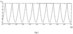
- control 5 is used to adjust the amplitude I A (as in the Figure 2 shown) and adjust the phase position of the id current with respect to the AC mains voltage U N , the generated pulsating electrical energy being stored as magnetic energy in the EC motor 1 by regulating the id current component by means of the primary control 4.
- the undesired pulsation of the motor torque caused by the pulsation of the direct voltage, as a result of a deliberately undersized capacitor capacity, can be compensated for by the controller 4, 5 of the id current.
- the id current curve required for this is shown in the Figure 2 can be seen, with only negative current pulses being generated.
Landscapes
- Engineering & Computer Science (AREA)
- Power Engineering (AREA)
- Control Of Motors That Do Not Use Commutators (AREA)
- Rectifiers (AREA)
- Control Of Ac Motors In General (AREA)
Description
- Die Erfindung betrifft ein Verfahren zur Reduzierung der Drehmomentwelligkeit eines einphasig gespeisten EC-Motors.
- Das Schaltungsprinzip der in Ventilatoren meist eingesetzten EC-Motoren ist bekanntermaßen nicht völlig frei von Rückwirkungen auf das Netz. Durch den pulsförmigen Aufnahmestrom von EC-Ventilatoren entstehen Stromoberschwingungen. Diese belasten das Versorgungsnetz und können zu erhöhten Verlusten aufgrund von Blindleistung führen, sogar andere Geräte im Anlagennetz können negativ beeinflusst werden. Ferner führen diese auch zu einer nicht ausreichend konstanten Stromaufnahme und damit Drehmomentwelligkeit der Motoren. Um dies zu verhindern, gibt es diverse, in der Elektronik integrierte Lösungen, wie z. B. die aktive oder passive Leistungsfaktorkorrektur (PFC -Power Factor Correction).
- Um bei einphasig-netzgespeisten EC-Motoren einen zeitlich sinusförmigen Verlauf des Netzstromes zu erhalten, wird dafür klassisch eine PFC-Schaltung vorgesehen, welche an ihrem Ausgang ein geglättete Gleichspannung bereitstellt. Bei einer bekannten Methode wird z. B. der pulsförmige Aufnahmestrom der EC-Motoren in einen sinusförmigen Strom umgewandelt und dann in einem nachfolgenden zweiten Schritt die Lage der Stromkurve so verschoben, dass sie gleichphasig zur Spannung ist. Auf diese Weise können z. B. die Oberschwingungsanteile im Eingangsstrom stark reduziert werden.
- Um dies zu bewerkstelligen benötigt die PFC-Schaltung einen ausreichend groß bemessenen Elektrolytkondensator im Zwischenkreis. Bei Spannungszwischenkreis - Umrichtern werden solche Kondensatoren als Energiespeicher zur Entkopplung des lastseitigen und des netzseitigen Stromrichters eingesetzt. Reduziert man jedoch die Kapazität des Zwischenkreiskondensators oder lässt diesen, wie beim "schlanken Zwischenkreis" komplett entfallen, erhält man am Ausgang der PFC-Schaltung eine pulsierende Gleichspannung mit überlagerter Wechselspannung, die zu einer Drehmomentwelligkeit führt.
- Die
EP 0 802 623 A1 offenbart z. B. einen Frequenzumrichter, der mit einer Gleichspannungsquelle versorgt wird und wobei der Umrichter einen Zwischenspeicher zum Speichern von Kommutierungsenergie aufgrund von Umladevorgängen in einzelnen Phasenwicklungen umfasst. - Aus der
EP 0 738 035 A2 ist es bekannt, einen Frequenzumrichter ohne Glättungskondensator auszubilden. Hierbei wird die Energie während der Umladevorgänge in einem Kondensator zwischengespeichert, der zwischen dem geschalteten Minus-Pol des Phasenanschlusses und dem Minus-Pol des Gleichspannungs-Zwischenkreises geschaltet ist. Auch dieser als Zwischenspeicher fungierende Kondensator muss für die gesamte Spannung des Zwischenkreises, die sich aus der Summe des Scheitelwertes der Netzspannung und dem Spannungsanteil einer beim Kommutieren abmagnetisierenden Spule zusammensetzt, dimensioniert sein und kann nicht beliebig verkleinert werden, ohne dass es zu der besagten unerwünschten Welligkeit kommt. - Aus der
DE 44 06 546 B4 ist ein Frequenzumrichter zum Betreiben eines Motors bekannt, der einen gleichgerichteten und nahezu vollständig geglätteten Gleichspannungszwischenkreis umfasst. Eine Kombination aus Trafo und Kondensator bildet hier den gemeinsamen Zwischenspeicher für die Energie während der Umladevorgänge. Hierbei wird der Trafo mittels eines weiteren Schalters getaktet, so dass eine optimierte Übertragung der Energie während der Umladevorgänge bereitgestellt wird. Aufgrund des zusätzlichen Übertragers ist der Frequenzumrichter aber recht aufwändig und teuer. - Andere alternative Lösungen sehen zum Beispiel die Nutzung des Stators des EC-Motors als Kondensator (Statorkondensator) vor oder die Nutzung der Nullinduktivität als Zwischenspeicher.
- Weiterer druckschriftlicher Stand der Technik im vorliegenden technischen Gebiet, welcher der Oberbegriff des Anspruchs 1 wiederspiegelt, ist in den Dokumenten
EP 2 276 162 A1, Ralf Rothfuss et al : "Flachheit: Ein neuer Zugang zur Steuerung und Regelung nichtlinearer Systeme",EP 0 977 337 A2 undDE 10 2012 010092 A1 offenbart. - Da die Glättungskondensatoren kostentreibend sind, ist es aber wünschenswert eine Reduzierung der verbauten Kapazität bei EC-Motoren mit Leistungsfaktorkorrektur (PFC) am Netzeingang zu realisieren. Für die Erzeugung eines konstanten Motordrehmomentes, was für einen geräuscharmen Ventilatorbetrieb zwingend notwendig ist, benötigt man eine konstante Gleichspannung, welche zu einer konstanten Motorleistung und damit bei konstanter Drehzahl zu einem konstanten Motordrehmoment führt. Die elektrische Leistung ist jedoch bei einer pulsierenden Gleichspannung nur dann konstant, wenn auch der Strom so pulsiert, dass wiederum das Produkt aus Strom und Spannung konstant ist.
- Es ist daher Aufgabe der vorliegenden Erfindung, vorbesagte Nachteile zu überwinden und eine kostengünstige und zuverlässige Lösung für einphasig gespeiste EC-Motoren mit Leistungsfaktorkorrektur (PFC) am Netzeingang bereit zu stellen.
- Diese Aufgabe wird durch die Merkmalskombination gemäß Anspruch 1 und Anspruch 7 gelöst.
- Ein Grundgedanke der vorliegenden Erfindung besteht darin, dass die Speicherung von Energie im Motor und nicht nur oder ausschließlich in einem Elektrolytkondensator erfolgt und zwar durch die gezielte Vorgabe einer dynamischen id-Strom-Trajektorie. Dabei kann die Anpassung der Stromaufnahme bei EC-Motoren bei pulsierender Gleichspannung am Wechselrichtereingang durch die Anpassung des feldbildenden id-Stromes erreicht werden.
- Erfindungsgemäß wird hierzu ein Verfahren durch die Merkmale des unabhängigen Anspruchs 1 definiert.
- Anders als bei PFC-Schaltungen mit einem ausreichend groß dimensionierten Zwischenkreiskondensator zum Speichern der (elektrischen) Energie, ist vorliegend der Kondensator bestimmungsgemäß unterdimensioniert, so dass die elektrische Energie anderweitig gespeichert werden muss und zwar, wie erfindungsgemäß vorgeschlagen, im EC-Motor als Feldenergie in den Motorwicklungen. So bewirkt eine Änderung des id-Stromes eine Speicherung von magnetischer Energie.
- Die durch die Pulsation der Gleichspannung hervorgerufene unerwünschte Pulsation des Motordrehmomentes, infolge von unterdimensionierten Elektrolytkondensatoren, kann somit durch eine Steuerung des id-Stromes erfindungsgemäß ausgeglichen werden. Um den hierzu erforderlichen hochdynamischen Stromverlauf zu realisieren, wird im Zusammenhang mit der Reduzierung der PFC-Kapazitäten, eine Trajektorien gesteuerte flachheitsbasierte nichtlineare Regelung im Zustandsraum verwendet. Die Verwendung dieses Regelungskonzepts ermöglichte es den erforderlichen id-Stromverlauf, exakt bzw. gewünscht einzuregeln.
- Gemäß einer bevorzugten Ausgestaltung der Erfindung ist vorgesehen, dass die Steuerung zur Speicherung der Energie die Anpassung des feldbildenden id-Stromanteils umfasst. Wobei erfindungsgemäß zur Steuerung des id-Stroms die zuvor genannte Trajektorien gesteuerte flachheitsbasierte nichtlineare Regelung im Zustandsraum verwendet wird.
- In einer vorteilhaften Ausgestaltung der Erfindung ist vorgesehen, dass die Frequenz der id-Strom-Trajektorie der doppelten Netzfrequenz der Netzwechselspannung UN entspricht und mit der Netzfrequenz synchronisiert wird.
- Weiter vorteilhaft ist es, wenn die Amplitude und Phasenlage des id-Stroms gegenüber der Netzwechselspannung UN von einer zweiten, der primären Regelung überlagerten Regelung so eingestellt wird, dass die Pulsation der im Zwischenkreis erzeugten Gleichspannung reduziert oder (vorzugsweise auf ein Minimum) minimiert wird.
- Da es sich bei dem vorgeschlagenen Regelungskonzept um einen Regelung handelt, welche zwei Ausgangsgrößen (Amplitude des id-Stromes und die Phasenlage zur Netzspannung) sowie eine Eingangsgröße (Pulsationsamplitude) handelt, wird als zusätzliche Regelbedingung gefordert, dass die Amplitude des id-Stromes möglichst klein zu halten ist, um die Verluste durch den zusätzlichen id-Strom zu minimieren. Hierzu wird die Amplitude des id-Stromes bei der Regelung im möglichen Amplituden-Phasenlagen-Regelfeld möglichst klein gewählt wird.
- Eine weitere vorteilhafte Ausgestaltung der Erfindung sieht vor, dass die Amplitude des id-Stroms negativ eingeprägt wird, um durch die dadurch erzielte Feldschwächung eine Reduzierung der Eisenverluste im EC-Motor zu erhalten. In einem besonders günstigen Fall heben sich die zusätzlichen Verluste durch den id-Strom mit der Reduzierung der Eisenverluste durch den id-Strom genau auf und der Vorteil der Reduzierung der Kapazität des Zwischenkreiskondensators geht nicht auf Kosten eines schlechteren Wirkungsgrades des EC-Motors.
- Ein weiterer Aspekt der vorliegenden Erfindung betrifft einen einphasig speisbarer EC-Motor, welcher durch die Merkmale des unabhängigen Anspruchs 7 definiert ist.
- Mit Vorteil ist der EC-Motor so ausgebildet, dass eine zweite Regelung vorgesehen ist, um die Amplitude und Phasenlage des id-Stroms gegenüber der Netzwechselspannung UN einzustellen.
- In einer weiteren vorteilhaften Ausgestaltung der Erfindung ist vorgesehen, dass die zweite Regelung zur Anpassung der Phasenlage und Amplitude des id-Stroms so ausgebildet ist, dass damit die Pulsation einer im Zwischenkreis erzeugten Gleichspannung reduziert oder minimiert wird.
- Andere vorteilhafte Weiterbildungen der Erfindung sind in den Unteransprüchen gekennzeichnet bzw. werden nachstehend zusammen mit der Beschreibung der bevorzugten Ausführung der Erfindung anhand der Figuren näher dargestellt. Es zeigen:
- Fig. 1
- eine schematische Ansicht eines erfindungsgemäßen EC-Motors und
- Fig. 2
- eine Abbildung des Verlaufes des id-Stromes über die Zeit.
- Im Folgenden wird die Erfindung mit Bezug auf die
Figuren 1 und2 anhand eines exemplarischen Ausführungsbeispiels der Erfindung näher beschrieben. - In der
Fig. 1 wird hierzu eine schematische Ansicht eines EC-Motors 1 für einen Ventilator gezeigt. Der EC-Motor 1 ist mit einer Schaltungsanordnung 1a verbunden, umfassend einen Zwischenkreis Z (bzw. eine Zwischenkreisschaltung Z) zum Erzeugen der Zwischenkreisgleichspannung UZK, wobei der Zwischenkreis mit einem Zwischenkreiskondensator CZ ausgebildet ist. Ferner verfügt die Schaltungsanordnung 1a über einen Netzeingang 2 und einen Gleichrichter 8. Die Zwischenkreisschaltung Z ist über eine Kommutierungselektronik 7 mit dem EC-Motor 1 verbunden. Die Zwischenkreisschaltung Z besitzt im Nennbetrieb die Nennspannung UZK, die von der Netzeingangsschaltung 2a und dem Gleichrichter 8 erzeugt wird. Vor der Zwischenkreisschaltung Z ist eine Leistungsfaktorkorrekturschaltung (PFC) vorgesehen. - Die Kapazität des Kondensators CZ ist dabei so bemessen, dass beim Anlegen einer Netzwechselspannung UN eine pulsierende Gleichspannung im Zwischenkreis Z erzeugt wird.
- Zur Reduzierung der Wechselspannungsanteile in der pulsierenden Gleichspannung ist eine primäre Regelungseinrichtung 4 und eine sekundäre bzw. weitere Regelung 5 ausgebildet, um den Motorstrom zu regeln. Dabei berücksichtigt die Regelung 4 eine id-Sollwertvorgabe id-S, eine Solldrehzahl w und eine Trajektorienplanung TP, bei der die Drehzahl-Vorgabe der id-Stromverlauf und der Drehwinkel DW als Parameter verwendet werden. Daraus werden die Trajektorienparameter TPp erzeugt und zu einem flachheitsbasierendem Zustandsregler FZ mit Beobachter übergeben. Der flachheitsbasierendem Zustandsregler FZ mit Beobachter erhält nach einer Clark/Park Transformation C/P in die Größen id-Mess und iq-Mess. Die Spannungsgrößen ud und uq werden von dem flachheitsbasierenden Zustandsregler FZ an das Clark-Park-Stellglied P/C übergeben, das zusätzlich die Größen wie Winkelstellung, sowie Plus und Minus der Zwischenkreisspannung UZK verarbeitet, um daraus die Spannungsgrößen ua, ub und uc zu gewinnen. Diese werde mittels einer 3-phasigen Strommessung SM an den Motor übergeben. Die 3-phasigen Strommessung SM übergibt dabei den Stromwert labc zurück an das C/P Stellglied.
- Es erfolgt somit die Regelung des id-Stromanteils derart, dass die pulsierende elektrische Energie als magnetische Energie im EC-Motor 1 zumindest für eine vorgegebene Zeitspanne gespeichert werden kann.
- Ferner dient die Regelung 5, um die Amplitude IA (wie in der
Figur 2 dargestellt) und Phasenlage des id-Stroms gegenüber der Netzwechselspannung UN einzustellen, wobei die erzeugte pulsierende elektrische Energie durch die Regelung des id-Stromanteils mittels der primären Regelung 4 als magnetische Energie im EC-Motor 1 gespeichert wird. Die durch die Pulsation der Gleichspannung hervorgerufene unerwünschte Pulsation des Motordrehmomentes, infolge einer bewusst unterdimensionierten Kondensatorenkapazität, kann durch die Steuerung 4, 5 des id-Stromes ausgeglichen werden. Der dazu benötigte id-Stromverlauf ist in derFigur 2 zu sehen, wobei nur negative Stromimpulse erzeugt werden.
Claims (9)
- Verfahren zur Reduzierung der Drehmomentwelligkeit und Geräuschentwicklung eines einphasig gespeisten EC-Motors (1) mit einer Zwischenspeicherung von elektrischer Energie in dem EC-Motor (1), der mit einer, einen Kondensator (3) aufweisenden Leistungsfaktorkorrekturschaltung (PFC) am Netzeingang (2) für eine bestimmte Netzwechselspannung UN ausgebildet ist, wobei die Kapazität des Kondensators (CZ) so bemessen ist, dass beim Anlegen der Netzwechselspannung UN eine pulsierende Gleichspannung in einem Zwischenkreis (Z) erzeugt wird, wobei die dadurch erzeugte pulsierende elektrische Energie durch eine primäre Regelung (4) des id-Stromanteils als magnetische Energie im EC-Motor (1) zumindest für eine vorgegebene Zeitspanne gespeichert wird, dadurch gekennzeichnet, dass zur Steuerung des id-Stroms eine Trajektorien gesteuerte flachheitsbasierte nichtlineare Regelung im Zustandsraum verwendet wird.
- Verfahren nach Anspruch 1, dadurch gekennzeichnet, dass die Steuerung (4) zur Speicherung der Energie die Anpassung des feldbildenden id-Stromanteils umfasst.
- Verfahren nach Anspruch 1 oder 2, dadurch gekennzeichnet, dass die Frequenz der id-Strom-Trajektorie der doppelten Netzfrequenz der Netzwechselspannung UN entspricht und mit der Netzfrequenz synchronisiert wird.
- Verfahren nach einem der vorhergehenden Ansprüche, dadurch gekennzeichnet, dass die Amplitude und Phasenlage des id-Stroms gegenüber der Netzwechselspannung UN von einer zweiten, der primären Regelung überlagerten id-Sollwertvorgabe so eingestellt wird, dass die Pulsation der im Zwischenkreis (Z) erzeugten Gleichspannung reduziert oder minimiert wird.
- Verfahren nach Anspruch 4, dadurch gekennzeichnet, dass die Amplitude des id-Stromes bei der Regelung im möglichen Amplituden-Phasenlagen-Regelfeld möglichst klein gewählt wird.
- Verfahren nach einem der vorhergehenden Ansprüche, dadurch gekennzeichnet, dass die Amplitude des id-Stroms negativ eingeprägt wird, um durch die dadurch erzielte Feldschwächung eine Reduzierung der Eisenverluste im EC-Motor (1) zu erhalten.
- Einphasig speisbarer EC-Motor (1) mit einer Schaltungsanordnung (1a) mit einem Zwischenkreis (Z) umfassend:a. einen Netzeingang (2) zum Anschluss an wenigstens eine bestimmte Netzwechselspannung UN,b. eine netzeingangsseitige Leistungsfaktorkorrekturschaltung (PFC) mit einem Kondensator (CZ), wobei die Kapazität des Kondensators (CZ) so bemessen ist, dass beim Anlegen einer Netzwechselspannung UN eine pulsierende Gleichspannung UZK im Zwischenkreis (Z) erzeugt wird, gekennzeichnet durchc. eine primäre Regelungseinrichtung (4) umfassend eine Trajektorienplanung (TP) und einen flachheitsbasierenden Zustandsregler (FZ) ausgebildet, zur Regelung des id-Stromanteils derart, dass die pulsierende elektrische Energie als magnetische Energie im EC-Motor (1) zumindest für eine vorgegebene Zeitspanne gespeichert werden kann.
- EC-Motor (1) nach Anspruch 7, dadurch gekennzeichnet, dass eine zweite Regelung (5) vorgesehen ist, um die Amplitude (lA) und Phasenlage des id-Stroms gegenüber der Netzwechselspannung UN einzustellen.
- EC-Motor (1) nach Anspruch 8, dadurch gekennzeichnet, dass die zweite Regelung (5) zur Anpassung der Phasenlage und Amplitude des id-Stroms so ausgebildet ist, dass damit die Pulsation einer im Zwischenkreis (Z) erzeugten Gleichspannung reduziert oder minimiert wird.
Applications Claiming Priority (2)
| Application Number | Priority Date | Filing Date | Title |
|---|---|---|---|
| DE102017126150.8A DE102017126150A1 (de) | 2017-11-08 | 2017-11-08 | Kapazitätsreduzierung |
| PCT/EP2018/080395 WO2019091996A1 (de) | 2017-11-08 | 2018-11-07 | Kapazitätsreduzierung |
Publications (2)
| Publication Number | Publication Date |
|---|---|
| EP3610570A1 EP3610570A1 (de) | 2020-02-19 |
| EP3610570B1 true EP3610570B1 (de) | 2021-11-03 |
Family
ID=64184091
Family Applications (1)
| Application Number | Title | Priority Date | Filing Date |
|---|---|---|---|
| EP18799749.9A Active EP3610570B1 (de) | 2017-11-08 | 2018-11-07 | Kapazitätsreduzierung |
Country Status (5)
| Country | Link |
|---|---|
| US (1) | US11362603B2 (de) |
| EP (1) | EP3610570B1 (de) |
| CN (1) | CN208508827U (de) |
| DE (1) | DE102017126150A1 (de) |
| WO (1) | WO2019091996A1 (de) |
Cited By (1)
| Publication number | Priority date | Publication date | Assignee | Title |
|---|---|---|---|---|
| EP4734356A1 (de) | 2024-10-24 | 2026-04-29 | ebm-papst Mulfingen GmbH & Co. KGaA & Co. KG | Vorrichtung und verfahren zum betreiben eines elektromotors sowie system aufweisend die vorrichtung und den elektromotor |
Families Citing this family (5)
| Publication number | Priority date | Publication date | Assignee | Title |
|---|---|---|---|---|
| DE102019204576B4 (de) * | 2019-04-01 | 2021-03-11 | Robert Bosch Gmbh | Verfahren zur Reduktion von Drehmomentschwankungen einer elektrischen Drehstrommaschine eines Lenksystems |
| DE102019206872A1 (de) | 2019-05-13 | 2020-11-19 | Rolls-Royce Deutschland Ltd & Co Kg | Minimalistischer Stromrichter und Fahrzeug mit einem Stromrichter |
| US12399483B2 (en) * | 2019-10-21 | 2025-08-26 | Semiconductor Components Industries, Llc | Systems and methods for system optimization and/or failure detection |
| ES2972062T3 (es) * | 2020-04-01 | 2024-06-11 | Siemens Ag | Dispositivo de control para un convertidor de circuito intermedio y un convertidor de circuito intermedio |
| DE102023131705A1 (de) | 2023-11-14 | 2025-05-15 | Ebm-Papst Mulfingen Gmbh & Co. Kg | Mehrmotorenumrichter |
Citations (2)
| Publication number | Priority date | Publication date | Assignee | Title |
|---|---|---|---|---|
| DE19834315A1 (de) * | 1998-07-30 | 2000-02-03 | Ako Werke Gmbh & Co | Schaltungsanordnung zur Messung und Begrenzung von Strömen in Umrichtern zur Speisung von Motoren |
| EP2276162B1 (de) * | 2009-07-17 | 2012-10-03 | ebm-papst Mulfingen GmbH & Co. KG | Verfahren und Steuersystem zum Ansteuern eines bürstenlosen Elektromotors |
Family Cites Families (11)
| Publication number | Priority date | Publication date | Assignee | Title |
|---|---|---|---|---|
| GB2275836B (en) | 1993-02-27 | 1997-07-30 | Gold Star Co | A switched reluctance motor driving circuit |
| GB9507540D0 (en) | 1995-04-11 | 1995-05-31 | Switched Reluctance Drives Ltd | Control circuit and system for a switched reluctance machine and method of operating |
| GB9608216D0 (en) | 1996-04-19 | 1996-06-26 | Switched Reluctance Drives Ltd | Converter circuit for a polyphase switched inductive load |
| US5994869A (en) * | 1997-12-05 | 1999-11-30 | General Electric Company | Power conversion circuit for a motor |
| US7495410B2 (en) * | 2007-01-30 | 2009-02-24 | Rockwell Automation Technologies, Inc. | Systems and methods for improved motor drive power factor control |
| US8698433B2 (en) * | 2009-08-10 | 2014-04-15 | Emerson Climate Technologies, Inc. | Controller and method for minimizing phase advance current |
| JP5337663B2 (ja) * | 2009-10-15 | 2013-11-06 | 株式会社東芝 | ドライバ回路 |
| JP5212491B2 (ja) * | 2011-01-18 | 2013-06-19 | ダイキン工業株式会社 | 電力変換装置 |
| EP2482442B2 (de) * | 2011-01-27 | 2021-02-24 | ebm-papst Mulfingen GmbH & Co. KG | Verfahren und Steuersystem zum Ansteuern eines bürstenlosen Elektromotors |
| DE102012010092A1 (de) * | 2011-05-30 | 2012-12-06 | Secop Gmbh | Regler und Verfahren zur Regelung eines Motors für einen Verdichter |
| US9914362B2 (en) * | 2013-04-15 | 2018-03-13 | Virginia Tech Intellectual Properties, Inc. | Energy storage for power factor correction in battery charger for electric-powered vehicles |
-
2017
- 2017-11-08 DE DE102017126150.8A patent/DE102017126150A1/de not_active Withdrawn
- 2017-12-19 CN CN201721781056.0U patent/CN208508827U/zh active Active
-
2018
- 2018-11-07 EP EP18799749.9A patent/EP3610570B1/de active Active
- 2018-11-07 WO PCT/EP2018/080395 patent/WO2019091996A1/de not_active Ceased
- 2018-11-07 US US16/762,848 patent/US11362603B2/en active Active
Patent Citations (3)
| Publication number | Priority date | Publication date | Assignee | Title |
|---|---|---|---|---|
| DE19834315A1 (de) * | 1998-07-30 | 2000-02-03 | Ako Werke Gmbh & Co | Schaltungsanordnung zur Messung und Begrenzung von Strömen in Umrichtern zur Speisung von Motoren |
| EP0977337B1 (de) * | 1998-07-30 | 2011-03-09 | Diehl AKO Stiftung & Co. KG | Schaltungsanordnung zur Messung und Begrenzung von Strömen in Umrichtern zur Speisung von Motoren |
| EP2276162B1 (de) * | 2009-07-17 | 2012-10-03 | ebm-papst Mulfingen GmbH & Co. KG | Verfahren und Steuersystem zum Ansteuern eines bürstenlosen Elektromotors |
Cited By (2)
| Publication number | Priority date | Publication date | Assignee | Title |
|---|---|---|---|---|
| EP4734356A1 (de) | 2024-10-24 | 2026-04-29 | ebm-papst Mulfingen GmbH & Co. KGaA & Co. KG | Vorrichtung und verfahren zum betreiben eines elektromotors sowie system aufweisend die vorrichtung und den elektromotor |
| DE102024130971A1 (de) | 2024-10-24 | 2026-04-30 | ebm-papst Mulfingen GmbH & Co. KGaA & Co. KG | Vorrichtung und Verfahren zum Betreiben eines Elektromotors sowie System aufweisend die Vorrichtung und den Elektromotor |
Also Published As
| Publication number | Publication date |
|---|---|
| US11362603B2 (en) | 2022-06-14 |
| US20200287483A1 (en) | 2020-09-10 |
| DE102017126150A1 (de) | 2019-05-09 |
| CN208508827U (zh) | 2019-02-15 |
| WO2019091996A1 (de) | 2019-05-16 |
| EP3610570A1 (de) | 2020-02-19 |
Similar Documents
| Publication | Publication Date | Title |
|---|---|---|
| EP3610570B1 (de) | Kapazitätsreduzierung | |
| EP2276162B1 (de) | Verfahren und Steuersystem zum Ansteuern eines bürstenlosen Elektromotors | |
| EP2979352B1 (de) | Vorrichtung, insbesondere maschine oder anlage, und verfahren zum betreiben einer vorrichtung | |
| DE202017106787U1 (de) | Vorrichtung zur Kapazitätsreduzierung | |
| EP3642932A1 (de) | Vorrichtung und verfahren zur aktiven erzeugung und einprägung von blindleistung in induktive übertragungssystem | |
| CH714180B1 (de) | Konverter zur Übertragung von elektrischer Energie zwischen einem DC und einem AC-System. | |
| EP2856625B1 (de) | Spannungsversorgung für einen wechselrichter | |
| DE19531210A1 (de) | Steuersystem für einphasigen PWM-Wandler | |
| DE2434316A1 (de) | Statische leistungsumformungseinrichtung | |
| WO2013113540A2 (de) | Wahlweise steuerung eines wechselstrommotors oder gleichstrommotors | |
| DE112018008052B4 (de) | Leistungswandlersystem | |
| WO2017050960A1 (de) | Verfahren zum betrieb eines modularen multilevel-stromrichters, modularer multilevel-stromrichter sowie computerprogramm | |
| EP3043461B1 (de) | Versorgungsschaltung zur versorgung eines schweissgerätes | |
| WO2023066952A1 (de) | Verfahren zur regelung eines resonanzwandlers | |
| EP1619781B1 (de) | Schaltungsanordnung für einen Umrichter | |
| DE10044574A1 (de) | Schaltungsanordnung zum variablen Steuern von Wechselstromverbrauchern | |
| WO2010088979A1 (de) | Verfahren zur regelung eines selbstgeführten netzstromrichters eines spannungszwischenkreis-umrichters | |
| DE102012207263B4 (de) | Versorgungsstrang, Versorgungssystem und Verfahren zum Betreiben eines elektrischen Antriebs | |
| EP2778426B1 (de) | Elektromotor mit leistungselektronischem Umrichtersystem und daraus gespeister aktiver Kühleinrichtung | |
| EP2975747B1 (de) | Verbessern einer Spannung einer Stromversorgungsverbindung | |
| WO2005114830A1 (de) | Frequenzumformeinrichtung für einen windenergiepark sowie verfahren zum betrieb einer solchen einrichtung | |
| DE20023570U1 (de) | Gargerät mit Spannungs-, Phasen- und/oder Frequenzumwandler | |
| EP2677622A2 (de) | Verfahren und eine Vorrichtung zum Einspeisen von elektrischer Leistung in ein elektrisches Energieversorgungsnetz | |
| DE112024002495T5 (de) | Wechselstrom-Gleichstrom-Wandler, Drehmaschinenantrieb und Kühlkreislauf-Anwendungsgerät | |
| EP4734356A1 (de) | Vorrichtung und verfahren zum betreiben eines elektromotors sowie system aufweisend die vorrichtung und den elektromotor |
Legal Events
| Date | Code | Title | Description |
|---|---|---|---|
| STAA | Information on the status of an ep patent application or granted ep patent |
Free format text: STATUS: UNKNOWN |
|
| STAA | Information on the status of an ep patent application or granted ep patent |
Free format text: STATUS: THE INTERNATIONAL PUBLICATION HAS BEEN MADE |
|
| PUAI | Public reference made under article 153(3) epc to a published international application that has entered the european phase |
Free format text: ORIGINAL CODE: 0009012 |
|
| STAA | Information on the status of an ep patent application or granted ep patent |
Free format text: STATUS: REQUEST FOR EXAMINATION WAS MADE |
|
| 17P | Request for examination filed |
Effective date: 20191115 |
|
| AK | Designated contracting states |
Kind code of ref document: A1 Designated state(s): AL AT BE BG CH CY CZ DE DK EE ES FI FR GB GR HR HU IE IS IT LI LT LU LV MC MK MT NL NO PL PT RO RS SE SI SK SM TR |
|
| AX | Request for extension of the european patent |
Extension state: BA ME |
|
| DAV | Request for validation of the european patent (deleted) | ||
| DAX | Request for extension of the european patent (deleted) | ||
| REG | Reference to a national code |
Ref country code: DE Ref legal event code: R079 Ref document number: 502018007709 Country of ref document: DE Free format text: PREVIOUS MAIN CLASS: H02P0006260000 Ipc: H02P0021050000 |
|
| GRAP | Despatch of communication of intention to grant a patent |
Free format text: ORIGINAL CODE: EPIDOSNIGR1 |
|
| STAA | Information on the status of an ep patent application or granted ep patent |
Free format text: STATUS: GRANT OF PATENT IS INTENDED |
|
| RIC1 | Information provided on ipc code assigned before grant |
Ipc: H02P 6/10 20060101ALI20210426BHEP Ipc: H02P 21/05 20060101AFI20210426BHEP |
|
| INTG | Intention to grant announced |
Effective date: 20210531 |
|
| GRAJ | Information related to disapproval of communication of intention to grant by the applicant or resumption of examination proceedings by the epo deleted |
Free format text: ORIGINAL CODE: EPIDOSDIGR1 |
|
| STAA | Information on the status of an ep patent application or granted ep patent |
Free format text: STATUS: REQUEST FOR EXAMINATION WAS MADE |
|
| GRAP | Despatch of communication of intention to grant a patent |
Free format text: ORIGINAL CODE: EPIDOSNIGR1 |
|
| STAA | Information on the status of an ep patent application or granted ep patent |
Free format text: STATUS: GRANT OF PATENT IS INTENDED |
|
| GRAS | Grant fee paid |
Free format text: ORIGINAL CODE: EPIDOSNIGR3 |
|
| GRAA | (expected) grant |
Free format text: ORIGINAL CODE: 0009210 |
|
| STAA | Information on the status of an ep patent application or granted ep patent |
Free format text: STATUS: THE PATENT HAS BEEN GRANTED |
|
| INTC | Intention to grant announced (deleted) | ||
| INTG | Intention to grant announced |
Effective date: 20210916 |
|
| AK | Designated contracting states |
Kind code of ref document: B1 Designated state(s): AL AT BE BG CH CY CZ DE DK EE ES FI FR GB GR HR HU IE IS IT LI LT LU LV MC MK MT NL NO PL PT RO RS SE SI SK SM TR |
|
| REG | Reference to a national code |
Ref country code: GB Ref legal event code: FG4D Free format text: NOT ENGLISH |
|
| REG | Reference to a national code |
Ref country code: AT Ref legal event code: REF Ref document number: 1444895 Country of ref document: AT Kind code of ref document: T Effective date: 20211115 Ref country code: CH Ref legal event code: EP |
|
| REG | Reference to a national code |
Ref country code: DE Ref legal event code: R096 Ref document number: 502018007709 Country of ref document: DE |
|
| REG | Reference to a national code |
Ref country code: IE Ref legal event code: FG4D Free format text: LANGUAGE OF EP DOCUMENT: GERMAN |
|
| REG | Reference to a national code |
Ref country code: NL Ref legal event code: FP |
|
| REG | Reference to a national code |
Ref country code: LT Ref legal event code: MG9D |
|
| PG25 | Lapsed in a contracting state [announced via postgrant information from national office to epo] |
Ref country code: RS Free format text: LAPSE BECAUSE OF FAILURE TO SUBMIT A TRANSLATION OF THE DESCRIPTION OR TO PAY THE FEE WITHIN THE PRESCRIBED TIME-LIMIT Effective date: 20211103 Ref country code: LT Free format text: LAPSE BECAUSE OF FAILURE TO SUBMIT A TRANSLATION OF THE DESCRIPTION OR TO PAY THE FEE WITHIN THE PRESCRIBED TIME-LIMIT Effective date: 20211103 Ref country code: FI Free format text: LAPSE BECAUSE OF FAILURE TO SUBMIT A TRANSLATION OF THE DESCRIPTION OR TO PAY THE FEE WITHIN THE PRESCRIBED TIME-LIMIT Effective date: 20211103 Ref country code: BG Free format text: LAPSE BECAUSE OF FAILURE TO SUBMIT A TRANSLATION OF THE DESCRIPTION OR TO PAY THE FEE WITHIN THE PRESCRIBED TIME-LIMIT Effective date: 20220203 |
|
| PG25 | Lapsed in a contracting state [announced via postgrant information from national office to epo] |
Ref country code: IS Free format text: LAPSE BECAUSE OF FAILURE TO SUBMIT A TRANSLATION OF THE DESCRIPTION OR TO PAY THE FEE WITHIN THE PRESCRIBED TIME-LIMIT Effective date: 20220303 Ref country code: SE Free format text: LAPSE BECAUSE OF FAILURE TO SUBMIT A TRANSLATION OF THE DESCRIPTION OR TO PAY THE FEE WITHIN THE PRESCRIBED TIME-LIMIT Effective date: 20211103 Ref country code: PT Free format text: LAPSE BECAUSE OF FAILURE TO SUBMIT A TRANSLATION OF THE DESCRIPTION OR TO PAY THE FEE WITHIN THE PRESCRIBED TIME-LIMIT Effective date: 20220303 Ref country code: PL Free format text: LAPSE BECAUSE OF FAILURE TO SUBMIT A TRANSLATION OF THE DESCRIPTION OR TO PAY THE FEE WITHIN THE PRESCRIBED TIME-LIMIT Effective date: 20211103 Ref country code: NO Free format text: LAPSE BECAUSE OF FAILURE TO SUBMIT A TRANSLATION OF THE DESCRIPTION OR TO PAY THE FEE WITHIN THE PRESCRIBED TIME-LIMIT Effective date: 20220203 Ref country code: LV Free format text: LAPSE BECAUSE OF FAILURE TO SUBMIT A TRANSLATION OF THE DESCRIPTION OR TO PAY THE FEE WITHIN THE PRESCRIBED TIME-LIMIT Effective date: 20211103 Ref country code: HR Free format text: LAPSE BECAUSE OF FAILURE TO SUBMIT A TRANSLATION OF THE DESCRIPTION OR TO PAY THE FEE WITHIN THE PRESCRIBED TIME-LIMIT Effective date: 20211103 Ref country code: GR Free format text: LAPSE BECAUSE OF FAILURE TO SUBMIT A TRANSLATION OF THE DESCRIPTION OR TO PAY THE FEE WITHIN THE PRESCRIBED TIME-LIMIT Effective date: 20220204 Ref country code: ES Free format text: LAPSE BECAUSE OF FAILURE TO SUBMIT A TRANSLATION OF THE DESCRIPTION OR TO PAY THE FEE WITHIN THE PRESCRIBED TIME-LIMIT Effective date: 20211103 |
|
| REG | Reference to a national code |
Ref country code: CH Ref legal event code: PL |
|
| PG25 | Lapsed in a contracting state [announced via postgrant information from national office to epo] |
Ref country code: SM Free format text: LAPSE BECAUSE OF FAILURE TO SUBMIT A TRANSLATION OF THE DESCRIPTION OR TO PAY THE FEE WITHIN THE PRESCRIBED TIME-LIMIT Effective date: 20211103 Ref country code: SK Free format text: LAPSE BECAUSE OF FAILURE TO SUBMIT A TRANSLATION OF THE DESCRIPTION OR TO PAY THE FEE WITHIN THE PRESCRIBED TIME-LIMIT Effective date: 20211103 Ref country code: RO Free format text: LAPSE BECAUSE OF FAILURE TO SUBMIT A TRANSLATION OF THE DESCRIPTION OR TO PAY THE FEE WITHIN THE PRESCRIBED TIME-LIMIT Effective date: 20211103 Ref country code: LU Free format text: LAPSE BECAUSE OF NON-PAYMENT OF DUE FEES Effective date: 20211107 Ref country code: EE Free format text: LAPSE BECAUSE OF FAILURE TO SUBMIT A TRANSLATION OF THE DESCRIPTION OR TO PAY THE FEE WITHIN THE PRESCRIBED TIME-LIMIT Effective date: 20211103 Ref country code: DK Free format text: LAPSE BECAUSE OF FAILURE TO SUBMIT A TRANSLATION OF THE DESCRIPTION OR TO PAY THE FEE WITHIN THE PRESCRIBED TIME-LIMIT Effective date: 20211103 Ref country code: CZ Free format text: LAPSE BECAUSE OF FAILURE TO SUBMIT A TRANSLATION OF THE DESCRIPTION OR TO PAY THE FEE WITHIN THE PRESCRIBED TIME-LIMIT Effective date: 20211103 Ref country code: BE Free format text: LAPSE BECAUSE OF NON-PAYMENT OF DUE FEES Effective date: 20211130 |
|
| REG | Reference to a national code |
Ref country code: BE Ref legal event code: MM Effective date: 20211130 |
|
| REG | Reference to a national code |
Ref country code: DE Ref legal event code: R097 Ref document number: 502018007709 Country of ref document: DE |
|
| PG25 | Lapsed in a contracting state [announced via postgrant information from national office to epo] |
Ref country code: MC Free format text: LAPSE BECAUSE OF FAILURE TO SUBMIT A TRANSLATION OF THE DESCRIPTION OR TO PAY THE FEE WITHIN THE PRESCRIBED TIME-LIMIT Effective date: 20211103 Ref country code: LI Free format text: LAPSE BECAUSE OF NON-PAYMENT OF DUE FEES Effective date: 20211130 Ref country code: CH Free format text: LAPSE BECAUSE OF NON-PAYMENT OF DUE FEES Effective date: 20211130 |
|
| PLBE | No opposition filed within time limit |
Free format text: ORIGINAL CODE: 0009261 |
|
| STAA | Information on the status of an ep patent application or granted ep patent |
Free format text: STATUS: NO OPPOSITION FILED WITHIN TIME LIMIT |
|
| 26N | No opposition filed |
Effective date: 20220804 |
|
| PG25 | Lapsed in a contracting state [announced via postgrant information from national office to epo] |
Ref country code: IE Free format text: LAPSE BECAUSE OF NON-PAYMENT OF DUE FEES Effective date: 20211107 Ref country code: AL Free format text: LAPSE BECAUSE OF FAILURE TO SUBMIT A TRANSLATION OF THE DESCRIPTION OR TO PAY THE FEE WITHIN THE PRESCRIBED TIME-LIMIT Effective date: 20211103 |
|
| PG25 | Lapsed in a contracting state [announced via postgrant information from national office to epo] |
Ref country code: SI Free format text: LAPSE BECAUSE OF FAILURE TO SUBMIT A TRANSLATION OF THE DESCRIPTION OR TO PAY THE FEE WITHIN THE PRESCRIBED TIME-LIMIT Effective date: 20211103 |
|
| P01 | Opt-out of the competence of the unified patent court (upc) registered |
Effective date: 20230522 |
|
| PG25 | Lapsed in a contracting state [announced via postgrant information from national office to epo] |
Ref country code: CY Free format text: LAPSE BECAUSE OF FAILURE TO SUBMIT A TRANSLATION OF THE DESCRIPTION OR TO PAY THE FEE WITHIN THE PRESCRIBED TIME-LIMIT Effective date: 20211103 |
|
| PG25 | Lapsed in a contracting state [announced via postgrant information from national office to epo] |
Ref country code: HU Free format text: LAPSE BECAUSE OF FAILURE TO SUBMIT A TRANSLATION OF THE DESCRIPTION OR TO PAY THE FEE WITHIN THE PRESCRIBED TIME-LIMIT; INVALID AB INITIO Effective date: 20181107 |
|
| PG25 | Lapsed in a contracting state [announced via postgrant information from national office to epo] |
Ref country code: MK Free format text: LAPSE BECAUSE OF FAILURE TO SUBMIT A TRANSLATION OF THE DESCRIPTION OR TO PAY THE FEE WITHIN THE PRESCRIBED TIME-LIMIT Effective date: 20211103 |
|
| PG25 | Lapsed in a contracting state [announced via postgrant information from national office to epo] |
Ref country code: MT Free format text: LAPSE BECAUSE OF FAILURE TO SUBMIT A TRANSLATION OF THE DESCRIPTION OR TO PAY THE FEE WITHIN THE PRESCRIBED TIME-LIMIT Effective date: 20211103 |
|
| PG25 | Lapsed in a contracting state [announced via postgrant information from national office to epo] |
Ref country code: TR Free format text: LAPSE BECAUSE OF FAILURE TO SUBMIT A TRANSLATION OF THE DESCRIPTION OR TO PAY THE FEE WITHIN THE PRESCRIBED TIME-LIMIT Effective date: 20211103 |
|
| PGFP | Annual fee paid to national office [announced via postgrant information from national office to epo] |
Ref country code: NL Payment date: 20251119 Year of fee payment: 8 |
|
| PGFP | Annual fee paid to national office [announced via postgrant information from national office to epo] |
Ref country code: DE Payment date: 20251118 Year of fee payment: 8 |
|
| PGFP | Annual fee paid to national office [announced via postgrant information from national office to epo] |
Ref country code: GB Payment date: 20251120 Year of fee payment: 8 |
|
| PGFP | Annual fee paid to national office [announced via postgrant information from national office to epo] |
Ref country code: AT Payment date: 20251117 Year of fee payment: 8 |
|
| PGFP | Annual fee paid to national office [announced via postgrant information from national office to epo] |
Ref country code: IT Payment date: 20251128 Year of fee payment: 8 |
|
| PGFP | Annual fee paid to national office [announced via postgrant information from national office to epo] |
Ref country code: FR Payment date: 20251125 Year of fee payment: 8 |