EP3610488B1 - Hollow core electromagnetic coil - Google Patents
Hollow core electromagnetic coil Download PDFInfo
- Publication number
- EP3610488B1 EP3610488B1 EP19705623.7A EP19705623A EP3610488B1 EP 3610488 B1 EP3610488 B1 EP 3610488B1 EP 19705623 A EP19705623 A EP 19705623A EP 3610488 B1 EP3610488 B1 EP 3610488B1
- Authority
- EP
- European Patent Office
- Prior art keywords
- metal foil
- core substrate
- coil
- core
- hollow
- Prior art date
- Legal status (The legal status is an assumption and is not a legal conclusion. Google has not performed a legal analysis and makes no representation as to the accuracy of the status listed.)
- Active
Links
Images


Classifications
-
- H—ELECTRICITY
- H01—ELECTRIC ELEMENTS
- H01F—MAGNETS; INDUCTANCES; TRANSFORMERS; SELECTION OF MATERIALS FOR THEIR MAGNETIC PROPERTIES
- H01F27/00—Details of transformers or inductances, in general
- H01F27/28—Coils; Windings; Conductive connections
- H01F27/2847—Sheets; Strips
-
- G—PHYSICS
- G06—COMPUTING OR CALCULATING; COUNTING
- G06F—ELECTRIC DIGITAL DATA PROCESSING
- G06F1/00—Details not covered by groups G06F3/00 - G06F13/00 and G06F21/00
- G06F1/16—Constructional details or arrangements
- G06F1/1613—Constructional details or arrangements for portable computers
- G06F1/163—Wearable computers, e.g. on a belt
-
- G—PHYSICS
- G06—COMPUTING OR CALCULATING; COUNTING
- G06F—ELECTRIC DIGITAL DATA PROCESSING
- G06F3/00—Input arrangements for transferring data to be processed into a form capable of being handled by the computer; Output arrangements for transferring data from processing unit to output unit, e.g. interface arrangements
- G06F3/01—Input arrangements or combined input and output arrangements for interaction between user and computer
- G06F3/011—Arrangements for interaction with the human body, e.g. for user immersion in virtual reality
-
- G—PHYSICS
- G06—COMPUTING OR CALCULATING; COUNTING
- G06F—ELECTRIC DIGITAL DATA PROCESSING
- G06F3/00—Input arrangements for transferring data to be processed into a form capable of being handled by the computer; Output arrangements for transferring data from processing unit to output unit, e.g. interface arrangements
- G06F3/01—Input arrangements or combined input and output arrangements for interaction between user and computer
- G06F3/011—Arrangements for interaction with the human body, e.g. for user immersion in virtual reality
- G06F3/012—Head tracking input arrangements
-
- G—PHYSICS
- G06—COMPUTING OR CALCULATING; COUNTING
- G06F—ELECTRIC DIGITAL DATA PROCESSING
- G06F3/00—Input arrangements for transferring data to be processed into a form capable of being handled by the computer; Output arrangements for transferring data from processing unit to output unit, e.g. interface arrangements
- G06F3/01—Input arrangements or combined input and output arrangements for interaction between user and computer
- G06F3/03—Arrangements for converting the position or the displacement of a member into a coded form
- G06F3/033—Pointing devices displaced or positioned by the user, e.g. mice, trackballs, pens or joysticks; Accessories therefor
- G06F3/0346—Pointing devices displaced or positioned by the user, e.g. mice, trackballs, pens or joysticks; Accessories therefor with detection of the device orientation or free movement in a three-dimensional [3D] space, e.g. 3D mice, 6-DOF [six degrees of freedom] pointers using gyroscopes, accelerometers or tilt-sensors
-
- H—ELECTRICITY
- H01—ELECTRIC ELEMENTS
- H01F—MAGNETS; INDUCTANCES; TRANSFORMERS; SELECTION OF MATERIALS FOR THEIR MAGNETIC PROPERTIES
- H01F3/00—Cores, Yokes, or armatures
- H01F3/10—Composite arrangements of magnetic circuits
- H01F3/14—Constrictions; Gaps, e.g. air-gaps
-
- H—ELECTRICITY
- H01—ELECTRIC ELEMENTS
- H01F—MAGNETS; INDUCTANCES; TRANSFORMERS; SELECTION OF MATERIALS FOR THEIR MAGNETIC PROPERTIES
- H01F5/00—Coils
-
- H—ELECTRICITY
- H01—ELECTRIC ELEMENTS
- H01F—MAGNETS; INDUCTANCES; TRANSFORMERS; SELECTION OF MATERIALS FOR THEIR MAGNETIC PROPERTIES
- H01F5/00—Coils
- H01F5/02—Coils wound on non-magnetic supports, e.g. formers
-
- H—ELECTRICITY
- H01—ELECTRIC ELEMENTS
- H01F—MAGNETS; INDUCTANCES; TRANSFORMERS; SELECTION OF MATERIALS FOR THEIR MAGNETIC PROPERTIES
- H01F5/00—Coils
- H01F5/02—Coils wound on non-magnetic supports, e.g. formers
- H01F2005/027—Coils wound on non-magnetic supports, e.g. formers wound on formers for receiving several coils with perpendicular winding axes, e.g. for antennae or inductive power transfer
-
- H—ELECTRICITY
- H01—ELECTRIC ELEMENTS
- H01F—MAGNETS; INDUCTANCES; TRANSFORMERS; SELECTION OF MATERIALS FOR THEIR MAGNETIC PROPERTIES
- H01F27/00—Details of transformers or inductances, in general
- H01F27/28—Coils; Windings; Conductive connections
- H01F27/2847—Sheets; Strips
- H01F2027/2857—Coil formed from wound foil conductor
Definitions
- Electromagnetic (EM) sensing increasingly is used for tracking purposes in virtual reality (VR) and augmented reality (AR) applications.
- Tracking systems using EM sensing typically employ an EM coil to generate a strong EM field, and another EM coil to detect a pose or position based on the generated EM field.
- the transmit-side EM coil generates a three-dimensional (3D) EM field
- the receive-side EM coil outputs one or more voltages, each of the output voltages representing a corresponding positional value with reference to a three degrees of freedom (3DOF) or six degrees of freedom (6DOF) reference frame defined by the 3D EM field.
- Conventional EM coils employ conductive wiring wrapped around a solid ferrite core.
- the solid ferrite core is relatively heavy, which in turn increases the weight of the user-held or user-mounted component employing the conventional EM coil, and thus impacting user comfort.
- the heavy solid core of a conventional EM coil results in the conventional EM coil having higher mass. This results in conventional EM coils being susceptible to dislocation due to drop impacts, with such a dislocation shifting the position of the EM coil and thus negatively impacting its accuracy with regard to factory tracking calibration.
- WO 2016/141373 A1 relates to systems and methods for augmented reality.
- EP 1 806 756 B1 relates to miniature coils on core with printed circuit. An EM coil according to the preamble of present claim 1 is known from these prior art documents.
- FIGS. 1-5 illustrate systems and techniques for tracking in an augmented reality (AR) or virtual reality (VR) system (referred to collectively and in the alternative as an AR/VR system) using a "hollow-core” electromagnetic (EM) coil.
- the term “hollow-core” refers to the use of a core substrate that has less mass than the conventional solid ferrite core or solid ferrous core of comparable external dimensions (i.e., of comparable external volume).
- the core substrate is implemented as a "hollow-core” through the use of materials with a lower density than ferrite or iron, such as plastic materials, through the formation of through-holes or other voids in the body of the core substrate, through the use of a lattice-like hollow-frame structure, or a combination thereof.
- the core substrate is wrapped in three orthogonal directions with strips of thin metal foil, which may be excited with corresponding alternating current (AC) signals to generate a three-dimensional EM field, or which may be used to generate voltages representative of a position and/or orientation of the hollow-core EM coil within a generated 3D EM field.
- the thin metal foil is composed of a metal with high magnetic permeability higher than pure iron, such as an amorphous metal foil or nanocrystalline metal foil.
- the combination of the lightweight nature of the hollow core and the thin and lightweight nature of the thin metal foil while providing high magnetic permeability allows the hollow-core EM coil to provide similar EM field generation or EM field sensing performance of a conventional solid-core EM coil of comparable external dimensions while weighing considerably less.
- the hollow-core EM coil is lighter than conventional EM coils of comparable dimensions, and thus contributes less to user fatigue and is less susceptible to being dislocated as a result of a drop impact.
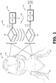
- FIG. 1 illustrates an AR/VR system 100 employing an EM-based tracking system 102 with a hollow-core EM coil in accordance with some embodiments of the present disclosure.
- the AR/VR system 100 includes a head mounted display (HMD) device 104 for displaying AR or VR content and one or more hand-held controllers, such as hand-held controllers 106, 108.
- HMD head mounted display
- hand-held controllers such as hand-held controllers 106, 108.
- the AR/VR system 100 employs the EM-based tracking system 102.
- the EM-based tracking system 102 includes an EM field generation subsystem 110 and an EM field sensing subsystem 112.
- the EM field generation subsystem 110 includes a 3D EM coil 114 and a transmission (TX) controller 116.
- the 3D EM coil 114 is configured to generate a 3D EM field in the X, Y, and Z planes, and the TX controller 116 controls the generation of the EM field in each of these planes through control of AC signals S_X, S_Y, and S_Z input to the EM coil 114.
- the EM field sensing subsystem 112 includes a 3D EM coil 118 and a receive (RX) controller 120.
- the 3D EM coil 118 is configured to sense the generated 3D EM field in each of the X, Y, Z planes and to output a corresponding voltage signal V_X, V_Y, and V_Z to the RX controller 120.
- the RX controller 120 then utilizes these three voltage signals to generate three degrees of freedom (3DOF) (position) or six degrees of freedom (6DOF) (position and orientation) data representing the position and/or orientation of the EM coil 118 with respect to the generated EM field.
- the EM field sensing subsystem 112 is implemented at the HMD device 104 and the EM field generation subsystem 110 is implemented external to the HMD device 104.
- the EM field generation subsystem 110 is implemented at the HMD device 104 and an instance of the EM field sensing subsystem 112 is implemented at each of the handheld controllers 106, 108.
- Other tracking/tracked configurations may be implemented with respect to the HMD device 104 and the handheld controllers 106, 108 using the guidelines provided herein.
- one or both of the EM coils 114, 116 implement a hollow-core configuration in which the core of the EM coil is implemented as a "hollow core” wrapped in three orthogonal directions by an amorphous or nanocrystalline thin metal foil.
- the hollow core is "hollow” in that it has a lower weight than a solid ferrite core or solid ferrous core of the same external dimensions (that is, of the same volume). This lower weight for same volume (that is, lower density) is achieved through the use of lower-density materials (such as plastic), through the formation of openings or voids in the core substrate forming the core, through the use of a lattice-like frame to form the core substrate, or a combination thereof.
- the hollow-core EM coil described herein compensates by utilizing thin metal foil wrapping with high magnetic permeability, and thus resulting in an EM coil that is considerably lighter while being capable of generating an EM field of nearly the same strength as the comparable conventional solid-core EM coil.
- high magnetic permeability is defined herein as a magnetic permeability higher than iron (Fe), which is approximately 6.3x10 -3 H/m.
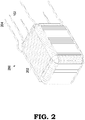
- FIG. 2 illustrates an example implementation of a hollow-core EM coil in accordance with some embodiments.
- a hollow-core EM coil 200 includes three sets of thin metal foil 200 wrapped in three orthogonal directions around a "hollow" plastic core substrate (not visible in FIG. 2 ).
- Each metal foil wrapping is electrically connected to a corresponding set of leads (e.g., leads 204, 205) which in turn are used either to receive an excitation AC signal so as to trigger the generation of a magnetic field in the corresponding plane by the corresponding metal foil wrapping, or to provide a voltage generated by the corresponding metal foil wrapping as a result of a generated EM field.
- leads e.g., leads 204, 205
- the metal foil wrappings 202 extend from end-to-end relative to the external dimensions of the underlying core substrate, and thus this configuration is referred to as an "end-to-end" wrapping.
- the frame of the plastic core substrate could include corner protrusions and the metal foil wrappings are disposed between these corner protrusions. This configuration reduces strain on the metal foil wrappings at the corners, and thus this configuration is referred to herein as a "corner-relief" wrapping.
- FIG. 3 illustrates the fabrication of a hollow-core EM coil 400 in accordance with some embodiments.
- the hollow-core EM coil 400 is fabricated by wrapping a core substrate 402 with three thin metal foil strips 404, 405, 406, in three orthogonal directions 408, 409, 410, respectively.
- the thin metal foil strip 404 is wrapped one or more times around the core substrate 402 in direction 408, which corresponds to the X-Z plane.
- the thin metal foil strip 405 is wrapped one or more times around the core substrate 402 in direction 409, which corresponds to the Y-Z plane.
- the thin metal foil strip 406 is wrapped one or more times around the core substrate 402 in direction 410, which corresponds to the X-Y plane.
- each of the thin metal foil strips 404, 405, 406 is electrically coupled to one or more leads (not shown).
- the thin metal foil strips are composed of a material with a high magnetic permeability, that is, a magnetic permeability higher than iron.
- amorphous metal foils such as Metglas 2714A foil (an amorphous alloy foil available from Metglas, Inc.), nanocrystalline alloy foil available from Metglas, Inc., FINEMET® nanocrystalline alloy ribbon available from Hitachi Metals America, Inc.
- a core substrate 500 is solid (that is, absent of voids or other holes or openings), but composed of a material lighter than ferrite or iron, such as a plastic material.
- a core substrate 700 is formed as a lattice-like framework 702 in that the material of the framework 702 constitutes less than 50 percent of the volume defined by the external dimensions of the core substrate 700. As such, whether composed of ferrite or iron, or of a lighter material, the core substrate 700 is substantially lighter than a solid ferrite or ferrous core of the same volume.
Landscapes
- Engineering & Computer Science (AREA)
- Theoretical Computer Science (AREA)
- General Engineering & Computer Science (AREA)
- Power Engineering (AREA)
- Human Computer Interaction (AREA)
- Physics & Mathematics (AREA)
- General Physics & Mathematics (AREA)
- Computer Hardware Design (AREA)
- Chemical & Material Sciences (AREA)
- Composite Materials (AREA)
- Coils Or Transformers For Communication (AREA)
- Soft Magnetic Materials (AREA)
Description
- Electromagnetic (EM) sensing increasingly is used for tracking purposes in virtual reality (VR) and augmented reality (AR) applications. Tracking systems using EM sensing typically employ an EM coil to generate a strong EM field, and another EM coil to detect a pose or position based on the generated EM field. The transmit-side EM coil generates a three-dimensional (3D) EM field, and the receive-side EM coil outputs one or more voltages, each of the output voltages representing a corresponding positional value with reference to a three degrees of freedom (3DOF) or six degrees of freedom (6DOF) reference frame defined by the 3D EM field. Conventional EM coils employ conductive wiring wrapped around a solid ferrite core. While providing relatively high EM sensitivity, the solid ferrite core is relatively heavy, which in turn increases the weight of the user-held or user-mounted component employing the conventional EM coil, and thus impacting user comfort. Moreover, the heavy solid core of a conventional EM coil results in the conventional EM coil having higher mass. This results in conventional EM coils being susceptible to dislocation due to drop impacts, with such a dislocation shifting the position of the EM coil and thus negatively impacting its accuracy with regard to factory tracking calibration.
WO 2016/141373 A1 relates to systems and methods for augmented reality.EP 1 806 756 B1 relates to miniature coils on core with printed circuit. An EM coil according to the preamble of present claim 1 is known from these prior art documents. - The invention is defined by the independent claims. Preferred embodiments of the invention are defined in the dependent claims.
- The present disclosure may be better understood, and its numerous features and advantages made apparent to those skilled in the art by referencing the accompanying drawings. The use of the same reference symbols in different drawings indicates similar or identical items.
-
FIG. 1 is a block diagram of an augmented reality/virtual reality system having a tracker system employing a hollow-core electromagnetic (EM) coil in accordance with some embodiments. -
FIG. 2 is a diagram illustrating a hollow-core EM coil with edge-to-edge wrappings in accordance with some embodiments. -
FIG. 3 is a diagram illustrating a core substrate and thin foil wrappings of a hollow-core EM coil in accordance with some embodiments. -
FIGs. 4 and 5 are diagrams illustrating example implementations of a core substrate of a hollow-core EM coil in accordance with some embodiments. -
FIGS. 1-5 illustrate systems and techniques for tracking in an augmented reality (AR) or virtual reality (VR) system (referred to collectively and in the alternative as an AR/VR system) using a "hollow-core" electromagnetic (EM) coil. The term "hollow-core" refers to the use of a core substrate that has less mass than the conventional solid ferrite core or solid ferrous core of comparable external dimensions (i.e., of comparable external volume). The core substrate is implemented as a "hollow-core" through the use of materials with a lower density than ferrite or iron, such as plastic materials, through the formation of through-holes or other voids in the body of the core substrate, through the use of a lattice-like hollow-frame structure, or a combination thereof. The core substrate is wrapped in three orthogonal directions with strips of thin metal foil, which may be excited with corresponding alternating current (AC) signals to generate a three-dimensional EM field, or which may be used to generate voltages representative of a position and/or orientation of the hollow-core EM coil within a generated 3D EM field. The thin metal foil is composed of a metal with high magnetic permeability higher than pure iron, such as an amorphous metal foil or nanocrystalline metal foil. The combination of the lightweight nature of the hollow core and the thin and lightweight nature of the thin metal foil while providing high magnetic permeability allows the hollow-core EM coil to provide similar EM field generation or EM field sensing performance of a conventional solid-core EM coil of comparable external dimensions while weighing considerably less. The hollow-core EM coil is lighter than conventional EM coils of comparable dimensions, and thus contributes less to user fatigue and is less susceptible to being dislocated as a result of a drop impact. -
FIG. 1 illustrates an AR/VR system 100 employing an EM-basedtracking system 102 with a hollow-core EM coil in accordance with some embodiments of the present disclosure. The AR/VR system 100 includes a head mounted display (HMD)device 104 for displaying AR or VR content and one or more hand-held controllers, such as hand-heldcontrollers VR system 100, such as tracking a position or orientation (referred to herein collectively or in the alternative as "pose") theHMD device 104, a pose of the hand-heldcontrollers HMD device 104 or other component, and the like, the AR/VR system 100 employs the EM-basedtracking system 102. - The EM-based
tracking system 102 includes an EMfield generation subsystem 110 and an EMfield sensing subsystem 112. The EMfield generation subsystem 110 includes a3D EM coil 114 and a transmission (TX)controller 116. The3D EM coil 114 is configured to generate a 3D EM field in the X, Y, and Z planes, and theTX controller 116 controls the generation of the EM field in each of these planes through control of AC signals S_X, S_Y, and S_Z input to theEM coil 114. The EMfield sensing subsystem 112 includes a3D EM coil 118 and a receive (RX)controller 120. The3D EM coil 118 is configured to sense the generated 3D EM field in each of the X, Y, Z planes and to output a corresponding voltage signal V_X, V_Y, and V_Z to theRX controller 120. TheRX controller 120 then utilizes these three voltage signals to generate three degrees of freedom (3DOF) (position) or six degrees of freedom (6DOF) (position and orientation) data representing the position and/or orientation of theEM coil 118 with respect to the generated EM field. - In embodiments in which the pose of the
HMD device 104 is being tracked, the EMfield sensing subsystem 112 is implemented at theHMD device 104 and the EMfield generation subsystem 110 is implemented external to theHMD device 104. In embodiments wherein the poses of thehandheld controllers HMD device 104, the EMfield generation subsystem 110 is implemented at theHMD device 104 and an instance of the EMfield sensing subsystem 112 is implemented at each of thehandheld controllers HMD device 104 and thehandheld controllers - In at least one embodiment, one or both of the
EM coils
FIG. 2 illustrates an example implementation of a hollow-core EM coil in accordance with some embodiments. InFIG. 2 , a hollow-core EM coil 200 includes three sets ofthin metal foil 200 wrapped in three orthogonal directions around a "hollow" plastic core substrate (not visible inFIG. 2 ). Each metal foil wrapping is electrically connected to a corresponding set of leads (e.g., leads 204, 205) which in turn are used either to receive an excitation AC signal so as to trigger the generation of a magnetic field in the corresponding plane by the corresponding metal foil wrapping, or to provide a voltage generated by the corresponding metal foil wrapping as a result of a generated EM field. In the embodiment ofFIG. 2 , themetal foil wrappings 202 extend from end-to-end relative to the external dimensions of the underlying core substrate, and thus this configuration is referred to as an "end-to-end" wrapping. Alternatively, the frame of the plastic core substrate could include corner protrusions and the metal foil wrappings are disposed between these corner protrusions. This configuration reduces strain on the metal foil wrappings at the corners, and thus this configuration is referred to herein as a "corner-relief" wrapping. -
FIG. 3 illustrates the fabrication of a hollow-core EM coil 400 in accordance with some embodiments. As shown, the hollow-core EM coil 400 is fabricated by wrapping acore substrate 402 with three thinmetal foil strips orthogonal directions metal foil strip 404 is wrapped one or more times around thecore substrate 402 indirection 408, which corresponds to the X-Z plane. The thinmetal foil strip 405 is wrapped one or more times around thecore substrate 402 indirection 409, which corresponds to the Y-Z plane. The thinmetal foil strip 406 is wrapped one or more times around thecore substrate 402 indirection 410, which corresponds to the X-Y plane. Each of the thinmetal foil strips - As explained above, the core substrate of a hollow-core EM coil is "hollow" in that it has less mass than a conventional solid-ferrite or solid-ferrous core of comparable size.
FIGs. 4 and 5 illustrate examples of such hollow-core substrates for use in a hollow-core EM coil in accordance with some embodiments. InFIG. 4 , acore substrate 500 is solid (that is, absent of voids or other holes or openings), but composed of a material lighter than ferrite or iron, such as a plastic material. InFIG. 5 , acore substrate 700 is formed as a lattice-like framework 702 in that the material of theframework 702 constitutes less than 50 percent of the volume defined by the external dimensions of thecore substrate 700. As such, whether composed of ferrite or iron, or of a lighter material, thecore substrate 700 is substantially lighter than a solid ferrite or ferrous core of the same volume. - The use of a lighter hollow-core along with higher magnetic permeability metal foil wrappings permits a hollow-core EM coil to be fabricated with a substantially lower weight while providing almost the same performance as a solid core EM coil of comparable dimensions. To illustrate, the use of a plastic framework for the core substrate as shown in FIG. 7, along with thin metal foil wrappings, permits the construction of an hollow-core EM coil with approximately 50% weight reduction while achieving 95% of the EM sensing performance (for end-to-end wrapping configurations or 75-89% of the EM sensing performance (for corner-relief wrapping configurations) of a conventional solid-ferrite-core EM coil of comparable external dimensions when tested using an excitation signal at 60 kilohertz (kHz) and at a 0.5 meter separation for testing purposes.
- Note that not all of the activities or elements described above in the description of the preferred embodiments are required, that a portion of a specific activity or device may not be required, and that one or more further activities may be performed, or elements included, in addition to those described. Still further, the order in which activities are listed are not necessarily the order in which they are performed. Also, the concepts have been described with reference to specific embodiments. However, one of ordinary skill in the art appreciates that various modifications and changes can be made within the scope of the present disclosure as set forth in the claims below. Accordingly, the specification and figures are to be regarded in an illustrative rather than a restrictive sense.
Claims (15)
- An electromagnetic, EM, coil (114, 118, 200, 400) for position tracking, the EM coil comprising:a core substrate (402, 500, 700) composed of material with a lower density than ferrite or iron, or comprising one or more voids in a body of the core substrate, or being formed as a lattice-like hollow-frame structure to constitute a hollow-core;characterised in that the EM coil further comprises thin metal foil (202, 404, 405, 406) wound around the core substrate along three orthogonal axes, the thin metal foil having a magnetic permeability higher than iron.
- The EM coil of claim 1, wherein:the core substrate is a solid block of material with one or more openings formed therein, orwherein the core substrate is a solid block (500) of plastic.
- The EM coil of claim 1, wherein:
the core substrate is a hollow frame (702) of material. - The EM coil of claims 2 or 3, wherein the material is a ferrous material, or
wherein the material is a ferrite material, or
wherein the material is a plastic material. - The EM coil of claim 1, wherein the thin metal foil comprises a thin amorphous metal foil, or
wherein the thin metal foil comprises a thin nanocrystalline metal foil. - An augmented reality/virtual reality, AR/VR, system (100) comprising:a head mounted display, HMD, device (104);at least one hand-held controller (106, 108); anda tracking system (102) for tracking a position of at least one of the HMD device or the at least one hand-held controller, the tracking system comprising an EM (114, 118, 200, 400) according to present claim 1.
- The AR/VR system of claim 6, wherein:the core substrate is one of: a solid block of material with one or more openings formed therein; and a hollow frame (702) of material,or wherein the core substrate is a solid block (500) of plastic.
- The AR/VR system of claim 7, wherein the material is one of: a ferrous material; a ferrite material; and a plastic material.
- The AR/VR system of any of claims 6 to 8, wherein the thin metal foil comprises one of: a thin amorphous metal foil; and a thin nanocrystalline metal foil.
- A method of tracking a component (106, 108) of an augmented reality/virtual reality, AR/VR, system (100) using an electromagnetic, EM, field, the method comprising:
generating the EM field using an EM coil (114, 200, 400) composed of a core substrate (402, 500, 700) and thin metal foil (202, 404, 405, 406) wound around the core substrate along three orthogonal axes, the core substrate being composed of material with a lower density than ferrite or iron, or comprising one or more voids in a body of the core substrate, or being formed as a lattice-like hollow-frame structure to constitute a hollow-core, and the thin metal foil having a magnetic permeability higher than iron. - The method of claim 10, wherein the core substrate is one of: a solid block of material with one or more openings formed therein; and a hollow frame (702) of material, wherein, as an option, the material is one of: a ferrous material; a ferrite material; and a plastic material.
- The method of claims 10 or 11, wherein the thin metal foil comprises one of: a thin amorphous metal foil; and a thin nanocrystalline metal foil.
- A method of tracking a component (106, 108) of an augmented reality/virtual reality, AR/VR, system (100) using an electromagnetic, EM, field, the method comprising:
sensing the EM field using an EM coil (118, 200, 400) composed of a core substrate (402, 500, 700) and thin metal foil (202, 404, 405, 406) wound around the core substrate along three orthogonal axes, the core substrate being composed of material with a lower density than ferrite or iron, or comprising one or more voids in a body of the core substrate, or being formed as a lattice-like hollow-frame structure to constitute a hollow-core, and the thin metal foil having a magnetic permeability higher than iron. - The method of claim 13, wherein the core substrate is one of: a solid block of material with one or more openings formed therein; and a hollow frame (702) of material, wherein, as an option, the material is one of: a ferrous material; a ferrite material; and a plastic material.
- The method of claims 13 or 14, wherein the thin metal foil comprises one of: a thin amorphous metal foil; and a thin nanocrystalline metal foil.
Applications Claiming Priority (3)
| Application Number | Priority Date | Filing Date | Title |
|---|---|---|---|
| US201862627055P | 2018-02-06 | 2018-02-06 | |
| US16/244,552 US10804027B2 (en) | 2018-02-06 | 2019-01-10 | Hollow core electromagnetic coil |
| PCT/US2019/015610 WO2019156851A1 (en) | 2018-02-06 | 2019-01-29 | Hollow core electromagnetic coil |
Publications (2)
| Publication Number | Publication Date |
|---|---|
| EP3610488A1 EP3610488A1 (en) | 2020-02-19 |
| EP3610488B1 true EP3610488B1 (en) | 2020-08-05 |
Family
ID=67476946
Family Applications (1)
| Application Number | Title | Priority Date | Filing Date |
|---|---|---|---|
| EP19705623.7A Active EP3610488B1 (en) | 2018-02-06 | 2019-01-29 | Hollow core electromagnetic coil |
Country Status (5)
| Country | Link |
|---|---|
| US (1) | US10804027B2 (en) |
| EP (1) | EP3610488B1 (en) |
| CN (1) | CN110520945B (en) |
| TW (1) | TWI750443B (en) |
| WO (1) | WO2019156851A1 (en) |
Families Citing this family (2)
| Publication number | Priority date | Publication date | Assignee | Title |
|---|---|---|---|---|
| DE102020110898A1 (en) * | 2020-04-22 | 2021-10-28 | Neosid Pemetzrieder Gmbh & Co. Kg | One-piece antenna core |
| CN116648926A (en) * | 2020-09-21 | 2023-08-25 | 苹果公司 | Systems with Peripherals with Magnetic Field Tracking |
Family Cites Families (15)
| Publication number | Priority date | Publication date | Assignee | Title |
|---|---|---|---|---|
| JPH02167478A (en) * | 1988-09-22 | 1990-06-27 | Toshiba Corp | Current sensor |
| US5559432A (en) | 1992-02-27 | 1996-09-24 | Logue; Delmar L. | Joystick generating a polar coordinates signal utilizing a rotating magnetic field within a hollow toroid core |
| US8239001B2 (en) * | 2003-10-17 | 2012-08-07 | Medtronic Navigation, Inc. | Method and apparatus for surgical navigation |
| US7447655B2 (en) * | 2000-03-02 | 2008-11-04 | Trading Technologies International, Inc. | System and method for automatic scalping of a tradeable object in an electronic trading environment |
| JP3829761B2 (en) * | 2002-06-04 | 2006-10-04 | 株式会社デンソー | Receiving antenna, portable device |
| US7816915B2 (en) * | 2006-01-06 | 2010-10-19 | Biosense Webster, Inc. | Miniature coils on core with printed circuit |
| CN101577469B (en) * | 2008-05-06 | 2013-02-13 | 鸿富锦精密工业(深圳)有限公司 | Winding axle center |
| WO2012051755A1 (en) * | 2010-10-20 | 2012-04-26 | Astec International Limited | Multi-winding magnetic structures |
| US9427172B2 (en) | 2011-12-30 | 2016-08-30 | Mediguide Ltd. | Roll detection and six degrees of freedom sensor assembly |
| US8994366B2 (en) | 2012-12-12 | 2015-03-31 | Ascension Technology Corporation | Magnetically tracked sensor |
| WO2016094865A1 (en) | 2014-12-11 | 2016-06-16 | St. Jude Medical, Cardiology Division, Inc. | Multi-layer sensor core |
| CN112764536B (en) | 2015-03-05 | 2025-04-01 | 奇跃公司 | Systems and methods for augmented reality |
| WO2017017659A1 (en) | 2015-07-30 | 2017-02-02 | St. Jude Medical International Holding S.A R.L. | Roll-sensing sensor assembly |
| CN106252019B (en) * | 2016-07-09 | 2018-06-19 | 西北工业大学 | A multi-layer three-dimensional magnetic field transmitting coil |
| EP3489972B1 (en) * | 2017-11-27 | 2020-04-15 | Premo, S.A. | Inductor device with light weight configuration |
-
2019
- 2019-01-10 US US16/244,552 patent/US10804027B2/en active Active
- 2019-01-15 TW TW108101457A patent/TWI750443B/en active
- 2019-01-29 CN CN201980001950.7A patent/CN110520945B/en active Active
- 2019-01-29 EP EP19705623.7A patent/EP3610488B1/en active Active
- 2019-01-29 WO PCT/US2019/015610 patent/WO2019156851A1/en not_active Ceased
Non-Patent Citations (1)
| Title |
|---|
| None * |
Also Published As
| Publication number | Publication date |
|---|---|
| WO2019156851A1 (en) | 2019-08-15 |
| TW201941230A (en) | 2019-10-16 |
| US10804027B2 (en) | 2020-10-13 |
| TWI750443B (en) | 2021-12-21 |
| US20190244746A1 (en) | 2019-08-08 |
| CN110520945A (en) | 2019-11-29 |
| EP3610488A1 (en) | 2020-02-19 |
| CN110520945B (en) | 2021-10-08 |
Similar Documents
| Publication | Publication Date | Title |
|---|---|---|
| JP5270482B2 (en) | Position detecting device and sensor unit | |
| EP2830074A2 (en) | Electromagnetic induction sensor, overlay member for electromagnetic induction sensor, and manufacturing method of electromagnetic induction sensor | |
| Murty et al. | The use of magnetostrictive particle actuators for vibration attenuation of flexible beams | |
| US10804027B2 (en) | Hollow core electromagnetic coil | |
| Qian et al. | Theoretical modeling and experimental validation of a torsional piezoelectric vibration energy harvesting system | |
| US20180085786A1 (en) | Multi-core, multi-dimension electromagnet | |
| JP2014153309A5 (en) | ||
| JP6240994B1 (en) | 3D magnetic field detection element and 3D magnetic field detection device | |
| JP3849250B2 (en) | Magnetic 3D tracker | |
| CN103818566B (en) | A kind of modularization making method of three-axis magnetorquer | |
| JP3933635B2 (en) | Relative position / posture measurement system | |
| WO2011074211A1 (en) | Magnetic force sensor | |
| JP2012005308A (en) | Wireless power transmission system | |
| EP3202059B1 (en) | Methods and apparatus for underwater electrical near-field signal system | |
| Farsangi et al. | A novel inertial energy harvester using magnetic shape memory alloy | |
| Ji et al. | Three-dimensional solutions for fan and spine magnetic reconnection in partially ionized plasmas | |
| JP7233856B2 (en) | Position detection sensor | |
| KR101295147B1 (en) | Vibration apparatus and system, method using the same, and recording medium thereof | |
| JP2011191067A (en) | Magnetic field detector and ball game device using this | |
| KR101246606B1 (en) | Vibration generating module using unstable structure, actuator using the same, handheld device, method for generating vibration and recording medium thereof | |
| JP5933358B2 (en) | Electronic key system, electronic key position detection device, and electronic key position detection method | |
| Baranov et al. | Analysis of MEMS fluxgate design for vibration and impact | |
| Jeong et al. | A uniformed DC magnetic generator using ferromagnetic slot cage by geomagnetism distortion cancellation | |
| JP2574193B2 (en) | Electromagnetic field analysis method | |
| CN104122603A (en) | Method for calibrating coil system in three-dimensional array induction logging instrument |
Legal Events
| Date | Code | Title | Description |
|---|---|---|---|
| STAA | Information on the status of an ep patent application or granted ep patent |
Free format text: STATUS: UNKNOWN |
|
| STAA | Information on the status of an ep patent application or granted ep patent |
Free format text: STATUS: THE INTERNATIONAL PUBLICATION HAS BEEN MADE |
|
| PUAI | Public reference made under article 153(3) epc to a published international application that has entered the european phase |
Free format text: ORIGINAL CODE: 0009012 |
|
| STAA | Information on the status of an ep patent application or granted ep patent |
Free format text: STATUS: REQUEST FOR EXAMINATION WAS MADE |
|
| 17P | Request for examination filed |
Effective date: 20191107 |
|
| AK | Designated contracting states |
Kind code of ref document: A1 Designated state(s): AL AT BE BG CH CY CZ DE DK EE ES FI FR GB GR HR HU IE IS IT LI LT LU LV MC MK MT NL NO PL PT RO RS SE SI SK SM TR |
|
| AX | Request for extension of the european patent |
Extension state: BA ME |
|
| GRAP | Despatch of communication of intention to grant a patent |
Free format text: ORIGINAL CODE: EPIDOSNIGR1 |
|
| STAA | Information on the status of an ep patent application or granted ep patent |
Free format text: STATUS: GRANT OF PATENT IS INTENDED |
|
| INTG | Intention to grant announced |
Effective date: 20200306 |
|
| RAP1 | Party data changed (applicant data changed or rights of an application transferred) |
Owner name: GOOGLE LLC |
|
| GRAS | Grant fee paid |
Free format text: ORIGINAL CODE: EPIDOSNIGR3 |
|
| GRAA | (expected) grant |
Free format text: ORIGINAL CODE: 0009210 |
|
| STAA | Information on the status of an ep patent application or granted ep patent |
Free format text: STATUS: THE PATENT HAS BEEN GRANTED |
|
| AK | Designated contracting states |
Kind code of ref document: B1 Designated state(s): AL AT BE BG CH CY CZ DE DK EE ES FI FR GB GR HR HU IE IS IT LI LT LU LV MC MK MT NL NO PL PT RO RS SE SI SK SM TR |
|
| DAV | Request for validation of the european patent (deleted) | ||
| DAX | Request for extension of the european patent (deleted) | ||
| REG | Reference to a national code |
Ref country code: GB Ref legal event code: FG4D |
|
| REG | Reference to a national code |
Ref country code: CH Ref legal event code: EP |
|
| REG | Reference to a national code |
Ref country code: AT Ref legal event code: REF Ref document number: 1299862 Country of ref document: AT Kind code of ref document: T Effective date: 20200815 |
|
| REG | Reference to a national code |
Ref country code: DE Ref legal event code: R096 Ref document number: 602019000410 Country of ref document: DE |
|
| REG | Reference to a national code |
Ref country code: IE Ref legal event code: FG4D |
|
| REG | Reference to a national code |
Ref country code: LT Ref legal event code: MG4D |
|
| REG | Reference to a national code |
Ref country code: NL Ref legal event code: MP Effective date: 20200805 |
|
| REG | Reference to a national code |
Ref country code: AT Ref legal event code: MK05 Ref document number: 1299862 Country of ref document: AT Kind code of ref document: T Effective date: 20200805 |
|
| PG25 | Lapsed in a contracting state [announced via postgrant information from national office to epo] |
Ref country code: SE Free format text: LAPSE BECAUSE OF FAILURE TO SUBMIT A TRANSLATION OF THE DESCRIPTION OR TO PAY THE FEE WITHIN THE PRESCRIBED TIME-LIMIT Effective date: 20200805 Ref country code: HR Free format text: LAPSE BECAUSE OF FAILURE TO SUBMIT A TRANSLATION OF THE DESCRIPTION OR TO PAY THE FEE WITHIN THE PRESCRIBED TIME-LIMIT Effective date: 20200805 Ref country code: FI Free format text: LAPSE BECAUSE OF FAILURE TO SUBMIT A TRANSLATION OF THE DESCRIPTION OR TO PAY THE FEE WITHIN THE PRESCRIBED TIME-LIMIT Effective date: 20200805 Ref country code: ES Free format text: LAPSE BECAUSE OF FAILURE TO SUBMIT A TRANSLATION OF THE DESCRIPTION OR TO PAY THE FEE WITHIN THE PRESCRIBED TIME-LIMIT Effective date: 20200805 Ref country code: BG Free format text: LAPSE BECAUSE OF FAILURE TO SUBMIT A TRANSLATION OF THE DESCRIPTION OR TO PAY THE FEE WITHIN THE PRESCRIBED TIME-LIMIT Effective date: 20201105 Ref country code: PT Free format text: LAPSE BECAUSE OF FAILURE TO SUBMIT A TRANSLATION OF THE DESCRIPTION OR TO PAY THE FEE WITHIN THE PRESCRIBED TIME-LIMIT Effective date: 20201207 Ref country code: GR Free format text: LAPSE BECAUSE OF FAILURE TO SUBMIT A TRANSLATION OF THE DESCRIPTION OR TO PAY THE FEE WITHIN THE PRESCRIBED TIME-LIMIT Effective date: 20201106 Ref country code: AT Free format text: LAPSE BECAUSE OF FAILURE TO SUBMIT A TRANSLATION OF THE DESCRIPTION OR TO PAY THE FEE WITHIN THE PRESCRIBED TIME-LIMIT Effective date: 20200805 Ref country code: LT Free format text: LAPSE BECAUSE OF FAILURE TO SUBMIT A TRANSLATION OF THE DESCRIPTION OR TO PAY THE FEE WITHIN THE PRESCRIBED TIME-LIMIT Effective date: 20200805 Ref country code: NO Free format text: LAPSE BECAUSE OF FAILURE TO SUBMIT A TRANSLATION OF THE DESCRIPTION OR TO PAY THE FEE WITHIN THE PRESCRIBED TIME-LIMIT Effective date: 20201105 |
|
| PG25 | Lapsed in a contracting state [announced via postgrant information from national office to epo] |
Ref country code: LV Free format text: LAPSE BECAUSE OF FAILURE TO SUBMIT A TRANSLATION OF THE DESCRIPTION OR TO PAY THE FEE WITHIN THE PRESCRIBED TIME-LIMIT Effective date: 20200805 Ref country code: NL Free format text: LAPSE BECAUSE OF FAILURE TO SUBMIT A TRANSLATION OF THE DESCRIPTION OR TO PAY THE FEE WITHIN THE PRESCRIBED TIME-LIMIT Effective date: 20200805 Ref country code: PL Free format text: LAPSE BECAUSE OF FAILURE TO SUBMIT A TRANSLATION OF THE DESCRIPTION OR TO PAY THE FEE WITHIN THE PRESCRIBED TIME-LIMIT Effective date: 20200805 Ref country code: RS Free format text: LAPSE BECAUSE OF FAILURE TO SUBMIT A TRANSLATION OF THE DESCRIPTION OR TO PAY THE FEE WITHIN THE PRESCRIBED TIME-LIMIT Effective date: 20200805 Ref country code: IS Free format text: LAPSE BECAUSE OF FAILURE TO SUBMIT A TRANSLATION OF THE DESCRIPTION OR TO PAY THE FEE WITHIN THE PRESCRIBED TIME-LIMIT Effective date: 20201205 |
|
| PG25 | Lapsed in a contracting state [announced via postgrant information from national office to epo] |
Ref country code: EE Free format text: LAPSE BECAUSE OF FAILURE TO SUBMIT A TRANSLATION OF THE DESCRIPTION OR TO PAY THE FEE WITHIN THE PRESCRIBED TIME-LIMIT Effective date: 20200805 Ref country code: RO Free format text: LAPSE BECAUSE OF FAILURE TO SUBMIT A TRANSLATION OF THE DESCRIPTION OR TO PAY THE FEE WITHIN THE PRESCRIBED TIME-LIMIT Effective date: 20200805 Ref country code: CZ Free format text: LAPSE BECAUSE OF FAILURE TO SUBMIT A TRANSLATION OF THE DESCRIPTION OR TO PAY THE FEE WITHIN THE PRESCRIBED TIME-LIMIT Effective date: 20200805 Ref country code: DK Free format text: LAPSE BECAUSE OF FAILURE TO SUBMIT A TRANSLATION OF THE DESCRIPTION OR TO PAY THE FEE WITHIN THE PRESCRIBED TIME-LIMIT Effective date: 20200805 Ref country code: SM Free format text: LAPSE BECAUSE OF FAILURE TO SUBMIT A TRANSLATION OF THE DESCRIPTION OR TO PAY THE FEE WITHIN THE PRESCRIBED TIME-LIMIT Effective date: 20200805 |
|
| REG | Reference to a national code |
Ref country code: DE Ref legal event code: R097 Ref document number: 602019000410 Country of ref document: DE |
|
| PG25 | Lapsed in a contracting state [announced via postgrant information from national office to epo] |
Ref country code: AL Free format text: LAPSE BECAUSE OF FAILURE TO SUBMIT A TRANSLATION OF THE DESCRIPTION OR TO PAY THE FEE WITHIN THE PRESCRIBED TIME-LIMIT Effective date: 20200805 |
|
| PLBE | No opposition filed within time limit |
Free format text: ORIGINAL CODE: 0009261 |
|
| STAA | Information on the status of an ep patent application or granted ep patent |
Free format text: STATUS: NO OPPOSITION FILED WITHIN TIME LIMIT |
|
| PG25 | Lapsed in a contracting state [announced via postgrant information from national office to epo] |
Ref country code: SK Free format text: LAPSE BECAUSE OF FAILURE TO SUBMIT A TRANSLATION OF THE DESCRIPTION OR TO PAY THE FEE WITHIN THE PRESCRIBED TIME-LIMIT Effective date: 20200805 |
|
| 26N | No opposition filed |
Effective date: 20210507 |
|
| PG25 | Lapsed in a contracting state [announced via postgrant information from national office to epo] |
Ref country code: IT Free format text: LAPSE BECAUSE OF FAILURE TO SUBMIT A TRANSLATION OF THE DESCRIPTION OR TO PAY THE FEE WITHIN THE PRESCRIBED TIME-LIMIT Effective date: 20200805 |
|
| PG25 | Lapsed in a contracting state [announced via postgrant information from national office to epo] |
Ref country code: MC Free format text: LAPSE BECAUSE OF FAILURE TO SUBMIT A TRANSLATION OF THE DESCRIPTION OR TO PAY THE FEE WITHIN THE PRESCRIBED TIME-LIMIT Effective date: 20200805 |
|
| PG25 | Lapsed in a contracting state [announced via postgrant information from national office to epo] |
Ref country code: LU Free format text: LAPSE BECAUSE OF NON-PAYMENT OF DUE FEES Effective date: 20210129 |
|
| REG | Reference to a national code |
Ref country code: BE Ref legal event code: MM Effective date: 20210131 |
|
| PG25 | Lapsed in a contracting state [announced via postgrant information from national office to epo] |
Ref country code: FR Free format text: LAPSE BECAUSE OF NON-PAYMENT OF DUE FEES Effective date: 20210131 |
|
| PG25 | Lapsed in a contracting state [announced via postgrant information from national office to epo] |
Ref country code: IE Free format text: LAPSE BECAUSE OF NON-PAYMENT OF DUE FEES Effective date: 20210129 |
|
| PG25 | Lapsed in a contracting state [announced via postgrant information from national office to epo] |
Ref country code: BE Free format text: LAPSE BECAUSE OF NON-PAYMENT OF DUE FEES Effective date: 20210131 |
|
| REG | Reference to a national code |
Ref country code: CH Ref legal event code: PL |
|
| PG25 | Lapsed in a contracting state [announced via postgrant information from national office to epo] |
Ref country code: LI Free format text: LAPSE BECAUSE OF NON-PAYMENT OF DUE FEES Effective date: 20220131 Ref country code: CH Free format text: LAPSE BECAUSE OF NON-PAYMENT OF DUE FEES Effective date: 20220131 |
|
| P01 | Opt-out of the competence of the unified patent court (upc) registered |
Effective date: 20230506 |
|
| PG25 | Lapsed in a contracting state [announced via postgrant information from national office to epo] |
Ref country code: CY Free format text: LAPSE BECAUSE OF FAILURE TO SUBMIT A TRANSLATION OF THE DESCRIPTION OR TO PAY THE FEE WITHIN THE PRESCRIBED TIME-LIMIT Effective date: 20200805 |
|
| PG25 | Lapsed in a contracting state [announced via postgrant information from national office to epo] |
Ref country code: HU Free format text: LAPSE BECAUSE OF FAILURE TO SUBMIT A TRANSLATION OF THE DESCRIPTION OR TO PAY THE FEE WITHIN THE PRESCRIBED TIME-LIMIT; INVALID AB INITIO Effective date: 20190129 |
|
| PG25 | Lapsed in a contracting state [announced via postgrant information from national office to epo] |
Ref country code: SI Free format text: LAPSE BECAUSE OF FAILURE TO SUBMIT A TRANSLATION OF THE DESCRIPTION OR TO PAY THE FEE WITHIN THE PRESCRIBED TIME-LIMIT Effective date: 20200805 |
|
| PG25 | Lapsed in a contracting state [announced via postgrant information from national office to epo] |
Ref country code: MK Free format text: LAPSE BECAUSE OF FAILURE TO SUBMIT A TRANSLATION OF THE DESCRIPTION OR TO PAY THE FEE WITHIN THE PRESCRIBED TIME-LIMIT Effective date: 20200805 |
|
| PG25 | Lapsed in a contracting state [announced via postgrant information from national office to epo] |
Ref country code: TR Free format text: LAPSE BECAUSE OF FAILURE TO SUBMIT A TRANSLATION OF THE DESCRIPTION OR TO PAY THE FEE WITHIN THE PRESCRIBED TIME-LIMIT Effective date: 20200805 |
|
| PG25 | Lapsed in a contracting state [announced via postgrant information from national office to epo] |
Ref country code: MT Free format text: LAPSE BECAUSE OF FAILURE TO SUBMIT A TRANSLATION OF THE DESCRIPTION OR TO PAY THE FEE WITHIN THE PRESCRIBED TIME-LIMIT Effective date: 20200805 |
|
| PGFP | Annual fee paid to national office [announced via postgrant information from national office to epo] |
Ref country code: GB Payment date: 20260127 Year of fee payment: 8 |
|
| PGFP | Annual fee paid to national office [announced via postgrant information from national office to epo] |
Ref country code: DE Payment date: 20260128 Year of fee payment: 8 |