EP3609800B1 - Anti-clog cap - Google Patents
Anti-clog cap Download PDFInfo
- Publication number
- EP3609800B1 EP3609800B1 EP18783896.6A EP18783896A EP3609800B1 EP 3609800 B1 EP3609800 B1 EP 3609800B1 EP 18783896 A EP18783896 A EP 18783896A EP 3609800 B1 EP3609800 B1 EP 3609800B1
- Authority
- EP
- European Patent Office
- Prior art keywords
- nozzle
- cap
- tip
- glue
- section
- Prior art date
- Legal status (The legal status is an assumption and is not a legal conclusion. Google has not performed a legal analysis and makes no representation as to the accuracy of the status listed.)
- Active
Links
Images





Classifications
-
- B—PERFORMING OPERATIONS; TRANSPORTING
- B65—CONVEYING; PACKING; STORING; HANDLING THIN OR FILAMENTARY MATERIAL
- B65D—CONTAINERS FOR STORAGE OR TRANSPORT OF ARTICLES OR MATERIALS, e.g. BAGS, BARRELS, BOTTLES, BOXES, CANS, CARTONS, CRATES, DRUMS, JARS, TANKS, HOPPERS, FORWARDING CONTAINERS; ACCESSORIES, CLOSURES, OR FITTINGS THEREFOR; PACKAGING ELEMENTS; PACKAGES
- B65D47/00—Closures with filling and discharging, or with discharging, devices
- B65D47/04—Closures with discharging devices other than pumps
- B65D47/20—Closures with discharging devices other than pumps comprising hand-operated members for controlling discharge
- B65D47/24—Closures with discharging devices other than pumps comprising hand-operated members for controlling discharge with poppet valves or lift valves, i.e. valves opening or closing a passageway by a relative motion substantially perpendicular to the plane of the seat
- B65D47/241—Closures with discharging devices other than pumps comprising hand-operated members for controlling discharge with poppet valves or lift valves, i.e. valves opening or closing a passageway by a relative motion substantially perpendicular to the plane of the seat the valve being opened or closed by actuating a cap-like element
- B65D47/242—Closures with discharging devices other than pumps comprising hand-operated members for controlling discharge with poppet valves or lift valves, i.e. valves opening or closing a passageway by a relative motion substantially perpendicular to the plane of the seat the valve being opened or closed by actuating a cap-like element moving helically
-
- B—PERFORMING OPERATIONS; TRANSPORTING
- B65—CONVEYING; PACKING; STORING; HANDLING THIN OR FILAMENTARY MATERIAL
- B65D—CONTAINERS FOR STORAGE OR TRANSPORT OF ARTICLES OR MATERIALS, e.g. BAGS, BARRELS, BOTTLES, BOXES, CANS, CARTONS, CRATES, DRUMS, JARS, TANKS, HOPPERS, FORWARDING CONTAINERS; ACCESSORIES, CLOSURES, OR FITTINGS THEREFOR; PACKAGING ELEMENTS; PACKAGES
- B65D47/00—Closures with filling and discharging, or with discharging, devices
- B65D47/04—Closures with discharging devices other than pumps
- B65D47/20—Closures with discharging devices other than pumps comprising hand-operated members for controlling discharge
- B65D47/24—Closures with discharging devices other than pumps comprising hand-operated members for controlling discharge with poppet valves or lift valves, i.e. valves opening or closing a passageway by a relative motion substantially perpendicular to the plane of the seat
- B65D47/241—Closures with discharging devices other than pumps comprising hand-operated members for controlling discharge with poppet valves or lift valves, i.e. valves opening or closing a passageway by a relative motion substantially perpendicular to the plane of the seat the valve being opened or closed by actuating a cap-like element
- B65D47/243—Closures with discharging devices other than pumps comprising hand-operated members for controlling discharge with poppet valves or lift valves, i.e. valves opening or closing a passageway by a relative motion substantially perpendicular to the plane of the seat the valve being opened or closed by actuating a cap-like element moving linearly, i.e. without rotational motion
-
- B—PERFORMING OPERATIONS; TRANSPORTING
- B65—CONVEYING; PACKING; STORING; HANDLING THIN OR FILAMENTARY MATERIAL
- B65D—CONTAINERS FOR STORAGE OR TRANSPORT OF ARTICLES OR MATERIALS, e.g. BAGS, BARRELS, BOTTLES, BOXES, CANS, CARTONS, CRATES, DRUMS, JARS, TANKS, HOPPERS, FORWARDING CONTAINERS; ACCESSORIES, CLOSURES, OR FITTINGS THEREFOR; PACKAGING ELEMENTS; PACKAGES
- B65D2203/00—Decoration means, markings, information elements, contents indicators
- B65D2203/12—Audible, olfactory or visual signalling means
-
- B—PERFORMING OPERATIONS; TRANSPORTING
- B65—CONVEYING; PACKING; STORING; HANDLING THIN OR FILAMENTARY MATERIAL
- B65D—CONTAINERS FOR STORAGE OR TRANSPORT OF ARTICLES OR MATERIALS, e.g. BAGS, BARRELS, BOTTLES, BOXES, CANS, CARTONS, CRATES, DRUMS, JARS, TANKS, HOPPERS, FORWARDING CONTAINERS; ACCESSORIES, CLOSURES, OR FITTINGS THEREFOR; PACKAGING ELEMENTS; PACKAGES
- B65D2251/00—Details relating to container closures
- B65D2251/01—Details relating to container closures making a sound upon actuation
-
- B—PERFORMING OPERATIONS; TRANSPORTING
- B65—CONVEYING; PACKING; STORING; HANDLING THIN OR FILAMENTARY MATERIAL
- B65D—CONTAINERS FOR STORAGE OR TRANSPORT OF ARTICLES OR MATERIALS, e.g. BAGS, BARRELS, BOTTLES, BOXES, CANS, CARTONS, CRATES, DRUMS, JARS, TANKS, HOPPERS, FORWARDING CONTAINERS; ACCESSORIES, CLOSURES, OR FITTINGS THEREFOR; PACKAGING ELEMENTS; PACKAGES
- B65D2401/00—Tamper-indicating means
- B65D2401/15—Tearable part of the closure
-
- B—PERFORMING OPERATIONS; TRANSPORTING
- B65—CONVEYING; PACKING; STORING; HANDLING THIN OR FILAMENTARY MATERIAL
- B65D—CONTAINERS FOR STORAGE OR TRANSPORT OF ARTICLES OR MATERIALS, e.g. BAGS, BARRELS, BOTTLES, BOXES, CANS, CARTONS, CRATES, DRUMS, JARS, TANKS, HOPPERS, FORWARDING CONTAINERS; ACCESSORIES, CLOSURES, OR FITTINGS THEREFOR; PACKAGING ELEMENTS; PACKAGES
- B65D47/00—Closures with filling and discharging, or with discharging, devices
- B65D47/04—Closures with discharging devices other than pumps
- B65D47/06—Closures with discharging devices other than pumps with pouring spouts or tubes; with discharge nozzles or passages
-
- B—PERFORMING OPERATIONS; TRANSPORTING
- B65—CONVEYING; PACKING; STORING; HANDLING THIN OR FILAMENTARY MATERIAL
- B65D—CONTAINERS FOR STORAGE OR TRANSPORT OF ARTICLES OR MATERIALS, e.g. BAGS, BARRELS, BOTTLES, BOXES, CANS, CARTONS, CRATES, DRUMS, JARS, TANKS, HOPPERS, FORWARDING CONTAINERS; ACCESSORIES, CLOSURES, OR FITTINGS THEREFOR; PACKAGING ELEMENTS; PACKAGES
- B65D47/00—Closures with filling and discharging, or with discharging, devices
- B65D47/04—Closures with discharging devices other than pumps
- B65D47/20—Closures with discharging devices other than pumps comprising hand-operated members for controlling discharge
- B65D47/2018—Closures with discharging devices other than pumps comprising hand-operated members for controlling discharge comprising a valve or like element which is opened or closed by deformation of the container or closure
- B65D47/2031—Closures with discharging devices other than pumps comprising hand-operated members for controlling discharge comprising a valve or like element which is opened or closed by deformation of the container or closure the element being formed by a slit, narrow opening or constrictable spout, the size of the outlet passage being able to be varied by increasing or decreasing the pressure
-
- B—PERFORMING OPERATIONS; TRANSPORTING
- B65—CONVEYING; PACKING; STORING; HANDLING THIN OR FILAMENTARY MATERIAL
- B65D—CONTAINERS FOR STORAGE OR TRANSPORT OF ARTICLES OR MATERIALS, e.g. BAGS, BARRELS, BOTTLES, BOXES, CANS, CARTONS, CRATES, DRUMS, JARS, TANKS, HOPPERS, FORWARDING CONTAINERS; ACCESSORIES, CLOSURES, OR FITTINGS THEREFOR; PACKAGING ELEMENTS; PACKAGES
- B65D51/00—Closures not otherwise provided for
- B65D51/18—Arrangements of closures with protective outer cap-like covers or of two or more co-operating closures
Definitions
- This disclosure generally relates to containers for consumer pourable glues, and more particularly relates to a cap design for preventing clogging of the cap.
- a primary contributor to clogging is the configuration of the cap.
- the configuration of the cap can impact the ability of the glue to flow back into the bottle after use, resulting in the glue stalling on the cap, and components of the cap, where it can dry when exposed to air before making its way back into the bottle. Over time, this glue builds up, eventually leading to clogging. This type of buildup is especially prevalent when the glue forms a "soap bubble" effect, bridging between the internal geometries or surfaces of the cap via surface tension. This soap bubble prevents the glue from freely flowing back into the bottle after use, exposing the soap bubble glue to air within the cap, preventing proper closure of the cap, and increasing the volume of glue that may dry on the internal components of the cap after each use.
- the cap may further comprise a status indicator, which indicates whether the nozzle is in the open or closed position or indicates a transition between the open and closed positions.
- the status indicator may be a visual indicator.
- the visual indicator may comprise a visualization element disposed on the nozzle and the second mounting end of the body may comprise a recess.
- the visualization element may be configured such that when the nozzle is in the open position, the visualization element is visible, and when the nozzle is in the closed position, the visualization element is positioned in the recess, hiding the visualization element from view.
- the visualization element may be a band of color different than the color of the rest of the nozzle.
- the status indicator may be an audible and/or tactile indicator.
- the status indicator may comprise a first interference element disposed on the nozzle and a second interference element disposed on the body.
- the first interference element and the second interference element may be configured to provide audible and/or tactile feedback to the user when the nozzle is rotated from the open position to the closed position.
- the nozzle may be bullet shaped, having a generally cylindrical midsection and a generally conical tip.
- the tip orifice may be cylindrical.
- the nozzle may have a generally conical shape.
- the support rib may be dimensioned to approximately follow the interior profile of the nozzle along at least one plane.
- the anti-clog cap described herein advantageously accommodates various pourable glues having a range of viscosities as well as various use applications.
- the present disclosure includes non-limiting embodiments of anti-clog caps for pourable glue bottles. The embodiments are described in detail herein to enable one of ordinary skill in the art to practice the anti-clog caps, although it is to be understood that other embodiments may be utilized and that logical changes may be made without departing from the scope of the disclosure. Reference is made herein to the accompanying drawings illustrating some embodiments of the disclosure, in which use of the same reference numerals indicates similar or identical items. Throughout the disclosure, depending on the context, singular and plural terminology may be used interchangeably.
- FIG. 1 illustrates a pourable glue container 100 in accordance with one or more embodiments of the disclosure.
- the glue container 100 includes a bottle 110 and an anti-clog cap 120, as described below.
- the anti-clog cap 120 includes a body 205 and a nozzle 210.
- FIGS. 2B and 2C provide cross-sectional views of the anti-clog cap 120, offset 90 degrees from one another.
- the nozzle 210 may include a mating end 215 that is adapted for attachment to the body 205, and a distal end 220 that includes a tip orifice 225.
- the body 205 includes a mounting section 230 that includes a first mounting end 235 and a second mounting end 240, and is adapted for mounting the body 205 to the bottle 110 of a glue container.
- the first mounting end 235 may include male threads 237 for engaging with corresponding male threads included on the glue bottle 110 and allowing for the cooperative engagement between the body 205 and the glue bottle 110 which allows for rotational and axial displacement of the body 205 and secures the body 205 to the glue bottle 110.
- female-male threaded connections may be used as described herein, it should be understood that any suitable connection mechanisms for connecting elements of the containers (e.g., for connecting the nozzle and the body or the body and the bottle) may be used.
- the body 205 includes a dispensing section 245. As shown, the dispensing section 245 extends distally from the second mounting end 240 and includes, an inlet end 250, adjacent to the second mounting end 240, an outlet end 255, opposite the inlet end 250, and a central lumen 260, extending between the inlet end 250 and the outlet end 255 to allow glue to pass through the body 205 of the anti-clog cap 120 when in use. As used herein, the terms “distally” and “proximally” refer to the position of components of the cap relative to the bottle of the container.
- the body 205 also includes a tip section 270.
- the tip section 270 extends distally from the outlet end 255 and include a support rib 275 that protrudes distally from the outlet end 255 of the dispensing section 245, and a tip plug 280 that protrudes distally from the support rib 275 and in axial alignment with the tip orifice 225. Further details regarding the configuration of the nozzle 210 and the body 205, as well as the movement of the nozzle 210 relative to the body 205, are provided below.
- the tip section 270 is dimensioned to facilitate the free flow of glue through the anti-clog cap 120.
- the geometry of the cap for pourable glue bottles may impact not only the characteristics of the glue when poured, but also the propensity of the cap to clog over time.
- the container When the glue container is in use, the container is inverted, either fully or partially, allowing gravity and/or pressure applied by the user to flow glue from the bottle, through the cap, and onto a work surface. When not dispensing, the container may be returned to an upright position, such that gravity causes glue inside the cap 120 to flow back towards the bottle.
- the cohesive forces between the glue molecules allow the glue to create a "film” capable of spanning open areas, while the adhesive forces between the glue and the components of the cap allow the glue to attach to adjacent components within the cap itself.
- This combination of cohesive and adhesive forces allow the glue to span open areas, creating a "film” or “soap bubble” effect that can dry and build up over time, leading to clogging.
- the generally small dispensing diameter will result in the buildup of glue in the orifice when the surface tension of the glue is sufficient to withstand the gravitational forces acting on the glue, urging it to flow back into the bottle.
- the glue flows back proximally over the internal elements of the cap, there are additional opportunities for the glue to adhere and create a film bridging the open spaces within the cap as it flows back into the bottle.
- the anti-clog cap 120 may include a tip plug 280 that is integrated into the body 205 of the anti-clog cap 120.
- the nozzle 210 is rotatable between a closed position and an open position, such that, when the nozzle 210 is in the closed position, the tip plug 280 extends into the tip orifice 225, substantially preventing the flow of glue through the tip orifice 225, and when the nozzle 210 is in the open position, the tip plug 280 is positioned outside of and proximal to the tip orifice 225 (as shown in FIGS. 2B and 2C ), to allow the free flow of glue through the tip orifice 225.
- By extending the tip plug 280 into the tip orifice 225 when closing the cap 120 some or all of the film covering the tip orifice 225 is displaced.
- the interstitial spaces must be large enough that the cohesive forces in the glue are insufficient to create a film bridging the glue pathway.
- the free flow of glue back into the bottle is maintained, meaning the glue cannot span the open space between the support rib 275 or the central lumen 260, preventing the buildup of dried glue across the glue pathways.
- a large tolerance for variations in adhesive viscosity is achieved.
- the tip plug 605 may be longer than the overall length of the cap body and nozzle.
- the tip plug may extend proximally beyond the mounting section 230, and the fixation elements 610 may extend proximally from the body 205 to attach at the proximal end of the tip plug 605.
- the cap may include a plug assembly 600 with tip plug 605 (e.g., a solid cylindrical tip plug) and one or more fixation elements 610 positioning the cylindrical tip plug 280 coaxially with the longitudinal axis of the cap 120 and the tip orifice 225 and attaching to the body 205 at a position proximal to the outlet end 255.
- tip plug 605 e.g., a solid cylindrical tip plug
- fixation elements 610 positioning the cylindrical tip plug 280 coaxially with the longitudinal axis of the cap 120 and the tip orifice 225 and attaching to the body 205 at a position proximal to the outlet end 255.
Landscapes
- Engineering & Computer Science (AREA)
- Mechanical Engineering (AREA)
- Closures For Containers (AREA)
Description
- This disclosure generally relates to containers for consumer pourable glues, and more particularly relates to a cap design for preventing clogging of the cap.
- Currently, pourable glue containers are susceptible to clogging after use. After dispensing glue initially, residual glue that does not return to the glue container body dries, building up over time, and eventually clogging the cap. A clogged cap is undesirable because it often leads to reduced or obstructed flow and increased force required to open the cap. Once clogged, users may throw away the bottle despite any remaining volume of usable glue inside the bottle, or they may try to open the clogged hole with a foreign object such as a pin or paperclip or by soaking the bottle in warm water. In some instances, caps are provided with removable pins to help alleviate these issues; however, removable components are cumbersome, can allow glue to leak from the cap even with proper use, and are subject to being lost. In other instances, caps have been designed with integrated pins that extend through the outlet hole when in the closed position, to prevent glue from drying in the hole after use; however, such integrated pins may be susceptible to clogging.
- A primary contributor to clogging is the configuration of the cap. The configuration of the cap can impact the ability of the glue to flow back into the bottle after use, resulting in the glue stalling on the cap, and components of the cap, where it can dry when exposed to air before making its way back into the bottle. Over time, this glue builds up, eventually leading to clogging. This type of buildup is especially prevalent when the glue forms a "soap bubble" effect, bridging between the internal geometries or surfaces of the cap via surface tension. This soap bubble prevents the glue from freely flowing back into the bottle after use, exposing the soap bubble glue to air within the cap, preventing proper closure of the cap, and increasing the volume of glue that may dry on the internal components of the cap after each use.
- Another primary contributor to clogging is improper closure of the cap. Commonly, caps are inadvertently left open because the cap itself provides no easy indication for users, especially children, that the cap is closed completely.
- Accordingly, a need exists for pourable glue containers and caps that overcome one or more of these disadvantages.
-
US 6,338,425 B1 relates to a dispensing closure for a product container including a base positioned on the container and a cap operable on the base between a closed and an open position. A plug is supported by a support spider formed of spaced radially extending spokes which minimally restrict the flow of discharging product annularly about the plug when the cap is in its open position.US 3,598,285 A discloses an anti-clog cap according to the preamble of claim 1. - In one aspect, an anti-clog cap for a glue bottle is provided, including a body that has a mounting section, a dispensing section, and a tip section. The mounting section of the body has an end adapted for attaching to the glue bottle. The dispensing section extends from a second end of the mounting section and has an inlet end and an outlet end. A central lumen extends from the inlet end and the outlet end of the dispensing section. The body of the anti-clog cap includes a tip section that extends from the outlet end of the dispensing section. The tip section includes a support rib that protrudes from the outlet end of the dispensing section. The tip section also includes a tip plug that protrudes from the support rib. The support rib is an arcuate rib extending distally from a first position on the outlet end of the dispensing section, passing through a longitudinal centerline of the central lumen, and terminating at a second position on the outlet end of the dispensing section. The arcuate rib is dimensioned to follow the interior profile of the nozzle along at least one plane, maximizing the area bounded by the support rib and the outlet end of the dispensing section. The anti-clog cap has a nozzle that has a mating end to attach to the body of the anti-clog cap. The nozzle includes a tip orifice in alignment with the tip plug. The tip section of the body is configured to allow for the free flow of glue through the cap. The nozzle is configured to rotate between an open and a closed position. When the nozzle is in the closed position, the tip plug extends through the tip orifice in the nozzle and prevents the flow of glue through the orifice. When the nozzle is in the open position, the tip plug is positioned outside to the tip orifice to facilitate the free flow of glue through the tip orifice.
- The cap may further comprise a status indicator, which indicates whether the nozzle is in the open or closed position or indicates a transition between the open and closed positions. The status indicator may be a visual indicator. The visual indicator may comprise a visualization element disposed on the nozzle and the second mounting end of the body may comprise a recess. The visualization element may be configured such that when the nozzle is in the open position, the visualization element is visible, and when the nozzle is in the closed position, the visualization element is positioned in the recess, hiding the visualization element from view. The visualization element may be a band of color different than the color of the rest of the nozzle. The status indicator may be an audible and/or tactile indicator. The status indicator may comprise a first interference element disposed on the nozzle and a second interference element disposed on the body. The first interference element and the second interference element may be configured to provide audible and/or tactile feedback to the user when the nozzle is rotated from the open position to the closed position.
- The nozzle may be bullet shaped, having a generally cylindrical midsection and a generally conical tip. The tip orifice may be cylindrical. The nozzle may have a generally conical shape. The support rib may be dimensioned to approximately follow the interior profile of the nozzle along at least one plane.
- The radius of the central lumen may be at least 4.11 mm. The support rib may be dimensioned to allow substantially all of the glue to flow proximally through the body towards the glue bottle when the glue bottle is in an upright or semi-upright position.
-
-
FIG. 1 is a perspective view of one embodiment of an anti-clog cap and a glue bottle. -
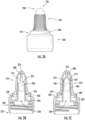
FIG. 2A is a front view of one embodiment of an anti-clog cap. -
FIG. 2B is a cross-sectional side view of the anti-clog cap ofFIG. 2A . -
FIG. 2C is a cross-sectional front view of the anti-clog cap ofFIG. 2A . -
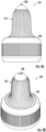
FIG. 3A is a top perspective view of one embodiment of an anti-clog cap. -
FIG. 3B is a front view of the anti-clog cap ofFIG. 3A . -
FIG. 4A is a front view of one embodiment of an anti-clog cap in a closed position. -
FIG. 4B is a top perspective view of the closed position anti-clog cap ofFIG. 4A . -
FIG. 5A is a front perspective view of the anti-clog cap ofFIG. 4A in an open position. -
FIG. 5B is a top perspective view of the anti-clog cap ofFIG. 4A in an open position. -
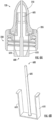
FIG. 6A is a cross-sectional front view of an anti-clog cap not forming part of the invention. -
FIG. 6B is a perspective view of a plug assembly not forming part of the invention. -
FIG. 7A is a front view of an anti-clog cap not forming part of the invention. -
FIG. 7B is a cross-sectional side view of the anti-clog cap ofFIG. 7A . -
FIG. 7C is a cross-sectional front view of the anti-clog cap ofFIG. 7A . -
FIG. 8A is a front view of one embodiment of an anti-clog cap in a closed position. -
FIG. 8B is a side view of the anti-clog cap ofFIG. 8A in a closed position. -
FIG. 8C is a top perspective view of the anti-clog cap ofFIG. 8A in a closed position. -
FIG. 9 is a top perspective view of the anti-clog cap ofFIG. 8A in an open position. - The anti-clog cap described herein advantageously accommodates various pourable glues having a range of viscosities as well as various use applications. The present disclosure includes non-limiting embodiments of anti-clog caps for pourable glue bottles. The embodiments are described in detail herein to enable one of ordinary skill in the art to practice the anti-clog caps, although it is to be understood that other embodiments may be utilized and that logical changes may be made without departing from the scope of the disclosure. Reference is made herein to the accompanying drawings illustrating some embodiments of the disclosure, in which use of the same reference numerals indicates similar or identical items. Throughout the disclosure, depending on the context, singular and plural terminology may be used interchangeably.
- The meanings of the terms used herein will be apparent to one of ordinary skill in the art or will become apparent to one of ordinary skill in the art upon review of the detailed description when taken in conjunction with the several drawings and the appended claims.
-
FIG. 1 illustrates apourable glue container 100 in accordance with one or more embodiments of the disclosure. Theglue container 100 includes abottle 110 and ananti-clog cap 120, as described below. In particular, as shown inFIGS. 2A-2C , theanti-clog cap 120 includes abody 205 and anozzle 210. Notably,FIGS. 2B and 2C provide cross-sectional views of theanti-clog cap 120, offset 90 degrees from one another. Thenozzle 210 may include amating end 215 that is adapted for attachment to thebody 205, and adistal end 220 that includes atip orifice 225. In one example embodiment, themating end 215 may include female threads 227 for engaging with correspondingmale threads 229 included on thebody 205 and allowing for the cooperative engagement between thenozzle 210 and thebody 205 which allows for rotational and axial displacement of thenozzle 210 and secures thenozzle 210 to thebody 205. - The
body 205 includes a mountingsection 230 that includes a first mountingend 235 and a second mountingend 240, and is adapted for mounting thebody 205 to thebottle 110 of a glue container. The first mountingend 235 may include male threads 237 for engaging with corresponding male threads included on theglue bottle 110 and allowing for the cooperative engagement between thebody 205 and theglue bottle 110 which allows for rotational and axial displacement of thebody 205 and secures thebody 205 to theglue bottle 110. While female-male threaded connections may be used as described herein, it should be understood that any suitable connection mechanisms for connecting elements of the containers (e.g., for connecting the nozzle and the body or the body and the bottle) may be used. - The
body 205 includes adispensing section 245. As shown, thedispensing section 245 extends distally from the second mountingend 240 and includes, aninlet end 250, adjacent to the second mountingend 240, anoutlet end 255, opposite theinlet end 250, and acentral lumen 260, extending between theinlet end 250 and theoutlet end 255 to allow glue to pass through thebody 205 of theanti-clog cap 120 when in use. As used herein, the terms "distally" and "proximally" refer to the position of components of the cap relative to the bottle of the container. The body 205also includes atip section 270. Thetip section 270 extends distally from theoutlet end 255 and include asupport rib 275 that protrudes distally from theoutlet end 255 of thedispensing section 245, and atip plug 280 that protrudes distally from thesupport rib 275 and in axial alignment with thetip orifice 225. Further details regarding the configuration of thenozzle 210 and thebody 205, as well as the movement of thenozzle 210 relative to thebody 205, are provided below. - The
tip section 270 is dimensioned to facilitate the free flow of glue through theanti-clog cap 120. As described above, the geometry of the cap for pourable glue bottles may impact not only the characteristics of the glue when poured, but also the propensity of the cap to clog over time. When the glue container is in use, the container is inverted, either fully or partially, allowing gravity and/or pressure applied by the user to flow glue from the bottle, through the cap, and onto a work surface. When not dispensing, the container may be returned to an upright position, such that gravity causes glue inside thecap 120 to flow back towards the bottle. Over a sufficiently small open area or distance, the cohesive forces between the glue molecules allow the glue to create a "film" capable of spanning open areas, while the adhesive forces between the glue and the components of the cap allow the glue to attach to adjacent components within the cap itself. This combination of cohesive and adhesive forces allow the glue to span open areas, creating a "film" or "soap bubble" effect that can dry and build up over time, leading to clogging. Without any type of closure or cap to seal the tip orifice of the nozzle, the generally small dispensing diameter will result in the buildup of glue in the orifice when the surface tension of the glue is sufficient to withstand the gravitational forces acting on the glue, urging it to flow back into the bottle. Similarly, as the glue flows back proximally over the internal elements of the cap, there are additional opportunities for the glue to adhere and create a film bridging the open spaces within the cap as it flows back into the bottle. - When glue creates a film over the
tip orifice 225 of thenozzle 210, it can dry in place, clogging the cap. Accordingly, theanti-clog cap 120 may include atip plug 280 that is integrated into thebody 205 of theanti-clog cap 120. Thenozzle 210 is rotatable between a closed position and an open position, such that, when thenozzle 210 is in the closed position, thetip plug 280 extends into thetip orifice 225, substantially preventing the flow of glue through thetip orifice 225, and when thenozzle 210 is in the open position, thetip plug 280 is positioned outside of and proximal to the tip orifice 225 (as shown inFIGS. 2B and 2C ), to allow the free flow of glue through thetip orifice 225. By extending thetip plug 280 into thetip orifice 225 when closing thecap 120, some or all of the film covering thetip orifice 225 is displaced. - In order to minimize the buildup of film bridging between the internal components of the
cap 120, and specifically about thesupport rib 275 and thecentral lumen 260, the interstitial spaces must be large enough that the cohesive forces in the glue are insufficient to create a film bridging the glue pathway. By dimensioning these spaces as described herein, the free flow of glue back into the bottle is maintained, meaning the glue cannot span the open space between thesupport rib 275 or thecentral lumen 260, preventing the buildup of dried glue across the glue pathways. As dimensioned and described herein, a large tolerance for variations in adhesive viscosity is achieved. - In certain exemplary embodiments, the
anti-clog cap 120 may include a status indicator to provide feedback to the user about whether thenozzle 210 is in the closed position or the open position. In one example, the status indicator may be a visual indicator. As shown inFIGS. 2A-C and5A and 5B , the visual indicator may include avisualization element 500 disposed on, or a component of, thenozzle 210. In some embodiments, the second mountingend 240 of thecap body 205 may include arecess 305 as a component of the status indicator. In some exemplary embodiments, thevisualization element 500 is configured such that when thenozzle 210 is in the open position, thevisualization element 500 is visible as shown inFIGS. 5A and 5B , and when the nozzle is in the closed position, thevisualization element 500 is positioned in therecess 305, hiding the visualization element from view as shown inFIGS. 4A and 4B . In some embodiments, thevisualization element 500 may be a band of color that differs from the color of the rest of thenozzle 210, while in other embodiments, thevisualization element 500 may include a pattern, surface treatment, or other design feature that visually differentiates thevisualization element 500 from the rest of thenozzle 210. Thevisualization element 500 may be a component of thenozzle 210, such as a painted band, variations in texture, or a co-molded component where thevisualization element 500 material is a different color or is constructed of a different material than thenozzle 210. In other embodiments, thevisualization element 500 may be a separate component that is assembled onto thenozzle 210, such as a press or snap fit ring or shrink tubing. In other embodiments, the status indicator may be an audible or tactile indicator. In such embodiments, thenozzle 210 may include a first interference element, thebody 205 may include a second interference element, and the two interference elements may be configured to provide audible or tactile feedback to the user when thenozzle 210 is rotated from the open position to the closed position. - In one example, not forming part of the invention, as shown in
FIG. 6A and 6B , thetip plug 605 may be longer than the overall length of the cap body and nozzle. The tip plug may extend proximally beyond the mountingsection 230, and thefixation elements 610 may extend proximally from thebody 205 to attach at the proximal end of thetip plug 605. - As shown in
FIG. 2C , thesupport rib 275 is dimensioned to approximately follow the interior profile of thenozzle 210 along at least one plane, maximizing the area bounded by thesupport rib 275 and theoutlet end 255 of thedispensing section 245. As is shown inFIGS. 2B-C and3A and B , thesupport rib 275 is anarcuate rib 300 extending distally from a first position on theoutlet end 255 of thedispensing section 245, passing through a longitudinal centerline of thecentral lumen 260, and terminating at a second position on theoutlet end 255 of the dispensing section 245 (effectively creating an arch over the central lumen 260). In one exemplary embodiment, the radius of thecentral lumen 260 may be about 4.11 mm. - In another exemplary embodiment, the
anti-clog cap 120 includes abody 205 and anozzle 210, and thenozzle 210 includes a proximal end, adapted for attachment to thebody 205, and a distal end with atip orifice 225. The body may include an attachment end 235 (also referred to as a "first mounting end") adapted for mounting thecap 120 to a glue bottle, a dispensing end 240 (also referred to as a "second mounting end") adapted for dispensing glue, anouter surface 285 for cooperative engagement with thenozzle 210, and acentral lumen 260 extending between the first mountingend 235 and the second mountingend 240, thebody 205 further including asupport rib 275 and atip plug 280. In some embodiments, thesupport rib 275 extends distally from the second mountingend 240 of thebody 205, and is dimensioned to facilitate the flow of glue through thecap 120. Thetip plug 280 protrudes distally from thesupport rib 275, in axial alignment with thetip orifice 225. Thenozzle 210 is rotatable between a closed position and an open position, such that when thenozzle 210 is in the closed position, thetip plug 280 extends into thetip orifice 225, substantially preventing the flow of glue through thetip orifice 225, and when thenozzle 210 is in the open position, thetip plug 280 is positioned proximal to thetip orifice 225, to facilitate the free flow of glue through thetip orifice 225. - In yet another exemplary embodiment, the
anti-clog cap 120 includes abody 205 that is configured for selective attachment to aglue bottle 100 with an attachment end 235 (also referred to as a "first mounting end") and a dispensing end 240 (also referred to as a "second mounting end"). The secondmounting end 240 may include a tubular protrusion 245 (also referred to as a "dispensing section") extending perpendicular to the top plane of second mountingend 240 and having anouter surface 285, aninner lumen 260, and adistal end 255. Thedistal end 255 includes asupport rib 275 protruding distally therefrom, and atip plug 280 extending distally from thesupport rib 275. In one exemplary embodiment, thesupport rib 275 is dimensioned to allow substantially all of the glue to flow proximally through thebody 205 towards the glue bottle when the glue bottle is in an upright or semi-upright position. The cap also includes anozzle 210, disposed on thebody 205 and including atip orifice 225 at a distal end of thenozzle 210. Thenozzle 210 is selectively movable between an open position and a closed position. Thetip plug 280, when thenozzle 210 is in the closed position, is positioned inside of thetip orifice 225, substantially preventing the flow of glue through thetip orifice 225, and when thenozzle 210 is in the open position, thetip plug 280 is positioned outside of and proximal to thetip orifice 225, allowing glue to flow through thetip orifice 225. In some exemplary embodiments, thenozzle 210 may be movable linearly along a longitudinal axis of thecap 120, while in other embodiments, thenozzle 210 is rotatably movable about the longitudinal axis of thecap 120. - In another example embodiment, the
anti-clog cap 120 includes anozzle 210 with amating end 215 adapted for attachment to the body, and adistal end 220 that includes atip orifice 225. The cap may also include abody 205 with a mountingsection 230 that has a first mountingend 235 adapted for mounting the body to a glue bottle, and a second mountingend 240. Thecap 120 further includes adispensing section 245 extending distally from the second mountingend 240 and including aninlet end 250, adjacent to the second mountingend 240, anoutlet end 255 opposite theinlet end 250, and acentral lumen 260 extending between theinlet end 250 and theoutlet end 255. In one example not forming part of the invention, as shown inFIGS. 6A and B , the cap may include aplug assembly 600 with tip plug 605 (e.g., a solid cylindrical tip plug) and one ormore fixation elements 610 positioning thecylindrical tip plug 280 coaxially with the longitudinal axis of thecap 120 and thetip orifice 225 and attaching to thebody 205 at a position proximal to theoutlet end 255. Thenozzle 210 may be rotatable between a closed position and an open position, such that when thenozzle 210 is in the closed position, thetip plug 605 extends into thetip orifice 225, substantially preventing the flow of glue through thetip orifice 225, and when thenozzle 210 is in the open position, thetip orifice 225 is positioned distal to thetip plug 605, to facilitate the free flow of glue through thetip orifice 225. - The
anti-clog cap 120 may come in various geometries depending on the particular application. In certain embodiments, thenozzle 210 may be generally bullet shaped, having a generally cylindrical midsection and a generally conical tip with acylindrical tip orifice 225 as shown inFIGS 2A-C . In such embodiments, thenozzle 210 may cooperatively engage with thebody 205 and be configured to allow for the rotational adjustment of thenozzle 210 between an open position and a closed position. In other embodiments, thenozzle 210 may have a generally conical shape, or, as shown inFIGS. 7A-7C andFIG. 9 , a composite conical shape with a generally oblong cross section and tip orifice. In an exemplary configuration not forming part of the invention, thenozzle 210 may cooperatively engage with thebody 205 and be configured to allow for push/pull axial displacement of thenozzle 210, allowing thenozzle 210 to be pulled from the closed position to the open position, or pushed from the open position to the closed position. Additional exemplary configurations may utilize different combinations of geometries and combinations of axial and rotational displacement. - Although certain embodiments of the disclosure are described herein and shown in the accompanying drawings, one of ordinary skill in the art will recognize that numerous modifications and alternative embodiments are within the scope of the disclosure. Moreover, although certain embodiments of the disclosure are described herein with respect to specific core plug configurations, it will be appreciated that numerous other core plug configurations are within the scope of the invention, which is solely defined by the appended claims. Conditional language used herein, such as "can," "could," "might," or "may," unless specifically stated otherwise, or otherwise understood within the context as used, generally is intended to convey that certain embodiments include, while other embodiments do not include, certain features, elements, or functional capabilities. Thus, such conditional language generally is not intended to imply that certain features, elements, or functional capabilities are in any way required for all embodiments.
Claims (11)
- An anti-clog cap (120) for a glue bottle (110), comprising:a body (205) that comprises:a mounting section comprising a first mounting end (235) adapted for mounting the body (205) to a glue bottle (110), and a second mounting end (240);a dispensing section (245) extending distally from the second mounting end (240) and comprising an inlet end (250) adjacent to the second mounting end (240) of the mounting section, an outlet end (255) opposite the inlet end (250), and a central lumen (260) extending between the inlet end (250) and the outlet end (255);a tip section extending distally from the outlet end (255) of the dispensing section (245), the tip section comprising a support rib (275) protruding distally from the outlet end (255) of the dispensing section (245), and a tip plug (280) protruding distally from the support rib (275); anda nozzle (210) that comprises a mating end (215) adapted for attachment to the body (205), and a distal end (220) comprising a tip orifice (225), the tip orifice (225) being in axial alignment with the tip plug (280) of the body (205),wherein the tip section of the body (205) is dimensioned to facilitate the free flow of glue through the cap (120),wherein the nozzle (210) is rotatable between a closed position and an open position, such that when the nozzle is in the closed position, the tip plug (280) extends into the tip orifice (225), substantially preventing the flow of glue through the tip orifice (225), and when the nozzle (210) is in the open position, the tip plug (280) is positioned outside of and proximal to the tip orifice (225), to facilitate the free flow of glue through the tip orifice (225), andcharacterized in that the support rib (275) is an arcuate rib (300) extending distally from a first position on the outlet end (255) of the dispensing section (245), passing through a longitudinal centerline of the central lumen (260), and terminating at a second position on the outlet end (255) of the dispensing section (245), and wherein the arcuate rib is dimensioned to follow the interior profile of the nozzle (210) along at least one plane, maximizing the area bounded by the support rib (275) and the outlet end (255) of the dispensing section (245).
- The cap of claim 1, further comprising a status indicator, which indicates whether the nozzle (210) is in the open or closed position or indicates a transition between the open and closed positions.
- The cap of claim 2, wherein the status indicator is a visual indicator.
- The cap of claim 3, wherein:the visual indicator comprises a visualization element (500) disposed on the nozzle (210) and the second mounting end (240) of the body (205) comprises a recess (305), andthe visualization element (500) is configured such that when the nozzle (210) is in the open position, the visualization element (500) is visible, and when the nozzle (210) is in the closed position, the visualization element (500) is positioned in the recess (305), hiding the visualization element (500) from view.
- The cap of claim 4, wherein the visualization element (500) is a band of color different than the color of the rest of the nozzle (210).
- The cap of claim 2, wherein the status indicator is an audible and/or tactile indicator.
- The cap of claim 6, wherein:the status indicator comprises a first interference element disposed on the nozzle (210) and a second interference element disposed on the body (205), andthe first interference element and the second interference element are configured to provide audible and/or tactile feedback to the user when the nozzle (210) is rotated from the open position to the closed position.
- The cap of any one of claims 1 to 7, wherein the nozzle (210) is generally bullet shaped, having a generally cylindrical midsection and a generally conical tip, and where the tip orifice (225) is cylindrical.
- The cap of any one of claims 1 to 7, wherein the nozzle (210) has a generally conical shape.
- The cap of any one of claims 1 to 7, wherein the radius of the central lumen (260) is at least 4.11 mm.
- The cap of claim 1, wherein the support rib (275) is dimensioned to allow substantially all of the glue to flow proximally through the body towards the glue bottle (110) when the glue bottle (110) is in an upright or semi-upright position.
Applications Claiming Priority (2)
| Application Number | Priority Date | Filing Date | Title |
|---|---|---|---|
| US201762485650P | 2017-04-14 | 2017-04-14 | |
| PCT/US2018/027540 WO2018191649A1 (en) | 2017-04-14 | 2018-04-13 | Anti-clog cap and associated containers and methods |
Publications (4)
| Publication Number | Publication Date |
|---|---|
| EP3609800A1 EP3609800A1 (en) | 2020-02-19 |
| EP3609800A4 EP3609800A4 (en) | 2021-02-17 |
| EP3609800B1 true EP3609800B1 (en) | 2024-07-10 |
| EP3609800C0 EP3609800C0 (en) | 2024-07-10 |
Family
ID=63792818
Family Applications (1)
| Application Number | Title | Priority Date | Filing Date |
|---|---|---|---|
| EP18783896.6A Active EP3609800B1 (en) | 2017-04-14 | 2018-04-13 | Anti-clog cap |
Country Status (3)
| Country | Link |
|---|---|
| US (1) | US11053056B2 (en) |
| EP (1) | EP3609800B1 (en) |
| WO (1) | WO2018191649A1 (en) |
Citations (3)
| Publication number | Priority date | Publication date | Assignee | Title |
|---|---|---|---|---|
| US3131836A (en) * | 1959-05-13 | 1964-05-05 | Rech S Dev E R D S A Et | Closure for tubes and the like |
| US3598285A (en) * | 1969-11-14 | 1971-08-10 | Morton B Stull | Captive dispensing and metering cap |
| US20140360968A1 (en) * | 2013-06-10 | 2014-12-11 | Intenze Products | Container having dual tamper-evident indicators |
Family Cites Families (17)
| Publication number | Priority date | Publication date | Assignee | Title |
|---|---|---|---|---|
| US4438870A (en) * | 1981-05-20 | 1984-03-27 | Morton Stull | Captive dispensing cap construction |
| US4461408A (en) | 1982-06-08 | 1984-07-24 | Shepard John S | Dispenser |
| EP0187567B1 (en) * | 1984-12-07 | 1989-08-02 | Simone Morel | Obturating device for tubes, flasks and other containers, the opening and closing of which are controlled by rotation |
| US4754899A (en) * | 1987-02-03 | 1988-07-05 | Gene Stull | Twist cap having adjustable flow rate |
| CH679573A5 (en) * | 1989-08-11 | 1992-03-13 | Kisling & Cie Ag S | |
| US5320260A (en) * | 1993-03-09 | 1994-06-14 | Magenta Corporation | Syrup dispenser |
| US5377873A (en) | 1994-04-08 | 1995-01-03 | Sunbeam Plastics Corporation | Dispensing closure |
| US5829611A (en) * | 1996-10-07 | 1998-11-03 | Creative Packaging Corp. | Tamper-evident overcap |
| US5975369A (en) * | 1997-06-05 | 1999-11-02 | Erie County Plastics Corporation | Resealable pushable container closure and cover therefor |
| FR2785261B1 (en) * | 1998-11-03 | 2000-12-08 | Cebal | IRREVERSIBLE FIXING OF A CAPSULE ONTO A CONTAINER HEAD ALLOWING A LIMITED ROTATION OF THE CAPSULE ON THE SAME |
| US6065648A (en) * | 1999-06-29 | 2000-05-23 | Poly-Seal Corporation | Child resistant dispenser |
| US20020113096A1 (en) * | 1999-08-13 | 2002-08-22 | Joseph P. Valley | Twist-style dispensing closure with venting system |
| FR2798910B1 (en) * | 1999-09-29 | 2002-03-08 | Jean Pierre Sittler | DISTRIBUTOR CAP WITH TOTAL CLOSURE AND REINFORCED SEAL FOR BOTTLES OR OTHER CONTAINERS WITH THREADED NUTS |
| US6338425B1 (en) | 2000-10-05 | 2002-01-15 | Courtesy Corporation | Dispensing closure |
| FR2828871B1 (en) * | 2001-08-22 | 2003-12-19 | Oreal | PRESSURE PACKAGING AND DISPENSING DEVICE |
| US6896151B1 (en) | 2002-11-04 | 2005-05-24 | Owens-Illinois Closure Inc. | Self-closing fluid dispensing closure |
| US20140231468A1 (en) * | 2013-02-20 | 2014-08-21 | WD-40 Manufacturing Company | Telescoping spout for liquid container with flow control |
-
2018
- 2018-04-13 EP EP18783896.6A patent/EP3609800B1/en active Active
- 2018-04-13 WO PCT/US2018/027540 patent/WO2018191649A1/en not_active Ceased
- 2018-04-13 US US16/496,184 patent/US11053056B2/en active Active
Patent Citations (3)
| Publication number | Priority date | Publication date | Assignee | Title |
|---|---|---|---|---|
| US3131836A (en) * | 1959-05-13 | 1964-05-05 | Rech S Dev E R D S A Et | Closure for tubes and the like |
| US3598285A (en) * | 1969-11-14 | 1971-08-10 | Morton B Stull | Captive dispensing and metering cap |
| US20140360968A1 (en) * | 2013-06-10 | 2014-12-11 | Intenze Products | Container having dual tamper-evident indicators |
Also Published As
| Publication number | Publication date |
|---|---|
| EP3609800A4 (en) | 2021-02-17 |
| EP3609800C0 (en) | 2024-07-10 |
| US11053056B2 (en) | 2021-07-06 |
| US20200156830A1 (en) | 2020-05-21 |
| WO2018191649A1 (en) | 2018-10-18 |
| EP3609800A1 (en) | 2020-02-19 |
Similar Documents
| Publication | Publication Date | Title |
|---|---|---|
| US20230398316A1 (en) | Discharge head for the nasal application of liquid from a pressure reservoir | |
| CA2280263C (en) | Media dispenser | |
| RU2408438C2 (en) | Non-reusable dispenser | |
| JP2699220B2 (en) | New container for instant glue | |
| US7997463B2 (en) | Nozzle, adhesive dispenser, and method of dispensing adhesive | |
| EP3104980B1 (en) | Dispensing device | |
| EP0410922A1 (en) | Tubular container with non-detachable dispensing cap | |
| US20180133731A1 (en) | Discharge head for a dispenser for discharging a fluid and dispenser comprising a discharge head of this type and securing section for a discharge head of this type | |
| JP2007536075A (en) | Fluid dispenser having a removably mounted dual applicator assembly | |
| US10480700B2 (en) | Nozzle arrangement for flowable substances | |
| TW200930624A (en) | Pastry bag having discharge valve | |
| JP2020516553A (en) | Packaging and dispensing assembly for fluid products with air return | |
| EP1656261B1 (en) | Multiple width marking instrument | |
| US6834782B2 (en) | Cartridge closure with opening and closing means | |
| US9527635B2 (en) | Dual flow cap assembly for container | |
| US11053056B2 (en) | Anti-clog cap and associated containers and methods | |
| CN101795943B (en) | Apparatus for discharging a pourable substance | |
| JP6087516B2 (en) | Coating liquid cartridge | |
| US7963713B2 (en) | Liquid dispenser | |
| KR20230054392A (en) | applicator | |
| KR101543731B1 (en) | Spraying Apparatus Having Buttless Thread | |
| BR112018010461B1 (en) | Ink cartridge and writing instrument | |
| CA2150834A1 (en) | A dispensing closure for containers | |
| JP5624260B2 (en) | Liquid application container | |
| JP4758152B2 (en) | Plug for adjusting flow rate |
Legal Events
| Date | Code | Title | Description |
|---|---|---|---|
| STAA | Information on the status of an ep patent application or granted ep patent |
Free format text: STATUS: THE INTERNATIONAL PUBLICATION HAS BEEN MADE |
|
| PUAI | Public reference made under article 153(3) epc to a published international application that has entered the european phase |
Free format text: ORIGINAL CODE: 0009012 |
|
| STAA | Information on the status of an ep patent application or granted ep patent |
Free format text: STATUS: REQUEST FOR EXAMINATION WAS MADE |
|
| 17P | Request for examination filed |
Effective date: 20191107 |
|
| AK | Designated contracting states |
Kind code of ref document: A1 Designated state(s): AL AT BE BG CH CY CZ DE DK EE ES FI FR GB GR HR HU IE IS IT LI LT LU LV MC MK MT NL NO PL PT RO RS SE SI SK SM TR |
|
| AX | Request for extension of the european patent |
Extension state: BA ME |
|
| RIN1 | Information on inventor provided before grant (corrected) |
Inventor name: HEISER, RYAN Inventor name: SHIELDS, PATRICK KEVIN Inventor name: KREFT, JOSEPH WAYNE Inventor name: DAVIDSON, CRAIG P.E. |
|
| DAV | Request for validation of the european patent (deleted) | ||
| DAX | Request for extension of the european patent (deleted) | ||
| A4 | Supplementary search report drawn up and despatched |
Effective date: 20210120 |
|
| RIC1 | Information provided on ipc code assigned before grant |
Ipc: B65D 47/20 20060101AFI20210114BHEP Ipc: B65D 47/24 20060101ALI20210114BHEP |
|
| STAA | Information on the status of an ep patent application or granted ep patent |
Free format text: STATUS: EXAMINATION IS IN PROGRESS |
|
| 17Q | First examination report despatched |
Effective date: 20220901 |
|
| GRAP | Despatch of communication of intention to grant a patent |
Free format text: ORIGINAL CODE: EPIDOSNIGR1 |
|
| STAA | Information on the status of an ep patent application or granted ep patent |
Free format text: STATUS: GRANT OF PATENT IS INTENDED |
|
| INTG | Intention to grant announced |
Effective date: 20231017 |
|
| GRAJ | Information related to disapproval of communication of intention to grant by the applicant or resumption of examination proceedings by the epo deleted |
Free format text: ORIGINAL CODE: EPIDOSDIGR1 |
|
| STAA | Information on the status of an ep patent application or granted ep patent |
Free format text: STATUS: EXAMINATION IS IN PROGRESS |
|
| GRAP | Despatch of communication of intention to grant a patent |
Free format text: ORIGINAL CODE: EPIDOSNIGR1 |
|
| STAA | Information on the status of an ep patent application or granted ep patent |
Free format text: STATUS: GRANT OF PATENT IS INTENDED |
|
| INTC | Intention to grant announced (deleted) | ||
| INTG | Intention to grant announced |
Effective date: 20240221 |
|
| GRAS | Grant fee paid |
Free format text: ORIGINAL CODE: EPIDOSNIGR3 |
|
| GRAA | (expected) grant |
Free format text: ORIGINAL CODE: 0009210 |
|
| STAA | Information on the status of an ep patent application or granted ep patent |
Free format text: STATUS: THE PATENT HAS BEEN GRANTED |
|
| AK | Designated contracting states |
Kind code of ref document: B1 Designated state(s): AL AT BE BG CH CY CZ DE DK EE ES FI FR GB GR HR HU IE IS IT LI LT LU LV MC MK MT NL NO PL PT RO RS SE SI SK SM TR |
|
| REG | Reference to a national code |
Ref country code: CH Ref legal event code: EP |
|
| REG | Reference to a national code |
Ref country code: DE Ref legal event code: R096 Ref document number: 602018071607 Country of ref document: DE |
|
| U01 | Request for unitary effect filed |
Effective date: 20240731 |
|
| U07 | Unitary effect registered |
Designated state(s): AT BE BG DE DK EE FI FR IT LT LU LV MT NL PT SE SI Effective date: 20240819 |
|
| PG25 | Lapsed in a contracting state [announced via postgrant information from national office to epo] |
Ref country code: NO Free format text: LAPSE BECAUSE OF FAILURE TO SUBMIT A TRANSLATION OF THE DESCRIPTION OR TO PAY THE FEE WITHIN THE PRESCRIBED TIME-LIMIT Effective date: 20241010 |
|
| PG25 | Lapsed in a contracting state [announced via postgrant information from national office to epo] |
Ref country code: GR Free format text: LAPSE BECAUSE OF FAILURE TO SUBMIT A TRANSLATION OF THE DESCRIPTION OR TO PAY THE FEE WITHIN THE PRESCRIBED TIME-LIMIT Effective date: 20241011 Ref country code: PL Free format text: LAPSE BECAUSE OF FAILURE TO SUBMIT A TRANSLATION OF THE DESCRIPTION OR TO PAY THE FEE WITHIN THE PRESCRIBED TIME-LIMIT Effective date: 20240710 |
|
| PG25 | Lapsed in a contracting state [announced via postgrant information from national office to epo] |
Ref country code: IS Free format text: LAPSE BECAUSE OF FAILURE TO SUBMIT A TRANSLATION OF THE DESCRIPTION OR TO PAY THE FEE WITHIN THE PRESCRIBED TIME-LIMIT Effective date: 20241110 |
|
| PG25 | Lapsed in a contracting state [announced via postgrant information from national office to epo] |
Ref country code: HR Free format text: LAPSE BECAUSE OF FAILURE TO SUBMIT A TRANSLATION OF THE DESCRIPTION OR TO PAY THE FEE WITHIN THE PRESCRIBED TIME-LIMIT Effective date: 20240710 |
|
| PG25 | Lapsed in a contracting state [announced via postgrant information from national office to epo] |
Ref country code: ES Free format text: LAPSE BECAUSE OF FAILURE TO SUBMIT A TRANSLATION OF THE DESCRIPTION OR TO PAY THE FEE WITHIN THE PRESCRIBED TIME-LIMIT Effective date: 20240710 Ref country code: RS Free format text: LAPSE BECAUSE OF FAILURE TO SUBMIT A TRANSLATION OF THE DESCRIPTION OR TO PAY THE FEE WITHIN THE PRESCRIBED TIME-LIMIT Effective date: 20241010 |
|
| PG25 | Lapsed in a contracting state [announced via postgrant information from national office to epo] |
Ref country code: RS Free format text: LAPSE BECAUSE OF FAILURE TO SUBMIT A TRANSLATION OF THE DESCRIPTION OR TO PAY THE FEE WITHIN THE PRESCRIBED TIME-LIMIT Effective date: 20241010 Ref country code: PL Free format text: LAPSE BECAUSE OF FAILURE TO SUBMIT A TRANSLATION OF THE DESCRIPTION OR TO PAY THE FEE WITHIN THE PRESCRIBED TIME-LIMIT Effective date: 20240710 Ref country code: NO Free format text: LAPSE BECAUSE OF FAILURE TO SUBMIT A TRANSLATION OF THE DESCRIPTION OR TO PAY THE FEE WITHIN THE PRESCRIBED TIME-LIMIT Effective date: 20241010 Ref country code: IS Free format text: LAPSE BECAUSE OF FAILURE TO SUBMIT A TRANSLATION OF THE DESCRIPTION OR TO PAY THE FEE WITHIN THE PRESCRIBED TIME-LIMIT Effective date: 20241110 Ref country code: HR Free format text: LAPSE BECAUSE OF FAILURE TO SUBMIT A TRANSLATION OF THE DESCRIPTION OR TO PAY THE FEE WITHIN THE PRESCRIBED TIME-LIMIT Effective date: 20240710 Ref country code: GR Free format text: LAPSE BECAUSE OF FAILURE TO SUBMIT A TRANSLATION OF THE DESCRIPTION OR TO PAY THE FEE WITHIN THE PRESCRIBED TIME-LIMIT Effective date: 20241011 Ref country code: ES Free format text: LAPSE BECAUSE OF FAILURE TO SUBMIT A TRANSLATION OF THE DESCRIPTION OR TO PAY THE FEE WITHIN THE PRESCRIBED TIME-LIMIT Effective date: 20240710 |
|
| PG25 | Lapsed in a contracting state [announced via postgrant information from national office to epo] |
Ref country code: SM Free format text: LAPSE BECAUSE OF FAILURE TO SUBMIT A TRANSLATION OF THE DESCRIPTION OR TO PAY THE FEE WITHIN THE PRESCRIBED TIME-LIMIT Effective date: 20240710 |
|
| PG25 | Lapsed in a contracting state [announced via postgrant information from national office to epo] |
Ref country code: CZ Free format text: LAPSE BECAUSE OF FAILURE TO SUBMIT A TRANSLATION OF THE DESCRIPTION OR TO PAY THE FEE WITHIN THE PRESCRIBED TIME-LIMIT Effective date: 20240710 |
|
| PG25 | Lapsed in a contracting state [announced via postgrant information from national office to epo] |
Ref country code: SK Free format text: LAPSE BECAUSE OF FAILURE TO SUBMIT A TRANSLATION OF THE DESCRIPTION OR TO PAY THE FEE WITHIN THE PRESCRIBED TIME-LIMIT Effective date: 20240710 |
|
| PLBE | No opposition filed within time limit |
Free format text: ORIGINAL CODE: 0009261 |
|
| STAA | Information on the status of an ep patent application or granted ep patent |
Free format text: STATUS: NO OPPOSITION FILED WITHIN TIME LIMIT |
|
| U20 | Renewal fee for the european patent with unitary effect paid |
Year of fee payment: 8 Effective date: 20250428 |
|
| 26N | No opposition filed |
Effective date: 20250411 |
|
| PGFP | Annual fee paid to national office [announced via postgrant information from national office to epo] |
Ref country code: GB Payment date: 20250428 Year of fee payment: 8 |
|
| REG | Reference to a national code |
Ref country code: CH Ref legal event code: H13 Free format text: ST27 STATUS EVENT CODE: U-0-0-H10-H13 (AS PROVIDED BY THE NATIONAL OFFICE) Effective date: 20251125 |
|
| PG25 | Lapsed in a contracting state [announced via postgrant information from national office to epo] |
Ref country code: MC Free format text: LAPSE BECAUSE OF FAILURE TO SUBMIT A TRANSLATION OF THE DESCRIPTION OR TO PAY THE FEE WITHIN THE PRESCRIBED TIME-LIMIT Effective date: 20240710 |
|
| PG25 | Lapsed in a contracting state [announced via postgrant information from national office to epo] |
Ref country code: CH Free format text: LAPSE BECAUSE OF NON-PAYMENT OF DUE FEES Effective date: 20250430 |
|
| PG25 | Lapsed in a contracting state [announced via postgrant information from national office to epo] |
Ref country code: IE Free format text: LAPSE BECAUSE OF NON-PAYMENT OF DUE FEES Effective date: 20250413 |
|
| PG25 | Lapsed in a contracting state [announced via postgrant information from national office to epo] |
Ref country code: RO Free format text: LAPSE BECAUSE OF FAILURE TO SUBMIT A TRANSLATION OF THE DESCRIPTION OR TO PAY THE FEE WITHIN THE PRESCRIBED TIME-LIMIT Effective date: 20240710 |