EP3609765B1 - System zur anzeige einer zugverkehrssituation - Google Patents
System zur anzeige einer zugverkehrssituation Download PDFInfo
- Publication number
- EP3609765B1 EP3609765B1 EP18785093.8A EP18785093A EP3609765B1 EP 3609765 B1 EP3609765 B1 EP 3609765B1 EP 18785093 A EP18785093 A EP 18785093A EP 3609765 B1 EP3609765 B1 EP 3609765B1
- Authority
- EP
- European Patent Office
- Prior art keywords
- transponder
- search
- train
- signal
- reply
- Prior art date
- Legal status (The legal status is an assumption and is not a legal conclusion. Google has not performed a legal analysis and makes no representation as to the accuracy of the status listed.)
- Active
Links
Images


Classifications
-
- B—PERFORMING OPERATIONS; TRANSPORTING
- B61—RAILWAYS
- B61L—GUIDING RAILWAY TRAFFIC; ENSURING THE SAFETY OF RAILWAY TRAFFIC
- B61L23/00—Control, warning or like safety means along the route or between vehicles or trains
- B61L23/34—Control, warning or like safety means along the route or between vehicles or trains for indicating the distance between vehicles or trains by the transmission of signals therebetween
-
- B—PERFORMING OPERATIONS; TRANSPORTING
- B61—RAILWAYS
- B61L—GUIDING RAILWAY TRAFFIC; ENSURING THE SAFETY OF RAILWAY TRAFFIC
- B61L25/00—Recording or indicating positions or identities of vehicles or trains or setting of track apparatus
- B61L25/02—Indicating or recording positions or identities of vehicles or trains
- B61L25/023—Determination of driving direction of vehicle or train
-
- B—PERFORMING OPERATIONS; TRANSPORTING
- B61—RAILWAYS
- B61L—GUIDING RAILWAY TRAFFIC; ENSURING THE SAFETY OF RAILWAY TRAFFIC
- B61L25/00—Recording or indicating positions or identities of vehicles or trains or setting of track apparatus
- B61L25/06—Indicating or recording the setting of track apparatus, e.g. of points, of signals
- B61L25/08—Diagrammatic displays
-
- G—PHYSICS
- G01—MEASURING; TESTING
- G01S—RADIO DIRECTION-FINDING; RADIO NAVIGATION; DETERMINING DISTANCE OR VELOCITY BY USE OF RADIO WAVES; LOCATING OR PRESENCE-DETECTING BY USE OF THE REFLECTION OR RERADIATION OF RADIO WAVES; ANALOGOUS ARRANGEMENTS USING OTHER WAVES
- G01S13/00—Systems using the reflection or reradiation of radio waves, e.g. radar systems; Analogous systems using reflection or reradiation of waves whose nature or wavelength is irrelevant or unspecified
- G01S13/74—Systems using reradiation of radio waves, e.g. secondary radar systems; Analogous systems
- G01S13/76—Systems using reradiation of radio waves, e.g. secondary radar systems; Analogous systems wherein pulse-type signals are transmitted
-
- G—PHYSICS
- G08—SIGNALLING
- G08G—TRAFFIC CONTROL SYSTEMS
- G08G1/00—Traffic control systems for road vehicles
- G08G1/09—Arrangements for giving variable traffic instructions
- G08G1/0962—Arrangements for giving variable traffic instructions having an indicator mounted inside the vehicle, e.g. giving voice messages
- G08G1/09623—Systems involving the acquisition of information from passive traffic signs by means mounted on the vehicle
-
- G—PHYSICS
- G08—SIGNALLING
- G08G—TRAFFIC CONTROL SYSTEMS
- G08G1/00—Traffic control systems for road vehicles
- G08G1/09—Arrangements for giving variable traffic instructions
- G08G1/0962—Arrangements for giving variable traffic instructions having an indicator mounted inside the vehicle, e.g. giving voice messages
- G08G1/0965—Arrangements for giving variable traffic instructions having an indicator mounted inside the vehicle, e.g. giving voice messages responding to signals from another vehicle, e.g. emergency vehicle
-
- G—PHYSICS
- G08—SIGNALLING
- G08G—TRAFFIC CONTROL SYSTEMS
- G08G1/00—Traffic control systems for road vehicles
- G08G1/09—Arrangements for giving variable traffic instructions
- G08G1/0962—Arrangements for giving variable traffic instructions having an indicator mounted inside the vehicle, e.g. giving voice messages
- G08G1/0967—Systems involving transmission of highway information, e.g. weather, speed limits
- G08G1/096708—Systems involving transmission of highway information, e.g. weather, speed limits where the received information might be used to generate an automatic action on the vehicle control
- G08G1/096716—Systems involving transmission of highway information, e.g. weather, speed limits where the received information might be used to generate an automatic action on the vehicle control where the received information does not generate an automatic action on the vehicle control
-
- G—PHYSICS
- G08—SIGNALLING
- G08G—TRAFFIC CONTROL SYSTEMS
- G08G1/00—Traffic control systems for road vehicles
- G08G1/09—Arrangements for giving variable traffic instructions
- G08G1/0962—Arrangements for giving variable traffic instructions having an indicator mounted inside the vehicle, e.g. giving voice messages
- G08G1/0967—Systems involving transmission of highway information, e.g. weather, speed limits
- G08G1/096708—Systems involving transmission of highway information, e.g. weather, speed limits where the received information might be used to generate an automatic action on the vehicle control
- G08G1/096725—Systems involving transmission of highway information, e.g. weather, speed limits where the received information might be used to generate an automatic action on the vehicle control where the received information generates an automatic action on the vehicle control
-
- G—PHYSICS
- G08—SIGNALLING
- G08G—TRAFFIC CONTROL SYSTEMS
- G08G1/00—Traffic control systems for road vehicles
- G08G1/123—Traffic control systems for road vehicles indicating the position of vehicles, e.g. scheduled vehicles; Managing passenger vehicles circulating according to a fixed timetable, e.g. buses, trains, trams
- G08G1/133—Traffic control systems for road vehicles indicating the position of vehicles, e.g. scheduled vehicles; Managing passenger vehicles circulating according to a fixed timetable, e.g. buses, trains, trams within the vehicle ; Indicators inside the vehicles or at stops
- G08G1/137—Traffic control systems for road vehicles indicating the position of vehicles, e.g. scheduled vehicles; Managing passenger vehicles circulating according to a fixed timetable, e.g. buses, trains, trams within the vehicle ; Indicators inside the vehicles or at stops the indicator being in the form of a map
-
- G—PHYSICS
- G08—SIGNALLING
- G08G—TRAFFIC CONTROL SYSTEMS
- G08G1/00—Traffic control systems for road vehicles
- G08G1/16—Anti-collision systems
- G08G1/161—Decentralised systems, e.g. inter-vehicle communication
-
- G—PHYSICS
- G08—SIGNALLING
- G08G—TRAFFIC CONTROL SYSTEMS
- G08G1/00—Traffic control systems for road vehicles
- G08G1/16—Anti-collision systems
- G08G1/161—Decentralised systems, e.g. inter-vehicle communication
- G08G1/163—Decentralised systems, e.g. inter-vehicle communication involving continuous checking
-
- G—PHYSICS
- G08—SIGNALLING
- G08G—TRAFFIC CONTROL SYSTEMS
- G08G1/00—Traffic control systems for road vehicles
- G08G1/16—Anti-collision systems
- G08G1/166—Anti-collision systems for active traffic, e.g. moving vehicles, pedestrians, bikes
-
- G—PHYSICS
- G08—SIGNALLING
- G08G—TRAFFIC CONTROL SYSTEMS
- G08G1/00—Traffic control systems for road vehicles
- G08G1/20—Monitoring the location of vehicles belonging to a group, e.g. fleet of vehicles, countable or determined number of vehicles
-
- G—PHYSICS
- G08—SIGNALLING
- G08G—TRAFFIC CONTROL SYSTEMS
- G08G1/00—Traffic control systems for road vehicles
- G08G1/22—Platooning, i.e. convoy of communicating vehicles
-
- B—PERFORMING OPERATIONS; TRANSPORTING
- B61—RAILWAYS
- B61L—GUIDING RAILWAY TRAFFIC; ENSURING THE SAFETY OF RAILWAY TRAFFIC
- B61L15/00—Indicators provided on the vehicle or train for signalling purposes
- B61L15/009—On-board display devices
-
- B—PERFORMING OPERATIONS; TRANSPORTING
- B61—RAILWAYS
- B61L—GUIDING RAILWAY TRAFFIC; ENSURING THE SAFETY OF RAILWAY TRAFFIC
- B61L2205/00—Communication or navigation systems for railway traffic
- B61L2205/04—Satellite based navigation systems, e.g. global positioning system [GPS]
-
- B—PERFORMING OPERATIONS; TRANSPORTING
- B61—RAILWAYS
- B61L—GUIDING RAILWAY TRAFFIC; ENSURING THE SAFETY OF RAILWAY TRAFFIC
- B61L23/00—Control, warning or like safety means along the route or between vehicles or trains
- B61L23/22—Control, warning or like safety means along the route or between vehicles or trains for controlling traffic in two directions over the same pair of rails
-
- G—PHYSICS
- G01—MEASURING; TESTING
- G01S—RADIO DIRECTION-FINDING; RADIO NAVIGATION; DETERMINING DISTANCE OR VELOCITY BY USE OF RADIO WAVES; LOCATING OR PRESENCE-DETECTING BY USE OF THE REFLECTION OR RERADIATION OF RADIO WAVES; ANALOGOUS ARRANGEMENTS USING OTHER WAVES
- G01S19/00—Satellite radio beacon positioning systems; Determining position, velocity or attitude using signals transmitted by such systems
- G01S19/38—Determining a navigation solution using signals transmitted by a satellite radio beacon positioning system
- G01S19/39—Determining a navigation solution using signals transmitted by a satellite radio beacon positioning system the satellite radio beacon positioning system transmitting time-stamped messages, e.g. GPS [Global Positioning System], GLONASS [Global Orbiting Navigation Satellite System] or GALILEO
- G01S19/42—Determining position
- G01S19/45—Determining position by combining measurements of signals from the satellite radio beacon positioning system with a supplementary measurement
- G01S19/46—Determining position by combining measurements of signals from the satellite radio beacon positioning system with a supplementary measurement the supplementary measurement being of a radio-wave signal type
-
- G—PHYSICS
- G01—MEASURING; TESTING
- G01S—RADIO DIRECTION-FINDING; RADIO NAVIGATION; DETERMINING DISTANCE OR VELOCITY BY USE OF RADIO WAVES; LOCATING OR PRESENCE-DETECTING BY USE OF THE REFLECTION OR RERADIATION OF RADIO WAVES; ANALOGOUS ARRANGEMENTS USING OTHER WAVES
- G01S2205/00—Position-fixing by co-ordinating two or more direction or position line determinations; Position-fixing by co-ordinating two or more distance determinations
- G01S2205/001—Transmission of position information to remote stations
- G01S2205/002—Transmission of position information to remote stations for traffic control, mobile tracking, guidance, surveillance or anti-collision
Definitions
- the invention relates to a method and system for determining the position of a first object relative to a second object.
- a position of a first vehicle such as a train with respect to the position(s) of one or more other vehicles can be determined in order to provide an operator/driver of a train with at least a traffic situation display.
- CN1325805 addresses the problem of calculating the separation distances of trains on a track.
- the problem addressed by CN1325805 is to detect the present on the same track of two trains travelling in opposite directions, i.e. travelling towards each other, to enable emergency braking systems to be activated to avoid a head-on collision.
- each train is provided with a single transponder which emits a track-related or track-specific frequency. The purpose therefore is to enable any train receiving the track-specific frequency to determine if the track identified by the track-specific frequency is the same track as it itself is travelling on which warns of a potential collision.
- CN1325805 does not include calculating actual distances between trains and does not suggest enabling any transponder on any train to respond with a reply signal when it receives a transponder signal from another train.
- CN102756747 discloses a system which uses sound wave technology to calculate a target train distance.
- a first train sends out a radio signal and a sound wave.
- a target train receives the radio signal and starts counting the time lapse to receiving the sound wave sent from the first train.
- the time lapse counter stops and the elapsed time value is used with the speed of sound to determine the distance between the two trains.
- CN1124858 discloses an on-board radio device which transmits its own identification code, own position (assumed to be latitude and longitude), speed, heading and track to other receivers.
- An on-board receiver receiving the above data plots the position on a computer display.
- JP2011010515 discloses a radio communication device which performs radio communication between both trains, and a movement blocking controller on which a relative movement safety system is mounted.
- the preceding train transmits its own critical stop point to the following train.
- the movement blocking controller of the following train On receipt of the critical stop point, the movement blocking controller of the following train generates a speed limit pattern for its own train based on the critical stop point received. Otherwise, the preceding train unilaterally generates a speed limit pattern for the following train based on its own critical stop point or a speed limit command, and transmits it to the following train.
- CN103171596 discloses a safety system for a train which depends on the travelling direction. On a same travelling direction, a second train will continuously transmit a "Forward Characteristic" pulse string and wait for the first train to send back a "Backward Characteristic” pulse string. A separation distance is determined from the total time between these two pulse strings multiplied by the radio wave speed and divided by two.
- the system is designed for head to tail train collisions as the system uses the same frequency for trains travelling in the same direction. It cannot detect trains travelling in opposite directions, i.e. head to head, on the same track as both trains' systems operate in different frequencies.
- WO2016/205219 describes a system for tracking position of objects in an industrial environment.
- the system includes an interrogator, a transponder, and a processor.
- the interrogator transmits a signal and provides a first reference signal corresponding to the transmitted signal.
- the transponder provides a response signal.
- the interrogator receives the response signal and provides a second reference signal corresponding to the response signal.
- the processor determines a location of either the interrogator or the transponder, relative to the other, based on the two reference signals.
- EP2419313 describes a technique for avoiding collision between trains, wherein a method comprises equipping a plurality of trains each with a transceiver, broadcasting a signal periodically from said transceiver of each train, said signal comprising a unique identification of a respective said train and a unique identification of a track said respective said train is moving on, receiving at said transceiver of each train said signal broadcasted by each other train within a range, analyzing the received signals to extract said unique identification of each other train and said unique identification of said track each other train is moving on, determining if the track of the train receiving said signal and any of each other train within said range is same and providing an indication if the track of the recipient train and any of each other train within said range is the same.
- An object of the invention is to mitigate or obviate to some degree one or more problems associated with known vehicle collision safety systems.
- Another object of the invention is to mitigate or obviate to some degree one or more problems associated with known train safety systems.
- Another object of the invention is to provide a stand-alone local train traffic display system for train drivers with alerts and/or warnings to enable local action by the train drivers to prevent collisions.
- TTSDS Train Traffic Situation Display System
- Each train preferably has two transponder systems, one at a forward part of the train and one at a rearward part of the train. Data from the forward and rearward transponder systems is fed to a display preferably provided in the train driver's cab for displaying real time train traffic situations with reference to the train's present location, i.e. position on the train track.
- the system Based on detected target train distances, the system provides advisory alerts and possible collision warnings when a preset minimum train separation limit is breached by a following train or a forward train.
- the alert to the train driver may be in the form of flashing lights, audio and voice announcements.
- Real time train status and controls are exchanged between detected transponder systems on the trains during target detection to resolve conflicts in case of a possible collision.
- the system is based on radio technology using search-address mode transponders, namely each transponder has a unique address.
- the transponder target detection and target distance calculation is carried out by measuring the round trip time of a search pulse string transmitted to an intended target search address code of a target transponder and receiving a valid reply pulse string from the target transponder having the same address code as the search address code. Subtracting the processing time from the signal round trip time, dividing by two and multiplying the result by the speed of radio waves provides the distance to the target transponder and thus the distance to the nearest end of the target train on which the transponder is mounted.
- the transponder system is a 'plug-and-play' design which requires no track side sensor input for target detection and no external system data. It can be used as a stand-alone backup system to existing train safety systems for collision pre-warning and general traffic situation display systems for train drivers and operators. It can assist drivers and operators in preventing head-to-head collisions, especially on single-track two way traffic areas, and head-to-tail collisions on the same types of track.
- the transponder system uses radio wave propagation techniques to detect targets such as nearby trains at distances up to 5-10 Km or more away and will thus give ample time for the drivers of both trains to react to a critical situation such as, for example, both trains occupying the same track and travelling towards each other.
- the invention provides a method of determining a separation distance between a first object and a second object where each of the first and second objects has a respective transponder with a respective unique address.
- the method includes the step of: transmitting a search signal on a first frequency from the transponder of the first object, said search signal including the address of the transponder of the first object and the address of the transponder of the second object, the search signal being for receipt and processing at the transponder of the second object to locally validate one or both of the addresses included in said search signal.
- the method involves receiving on a second, different frequency, at the transponder of the first object, a reply signal transmitted by the transponder of the second object if the validation is positive; and processing said received reply signal at the transponder of the first object to determine the separation distance between the first object and the second object based on a time taken from transmission of the search signal to receipt of the reply signal at said transponder of the first object; wherein the transponder of the first object sends first and second successive search signals, each of said first and second successive search signals being transmitted in a respective predetermined search repetition period and repeating the process for a next target address from a stored list of addresses ; and wherein the second successive search signal includes the determined separation distance between the first object and the second object.
- the invention provides a system for determining a separation distance between a first object and a second object, the system comprising: a search module associated with a first object, said search module comprising a transponder of the first object having a unique address, the search module being configured to transmit a search signal on a first frequency to a transponder associated with a second object, said transponder of the second object having a different, unique address, said search signal including the address of the transponder of the first object and the address of the transponder f the second object, the search signal being for receipt and processing at the transponder of the second object to locally validate one or both of the addresses included in said search signal; the search module being configured to receive on said second, different frequency a reply signal transmitted by the transponder of the second object if the validation is positive and to determine the separation distance between the first object and the second object based on a time taken from transmission of the search signal to receipt of the reply signal at said search module; wherein the transponder of the first object is configured to send first and
- processor or “controller” should not be construed to refer exclusively to hardware capable of executing software, and may implicitly include, without limitation, digital signal processor ("DSP") hardware, read-only memory (“ROM”) for storing software, random access memory (“RAM”), and non-volatile storage.
- DSP digital signal processor
- ROM read-only memory
- RAM random access memory
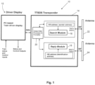
- Fig. 1 shows a transponder system 10 in accordance with a first embodiment.
- the transponder system 10 comprises a driver display module 12 connected to a transponder unit 14.
- the transponder unit 14 comprises a search module 16 and a reply module 18, both of which are under control of a processor system 20.
- the processor system 20 includes memory for storing machine code executable to implement the functions of the transponder system 10.
- the processor system 20 may include a clock generator, target range counters and some miscellaneous circuits.
- the transponder unit 14 has a unique identifier or address allocated to it which is used by the reply module 18 for validating a search signal received at the reply module 18 from a search module of another transponder system.
- the search module 16 may have a different unique address allocated to it which is used by the search module 16 to validate a reply signal received at the search module 16 from a reply module of another transponder system and for detection control.
- the allocated addresses are unique among a set of addresses allocated to transponder systems respectively associated with a set of trains operating on a railway system. It will be understood therefore that the addresses may not be universally unique, but merely need to be unique within the system in which they are allocated.
- Each of the search module 16 and the reply module 18 comprise wireless, i.e. radio, transceivers enabling each module 16, 18 to both send and receive signals.
- Each of the search module 16 and the reply module 18 has a respective directional antenna 22, 24.
- the antennas 22, 24 are preferably narrow beam directional antennas designed for line of sight communication, but in some applications omnidirectional antennas could be deployed.
- the transponder system 10 Whilst it is possible to configure the transponder system 10 as a single transponder system for a train, it is preferred to provide one transponder system 10 at a forward position on a train and one transponder system 10' at a rearward position on a train. Consequently, the forward transponder system 10 is utilized to determine a traffic situation forward of the train whilst the rearward transponder system 10' is utilized to determine a traffic situation rearward of the train. To avoid unintentional corruption of signals, the forward transponder system 10 and the rearward transponder system 10' use different, unique addresses. As such, the train has associated with it two unique addresses.
- the driver display module 12 is preferably a personal computer (PC) based system.
- the driver display module 12 is configured to receive data from the or both transponder systems 10 and to display to a driver an image of the traffic situation for the train.
- a separate driver display module could be provided for each of the forward and rearward transponder systems, it is preferred that data from both transponder systems on the train are fed to the driver display module 12, but the train may be provided with a driver display module in both the forward and rearward driving cabs of the train.
- Each such driver display module may be connected to both of the transponder systems.
- the transponder system 10 may be portable and powered by its own power supply. As such, the unique addresses assigned to the transponder system 10 are not necessarily train specific, i.e. are not necessarily linked to an identity of a train on which a transponder system is deployed.
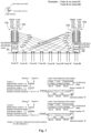
- Fig. 2 illustrates a first train "Train-A" 30 travelling on a same railway track as a second train “Train-B” 40 and shows the signals communicated between the forward transponder system 32 of Train-A 30 and the rearward transponder system 42 of Train-B 40.
- the forward transponder system 32 of Train-A 30 is allocated the unique identifier or address "#0002" and the rearward transponder system 42 of Train-B 40 is allocated the unique identifier or address "#0007".
- the search module of the forward transponder system 32 of Train-A 30 transmits a search signal (RF search pulse string) 50 in a forward direction of travel of Train-A 30.
- RF search pulse string search signal
- Search signal 50 is received at the reply module of rearward transponder system 42 of Train-B 40.
- the reply module processes the search signal 50 to determine if a transponder address #0007 carried in a reply transponder field of the search pulse string comprising search signal 50 matches the unique address #0007 allocated to the rearward transponder system 42 of Train-B 40. If the reply module of the rearward transponder system 42 of Train-B 40 determines no match then the validation fails and the reply module 'assumes' the search signal 50 is not intended for it.
- the reply module of the rearward transponder system 42 of Train-B 40 will not issue any reply signal in response to a false validation, although, in some embodiments, the reply module may be configured to issue a 'null' reply signal which at least identifies to the forward transponder system 32 of Train-A 30 of the presence of Train-B 40 within radio propagation distance of Train-A 30.
- the reply module of rearward transponder system 42 of Train-B 40 validates that the search signal 50 is intended for it
- the reply module transits a reply signal 52 which preferably at least carries the unique address #0007 of the rearward transponder system 42.
- the transponder system 32 processes said received reply signal in order to determine a separation distance between Train-A 30 and Train-B 40 based on a time taken from transmission of the search signal 50 to receipt of the reply signal 52 at said forward transponder system 32 of Train-A 30.
- the determination of the separation distance may take into account other factors such as the processing signal time and the position of the transponder unit relative to its end of the train if it is not actually positioned at the end of the train.
- the reply signal 52 is preferably transmitted on a different frequency to that used for the search signal 50.
- the transponder system 42 of Train-B 40 is referred to as the "rearward" transponder system 42 of Train-B 40. It will, however, be understood that said transponder system 42 of Train-B 40 might comprise its forward transponder system in the situation where Train-B 40 is, in fact, travelling towards Train-A 30. Consequently, in preferred embodiments, both the search signal 50 and the reply signal 52 may carry other data defining, for example, any one or more of the train status (emergency stopped due to mechanical problems, communication failure, normal stop at station platform, moving, direction of travel, speed), the identity of the track the train is on, position of the transponder (forward or rearward of its train), the type of train, etc. This information can be obtained locally by the respective transponder systems of the trains such that the transponder systems can operate in stand-alone modes without requiring data from external or centrally controlled systems.
- the "rearward" transponder system 42 of Train-B 40 is configured to include at least its own address #0007 in the reply signal 52, but preferably also the address #0002 of the forward transponder system 32 of Train-A 30. Consequently, once the reply signal 52 is received at the forward transponder system 32, the forward transponder system 32 processes the reply signal 52 to at least locally validate the address #0007 of the "rearward" transponder system 42 and preferably also to validate its own address #0002. Validation of the addresses is performed by comparing locally stored addresses with addresses retrieved from the respective search or reply signals 50, 52. Local validation of addresses has the benefit of ensuring that transponder systems process only those signals intended for them and thus avoid or at least reduce signal processing errors.
- a search module of the "rearward" transponder system 42 of Train-B 40 is configured to also transmit a search signal 60 and that a reply module of the forward transponder system 32 of Train-A 30 is configured to process said search signal 60 and, if local validation is positive, to transmit a reply signal 62.
- search and reply modules of a rearward transponder system 34 of Train-A 30 are configured operate in a rearward direction of Train-A 30 using the same methodology as herein described. This is also the case for search and reply modules of a forward transponder system 44 of Train-B 40. Consequently, all trains are provisioned with transponders systems which enable them to develop forward and rearward traffic situation displays.
- Data from the forward and rearward transponder systems 32, 34 of Train-A 30 can be provided to the driver display system 36 to thereby display to the driver the determined distance to Train-B 40 and to any other detected trains.
- the transponder systems may be configured to issue an alert or a warning to a driver when a predetermined minimum 'safety' distance with another train or at least another transponder system is breached which may warn of a potential collision.
- the transponder system may take into account other data such as train track data whereby a collision warning is not necessary if an on-coming train is known to be on a separate track.
- train track data whereby a collision warning is not necessary if an on-coming train is known to be on a separate track.
- the driver of Train-A 30 has display data showing the separation distance of Train-B 40, but that there appears to be no train detected within radio propagation distance behind Train-A 30.
- the display data shows the separation distance of Train-A 30 behind Train B 40, but that there appears to be no train detected within radio propagation distance in advance of Train-B 40.
- the system of the invention is not intended to replace existing safety systems, but to provide a back-up stand-alone system which a driver may use should other safety systems fail or at least fail to show the presence of other trains nearby.
- the transponder system is configured to periodically send search signals to detect other trains. This may be achieved by the transponder system sending search signals in a sequential basis working in turn through a list of known transponder addresses for other transponder systems associated with other trains and then waiting to receive reply signals.
- the use of the double addressing scheme described herein enables the generation of search signals in a polling methodology whereby other transponder systems are configured to only transmit a reply signal once they have validated their own address within a received search signal.
- the transponder systems are configured to include at least their own address in the reply signal.
- the use of double addressing is beneficial in that it reduces corruption of reply pulse strings caused by receiving multiple replies from close range targets at the same time.
- a maintenance team could be provisioned with one or more portable transponder systems as herein described whereby a stationary transponder system of the maintenance team could communicate with the transponders systems of trains to alert both the maintenance team and the train drivers of the presence of each other and, in particular, to warn the maintenance team of incoming train traffic.
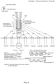
- Fig. 3 shows a similar scenario to Fig. 2 save for the presence of a third train, Train-C 60 on an adjacent track.
- the methodology described with respect to Fig. 2 applies to Fig. 3 where the display of Train-A 30 will show to its driver the separation distance to Train-B 40 and the separation distance to Train-C 60, but also that Train-B 40 is moving in the same direction as Train-A 30, whereas Train-C 60 is moving towards Train-A 30.
- the use of other data in the reply signal 62 from Train-C 60 to Train-A 30 may be used to determine that Train-C 60 is on a different track to that of Train-A 30 and thus there is no danger of collision.
- Fig. 4 shows the same scenario as Fig. 3 , but from the position of the driver of Train-B 40.
- the rearward transponder system 42 of Train-B 40 informs the driver of the separation distance with Train-A 30 and that it is moving in the same direction and possibly on the same track as Train-B 40, but that Train-C 60 is moving away from Train-B 40 on a different track.
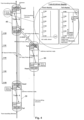
- Fig. 5 is a more detailed view of the transponder system 10 of Fig. 1 .
- the transponder system 10 may be connected to external systems to receive data.
- the transponder system 10 may include a global positioning system (GPS) antenna 80 and sensor 82 to receive GPS position data.
- GPS data is included as as auxiliary input to enhance range accuracy up to few meters.
- the search module 16 comprises a search pulse string generator 100 with a RF modulator 102 to modulate a search pulse string comprising a search signal at a first frequency F1.
- the search module 16 also includes a reply pulse string processor 104 and associated RF receiver 106 for demodulating a received reply signal on a second, different frequency F2.
- An antenna switch 108 enables switching between the frequencies F1 and F2 for the high gain, directional antenna 22.
- a reply pulse string generator 110 with a RF modulator 112 to modulate a reply signal on the second frequency F2.
- a search pulse string processor 114 is provided to process received search signals from other transponder systems and has an associated demodulator 116 for demodulating a received search signal on the first frequency F1.
- An antenna switch 118 enables switching between the frequencies F1 and F2 for the high gain, directional antenna 24.
- the driver display system 12 may include a data connection 120 to other transponder systems and a train control interface unit 122.
- a track detection system 130 for detecting the existence of one or more adjacent tracks to that on which the train is travelling.
- the track detection unit 130 may comprise a laser track detection unit comprising sets of left and right laser sensors 132, 134 carried on the train.
- the sets of sensors 132, 134 are connected to a track detection unit 136 which communicates with the main processor 20 of the transponder system 10.
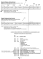
- Fig. 6 illustrates preferred search signal pulse strings 140 and preferred reply signal pulse strings 160.
- the search signal pulse string 140 includes at least a sender transponder address field 142 and a reply transponder address field 144, i.e. the address of the transponder to which a search signal is addressed.
- the search signal pulse string 140 may include a preamble field 146, a header 148, control and status bits 150, sensor bits 152, CRC byte 154 and an end frame 156.
- the reply signal pulse string has a same format.
- the control and status bits 150 may include track information output from the track detection unit.
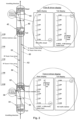
- Figs. 7 and 8 illustrate two scenarios where one or more trains are using a track detector unit to identify the existence of adjacent train tracks.
- the sets of sensors 132, 134 carried on the trains are arranged to sense reflections of laser light emitted at different predetermined angles from the sides of the train.
- the number of sensors in each set 132, 134 may be selected as the maximum number of anticipated tracks at any point in the railway system, although the number of sensors provided may be more limited than that and configured to detect the nearest few adjacent tracks.
- Train-A 30 is on a rightmost track such that its right set of sensors 132 receive no reflections indicating the absence of any tracks to the right of Train-A 30.
- Train-A 30 receives from seven tracks enabling the transponder system 10 of Train-A 30 to determine that there are in total eight tracks comprising the seven detected tracks and the track on which Train-A 30 is running.
- Train-B 40 also determines that there are eight tracks by sensing on its right side seven tracks, no tracks on its left side, and taking into account the track it is running on.
- Train-A 30 is running on track 3 and thus detects reflections from two tracks to its right and five tracks to its left.
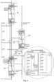
- Fig. 9 illustrates a similar situation as in Fig. 2 , but where Train-A 30 and Train-B 40 are both configured with track detection systems.
- the transponder systems 10 of the trains were receiving track information from an external source or some other source such as a stored map of the railway network, but this information may not be available or be lost if other train safety systems suffer a failure. Consequently, the transponder system 10 used in the scenario of Fig. 9 has been enhanced with a track detection system so that the transponder system can locally determine the number of tracks to its right and its left and thus to locally determine which track its train is running on.
- the track identity information can be included in the search and reply signals between transponder systems in additional to other train status information such as direction of travel, etc.
- the transponder systems 10 of Train-A 30 and Train-B 40 are able to inform each other that the two trains are running on the same track, are running towards each other, i.e. head-on, and can determine their separation distance.
- the transponder systems 10 are able to alert their respective driver to a potential head-on collision so that the drivers may take preventive action such as stopping their trains.
- the enhanced transponder systems 10 for Train-A 30 and Train-B 40 are able to determine that their respective trains are running on different tracks and thus there is no risk of a collision.
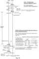
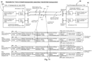
- Fig. 11 illustrates a modified search signal and reply signal scheme whereby the transponder system 32 for Train-A 30 is configured to issue two successive search pulse strings.
- a first search pulse string PS-1 is transmitted to a targeted reply module of another transponder system, namely the reply module of the transponder system 42 of Train-B 40 in this example.
- the transponder system 42 of Train-B 40 is configured to respond in the manner as hereinbefore described such that it transmits a first reply pulse string PS-2 to the transponder system 32 of Train-A30.
- the transponder system 32 of Train-A 30 determines a first separation distance d1 between the two trains 30, 40.
- the transponder system 32 of Train-A 30 is configured to send a second search pulse string PS-3 to the reply module of the transponder system 42 of Train-B 40, where the string PS-3 preferably includes the measured target range, i.e. separation distance d1, from the first search/reply cycle.
- the predetermined short period is the search repetition period whereby the transponder system 32 selects a next target address from a stored list of addresses and repeats the search/reply cycle as mentioned above.
- the measured target range may be included in a reserved field of the string PS-3.
- the reply module 42 of the transponder system of Train-B 40 transmits a second reply pulse string PS-4 from which the transponder system 32 of Train-A determines a second measured target range, i.e. a second separation distance d2.
- the transponder system 32 of Train-A may be configured to use the second separation distance d2 in place of the first separation distance d1 or to calculate an average of d1 and d2 and use the resulting average separation distance.
- the second search pulse string PS-3 may still succeed in obtaining a reply such that a separation distance between the two trains 30, 40 can be obtained.
- the same procedure, but in reverse, could be implemented by the search module of the transponder system 42 of Train-B 40 and the reply module of the transponder system 32 of Train-A 30.
- the foregoing systems and methods may be applied to other vehicles such as, but not limited to, automobiles and trams.
- the system and method of the invention are particularly applicable to vehicle systems running on a pathway comprising any of: a defined pathway; a road lane; a railway track; or a tramway track.
- the method of the invention may be modified whereby the search signal transmitted by a first transponder system includes time data and whereby the method includes the step, after the validation step at a second transponder system receiving the search signal, of determining from its own local time data and the time data included in the received search signal a separation distance between the two transponders systems.
- This calculated separation distance can be included as distance data in the reply signal such that the distance data included in the reply signal is used at the first transponder system as a distance as a distance check mechanism when it itself is determining the separation distance.
- the method may further be modified by arranging a first transponder system to determine a direction of travel an object or vehicle associated with a second transponder system from a rate of change of distances determined from successive reply signals.
- the invention provides a method and system for determining a separation distance between a first object and a second object. It is envisaged that at least one of the objects is a movable vehicle such as a train.
- the method comprises using a search module associated with a first object where said search module comprises a first transponder having a unique address.
- the method includes using a reply module associated with a second object where said reply module comprises a second transponder having a different, unique address.
- the method includes the search module transmitting a search signal on a first frequency, said search signal including the address of the first transponder and the address of the second transponder.
- the reply module receives the search signal and locally validates the address included in said received search signal for the second transponder, whereby, if the validation is positive; the reply module transmits a reply signal on a second, different frequency, said reply signal including the address of the second transponder and the address of the first transponder.
- the search module receives the reply signal and locally validates the address included in said received reply signal for the second transponder whereby, if the validation is positive, the search module determines a separation distance between the first object and the second object based on a time taken from transmission of the search signal to receipt of the reply signal at said search module.
Landscapes
- Physics & Mathematics (AREA)
- General Physics & Mathematics (AREA)
- Engineering & Computer Science (AREA)
- Mechanical Engineering (AREA)
- Radar, Positioning & Navigation (AREA)
- Remote Sensing (AREA)
- Atmospheric Sciences (AREA)
- Life Sciences & Earth Sciences (AREA)
- Computer Networks & Wireless Communication (AREA)
- Business, Economics & Management (AREA)
- Emergency Management (AREA)
- Train Traffic Observation, Control, And Security (AREA)
- Radar Systems Or Details Thereof (AREA)
Claims (15)
- Verfahren zum Bestimmen eines Trennungsabstands zwischen einem ersten Objekt (30) und einem zweiten Objekt (40), wobei jeweils das erste und das zweite Objekt (30, 40) einen jeweiligen Transponder (32, 42) mit einer jeweiligen eindeutigen Adresse aufweist, wobei das Verfahren die folgenden Schritte umfasst::Senden eines Suchsignals auf einer ersten Frequenz vom Transponder (32) des ersten Objekts (30), wobei das Suchsignal die Adresse des Transponders (32) des ersten Objekts und die Adresse des Transponders (42) des zweiten Objekts (40) enthält, wobei das Suchsignal für das Empfangen und das Verarbeiten am Transponder (42) des zweiten Objekts (40) bestimmt ist, um eine oder beide der im Suchsignal enthaltenen Adressen lokal zu validieren;Empfangen eines vom Transponder (40) des zweiten Objekts (40) gesendeten Antwortsignals auf einer zweiten, unterschiedlichen Frequenz am Transponder (32) des ersten Objekts (30), wenn die Validierung positiv ist; undVerarbeiten des empfangenen Antwortsignals am Transponder (32) des ersten Objekts (30), um den Trennungsabstand zwischen dem ersten Objekt (30) und dem zweiten Objekt (40) auf der Grundlage einer Zeit, die vom Senden des Suchsignals bis zum Empfangen des Antwortsignals am Transponder (32) des ersten Objekts (30) vergeht, zu bestimmen;wobei der Transponder (32) des ersten Objekts (30) ein erstes und ein zweites aufeinanderfolgendes Suchsignal sendet, wobei jeweils das erste und das zweite aufeinanderfolgende Suchsignal in einer jeweiligen vorbestimmten Suchwiederholungsperiode gesendet und der Prozess für eine nächste Zieladresse aus einer gespeicherten Liste von Adressen wiederholt wird; und wobei das zweite aufeinanderfolgende Suchsignal den bestimmten Trennungsabstand zwischen dem ersten Objekt (30) und dem zweiten Objekt (40) enthält.
- Verfahren nach Anspruch 1, wobei der Schritt des Empfangens des Antwortsignals auf einer zweiten, unterschiedlichen Frequenz von dem Transponder (42) des zweiten Objekts (40) das Empfangen mindestens der Adresse des Transponders (42) des zweiten Objekts (40) in dem Antwortsignal umfasst; und, sobald das Antwortsignal am Transponder (32) des ersten Objekts (30) empfangen wird, das Verfahren ferner die folgenden Schritte umfasst:Verarbeiten des empfangenen Antwortsignals am Transponder (32) des ersten Objekts (30), um die in dem empfangenen Antwortsignal enthaltene Adresse für den Transponder (42) des zweiten Objekts (40) lokal zu validieren, und, wenn die Validierung positiv ist;Bestimmen des Trennungsabstands zwischen dem ersten Objekt (30) und dem zweiten Objekt (40).
- Verfahren nach Anspruch 2, wobei der Schritt des Empfangens des Antwortsignals auf einer zweiten, unterschiedlichen Frequenz von dem Transponder (42) des zweiten Objekts (40) das Empfangen der Adresse des Transponders (32) des ersten Objekts (30) in dem Antwortsignal umfasst.
- Verfahren nach Anspruch 1, wobei sich mindestens eines von dem ersten Objekt (30) und dem zweiten Objekt (40) bewegt und/oder mindestens eines von dem ersten Objekt (30) und dem zweiten Objekt (40) ein Fahrzeug umfasst.
- Verfahren nach Anspruch 1, wobei mindestens eines von dem ersten Objekt (30) und dem zweiten Objekt (40) ein Fahrzeug umfasst, das sich entlang eines Weges bewegt, der Folgendes umfasst: einen definierten Weg; einen Flugweg; eine Straßenspur; ein Eisenbahngleis oder ein Straßenbahngleis.
- Verfahren nach Anspruch 1, wobei, wenn das lokale Validieren am Transponder (42) des zweiten Objekts (40) negativ ist, dann entweder am Transponder (32) des ersten Objekts (30) ein Antwortsignal empfangen wird, das ein "Null"-Antwortsignal umfasst, oder kein Antwortsignal von dem Transponder (42) des zweiten Objekts (40) empfangen wird.
- Verfahren nach Anspruch 3, wobei der Schritt des lokalen Validierens des Antwortsignals am Transponder (32) des ersten Objekts (30) das lokale Validieren der Adresse für den Transponder (32) des ersten Objekts (30), die in dem Antwortsignal empfangen wurde, umfasst.
- Verfahren nach Anspruch 1, wobei das Suchsignal Zeitdaten enthält und das Verfahren nach dem Validierungsschritt am Transponder (42) des zweiten Objekts (40) den Schritt des Bestimmens eines Abstands des zweiten Objekts (40) vom ersten Objekt (30) aus lokalen Zeitdaten und den im Suchsignal enthaltenen Zeitdaten enthält.
- Verfahren nach Anspruch 8, wobei das Antwortsignal Abstandsdaten enthält, die einen am Transponder (42) des zweiten Objekts (40) berechneten Abstand umfassen.
- Verfahren nach Anspruch 9, wobei die Abstandsdaten, die im Antwortsignal empfangen wurden, am Transponder (32) des ersten Objekts (30) nach dem Schritt des Bestimmens eines Trennungsabstands als Abstandskontrollmechanismus verwendet werden.
- Verfahren nach Anspruch 5, wobei das Antwortsignal Wegdaten enthält, die einen Weg für das Fahrzeug des Transponders (42) des zweiten Objekts (40) identifizieren, und der Transponder (32) des ersten Objekts (30) die Wegdaten verwendet, um zu bestimmen, ob sich das erste Fahrzeug auf demselben Weg wie das Objekt oder Fahrzeug des Transponders (42) des zweiten Objekts (40) befindet.
- Verfahren nach Anspruch 1, wobei der Transponder (32) des ersten Objekts (30) periodisch Suchsignale an eine Vielzahl anderer Transponder sendet, wobei jeder Transponder eine eindeutige Adresse aufweist und mit einem jeweiligen Objekt oder Fahrzeug verbunden ist.
- Verfahren nach Anspruch 12, wobei der Transponder (32) des ersten Objekts (30) die Fahrtrichtung eines Objekts oder Fahrzeugs, das mit einem anderen Transponder verbunden ist, aus Folgendem bestimmt: Fahrtrichtungsdaten, die in dem Antwortsignal enthalten sind; und aus einer Änderungsrate von Abständen, die aus aufeinanderfolgenden Antwortsignalen bestimmt wird.
- Verfahren nach Anspruch 1, wobei jeweils der Transponder (32) des ersten Objekts (30) und der Transponder (42) des zweiten Objekts (40) ein Suchmodul und ein Antwortmodul umfasst, so dass jeweils der Transponder (32) des ersten Objekts (30) und der Transponder (42) des zweiten Objekts (40) sowohl im Such- als auch im Antwortmodus für ihre jeweiligen Objekte arbeiten können.
- System zum Bestimmen eines Trennungsabstands zwischen einem ersten Objekt (30) und einem zweiten Objekt (40), wobei das System Folgendes umfasst:ein Suchmodul (16), das mit dem ersten Objekt (30) verbunden ist, wobei das Suchmodul (16) einen Transponder (32) des ersten Objekts (30) mit einer eindeutigen Adresse umfasst, wobei das Suchmodul (16) so konfiguriert ist, dass es ein Suchsignal auf einer ersten Frequenz an einen Transponder (42) sendet, der mit einem zweiten Objekt (40) verbunden ist, wobei der Transponder (42) des zweiten Objekts (40) eine andere eindeutige Adresse aufweist, wobei das Suchsignal die Adresse des Transponders (32) des ersten Objekts (30) und die Adresse des Transponders (42) des zweiten Objekts (40) enthält, wobei das Suchsignal für das Empfangen und das Verarbeiten am Transponder (42) des zweiten Objekts (40) bestimmt ist, um eine oder beide der in dem Suchsignal enthaltenen Adressen lokal zu validieren;wobei das Suchmodul (16) so konfiguriert ist, dass es auf der zweiten, unterschiedlichen Frequenz ein Antwortsignal empfängt, das vom Transponder (42) des zweiten Objekts (40) gesendet wird, wenn die Validierung positiv ist, und dass es den Trennungsabstand zwischen dem ersten Objekt (30) und dem zweiten Objekt (40) auf der Grundlage einer Zeit, die vom Senden des Suchsignals bis zum Empfangen des Antwortsignals am Suchmodul (16) vergeht, zu bestimmen;wobei der Transponder (32) des ersten Objekts (30) so konfiguriert ist, dass er ein erstes und ein zweites aufeinanderfolgendes Suchsignal sendet, wobei jeweils das erste und das zweite aufeinanderfolgende Suchsignal in einer jeweiligen vorbestimmten Suchwiederholungsperiode gesendet und der Prozess für eine nächste Zieladresse aus einer gespeicherten Liste von Adressen wiederholt wird; und wobei das zweite aufeinanderfolgende Suchsignal den bestimmten Trennungsabstand zwischen dem ersten Objekt (30) und dem zweiten Objekt (40) enthält.
Applications Claiming Priority (2)
| Application Number | Priority Date | Filing Date | Title |
|---|---|---|---|
| US201762484079P | 2017-04-11 | 2017-04-11 | |
| PCT/CN2018/082700 WO2018188615A1 (en) | 2017-04-11 | 2018-04-11 | A train traffic situation display system |
Publications (4)
| Publication Number | Publication Date |
|---|---|
| EP3609765A1 EP3609765A1 (de) | 2020-02-19 |
| EP3609765A4 EP3609765A4 (de) | 2021-01-13 |
| EP3609765C0 EP3609765C0 (de) | 2024-09-04 |
| EP3609765B1 true EP3609765B1 (de) | 2024-09-04 |
Family
ID=63710205
Family Applications (1)
| Application Number | Title | Priority Date | Filing Date |
|---|---|---|---|
| EP18785093.8A Active EP3609765B1 (de) | 2017-04-11 | 2018-04-11 | System zur anzeige einer zugverkehrssituation |
Country Status (5)
| Country | Link |
|---|---|
| US (1) | US10370015B2 (de) |
| EP (1) | EP3609765B1 (de) |
| CN (1) | CN108688691B (de) |
| SG (1) | SG11201804777TA (de) |
| WO (1) | WO2018188615A1 (de) |
Families Citing this family (12)
| Publication number | Priority date | Publication date | Assignee | Title |
|---|---|---|---|---|
| AT520261B1 (de) * | 2017-08-08 | 2020-10-15 | Siemens Mobility Austria Gmbh | Kollisionsschutz für Schienenfahrzeuge |
| SG11202105139UA (en) | 2018-12-14 | 2021-06-29 | Thales Canada Inc | Rail vehicle obstacle avoidance and vehicle localization |
| US12371078B2 (en) * | 2019-12-23 | 2025-07-29 | Westinghouse Air Brake Technologies Corporation | Vehicle monitoring system |
| TWI735201B (zh) * | 2020-04-09 | 2021-08-01 | 台灣高速鐵路股份有限公司 | 軌道車廂的車端牆顯示裝置 |
| US12397833B2 (en) * | 2020-08-24 | 2025-08-26 | Siemens Mobility, Inc. | Prevention of collision between trains |
| CN112434038B (zh) * | 2020-11-27 | 2024-01-19 | 重庆市轨道交通(集团)有限公司 | 一种列车跨线进路搜索方法、系统、电子设备及存储介质 |
| CN112462359B (zh) * | 2020-11-30 | 2024-07-26 | 北京博途智控科技有限公司 | 一种基于二次雷达的线路识别方法和系统 |
| CN116198561B (zh) * | 2021-11-30 | 2025-10-17 | 比亚迪股份有限公司 | 应答器合法性的防护方法、装置、车载控制器及列车 |
| CN115056819B (zh) * | 2022-06-23 | 2023-08-25 | 交控科技股份有限公司 | 基于应答器的列车轮径校正方法及装置 |
| CN115339485A (zh) * | 2022-08-11 | 2022-11-15 | 天津津航计算技术研究所 | 一种适用于地铁列车的辅助防碰撞系统及方法 |
| CN115402375B (zh) * | 2022-08-30 | 2024-06-14 | 通号城市轨道交通技术有限公司 | 行车电子地图获取方法及系统 |
| US20250316169A1 (en) * | 2024-04-08 | 2025-10-09 | Qualcomm Incorporated | Handling emergency vehicle alerts in cellular-vehicle-to-everything |
Citations (1)
| Publication number | Priority date | Publication date | Assignee | Title |
|---|---|---|---|---|
| EP2419313B1 (de) * | 2009-04-13 | 2014-04-02 | Siemens Aktiengesellschaft | Kollisionsvermeidungsverfahren, -system und -vorrichtung |
Family Cites Families (25)
| Publication number | Priority date | Publication date | Assignee | Title |
|---|---|---|---|---|
| US2762913A (en) * | 1955-06-13 | 1956-09-11 | William L Jepson | Railway train proximity warning system |
| US4403208A (en) * | 1975-10-23 | 1983-09-06 | Hodgson R W | Warning-signal-producing system for a motor vehicle responsive to a vehicle-presence-indicating radio wave signal emitted by another vehicle and indicative of its presence |
| US4965583A (en) * | 1989-05-02 | 1990-10-23 | Charles Broxmeyer | Collision avoidance system for automatically controlled vehicles moving at short headways |
| CN1124858A (zh) | 1994-12-12 | 1996-06-19 | 黄金富 | 运动装置在运行中的定位、自动导航与防撞系统 |
| EP0825580B1 (de) * | 1996-07-25 | 2002-03-20 | Matsushita Electric Industrial Co., Ltd. | Übertragungssystem und Übertragungsverfahren für ein Übertragungssystem |
| EP0825581B1 (de) * | 1996-07-25 | 2002-07-03 | Matsushita Electric Industrial Co., Ltd. | Mobileinheit und Mobileinheit-Unterstützungssystem |
| JP2000322696A (ja) * | 1999-05-07 | 2000-11-24 | Honda Motor Co Ltd | 隊列走行制御装置 |
| CN1325805A (zh) | 2000-05-31 | 2001-12-12 | 赵连银 | 多频无线电火车防撞系统 |
| US20020070849A1 (en) * | 2000-12-07 | 2002-06-13 | Teicher Martin H. | Signaling system for vehicles travelling in a convoy |
| US6759948B2 (en) * | 2001-09-21 | 2004-07-06 | Time Domain Corporation | Railroad collision avoidance system and method for preventing train accidents |
| US20070233337A1 (en) * | 2005-09-14 | 2007-10-04 | Plishner Paul J | Semi-autonomous guidance system for a vehicle |
| JP2011010515A (ja) | 2009-06-29 | 2011-01-13 | Toshiba Corp | 電気車の無線保安用制御装置 |
| US20120038489A1 (en) * | 2010-08-12 | 2012-02-16 | Goldshmidt Ehud | System and method for spontaneous p2p communication between identified vehicles |
| WO2012158906A1 (en) | 2011-05-19 | 2012-11-22 | Metrom Rail, Llc | Collision avoidance system for rail line vehicles |
| CN103546357B (zh) * | 2012-07-17 | 2017-03-15 | 中车大同电力机车有限公司 | 不同重联网络机车之间的通信方法及系统、网关 |
| CN102756747B (zh) | 2012-07-31 | 2015-06-10 | 中国科学院上海高等研究院 | 基于声波和电磁波的列车防撞系统及其防撞方法 |
| CN103071596B (zh) | 2013-01-22 | 2014-07-30 | 昆明理工大学 | 一种回收氧化型脉锡矿泥尾矿中细粒和微细粒锡石的方法 |
| CN103171596B (zh) * | 2013-03-11 | 2015-10-28 | 同济大学 | 一种轨道交通列车的防撞预警方法 |
| CN103818406A (zh) * | 2013-11-12 | 2014-05-28 | 嘉兴中科声学科技有限公司 | 一种地铁辅助防撞系统及防撞方法 |
| US9994242B2 (en) * | 2014-10-03 | 2018-06-12 | Harsco Technologies LLC | V-aware end of train device |
| CN106254406B (zh) * | 2015-06-11 | 2020-12-18 | 腾讯科技(深圳)有限公司 | 一种位置信息分享方法和设备 |
| US20160363663A1 (en) * | 2015-06-15 | 2016-12-15 | Humatics Corporation | High precision time of flight measurement system for industrial automation |
| CN105730475A (zh) * | 2016-02-01 | 2016-07-06 | 成都可益轨道技术有限公司 | 一种基于点对点精确测距的铁路列车防碰撞防追尾装置 |
| CN105827692A (zh) * | 2016-03-10 | 2016-08-03 | 阿里巴巴集团控股有限公司 | 一种消息推送方法和装置 |
| CN208325259U (zh) * | 2018-04-11 | 2019-01-04 | 朱树棠 | 用于确定第一对象和第二对象之间的间距的系统 |
-
2018
- 2018-04-11 CN CN201810320863.5A patent/CN108688691B/zh active Active
- 2018-04-11 US US15/950,673 patent/US10370015B2/en active Active
- 2018-04-11 SG SG11201804777TA patent/SG11201804777TA/en unknown
- 2018-04-11 EP EP18785093.8A patent/EP3609765B1/de active Active
- 2018-04-11 WO PCT/CN2018/082700 patent/WO2018188615A1/en not_active Ceased
Patent Citations (1)
| Publication number | Priority date | Publication date | Assignee | Title |
|---|---|---|---|---|
| EP2419313B1 (de) * | 2009-04-13 | 2014-04-02 | Siemens Aktiengesellschaft | Kollisionsvermeidungsverfahren, -system und -vorrichtung |
Also Published As
| Publication number | Publication date |
|---|---|
| EP3609765C0 (de) | 2024-09-04 |
| WO2018188615A1 (en) | 2018-10-18 |
| CN108688691A (zh) | 2018-10-23 |
| US20180290673A1 (en) | 2018-10-11 |
| SG11201804777TA (en) | 2018-11-29 |
| EP3609765A1 (de) | 2020-02-19 |
| EP3609765A4 (de) | 2021-01-13 |
| CN108688691B (zh) | 2021-01-05 |
| US10370015B2 (en) | 2019-08-06 |
Similar Documents
| Publication | Publication Date | Title |
|---|---|---|
| EP3609765B1 (de) | System zur anzeige einer zugverkehrssituation | |
| US12397832B2 (en) | Rail vehicle signal enforcement and separation control | |
| US10816986B2 (en) | Systems for vehicle collision avoidance | |
| US12038765B2 (en) | Vehicle control system and method | |
| US9682654B2 (en) | Apparatus and method for warning loss of control of a vehicle using vehicle-to-vehicle communications | |
| US6765495B1 (en) | Inter vehicle communication system | |
| US20130200223A1 (en) | Crossing safety system | |
| US9019115B2 (en) | Warning horn control system, radar system, and method | |
| CN106526595B (zh) | 一种用于轨交车辆防撞预警雷达系统 | |
| WO2004047047A1 (en) | Method and system for avoiding traffic collisions | |
| CN101165509A (zh) | 辅助倒车运动的防撞系统及方法 | |
| US11753010B2 (en) | Systems and methods for determining passage status of a train at a railroad crossing | |
| CN110775110A (zh) | 基于车车通信的列车控制系统 | |
| CN105894858A (zh) | 一种车辆紧急刹车预警系统 | |
| CN112776855A (zh) | 轨道车辆及列车控制管理系统、用于防撞的控制方法 | |
| CN105730475A (zh) | 一种基于点对点精确测距的铁路列车防碰撞防追尾装置 | |
| CN116279667A (zh) | 一种列车及其安全防护系统和方法 | |
| CN208325259U (zh) | 用于确定第一对象和第二对象之间的间距的系统 | |
| US11614741B2 (en) | Vehicle control system and method | |
| JP2005537586A (ja) | 無線により危険警告を行う装置 | |
| AU2024227255A1 (en) | Vehicle control system and method | |
| CN205344923U (zh) | 一种基于点对点精确测距的铁路列车防碰撞防追尾装置 | |
| JPH07257377A (ja) | 列車用衝突防止支援システム並びにこれを構成する前方及び後方列車用装置 | |
| AU2025201122B2 (en) | A Driver Warning System for Railway Level Crossings | |
| CN102955156A (zh) | 盲点检测系统 |
Legal Events
| Date | Code | Title | Description |
|---|---|---|---|
| STAA | Information on the status of an ep patent application or granted ep patent |
Free format text: STATUS: THE INTERNATIONAL PUBLICATION HAS BEEN MADE |
|
| PUAI | Public reference made under article 153(3) epc to a published international application that has entered the european phase |
Free format text: ORIGINAL CODE: 0009012 |
|
| STAA | Information on the status of an ep patent application or granted ep patent |
Free format text: STATUS: REQUEST FOR EXAMINATION WAS MADE |
|
| 17P | Request for examination filed |
Effective date: 20191108 |
|
| AK | Designated contracting states |
Kind code of ref document: A1 Designated state(s): AL AT BE BG CH CY CZ DE DK EE ES FI FR GB GR HR HU IE IS IT LI LT LU LV MC MK MT NL NO PL PT RO RS SE SI SK SM TR |
|
| AX | Request for extension of the european patent |
Extension state: BA ME |
|
| DAV | Request for validation of the european patent (deleted) | ||
| DAX | Request for extension of the european patent (deleted) | ||
| A4 | Supplementary search report drawn up and despatched |
Effective date: 20201215 |
|
| RIC1 | Information provided on ipc code assigned before grant |
Ipc: B61L 25/08 20060101ALI20201209BHEP Ipc: G01S 13/93 20200101ALI20201209BHEP Ipc: G01S 13/08 20060101ALI20201209BHEP Ipc: B61L 23/22 20060101ALI20201209BHEP Ipc: G08G 1/16 20060101ALI20201209BHEP Ipc: B61L 25/02 20060101ALI20201209BHEP Ipc: B61L 23/34 20060101AFI20201209BHEP Ipc: B61L 15/00 20060101ALI20201209BHEP |
|
| REG | Reference to a national code |
Ref country code: DE Ref legal event code: R079 Free format text: PREVIOUS MAIN CLASS: B61L0023340000 Ipc: G08G0001160000 Ref document number: 602018074000 Country of ref document: DE |
|
| GRAP | Despatch of communication of intention to grant a patent |
Free format text: ORIGINAL CODE: EPIDOSNIGR1 |
|
| STAA | Information on the status of an ep patent application or granted ep patent |
Free format text: STATUS: GRANT OF PATENT IS INTENDED |
|
| RIC1 | Information provided on ipc code assigned before grant |
Ipc: B61L 23/22 20060101ALI20240223BHEP Ipc: B61L 15/00 20060101ALI20240223BHEP Ipc: B61L 25/08 20060101ALI20240223BHEP Ipc: B61L 23/34 20060101ALI20240223BHEP Ipc: B61L 25/02 20060101ALI20240223BHEP Ipc: G01S 13/76 20060101ALI20240223BHEP Ipc: G08G 1/16 20060101AFI20240223BHEP |
|
| INTG | Intention to grant announced |
Effective date: 20240402 |
|
| GRAS | Grant fee paid |
Free format text: ORIGINAL CODE: EPIDOSNIGR3 |
|
| GRAA | (expected) grant |
Free format text: ORIGINAL CODE: 0009210 |
|
| STAA | Information on the status of an ep patent application or granted ep patent |
Free format text: STATUS: THE PATENT HAS BEEN GRANTED |
|
| AK | Designated contracting states |
Kind code of ref document: B1 Designated state(s): AL AT BE BG CH CY CZ DE DK EE ES FI FR GB GR HR HU IE IS IT LI LT LU LV MC MK MT NL NO PL PT RO RS SE SI SK SM TR |
|
| REG | Reference to a national code |
Ref country code: GB Ref legal event code: FG4D |
|
| REG | Reference to a national code |
Ref country code: CH Ref legal event code: EP |
|
| REG | Reference to a national code |
Ref country code: IE Ref legal event code: FG4D |
|
| REG | Reference to a national code |
Ref country code: DE Ref legal event code: R096 Ref document number: 602018074000 Country of ref document: DE |
|
| U01 | Request for unitary effect filed |
Effective date: 20240924 |
|
| U07 | Unitary effect registered |
Designated state(s): AT BE BG DE DK EE FI FR IT LT LU LV MT NL PT RO SE SI Effective date: 20241017 |
|
| PG25 | Lapsed in a contracting state [announced via postgrant information from national office to epo] |
Ref country code: NO Free format text: LAPSE BECAUSE OF FAILURE TO SUBMIT A TRANSLATION OF THE DESCRIPTION OR TO PAY THE FEE WITHIN THE PRESCRIBED TIME-LIMIT Effective date: 20241204 |
|
| PG25 | Lapsed in a contracting state [announced via postgrant information from national office to epo] |
Ref country code: GR Free format text: LAPSE BECAUSE OF FAILURE TO SUBMIT A TRANSLATION OF THE DESCRIPTION OR TO PAY THE FEE WITHIN THE PRESCRIBED TIME-LIMIT Effective date: 20241205 Ref country code: PL Free format text: LAPSE BECAUSE OF FAILURE TO SUBMIT A TRANSLATION OF THE DESCRIPTION OR TO PAY THE FEE WITHIN THE PRESCRIBED TIME-LIMIT Effective date: 20240904 |
|
| PG25 | Lapsed in a contracting state [announced via postgrant information from national office to epo] |
Ref country code: HR Free format text: LAPSE BECAUSE OF FAILURE TO SUBMIT A TRANSLATION OF THE DESCRIPTION OR TO PAY THE FEE WITHIN THE PRESCRIBED TIME-LIMIT Effective date: 20240904 |
|
| PG25 | Lapsed in a contracting state [announced via postgrant information from national office to epo] |
Ref country code: ES Free format text: LAPSE BECAUSE OF FAILURE TO SUBMIT A TRANSLATION OF THE DESCRIPTION OR TO PAY THE FEE WITHIN THE PRESCRIBED TIME-LIMIT Effective date: 20240904 Ref country code: RS Free format text: LAPSE BECAUSE OF FAILURE TO SUBMIT A TRANSLATION OF THE DESCRIPTION OR TO PAY THE FEE WITHIN THE PRESCRIBED TIME-LIMIT Effective date: 20241204 |
|
| PG25 | Lapsed in a contracting state [announced via postgrant information from national office to epo] |
Ref country code: RS Free format text: LAPSE BECAUSE OF FAILURE TO SUBMIT A TRANSLATION OF THE DESCRIPTION OR TO PAY THE FEE WITHIN THE PRESCRIBED TIME-LIMIT Effective date: 20241204 Ref country code: PL Free format text: LAPSE BECAUSE OF FAILURE TO SUBMIT A TRANSLATION OF THE DESCRIPTION OR TO PAY THE FEE WITHIN THE PRESCRIBED TIME-LIMIT Effective date: 20240904 Ref country code: NO Free format text: LAPSE BECAUSE OF FAILURE TO SUBMIT A TRANSLATION OF THE DESCRIPTION OR TO PAY THE FEE WITHIN THE PRESCRIBED TIME-LIMIT Effective date: 20241204 Ref country code: HR Free format text: LAPSE BECAUSE OF FAILURE TO SUBMIT A TRANSLATION OF THE DESCRIPTION OR TO PAY THE FEE WITHIN THE PRESCRIBED TIME-LIMIT Effective date: 20240904 Ref country code: GR Free format text: LAPSE BECAUSE OF FAILURE TO SUBMIT A TRANSLATION OF THE DESCRIPTION OR TO PAY THE FEE WITHIN THE PRESCRIBED TIME-LIMIT Effective date: 20241205 Ref country code: ES Free format text: LAPSE BECAUSE OF FAILURE TO SUBMIT A TRANSLATION OF THE DESCRIPTION OR TO PAY THE FEE WITHIN THE PRESCRIBED TIME-LIMIT Effective date: 20240904 |
|
| PG25 | Lapsed in a contracting state [announced via postgrant information from national office to epo] |
Ref country code: IS Free format text: LAPSE BECAUSE OF FAILURE TO SUBMIT A TRANSLATION OF THE DESCRIPTION OR TO PAY THE FEE WITHIN THE PRESCRIBED TIME-LIMIT Effective date: 20250104 |
|
| PG25 | Lapsed in a contracting state [announced via postgrant information from national office to epo] |
Ref country code: SM Free format text: LAPSE BECAUSE OF FAILURE TO SUBMIT A TRANSLATION OF THE DESCRIPTION OR TO PAY THE FEE WITHIN THE PRESCRIBED TIME-LIMIT Effective date: 20240904 |
|
| PG25 | Lapsed in a contracting state [announced via postgrant information from national office to epo] |
Ref country code: CZ Free format text: LAPSE BECAUSE OF FAILURE TO SUBMIT A TRANSLATION OF THE DESCRIPTION OR TO PAY THE FEE WITHIN THE PRESCRIBED TIME-LIMIT Effective date: 20240904 |
|
| PG25 | Lapsed in a contracting state [announced via postgrant information from national office to epo] |
Ref country code: SK Free format text: LAPSE BECAUSE OF FAILURE TO SUBMIT A TRANSLATION OF THE DESCRIPTION OR TO PAY THE FEE WITHIN THE PRESCRIBED TIME-LIMIT Effective date: 20240904 |
|
| U20 | Renewal fee for the european patent with unitary effect paid |
Year of fee payment: 8 Effective date: 20250415 |
|
| PGFP | Annual fee paid to national office [announced via postgrant information from national office to epo] |
Ref country code: GB Payment date: 20250414 Year of fee payment: 8 |
|
| PLBE | No opposition filed within time limit |
Free format text: ORIGINAL CODE: 0009261 |
|
| STAA | Information on the status of an ep patent application or granted ep patent |
Free format text: STATUS: NO OPPOSITION FILED WITHIN TIME LIMIT |
|
| 26N | No opposition filed |
Effective date: 20250605 |
|
| REG | Reference to a national code |
Ref country code: CH Ref legal event code: H13 Free format text: ST27 STATUS EVENT CODE: U-0-0-H10-H13 (AS PROVIDED BY THE NATIONAL OFFICE) Effective date: 20251125 |
|
| PG25 | Lapsed in a contracting state [announced via postgrant information from national office to epo] |
Ref country code: MC Free format text: LAPSE BECAUSE OF FAILURE TO SUBMIT A TRANSLATION OF THE DESCRIPTION OR TO PAY THE FEE WITHIN THE PRESCRIBED TIME-LIMIT Effective date: 20240904 |
|
| PG25 | Lapsed in a contracting state [announced via postgrant information from national office to epo] |
Ref country code: CH Free format text: LAPSE BECAUSE OF NON-PAYMENT OF DUE FEES Effective date: 20250430 |