EP3609625B1 - Slot die apparatus and method for applying a plurality of wet films to a substrate using said appratus - Google Patents
Slot die apparatus and method for applying a plurality of wet films to a substrate using said appratus Download PDFInfo
- Publication number
- EP3609625B1 EP3609625B1 EP18784292.7A EP18784292A EP3609625B1 EP 3609625 B1 EP3609625 B1 EP 3609625B1 EP 18784292 A EP18784292 A EP 18784292A EP 3609625 B1 EP3609625 B1 EP 3609625B1
- Authority
- EP
- European Patent Office
- Prior art keywords
- channel
- coating
- slot die
- width
- reagent
- Prior art date
- Legal status (The legal status is an assumption and is not a legal conclusion. Google has not performed a legal analysis and makes no representation as to the accuracy of the status listed.)
- Active
Links
Images







Classifications
-
- B—PERFORMING OPERATIONS; TRANSPORTING
- B05—SPRAYING OR ATOMISING IN GENERAL; APPLYING FLUENT MATERIALS TO SURFACES, IN GENERAL
- B05C—APPARATUS FOR APPLYING FLUENT MATERIALS TO SURFACES, IN GENERAL
- B05C11/00—Component parts, details or accessories not specifically provided for in groups B05C1/00 - B05C9/00
- B05C11/10—Storage, supply or control of liquid or other fluent material; Recovery of excess liquid or other fluent material
- B05C11/1002—Means for controlling supply, i.e. flow or pressure, of liquid or other fluent material to the applying apparatus, e.g. valves
- B05C11/1005—Means for controlling supply, i.e. flow or pressure, of liquid or other fluent material to the applying apparatus, e.g. valves responsive to condition of liquid or other fluent material already applied to the surface, e.g. coating thickness, weight or pattern
-
- B—PERFORMING OPERATIONS; TRANSPORTING
- B05—SPRAYING OR ATOMISING IN GENERAL; APPLYING FLUENT MATERIALS TO SURFACES, IN GENERAL
- B05C—APPARATUS FOR APPLYING FLUENT MATERIALS TO SURFACES, IN GENERAL
- B05C5/00—Apparatus in which liquid or other fluent material is projected, poured or allowed to flow on to the surface of the work
- B05C5/02—Apparatus in which liquid or other fluent material is projected, poured or allowed to flow on to the surface of the work the liquid or other fluent material being discharged through an outlet orifice by pressure, e.g. from an outlet device in contact or almost in contact, with the work
-
- B—PERFORMING OPERATIONS; TRANSPORTING
- B05—SPRAYING OR ATOMISING IN GENERAL; APPLYING FLUENT MATERIALS TO SURFACES, IN GENERAL
- B05C—APPARATUS FOR APPLYING FLUENT MATERIALS TO SURFACES, IN GENERAL
- B05C5/00—Apparatus in which liquid or other fluent material is projected, poured or allowed to flow on to the surface of the work
- B05C5/02—Apparatus in which liquid or other fluent material is projected, poured or allowed to flow on to the surface of the work the liquid or other fluent material being discharged through an outlet orifice by pressure, e.g. from an outlet device in contact or almost in contact, with the work
- B05C5/0208—Apparatus in which liquid or other fluent material is projected, poured or allowed to flow on to the surface of the work the liquid or other fluent material being discharged through an outlet orifice by pressure, e.g. from an outlet device in contact or almost in contact, with the work for applying liquid or other fluent material to separate articles
- B05C5/0212—Apparatus in which liquid or other fluent material is projected, poured or allowed to flow on to the surface of the work the liquid or other fluent material being discharged through an outlet orifice by pressure, e.g. from an outlet device in contact or almost in contact, with the work for applying liquid or other fluent material to separate articles only at particular parts of the articles
- B05C5/0216—Apparatus in which liquid or other fluent material is projected, poured or allowed to flow on to the surface of the work the liquid or other fluent material being discharged through an outlet orifice by pressure, e.g. from an outlet device in contact or almost in contact, with the work for applying liquid or other fluent material to separate articles only at particular parts of the articles by relative movement of article and outlet according to a predetermined path
- B05C5/022—Apparatus in which liquid or other fluent material is projected, poured or allowed to flow on to the surface of the work the liquid or other fluent material being discharged through an outlet orifice by pressure, e.g. from an outlet device in contact or almost in contact, with the work for applying liquid or other fluent material to separate articles only at particular parts of the articles by relative movement of article and outlet according to a predetermined path the outlet being fixed during operation
-
- B—PERFORMING OPERATIONS; TRANSPORTING
- B05—SPRAYING OR ATOMISING IN GENERAL; APPLYING FLUENT MATERIALS TO SURFACES, IN GENERAL
- B05C—APPARATUS FOR APPLYING FLUENT MATERIALS TO SURFACES, IN GENERAL
- B05C5/00—Apparatus in which liquid or other fluent material is projected, poured or allowed to flow on to the surface of the work
- B05C5/02—Apparatus in which liquid or other fluent material is projected, poured or allowed to flow on to the surface of the work the liquid or other fluent material being discharged through an outlet orifice by pressure, e.g. from an outlet device in contact or almost in contact, with the work
- B05C5/0245—Apparatus in which liquid or other fluent material is projected, poured or allowed to flow on to the surface of the work the liquid or other fluent material being discharged through an outlet orifice by pressure, e.g. from an outlet device in contact or almost in contact, with the work for applying liquid or other fluent material to a moving work of indefinite length, e.g. to a moving web
- B05C5/025—Apparatus in which liquid or other fluent material is projected, poured or allowed to flow on to the surface of the work the liquid or other fluent material being discharged through an outlet orifice by pressure, e.g. from an outlet device in contact or almost in contact, with the work for applying liquid or other fluent material to a moving work of indefinite length, e.g. to a moving web only at particular part of the work
-
- B—PERFORMING OPERATIONS; TRANSPORTING
- B05—SPRAYING OR ATOMISING IN GENERAL; APPLYING FLUENT MATERIALS TO SURFACES, IN GENERAL
- B05C—APPARATUS FOR APPLYING FLUENT MATERIALS TO SURFACES, IN GENERAL
- B05C5/00—Apparatus in which liquid or other fluent material is projected, poured or allowed to flow on to the surface of the work
- B05C5/02—Apparatus in which liquid or other fluent material is projected, poured or allowed to flow on to the surface of the work the liquid or other fluent material being discharged through an outlet orifice by pressure, e.g. from an outlet device in contact or almost in contact, with the work
- B05C5/0254—Coating heads with slot-shaped outlet
-
- B—PERFORMING OPERATIONS; TRANSPORTING
- B05—SPRAYING OR ATOMISING IN GENERAL; APPLYING FLUENT MATERIALS TO SURFACES, IN GENERAL
- B05C—APPARATUS FOR APPLYING FLUENT MATERIALS TO SURFACES, IN GENERAL
- B05C5/00—Apparatus in which liquid or other fluent material is projected, poured or allowed to flow on to the surface of the work
- B05C5/02—Apparatus in which liquid or other fluent material is projected, poured or allowed to flow on to the surface of the work the liquid or other fluent material being discharged through an outlet orifice by pressure, e.g. from an outlet device in contact or almost in contact, with the work
- B05C5/027—Coating heads with several outlets, e.g. aligned transversally to the moving direction of a web to be coated
-
- B—PERFORMING OPERATIONS; TRANSPORTING
- B05—SPRAYING OR ATOMISING IN GENERAL; APPLYING FLUENT MATERIALS TO SURFACES, IN GENERAL
- B05C—APPARATUS FOR APPLYING FLUENT MATERIALS TO SURFACES, IN GENERAL
- B05C5/00—Apparatus in which liquid or other fluent material is projected, poured or allowed to flow on to the surface of the work
- B05C5/02—Apparatus in which liquid or other fluent material is projected, poured or allowed to flow on to the surface of the work the liquid or other fluent material being discharged through an outlet orifice by pressure, e.g. from an outlet device in contact or almost in contact, with the work
- B05C5/027—Coating heads with several outlets, e.g. aligned transversally to the moving direction of a web to be coated
- B05C5/0275—Coating heads with several outlets, e.g. aligned transversally to the moving direction of a web to be coated flow controlled, e.g. by a valve
- B05C5/0279—Coating heads with several outlets, e.g. aligned transversally to the moving direction of a web to be coated flow controlled, e.g. by a valve independently, e.g. individually, flow controlled
-
- B—PERFORMING OPERATIONS; TRANSPORTING
- B05—SPRAYING OR ATOMISING IN GENERAL; APPLYING FLUENT MATERIALS TO SURFACES, IN GENERAL
- B05C—APPARATUS FOR APPLYING FLUENT MATERIALS TO SURFACES, IN GENERAL
- B05C9/00—Apparatus or plant for applying liquid or other fluent material to surfaces by means not covered by any preceding group, or in which the means of applying the liquid or other fluent material is not important
- B05C9/06—Apparatus or plant for applying liquid or other fluent material to surfaces by means not covered by any preceding group, or in which the means of applying the liquid or other fluent material is not important for applying two different liquids or other fluent materials, or the same liquid or other fluent material twice, to the same side of the work
-
- B—PERFORMING OPERATIONS; TRANSPORTING
- B05—SPRAYING OR ATOMISING IN GENERAL; APPLYING FLUENT MATERIALS TO SURFACES, IN GENERAL
- B05D—PROCESSES FOR APPLYING FLUENT MATERIALS TO SURFACES, IN GENERAL
- B05D1/00—Processes for applying liquids or other fluent materials
- B05D1/26—Processes for applying liquids or other fluent materials performed by applying the liquid or other fluent material from an outlet device in contact with, or almost in contact with, the surface
-
- B—PERFORMING OPERATIONS; TRANSPORTING
- B05—SPRAYING OR ATOMISING IN GENERAL; APPLYING FLUENT MATERIALS TO SURFACES, IN GENERAL
- B05D—PROCESSES FOR APPLYING FLUENT MATERIALS TO SURFACES, IN GENERAL
- B05D1/00—Processes for applying liquids or other fluent materials
- B05D1/34—Applying different liquids or other fluent materials simultaneously
-
- B—PERFORMING OPERATIONS; TRANSPORTING
- B05—SPRAYING OR ATOMISING IN GENERAL; APPLYING FLUENT MATERIALS TO SURFACES, IN GENERAL
- B05D—PROCESSES FOR APPLYING FLUENT MATERIALS TO SURFACES, IN GENERAL
- B05D3/00—Pretreatment of surfaces to which liquids or other fluent materials are to be applied; After-treatment of applied coatings, e.g. intermediate treating of an applied coating preparatory to subsequent applications of liquids or other fluent materials
- B05D3/04—Pretreatment of surfaces to which liquids or other fluent materials are to be applied; After-treatment of applied coatings, e.g. intermediate treating of an applied coating preparatory to subsequent applications of liquids or other fluent materials by exposure to gases
- B05D3/0493—Pretreatment of surfaces to which liquids or other fluent materials are to be applied; After-treatment of applied coatings, e.g. intermediate treating of an applied coating preparatory to subsequent applications of liquids or other fluent materials by exposure to gases using vacuum
-
- C—CHEMISTRY; METALLURGY
- C12—BIOCHEMISTRY; BEER; SPIRITS; WINE; VINEGAR; MICROBIOLOGY; ENZYMOLOGY; MUTATION OR GENETIC ENGINEERING
- C12Q—MEASURING OR TESTING PROCESSES INVOLVING ENZYMES, NUCLEIC ACIDS OR MICROORGANISMS; COMPOSITIONS OR TEST PAPERS THEREFOR; PROCESSES OF PREPARING SUCH COMPOSITIONS; CONDITION-RESPONSIVE CONTROL IN MICROBIOLOGICAL OR ENZYMOLOGICAL PROCESSES
- C12Q1/00—Measuring or testing processes involving enzymes, nucleic acids or microorganisms; Compositions therefor; Processes of preparing such compositions
- C12Q1/001—Enzyme electrodes
- C12Q1/005—Enzyme electrodes involving specific analytes or enzymes
-
- C—CHEMISTRY; METALLURGY
- C12—BIOCHEMISTRY; BEER; SPIRITS; WINE; VINEGAR; MICROBIOLOGY; ENZYMOLOGY; MUTATION OR GENETIC ENGINEERING
- C12Q—MEASURING OR TESTING PROCESSES INVOLVING ENZYMES, NUCLEIC ACIDS OR MICROORGANISMS; COMPOSITIONS OR TEST PAPERS THEREFOR; PROCESSES OF PREPARING SUCH COMPOSITIONS; CONDITION-RESPONSIVE CONTROL IN MICROBIOLOGICAL OR ENZYMOLOGICAL PROCESSES
- C12Q1/00—Measuring or testing processes involving enzymes, nucleic acids or microorganisms; Compositions therefor; Processes of preparing such compositions
- C12Q1/001—Enzyme electrodes
- C12Q1/005—Enzyme electrodes involving specific analytes or enzymes
- C12Q1/006—Enzyme electrodes involving specific analytes or enzymes for glucose
-
- G—PHYSICS
- G01—MEASURING; TESTING
- G01N—INVESTIGATING OR ANALYSING MATERIALS BY DETERMINING THEIR CHEMICAL OR PHYSICAL PROPERTIES
- G01N27/00—Investigating or analysing materials by the use of electric, electrochemical, or magnetic means
- G01N27/26—Investigating or analysing materials by the use of electric, electrochemical, or magnetic means by investigating electrochemical variables; by using electrolysis or electrophoresis
- G01N27/28—Electrolytic cell components
- G01N27/30—Electrodes, e.g. test electrodes; Half-cells
- G01N27/327—Biochemical electrodes, e.g. electrical or mechanical details for in vitro measurements
- G01N27/3271—Amperometric enzyme electrodes for analytes in body fluids, e.g. glucose in blood
- G01N27/3272—Test elements therefor, i.e. disposable laminated substrates with electrodes, reagent and channels
-
- B—PERFORMING OPERATIONS; TRANSPORTING
- B05—SPRAYING OR ATOMISING IN GENERAL; APPLYING FLUENT MATERIALS TO SURFACES, IN GENERAL
- B05D—PROCESSES FOR APPLYING FLUENT MATERIALS TO SURFACES, IN GENERAL
- B05D2252/00—Sheets
- B05D2252/02—Sheets of indefinite length
Definitions
- reagents are applied to different discrete areas of the test element.
- a test element for example, is known from US 2015/0076004 A1 .
- One technique of dispensing reagents onto a substrate of the test element includes ink jet application of the reagents. Ink jet application of reagents can create accurate reagent patterns on the substrate; however, the ink jet application is limited by the viscosity of the reagent liquid that can be applied by the ink jet. Typically ink jet application of reagents requires a low viscosity for the reagents for proper placement. As such, ink jet application typically does not apply reagents with a high viscosity. Another difficulty with the ink jet application is controlling the area and the profile of the reagent that is applied to a substrate.
- Another technique of dispensing reagents onto a substrate includes slot die coating techniques as for example described in US 3,413,143 .
- a slot die coating head is placed in close proximity to the substrate and dispenses a contiguous reagent film onto the substrate.
- the reagent film placed with the slot die coating head can cover a wide area on the substrate.
- the slot die coating head does not allow for placement of multiple reagent films within a small area on the substrate.
- the slot die coating head can be fabricated by machining channels for multiple reagents directly into the head, but this arrangement would provide limited flexibility and re-use opportunity for alternative configurations of the reagents. Any change in the desired dimensions or separation of the channels in the slot die coating head would require remanufacture of the entire slot die coating head which is costly and time consuming.
- the slot die coating head can include a thin shim placed therein.
- the shim can include openings for reagents to flow onto the substrate when the slot die coating head is placed in close proximity to the substrate.
- One aspect concerns a method for applying a plurality of wet films to a substrate as in claim 4, another aspect concerns providing a slot die apparatus as in claim 1, in particular, a slot die having a slot die shim positioned near a discharge end of the slot die, the slot die shim having a plurality of channels, applying a plurality of coatings through the plurality of channels, and dispensing the plurality of coatings simultaneously onto the substrate.
- the channel depth is between about 0.1 millimeters to about 0.2 millimeters and in one form is 0.127 millimeters.
- the first channel 120 has a width W1 that spans between the first channel wall 146 and the second channel wall 148 and across the channel floor 150.
- the width W1 is between about 0.5 millimeters and about 1.0 millimeters.
- the width W1 can be constant or vary along the length L1 and the length L2 of the first channel 120.
- the cross-sectional shape of the first channel 120 is u-shaped.
- the width of the first coating corresponds to the width W1 of the channel floor 150 at the first dispensing edge 144.
- the width and thickness of the first coating on the substrate is further controlled or modified by the slot die coating apparatus 300.
- the second channel 122 includes a first channel wall 176, a second channel wall 178, and a channel floor 180 that span from the second dispensing portion 160 through the second application portion 162 to fluidly connect with the second fluid conduit opening 132.
- the first channel wall 176 has a height H3 that spans from the channel floor 180 to the top face 104.
- the second channel wall 178 has a height H4 that spans from the channel floor 180 to the top face 104.
- the second channel 122 has a channel depth that corresponds to either the height H3 of the first channel wall 176 or the height H4 of the second channel wall 178, whichever is smaller.
- the channel depth ranges from about 0.1 millimeters to about 0.2 millimeters.
- the channel depth of the second channel 122 may be the same or different from the channel depth of the first channel 120.
- the second channel 122 has a width W2 that spans between the first channel wall 176 and the second channel wall 178. In one form, the width W2 is between about 1.0 millimeters and about 2.0 millimeters. In another form, the width W2 is 1.65 millimeters.
- the width W2 can be constant or vary along the length L3 and the length L4.
- the width W2 of the second channel 122 is larger than the width W1 of the first channel 120. In one form, the width W2 is about twice as large as the width W1.
- the width of the second coating corresponds to the width W2 of the channel floor 180 at the second dispensing edge 164.
- the width and thickness of the second coating on the substrate is further controlled or modified by the slot die coating apparatus 300.
- FIG. 2B shows that the slot die shim 100 also includes a first divider wall 126 positioned between the first channel 120 and the second channel 122.
- the slot die shim 100 includes a second divider wall 128 positioned between the second channel 122 and the third channel 124.
- the first divider wall 126 and the second divider wall 128 extend from the top face 104 to the bottom face 106.
- the first divider wall 126 has a front face width W4 and the second divider wall 128 has a front face width W5 as measured along the front face 108.
- the width of the first divider wall 126 and the width of the second divider wall 128 increase as the walls 126 and 128 span from the front face 108 towards a first fluid conduit opening 130, a second fluid conduit opening 132, and a third fluid conduit opening 134.
- the front face width W4 corresponds to the gap width that is initially provided between the first coating and the second coating.
- the front face width W5 corresponds to the gap width that is initially provided between the second coating and the third coating.
- the front face width W4 and front face width W5 are between about 0.1 millimeters to about 0.5 millimeters.
- Example dimensions and configurations A1, A2, and A3 for the first channel 120, the second channel 122, the third channel 124, the first divider wall 126, and the second divider wall 128 are provided in the following Table A. These dimensions and configurations are examples only and not intended to limit alternative configurations. All dimensions are measured in millimeters, unless noted otherwise.
- the slot die shim is configured to simultaneously dispense the first coating through the first channel 120, the second coating through the second channel 122, and the third coating through the third channel 124 onto the substrate by methods, processes, and techniques of the slot die coating apparatus 300 as described next. Other details regarding methods, processes, and techniques of the slot die coating apparatus are found in U.S. Pat. No.8,771,793 .
- Apparatus 300 includes a first roller 316, a second roller 318, and a third roller 320 through which web 310 is fed.
- second roller 318 is rotated in a clockwise direction as indicated by arrow A as web 310 is fed through apparatus 300.
- Apparatus 300 also includes the slot die assembly 302 positioned adjacent to second roller 318, a first reservoir 322, a second reservoir 324, and a third reservoir 326 fluidly coupled with slot die assembly 302 respectively by a first conduit 332, a second conduit 334, and a third conduit 336.
- the first reservoir 322 is configured to hold a quantity of the first coating material.
- the second reservoir 324 is configured to hold a quantity of the second coating material 306.
- first coating material, second coating material 306, and third coating material are delivered to slot die head 402 from first reservoir 322, second reservoir 324, and third reservoir 326, respectively, using, by way of non-limiting example, one or more pumps, pistons, syringes, or bladder systems for each of the reservoirs 322, 324, and 326.
- multiple positive displacement pumps or other devices can be used with the reservoirs 322, 324, and 326 so that first coating material, second coating material 306, and third coating material can be applied at different flow rates.
- First coating material, second coating material 306, and third coating material are respectively forced through the first conduit 332, the second conduit 334, and the third conduit 336 and into the slot die head 402.
- Target width W11 and thickness T11 of the first wet film 602 targeted width W12 and thickness T12 of the second wet film 604, the targeted width W13 and thickness T13 of the third wet film 606, and the targeted width W14 of the first gap and the targeted width W15 of the second gap are provided in the "EXAMPLES" section of the subject document.
- each of the test elements obtained from web 310 will have a more uniform thickness T of each of the first reagent material, the second reagent material 460, and the third reagent material, thereby resulting in greater lot to lot consistency in the finished test elements.
- the width W11 of the first wet film 602, width W12 of the second wet film 604, and the width W13 of the third wet film 606 may each be respectively less than the width W1 of the first channel 120, the width W2 of the second channel 122, and the width W3 of the third channel 124 as a result of other factors including but not limited to necking and flow rate.
- the width W11 of the first wet film 602, width W12 of the second wet film 604, and the width W13 of the third wet film 606 may each be respectively greater than the width W1 of the first channel 120, the width W2 of the second channel 122, the width W3 of the third channel.
- the vacuum force will change the width W11 of the first wet film 602, width W12 of the second wet film 604, and the width W13 of the third wet film 606 a different amount respectively to the width W1 of the first channel 120, the width W2 of the second channel 122, and the width W3 of the third channel 124.
- the vacuum force may alter the width W11 of the first wet film 602 and the width W13 of the third wet film 606 a larger amount than the width W12 of the second wet film 604.
- the targeted width W14 of the first gap and the targeted width W15 of the second gap decrease.
- the targeted widths W11, W12, and W13 of wet films 602, 604, and 606 can be increased to a larger distance than their corresponding first channel 120, second channel 122, and third channel 124 by increasing the vacuum force of the vacuum system 340.
- system 1000 includes apparatus 300, including vacuum system 340, each of which has been described above.
- System 1000 also includes a sensor 1100 for determining the widths W11, W12, and W13 of wet films 602, 604, and 606, and widths W14 and W15 of the gaps after the films 602, 604, and 606 have been applied to web 310 by apparatus 300.
- sensor 1100 can be an optical sensor, such as a digital camera, although other forms for sensor 1100 are contemplated. Sensor 1100 is also operable to generate a sensor signal corresponding to the determined widths W11, W12, and W13 of the wet films 602, 604, and 606, and the widths W14 and W15 of the gaps and transmit the sensor signal to a first controller 1200.
- the widths W11, W12, and W13 of the wet films 602, 604, and 606 By changing the widths W11, W12, and W13 of the wet films 602, 604, and 606, then the widths W14 and W15 of the gaps will also be altered as desired.
- the predetermined value for width W for each of the first wet film 602 and the third wet film 606 is from about 500 ⁇ m to about 1200 ⁇ m and the predetermined value for width W for second wet film 604 is from about 1200 to about 1700 ⁇ m.
- the predetermined value for width W is 700 ⁇ m.
- the predetermined value for width W of the second wet film 604 is about twice as large as the predetermined value for width W of either the first wet film 602 or the third wet film 606.
- system 1000 can, by way of non-limiting example, automatically and in real-time control the widths W11, W12, and W13, and in turn thicknesses T11, T12, and T13, of wet films 602, 604, and 606 and widths W14 and W15 of the first and second gaps that are applied to web 310.
- any widths W11, W12, and W13 of wet films 602, 604, and 606 determined by sensor 1100 do not correspond to the predetermined value or range of values, then the amount of vacuum applied by vacuum system 340 will automatically be adjusted as appropriate to bring widths W11, W12, and W13 of wet films 602, 604, and 606 back to the predetermined value or within the range of predetermined values.
- controlling the amount of vacuum applied to chamber 524 can significantly adjust the widths W11, W12, and W13 and thicknesses T11, T12, and T13, of wet films 602, 604, and 606. It was discovered that controlling the amount of vacuum applied to the chamber 524 causes spreading or increasing of widths W11, W12, and W13 of the wet films 602, 604, and 606 and decreasing thicknesses T11, T12, and T13, of wet films 602, 604, and 606.
- the widths W11, W12, and W13 of the wet films 602, 604, and 606 can be modified to correspond with the widths W1, W2, and W3 of the channels 120, 122, and 124.
- the widths W11, W12, and W13 of the wet films 602, 604, and 606 can be less than or greater than the widths W1, W2, and W3 of the channels 120, 122, and 124. Also, controlling the amount of vacuum applied to chamber 524 results in a more uniform thickness profile of the first reagent material, second reagent material 460, and the third reagent material across the widths of each of these reagent layers formed after wet films 602, 604, and 606 dry.
- adjusting the widths W11, W12, and W13 and thicknesses T11, T12, and T13, of wet films 602, 604, and 606 by controlling the amount of vacuum applied to chamber 524 also eliminates any need to move slot die head 402 relative to web 310 such that a constant coating gap CG can be maintained between said slot die head 402 and web 310 as first coating material, second coating material 306, and the third coating material are applied thereto.
- a constant flow rate of first coating material, the second coating material 306, and the third coating material through slot die head 402 and a constant speed of web 310 relative to slot die head 402 can also be maintained when the widths W11, W12, and W13 and thicknesses T11, T12, and T13 of wet films 602, 604, and 606 are adjusted by controlling the amount of vacuum applied to chamber 524.
- the approach described herein conveniently only requires a change to be made to a single process parameter in order to adjust the widths W11, W12, and W13 and thicknesses T11, T12, and T13 of wet films 602, 604, and 606.
- apparatus 300 can be provided with additional features useful for processing web 310 either before or after the formation of wet films 602, 604, and 606.
- apparatus 300 also includes a dryer or drying mechanism that facilitates drying of wet films 602, 604, and 606 to form layers of the first reagent material, second reagent material 460, and the third reagent material.
- Apparatus 300 may also include additional devices or components for preparing and/or processing web 310 to form a plurality of test elements. For example, additional rollers carrying webs that can form additional layers of material for the plurality of test elements can also be included.
- One or more cutting devices can also be included with apparatus 300 to cut web 310 into the plurality of test elements following the formation and drying of wet films 602, 604, and 606. Additionally the cutting devices may cut web 310 and one or more of the wet films 602, 604, and 606 into the plurality of test elements. In one form, the web 310 is cut by the cutting devices through the second wet film 604 to form the plurality of test elements.
- the width W12 of second wet film 604 is sufficient to cover one or more electrodes on each of the plurality of test strips and the first film 602 is positioned on a first group of test strips and the third film 606 is positioned on a second group of test strips wherein the first group of test strips does not include any test strips with the third film 606 thereon.
- the test elements include a length between about 20 millimeters and about 50 millimeters and a width between about 5 millimeters and about 15 millimeters. In a more particular form, the test elements include a length between about 33 millimeters and about 38 millimeters and a width between about 7 millimeters and about 9 millimeters.
- the test elements provide an electrochemical sensor including a sample-receiving chamber for the sample fluid, and any number of the first reagent material, second reagent material, and the third reagent material that are suitable for producing a first, second, and/or third electrochemical signal in the presence of the test analyte.
- a first test element can include the first reagent material and the second reagent material and a second test element can include the second reagent material and the third reagent material.
- the test elements are in the form of disposable test strips. The test elements are used in combination with a meter for determination of the analyte in the sample fluid.
- Crossreactivity is whether or not a signal produced by a first analyte interferes with the signal of a second adjacent analyte.
- Crossreactivity is any phenomenon by which a signal from the first analyte creates an undesired effect on the second or any other analyte.
- the crossreactivity deals with chemical interferences between the analytes. This can result in artificially elevated signals and presents a major issue when analyzing low signal samples adjacent to high signal samples.
- Non-limiting examples of biological fluids in which the analyte can be assessed include any bodily fluid in which the analyte can be measured, such as interstitial fluid, dermal fluid, sweat, tears, urine, amniotic fluid, spinal fluid and blood.
- blood in the context of this document includes whole blood and its cell-free components, namely plasma and serum.
- the sample fluid may specifically include, for example, fresh capillary blood obtained from the fingertip or approved alternate sites (e.g., forearm, palm, ear lobe, upper arm, calf and thigh), and fresh venous blood.
- the test elements may also be useful in connection with control fluids that are used in conventional fashion to verify the integrity of the system for testing.
- a “working electrode” is an electrode at which the analyte is electrooxidized or electroreduced with or without the agency of a redox mediator, while the term “counter electrode” refers herein to an electrode that is paired with the working electrode and through which passes an electrical current equal in magnitude and opposite in sign to the current passed through the working electrode.
- combined counter/reference electrode is meant to include counter electrodes which also function as reference electrodes (i.e., counter/reference electrodes).
- the electrodes may be applied to substrate material 312 in any fashion that yields electrodes of adequate conductivity and integrity. Exemplary processes include sputtering and printing, just to provide a few non-limiting possibilities.
- gold electrodes are provided by coating substrate material 312 and then removing selected portions of the coating to yield the electrode system.
- One particular method for removing portions of the coating includes laser ablation or broad field laser ablation.
- Laser ablative techniques typically include ablating a single metallic layer or a multilayer composition that includes an insulating material and a conductive material, e.g., a metallic-laminate of a metal layer coated on or laminated to an insulating material.
- the metallic layer may contain pure metals, alloys, or other materials, which are metallic conductors.
- metals or metallic-like conductors include: aluminum, carbon (such as graphite), cobalt, copper, gallium, gold, indium, iridium, iron, lead, magnesium, mercury (as an amalgam), nickel, niobium, osmium, palladium, platinum, rhenium, rhodium, selenium, silicon (such as highly doped polycrystalline silicon), silver, tantalum, tin, titanium, tungsten, uranium, vanadium, zinc, zirconium, mixtures thereof, and alloys or solid solutions of these materials.
- the materials are selected to be essentially unreactive to biological systems, non-limiting examples of which include gold, platinum, palladium, iridium, silver, or alloys of these metals or iridium tin oxide.
- the metallic layer may be any desired thickness which, in one particular form, is about 500 nm.
- the electrode system may have a variety of configurations suited to the operation of the test elements and corresponding meter.
- the counter and reference electrodes are positioned and dimensioned to minimize the volume of sample fluid required to cover them.
- the electrodes may also be configured to maintain a current flux of sufficient magnitude as to be measurable using a relatively inexpensive hand-held meter.
- the electrode traces and contact pads of the electrode system may be provided in a variety of fashions consistent with their intended function relative to the test element. These components of the electrode system may be composed of the same material as the electrodes, and are applied to the base substrate in the same manner and simultaneously with the application of the electrodes. In one specific embodiment, the traces and contact pads are gold, and are formed by laser ablation. However, alternate materials and methods of application may be employed.
- Each of the first reagent material, second reagent material 460, and the third reagent material is operable to react with the test analyte to produce the electrochemical signal that represents the presence of the analyte in the sample fluid.
- the first reagent material, second reagent material 460, and the third reagent material can be configured to react with the same test analyte or different test analytes.
- the first reagent material can react with a first test analyte and second reagent material 460 can react with a second test analyte wherein the first test analyte is different than the second test analyte.
- first and the third reagent materials can react with the same test analyte and second reagent material 460 can react to a different test analyte.
- first and the third reagent materials can react with different test analytes.
- the first reagent material, second reagent material 460, and the third reagent material can include a variety of active components selected to determine the presence and/or concentration of various analytes. The test chemistry is therefore selected in respect to the analyte to be assessed. As is well known in the art, there are numerous chemistries available for use with each of various analytes.
- the first reagent material, second reagent material 460, and the third reagent material can include one or more enzymes, co-enzymes, and co-factors, which can be selected to determine the presence of glucose in blood.
- the active components of the first reagent material, second reagent material 460, and the third reagent material will typically include an oxidoreductase, such as an enzyme for glucose; optionally a co-enzyme or co-factor; and a redox mediator. These components are typically dissolved or suspended in a matrix.
- the liquid test sample hydrates or dissolves the matrix, and the analyte diffuses through the matrix to react with one or more of the active components.
- the enzyme oxidizes the glucose in the test sample to gluconolactone and/or gluconic acid.
- the mediator reacts with or oxidizes the reduced enzyme, and consequently the mediator is reduced in the process.
- the reduced mediator can be detected at one of the electrodes on the test strip. More specific details regarding a specific form of the first reagent material, second reagent material 460, and the third reagent material for determining the presence of glucose in blood are found in U.S. Pat. No. 7,727,467 and/or U.S. Pat. No. 7,879,6 18 .
- adjuvant materials to be used with the first reagent material, second reagent material 460, and the third reagent material include thickeners, viscosity modulators, film formers, stabilizers, buffers, detergents, gelling agents, fillers, film openers, coloring agents, and agents endowing thixotropy.
- thickeners include a combination of a xanthan gum sold under the trade name Keltrol F by CP Kelco US, Inc., and carboxylmethyl cellulose sold under the trade name AQUALON ® CMC 7F PH by Hercules Inc., Aqualon Division.
- Film forming and thixotropic agents that can be included in the first reagent material, second reagent material 460, and the third reagent material include polymers and silica.
- One more specific thixotropic agent includes silica sold under the trade name Kieselsaure Sipemate FK 320 DS by Degussa AG, while a more specific film forming agent includes polyvinylpyrrolidone, sold under the trade name polyvinylpyrrolidone Kollidon 25, by BASF, and polyvinyl propionate dispersion.
- Stabilizers for the enzyme in the first reagent material, second reagent material 460, and the third reagent material can be selected from sacchhrides and mono- or di-fatty acid salts. More specific stabilizers include trehalose sold under the trade name D-(+)-Trehalose dihydrate by Sigma Chemical Co. and sodium succinate.
- Non-limiting examples of detergents that can be included in the first reagent material, second reagent material 460, and the third reagent material include water-soluble soaps, as well as water-soluble synthetic surface-active compounds such as alkali, earth alkali or optionally substituted ammonium salts of higher fatty acids, e.g., oleic or stearic acid, mixtures of natural fatty acids, for example, from coconut or tallow oil, fatty sulphates, esters of sulphonic acids, salts of alkyl sulphonic acids taurine salts of fatty acids, fatty acid amides, and ester amides.
- water-soluble soaps as well as water-soluble synthetic surface-active compounds such as alkali, earth alkali or optionally substituted ammonium salts of higher fatty acids, e.g., oleic or stearic acid, mixtures of natural fatty acids, for example, from coconut or tallow oil, fatty sulphates, esters of
- More specific forms of detergents include an ester amide, n-octanoyl-N-methylglucamide, sold under the trade name Mega-8 by Dojindo Molecular Technologies, Inc., and a fatty acid salt, N-methyl oleyl taurate sodium salt, sold under the trade name Geropon T77 by Rhodia HPCII (Home, Personal Care and Industrial Ingredients).
- the first reagent material, second reagent material 460, and the third reagent material are formulated as a viscous solution that includes thickeners and thixotropic agents to enhance the physical properties of reagent layers 1302, 1304, and 1306.
- the thickeners are selected to provide a thick, liquid matrix having the remaining components homogeneously dispersed therein.
- the thickening and thixotropic agents also inhibit the liquid or semi-paste material from running or spreading over the surface of web 310 after it has been deposited and before it dries. After the first reagent material, second reagent material 460, and the third reagent material are deposited, it quickly dries to a readily hydratable matrix.
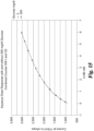
- FIG. 15 illustrates the aqueous dose response of a test sensor that includes two reagent layers, such as reagent layer 1302 and reagent layer 1304, wherein reagent layer 1302 is positioned on a working electrode and reagent layer 1304 is positioned on a combined counter/reference electrode as illustrated in FIG. 12 .
- reagent layer 1302 is configured for testing for the analyte, 3-hydroxybutric acid (ketone bodies), and reagent layer 1304 is configured for testing for the analyte, glucose, in the presence of two different concentrations of glucose.
- the first concentration of glucose is 0 mg/dl and the second concentration of glucose is 300 mg/dl.
- the graph in FIG. 15 demonstrates the absence of interference between the two different reagent layers, such as reagent layer 1302 and reagent layer 1304.
- Example A the actual spreading of the wet films upon application of a vacuum is measured and displayed graphically in FIG. 16 .
- the slot die shim used in the testing had a width W1 of the first channel 120 of 800 ⁇ m, the width W2 of the second channel 122 was 1550 ⁇ m, and the width W3 of the third channel 124 was 790 ⁇ m.
- the slot die shim also had a width W4 of the first divider wall 126 of 103 ⁇ m and the width W5 of the second divider wall 128 was 121 ⁇ m.
- the widths of the first, second, and third wet films and the widths of the first and second gaps were measured under an increasing vacuum force.
- the widths W11, W12, and W13 of the first, second, and third wet films were all less than the widths of their respective channels 120, 122, and 124.
- the widths W11 and W13 of the first and third wet films were greater than the widths W1 and W3 of their corresponding channels 120 and 124, and the width W12 of the second film was less than the width W2 of the second channel 122.
- the widths W11, W12, and W13 of the first, second, and third wet films were greater than the widths W1, W2, and W3 of the respective channels 120, 122, and 124.
- the width W14 of the first gap and the width W15 of the second gap were larger than the width W4 of the first divider wall 126 and the width W5 second divider wall 128, respectively.
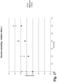
- the table "Relative Spreading” includes the ratio of the width of wet film to the corresponding width of the channel is determined at each vacuum pressure to determine the relative spreading of the wet film upon application of the vacuum. The results are displayed graphically in FIG. 17 . The table also determines the ratio of the width of the measured gap to the corresponding width of the divider wall.
- the widths W11, W12, and W13 of the first, second, and third wet films were all less than the widths of their respective channels 120, 122, and 124.
- the widths W11 and W13 of the first and third wet films were greater than the widths W1 and W3 of their corresponding channels 120 and 124, and the width W12 of the second film was less than the width W2 of the second channel 122.
- the widths W11, W12, and W13 of the first, second, and third wet films were greater than the widths W1, W2, and W3 of the respective channels 120, 122, and 124.
- the width W14 of the first gap and the width W15 of the second gap were larger than the width W4 of the first divider wall 126 and the width W5 of the second divider wall 128, respectively.
- the width W14 of the first gap was larger than the width W4 of the first divider wall 126 and the width W15 of the second gap was smaller than the width W5 of the second divider wall 128.
- the width W14 of the first gap and the width W15 of the second gap were each larger than the width W4 of the first divider wall 126 and the width W5 of the second divider wall 128, respectively.
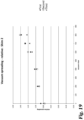
- the table "Relative Spreading” includes the ratio of the width of wet film to the corresponding width of the channel is determined at each vacuum pressure to determine the relative spreading of the wet film upon application of the vacuum. The results are displayed graphically in FIG. 19 .
- Example C the actual spreading of the wet films upon application of a vacuum is measured and displayed graphically in FIG. 20 .
- the slot die shim used in the testing had a width W1 of the first channel 120 of 825 ⁇ m, the width W2 of the second channel 122 was 1550 ⁇ m, and the width W3 of the third channel 124 was 810 ⁇ m of the slot die shim.
- the width W4 of the first divider wall 126 was 169 ⁇ m and the width W5 of the second divider wall 128 was 167 ⁇ m.
- the widths of the first, second, and third wet films and the widths of the first and second gaps were measured under an increasing vacuum force.
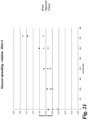
- the table "Relative Spreading” includes the ratio of the width of wet film to the corresponding width of the channel is determined at each vacuum pressure to determine the relative spreading of the wet film upon application of the vacuum. The results are displayed graphically in FIG. 21 .
Landscapes
- Chemical & Material Sciences (AREA)
- Life Sciences & Earth Sciences (AREA)
- Health & Medical Sciences (AREA)
- Organic Chemistry (AREA)
- Engineering & Computer Science (AREA)
- Zoology (AREA)
- Wood Science & Technology (AREA)
- Proteomics, Peptides & Aminoacids (AREA)
- Molecular Biology (AREA)
- Biochemistry (AREA)
- Immunology (AREA)
- General Health & Medical Sciences (AREA)
- Biophysics (AREA)
- Analytical Chemistry (AREA)
- Physics & Mathematics (AREA)
- Bioinformatics & Cheminformatics (AREA)
- Biotechnology (AREA)
- General Engineering & Computer Science (AREA)
- Microbiology (AREA)
- Genetics & Genomics (AREA)
- Emergency Medicine (AREA)
- Hematology (AREA)
- Chemical Kinetics & Catalysis (AREA)
- Electrochemistry (AREA)
- General Physics & Mathematics (AREA)
- Pathology (AREA)
- Coating Apparatus (AREA)
Description
- To assay multiple analytes on a single test element, or assay a single analyte with multiple reagents on a single test element, reagents are applied to different discrete areas of the test element. Such a test element, for example, is known from
US 2015/0076004 A1 . One technique of dispensing reagents onto a substrate of the test element includes ink jet application of the reagents. Ink jet application of reagents can create accurate reagent patterns on the substrate; however, the ink jet application is limited by the viscosity of the reagent liquid that can be applied by the ink jet. Typically ink jet application of reagents requires a low viscosity for the reagents for proper placement. As such, ink jet application typically does not apply reagents with a high viscosity. Another difficulty with the ink jet application is controlling the area and the profile of the reagent that is applied to a substrate. - Another technique of dispensing reagents onto a substrate includes slot die coating techniques as for example described in
US 3,413,143 . A slot die coating head is placed in close proximity to the substrate and dispenses a contiguous reagent film onto the substrate. The reagent film placed with the slot die coating head can cover a wide area on the substrate. However, the slot die coating head does not
allow for placement of multiple reagent films within a small area on the substrate. The slot die coating head can be fabricated by machining channels for multiple reagents directly into the head, but this arrangement would provide limited flexibility and re-use opportunity for alternative configurations of the reagents. Any change in the desired dimensions or separation of the channels in the slot die coating head would require remanufacture of the entire slot die coating head which is costly and time consuming. - In an alternative technique, the slot die coating head can include a thin shim placed therein. The shim can include openings for reagents to flow onto the substrate when the slot die coating head is placed in close proximity to the substrate.
- Such die-coating apparatuses with at least one shim are known from
US 6,159,544 A ,US 2006/0060135 A1 ,US 2003/0097981 A1 ,US 4,476,165 andUS 2012/0027942 . A similar concept for a micro-extrusion printhead 90 with alayered nozzle structure placed between a front and back plate structure is known fromUS 2013/0133201 A1 . - One shortcoming to the thin shim having two openings is that the openings must be positioned relatively far apart for the shim to have the required structural integrity and strength for the portion of the shim between the openings. With the openings being placed relatively far apart, the corresponding reagent films are also placed far apart on the substrate. A wider distance between the reagent films can also require a larger bodily fluid sample size to cover the two reagent areas. The
openings in the shim also dispense and form a thicker layer of reagent on the substrate that can therefore require a larger bodily fluid sample size to wet the reagent layer. Thicker reagent layers with a large gap distance between the layers can lead to spreading and mixing of the reagent layers, which may affect any test results. Moreover, it is even more problematic to include more than two openings and maintain the structural integrity of such thin shims, as well as maintain a workable distance among the corresponding reagent films placed on the substrate. - Thus, there is a need for improvement in this field.
- One aspect concerns a method for applying a plurality of wet films to a substrate as in
claim 4, another aspect concerns providing a slot die apparatus as inclaim 1, in particular, a slot die having a slot die shim positioned near a discharge end of the slot die, the slot die shim having a plurality of channels, applying a plurality of coatings through the plurality of channels, and dispensing the plurality of coatings simultaneously onto the substrate. - Further forms, objects, features, aspects, benefits, advantages, and embodiments of the present invention will become apparent from a detailed description and drawings provided herewith.
-
-
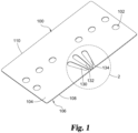
FIG. 1 is a perspective view of a slot die shim according to one embodiment. -
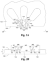
FIG. 2A is an enlarged view of a portion of theFIG. 1 slot die shim as taken along line 2-2 inFIG. 1 . -
FIG. 2B is a front view of theFIG. 2A portion of the slot die shim. -
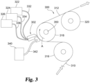
FIG. 3 is a diagrammatic illustration of a slot die coating apparatus. -
FIG. 4 is an enlarged view of a slot die assembly of theFIG. 3 apparatus. -
FIG. 5 is a front view of theFIG. 4 slot die assembly with a slot die shim facing the direction of coating flow. -
FIG. 6 is a cross-sectional view of theFIG. 5 slot die assembly. -
FIG. 7 is theFIG. 5 slot die assembly wherein the slot die shim is positioned in an orientation that is facing away from the direction of coating flow. -
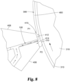
FIG. 8 is a cross-sectional view of theFIG. 7 slot die assembly. -
FIG. 9 is a diagrammatic illustration of a vacuum supply system configured to be coupled with theFIG. 4 slot die assembly. -
FIG. 10 is a diagrammatic illustration of a system for controlling operation of the slot die coating apparatus ofFIG. 3 and vacuum supply system ofFIG. 9 . -
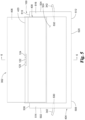
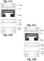
FIG. 11 is a schematic representation in two steps (A-B) how two electrochemical test elements with three reagent zones having a first gap configuration are manufactured using the slot-die coating process of the present application. -
FIG. 12 is a schematic representation in two steps (A-B) how two electrochemical test elements with three reagent zones having a second gap configuration are manufactured using the slot-die coating process of the present application. -
FIG. 13 is a schematic representation in two steps (A-B) how two electrochemical test elements with three reagent zones without gaps between the reagent zones are manufactured using the slot-die coating process of the present application. -
FIG. 14 is a schematic representation of a side view of a substrate material on which a first wet coating film, a second wet coating film, and a third wet coating film have been formed. -
FIG. 15 shows the dose-response results of an electrochemical test element with two reagents. -
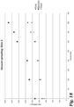
FIG. 16 is a graph of the actual spreading of a first wet film, a second wet film, and a third wet film applied to a substrate upon application of a vacuum with the use of a first slot die shim. -
FIG. 17 is a graph of ratios of the width of the wet film to the corresponding width of the channel at each vacuum pressure fromFIG. 16 . -
FIG. 18 is a graph of the actual spreading of a first wet film, a second wet film, and a third wet film applied to a substrate upon application of a vacuum with the use of a second slot die shim. -
FIG. 19 is a graph of ratios of the width of the wet film to the corresponding width of the channel at each vacuum pressure fromFIG. 18 . -
FIG. 20 is a graph of the actual spreading of a first wet film, a second wet film, and a third wet film applied to a substrate upon application of a vacuum with the use of a third slot die shim. -
FIG. 21 is a graph of ratios of the width of wet film to the corresponding width of the channel floor at each vacuum pressure fromFIG. 20 . - For the purpose of promoting an understanding of the principles of the invention, reference will now be made to the embodiments illustrated in the drawings and specific language will be used to describe the same. It will nevertheless be understood that no limitation of the scope of the invention is thereby intended. Any alterations and further modifications in the described embodiments, and any further applications of the principles of the invention as described herein are contemplated as would normally occur to one skilled in the art to which the invention relates. One embodiment of the invention is shown in great detail, although it will be apparent to those skilled in the relevant art that some features that are not relevant to the present invention may not be shown for the sake of clarity.
-
FIG. 1 shows a perspective view of a slot dieshim 100. Theslot die shim 100 is configured for use with a slotdie coating apparatus 300 described in more detail below. Theslot die shim 100 includes a plurality ofholes 102 that are arranged and configured to enable attachment of theslot die shim 100 to the slotdie coating apparatus 300. In particular, the slot dieshim 100 is positioned in a slot dieassembly 302. The slot dieshim 100 is bolted or attached through the plurality ofholes 102 when the slot dieshim 100 is assembled with the slot dieassembly 302. The slot dieshim 100 can be attached or assembled with the slot dieassembly 302 with other forms or mechanisms of attachment in other embodiments. - The slot die
shim 100 has a rectangular configuration in the illustrated embodiment but can be shaped differently in other embodiments. The slot dieshim 100 has a thickness T that spans between atop face 104 and abottom face 106. The slot dieshim 100 includes afirst channel 120, asecond channel 122, and athird channel 124. The slot dieshim 100 has afront face 108 opposite aback face 110 wherein thetop face 104 and thebottom face 106 span between thefront face 108 and theback face 110. - The slot die
shim 100 includes at least two channels. In one form, the slot dieshim 100 includes only two channels. In another form, the slot dieshim 100 includes four or more channels. Additionally, the channels can be arranged to coordinate with the location and orientation of one or more electrodes onsubstrate material 312 for placement of one or more coatings on the substrate as described in more detail below. In one illustrated embodiment, and as shown inFIG. 2A , the slot dieshim 100 includes thefirst channel 120, thesecond channel 122, and thethird channel 124 that extend through thetop face 104 towards thebottom face 106. None of thefirst channel 120, thesecond channel 122, or thethird channel 124 extends through thebottom face 106. As such, the thickness T of the slot dieshim 100 is sufficient for thefirst channel 120, thesecond channel 122, and thethird channel 124 to be cut or formed therein. There are many techniques in which thefirst channel 120, thesecond channel 122, and thethird channel 124 are formed in thetop face 104. Some of these techniques include cutting, etching, laser cutting, machining, or other techniques in which removal of material from thetop face 104 of the slot dieshim 100 forms thefirst channel 120, thesecond channel 122, and thethird channel 124. - The
first channel 120 will be described next. Thefirst channel 120 has afirst dispensing portion 140 that forms a length L1 of thefirst channel 120 and afirst application portion 142 that forms a length L2 of thefirst channel 120. Together the length L1 and the length L2 form the total length of thefirst channel 120. Thefirst dispensing portion 140 and thefirst application portion 142 can be arranged in any orientation relative to each other that enables fluid connectivity and fluid delivery of the first coating through thefirst channel 120. For example, thefirst application portion 142 can be arranged at an angle relative to thefirst dispensing portion 140 or thefirst application portion 142 can be aligned with thefirst dispensing portion 140. As another example, thefirst application portion 142 can have a radius of curvature and thefirst dispensing portion 140 can be straight. In one form, the length L1 of thefirst dispensing portion 140 is between about 0.2 millimeters to about 0.8 millimeters and thefirst application portion 142 has a radius of curvature R1 of between about 8 millimeters to about 20 millimeters. Thefirst dispensing portion 140 is arranged in a parallel or substantially parallel relationship to asecond dispensing portion 160 of thesecond channel 122 and parallel to athird dispensing portion 182 of thethird channel 124. Thefirst dispensing portion 140 includes afirst dispensing edge 144 that spans across the width W1 of thefirst channel 120. In the illustrated embodiment, thefirst dispensing edge 144 spans across thefront face 108. In another form, thefirst dispensing edge 144 is positioned near thefront face 108 to create a step with thefront face 108. - As shown in
FIG. 2B , thefirst channel 120 includes afirst channel wall 146, asecond channel wall 148, and a channel floor 150 that span from thefirst dispensing portion 140 through thefirst application portion 142 to fluidly connect with the firstfluid conduit opening 130. Thefirst channel wall 146 has a height H1 that spans from the channel floor 150 to thetop face 104. Thesecond channel wall 148 has a height H2 that spans from the channel floor 150 to thetop face 104. Thefirst channel 120 has a channel depth that corresponds to either the height H1 of thefirst channel wall 146 or the height H2 of thesecond channel wall 148, whichever is smaller. In one form, the channel depth is between about 0.1 millimeters to about 0.2 millimeters and in one form is 0.127 millimeters. Thefirst channel 120 has a width W1 that spans between thefirst channel wall 146 and thesecond channel wall 148 and across the channel floor 150. The width W1 is between about 0.5 millimeters and about 1.0 millimeters. Moreover the width W1 can be constant or vary along the length L1 and the length L2 of thefirst channel 120. As illustrated, the cross-sectional shape of thefirst channel 120 is u-shaped. When the first coating is dispensed through thefirst dispensing portion 140 onto the substrate, the width of the first coating corresponds to the width W1 of the channel floor 150 at thefirst dispensing edge 144. As discussed in more detail below, the width and thickness of the first coating on the substrate is further controlled or modified by the slot diecoating apparatus 300. - The
second channel 122 will be described next. As shown inFIG. 2A , thesecond channel 122 has thesecond dispensing portion 160 that forms a length L3 of thesecond channel 122 and asecond application portion 162 that forms a length L4 of thesecond channel 122. Together the length L3 and the length L4 form the total length of thesecond channel 122. Thesecond dispensing portion 160 and thesecond application portion 162 can be arranged in any orientation relative to each other that enables fluid connectivity and fluid delivery of the second coating through thesecond channel 122.FIG. 2A further illustrates thesecond dispensing portion 160 aligned with thesecond application portion 162. In one form, the length L3 of thesecond dispensing portion 160 is between about 0.2 millimeters to about 0.8 millimeters and the length L4 of thesecond application portion 162 is between about 5 millimeters to about 20 millimeters.FIG. 2B shows that thesecond dispensing portion 160 includes asecond dispensing edge 164 that spans across the width W2 of thesecond channel 122. In the illustrated embodiment, thesecond dispensing edge 164 spans across thefront face 108. In another form, thesecond dispensing edge 164 is positioned near thefront face 108 to create a step with thefront face 108. Thesecond dispensing edge 164 is arranged in a parallel or substantially parallel relationship to thefirst dispensing edge 144 of thefirst channel 120 and to athird dispensing edge 184 of thethird channel 124. - The
second channel 122 includes afirst channel wall 176, asecond channel wall 178, and achannel floor 180 that span from thesecond dispensing portion 160 through thesecond application portion 162 to fluidly connect with the secondfluid conduit opening 132. Thefirst channel wall 176 has a height H3 that spans from thechannel floor 180 to thetop face 104. Thesecond channel wall 178 has a height H4 that spans from thechannel floor 180 to thetop face 104. Thesecond channel 122 has a channel depth that corresponds to either the height H3 of thefirst channel wall 176 or the height H4 of thesecond channel wall 178, whichever is smaller. The channel depth ranges from about 0.1 millimeters to about 0.2 millimeters. The channel depth of thesecond channel 122 may be the same or different from the channel depth of thefirst channel 120. Thesecond channel 122 has a width W2 that spans between thefirst channel wall 176 and thesecond channel wall 178. In one form, the width W2 is between about 1.0 millimeters and about 2.0 millimeters. In another form, the width W2 is 1.65 millimeters. The width W2 can be constant or vary along the length L3 and the length L4. The width W2 of thesecond channel 122 is larger than the width W1 of thefirst channel 120. In one form, the width W2 is about twice as large as the width W1. When the second coating is dispensed through thesecond dispensing portion 160 onto the substrate, the width of the second coating corresponds to the width W2 of thechannel floor 180 at thesecond dispensing edge 164. As discussed in more detail below, the width and thickness of the second coating on the substrate is further controlled or modified by the slot diecoating apparatus 300. - The
third channel 124 is similar to thefirst channel 120 and thesecond channel 122. InFIG. 2A , thethird channel 124 is a mirror image of thefirst channel 120; therefore, similar details will not be described. In other forms, thethird channel 124 can be configured differently. -
FIG. 2B shows that the slot dieshim 100 also includes afirst divider wall 126 positioned between thefirst channel 120 and thesecond channel 122. The slot dieshim 100 includes asecond divider wall 128 positioned between thesecond channel 122 and thethird channel 124. Thefirst divider wall 126 and thesecond divider wall 128 extend from thetop face 104 to thebottom face 106. Thefirst divider wall 126 has a front face width W4 and thesecond divider wall 128 has a front face width W5 as measured along thefront face 108. The width of thefirst divider wall 126 and the width of thesecond divider wall 128 increase as thewalls front face 108 towards a first fluid conduit opening 130, a second fluid conduit opening 132, and a thirdfluid conduit opening 134. - When a first coating is dispensed through the
first channel 120 and a second coating is dispensed through thesecond channel 122, the front face width W4 corresponds to the gap width that is initially provided between the first coating and the second coating. Similarly, when the second coating is dispensed through thesecond channel 122 and a third coating is dispensed through thethird channel 124, the front face width W5 corresponds to the gap width that is initially provided between the second coating and the third coating. In one form, the front face width W4 and front face width W5 are between about 0.1 millimeters to about 0.5 millimeters. As discussed in more detail below, the gap width between the first and the second coatings on the substrate and the gap width between the second and the third coatings on the substrate are further controlled or modified by the slot diecoating apparatus 300. - Returning to
FIG. 1 , the slot dieshim 100 includes a first fluid conduit opening 130, a second fluid conduit opening 132, and a third fluid conduit opening 134 wherein the first, second, and thirdfluid conduit openings first channel 120, a second coating into thesecond channel 122, and a third coating into thethird channel 124. - Example dimensions and configurations A1, A2, and A3 for the
first channel 120, thesecond channel 122, thethird channel 124, thefirst divider wall 126, and thesecond divider wall 128 are provided in the following Table A. These dimensions and configurations are examples only and not intended to limit alternative configurations. All dimensions are measured in millimeters, unless noted otherwise.Table A Channel 120 Channel 122Channel 1241st Divider Wall 1262nd Divider Wall 128W1 R1 L1 H1 H2 W2 L2 H3 H4 W3 R3 L3 H5 H6 W4 W5 T A1 0.80 12.965 0.50 0.127 0.127 1.55 0.50 0.127 0.127 0.80 12.965 0.50 0.127 0.127 0.10 0.10 0.381 A2 0.80 13.263 0.50 0.127 0.127 1.55 0.50 0.127 0.127 0.80 13.263 0.50 0.127 0.127 0.18 0.18 0.381 A3 0.80 13.423 0.50 0.127 0.127 1.192 0.50 0.127 0.127 0.80 13.423 0.50 0.127 0.127 0.40 0.40 0.381 - The slot die shim is configured to simultaneously dispense the first coating through the
first channel 120, the second coating through thesecond channel 122, and the third coating through thethird channel 124 onto the substrate by methods, processes, and techniques of the slot diecoating apparatus 300 as described next. Other details regarding methods, processes, and techniques of the slot die coating apparatus are found inU.S. Pat. No.8,771,793 . - Referring to
FIG. 3 , there is illustrated the slot diecoating apparatus 300 configured to apply a first coating material (not illustrated), a second coating material 306 (seeFIG. 6 for example), and a third coating material (not illustrated) to aweb 310 ofsubstrate material 312 from which a plurality of test elements are obtained. The first coating material includes the first reagent for producing a first electrochemical signal in the presence of a first test analyte, thesecond coating 306 includes a second reagent for producing a second electrochemical signal in the presence of a second test analyte, and the third coating material includes the third reagent for producing a third electrochemical signal in the presence of a third test analyte. The first reagent, second reagent, and the third reagent can be the same reagent or different reagents or any combination of reagents as described in more detail below. -
Apparatus 300 includes afirst roller 316, asecond roller 318, and athird roller 320 through whichweb 310 is fed. For example,second roller 318 is rotated in a clockwise direction as indicated by arrow A asweb 310 is fed throughapparatus 300.Apparatus 300 also includes the slot dieassembly 302 positioned adjacent tosecond roller 318, afirst reservoir 322, asecond reservoir 324, and athird reservoir 326 fluidly coupled with slot dieassembly 302 respectively by afirst conduit 332, asecond conduit 334, and athird conduit 336. Thefirst reservoir 322 is configured to hold a quantity of the first coating material. Thesecond reservoir 324 is configured to hold a quantity of thesecond coating material 306. Thethird reservoir 326 is configured to hold a quantity of the third coating material. In some forms, thefirst reservoir 322, thesecond reservoir 324, and/or thethird reservoir 326 can be fluidly coupled to more than one channel in the slot dieshim 100 to supply the same coating material to more than one channel. In one form, in the "EXAMPLES" section of the subject document, thefirst reservoir 322 is fluidly coupled to both thefirst channel 120 and thethird channel 124 of the slot dieshim 100 and thesecond reservoir 324 is fluidly coupled to thesecond channel 122.Apparatus 300 also includes avacuum system 340 coupled with slot dieassembly 302 byconduits 342, only one of which is illustrated inFIG. 3 . Further details of these features will be provided below in connection withFIGS. 4-8 . - The slot die
assembly 302 includes aslot die head 402, the slot dieshim 100 attached to the slot diehead 402, and ahousing 404 that cooperates with slot diehead 402 and to whichvacuum system 340 is coupled as will be discussed below. Slot diehead 402 includes a coating dieupper section 406 positioned opposite of a coating dielower section 408. A first arrangement of slot dieshim 100 positioned in slot diehead 402 illustrated inFIGS. 5 and6 shows the slot dieshim 100 is positioned facing the direction of coating flow. A second arrangement of slot dieshim 100 positioned in slot diehead 402 illustrated inFIGS. 7 and8 shows the slot dieshim 100 is positioned in an orientation that is facing away from the direction of coating flow. Either configuration of the slot dieshim 100 will enable application of the first coating material, thesecond coating material 306, and the third coating material to theweb 310 ofsubstrate material 312. Some considerations in positioning the slot dieshim 100 in the slot diehead 402 include the direction of flow for the first coating material, thesecond coating material 306, and the third coating material relative to the direction of travel of theweb 310, and the position of thefirst channel 120, thesecond channel 122, and thethird channel 124 relative to the slot diehead 402. - The slot die
head 402 includes adischarge end 410 that includes a generallyplanar surface 412 on coating dieupper section 406 facingweb 310 and a generallyplanar surface 414 on coating dielower section 408 facingweb 310. InFIG. 6 ,surface 414 is offset towardweb 310 relative to surface 412, and inFIG. 8 ,surface 412 is offset towardweb 310 relative to surface 414, although other forms in which surfaces 412, 414 are even or offset in a different orientation relative towardweb 310 are also contemplated. Aslot 420 is formed between coating dieupper section 406 and coating dielower section 408 and opens through slot diehead 402 adjacent tosurfaces Slot 420 is sized to receive the slot dieshim 100 and either or both of the coating dieupper section 406 and/or the coating dielower section 408 can be configured to retain the slot dieshim 100 with bolts or other fastening devices through the plurality ofholes 102 in the slot dieshim 100. In one form (not illustrated), the coating dieupper section 406 and the coating dielower section 408 include holes that align with the plurality ofholes 102 in the slot dieshim 100 for attachment of the slot dieshim 100 between both the coating dieupper section 406 and the coating dielower section 408. Other forms of attaching the slot dieshim 100 with the slot diehead 402 can be used. InFIG. 6 , the slot dieshim 100 is positioned on the coating dielower section 408 such that thefront face 108 of the slot dieshim 100 is aligned withsurface 414. InFIG. 8 , the slot dieshim 100 is positioned on the coating dielower section 408 such that thefront face 108 of the slot dieshim 100 is aligned withsurface 412. Alternatively, the slot dieshim 100 is positioned on the coating dielower section 408 such that at least one of thefirst dispensing edge 144, thesecond dispensing edge 164, and thethird dispensing edge 184 is substantially aligned with one of thesurfaces - In the illustrated embodiment in
FIG. 4 , thefirst conduit 332, thesecond conduit 334, and thethird conduit 336 are connected to the coating dielower section 408 which is configured to retain and align theconduits second coating material 306, and the third coating material to be passed through slot diehead 402 and thechannels web 310, which is positioned betweensecond roller 318 and slot diehead 402. In one form, coating dieupper section 406 and coating dielower section 408 may be adjustably movable relative to one another to allow changes to the dimensions ofslot 420 positioned therebetween and the orientation of the slot dieshim 100 relative to the coating dieupper section 406 and the coating dielower section 408. Further, in other non-illustrated forms, coating dieupper section 406 or coating dielower section 408 may include a drip bib coupled therewith. - Turning now to
housing 404, it includes a pair of oppositely positionedlateral side panels 502, 504 (illustrated inFIG. 5 ), withside panel 502 extending between afirst end 506 and asecond end 508 andside panel 504 extending between afirst end 510 and asecond end 512. As illustrated inFIGS. 3 and4 for example,side panel 502 includes a concavely shapedsurface 514 extending betweenfirst end 506 andsecond end 508. In addition,side panel 504 also includes asurface 516 extending betweenfirst end 510 andsecond end 512 that is concavely shaped similar tosurface 514. The concavity ofsurfaces second roller 318 such thatside panels second roller 318. However, in other non-illustrated forms, different configurations forsurfaces FIG. 5 for example, a portion of coating dielower section 408 is positioned betweenside panels upper section 406 and all of coating dielower section 408 are positioned betweenside panels slot 420 is also positioned betweenside panels cross member 520 extends betweenside panels housing 404 facingsecond roller 318, and aback panel 522 extends betweenside panels cross member 520 can include a recessed portion through whichweb 310 extends as it is moved alongsecond roller 318.Cross member 520 may also include portions on opposite sides of the recessed portion, when present, which can be positioned against or in close proximity tosecond roller 318. -
Side panels cross member 520 can be positioned in close proximity withsecond roller 318 such that a generally enclosed environment orchamber 524 is provided upstream fromslot 420 and slot dieshim 100. Further, as will be explained in greater detail below, surfaces 412, 414 of slot diehead 402 andfront face 108 of slot dieshim 100 are positioned in relatively close proximity toweb 310. Similarly, this arrangement of slot diehead 402 and slot dieshim 100 relative toweb 310, as well as the discharge of first coating material from thefirst channel 120, thesecond coating material 306 from thesecond channel 122, and the third coating material from thethird channel 124, generally encloses or sealschamber 524 adjacent to first ends 506, 510 ofside panels second coating material 306, and third coating material are applied toweb 310. It should be appreciated thatchamber 524 is generally enclosed or sealed from the surrounding environment when the first coating material, thesecond coating material 306, and the third coating material are applied toweb 310. It should be appreciated that it is not necessary forchamber 524 to be entirely sealed from the surrounding environment, although forms in which it is sealed in such a manner are also contemplated. Rather, it is generally sufficient forchamber 524 to be sealed or enclosed from the surrounding environment in a manner that allows air pressure withinchamber 524 to be controlled relative to the surrounding environment, further details of which will be provided below. In one form for example,housing 404 can be positioned relative tosecond roller 318 such that a gap between about 5 µm and 250 µm extends betweensecond roller 318 and surfaces 514, 516. Forms in whichhousing 404 is positioned in contact withsecond roller 318 are also contemplated. -
Housing 404 also includes a pair of oppositely positionedoutlets chamber 524 opposite of one another and upstream from slot diehead 402. In the illustrated form,outlets conduits 342 withvacuum system 340 that is operable to regulate air pressure inchamber 524. For example,FIG. 9 illustrates a diagrammatic illustration of one non-limiting form forvacuum system 340 that can be utilized for regulating air pressure inchamber 524.Vacuum system 340 includes ablower 902 that is coupled in fluid communication with abaffle tank 904 by aconduit 906.Blower 902 is generally configured to pull air toward it and away frombaffle tank 904 to create a vacuum. In other non-illustrated forms, it is contemplated that the vacuum can be created using a pump or other sources in addition to or in lieu ofblower 902.Conduits 342 extend frombaffle tank 904 and are coupled withoutlets housing 404. Similarly, the vacuum applied to baffletank 904 byblower 902 is transferable frombaffle tank 904 throughconduits 342 tochamber 524.System 340 also includes aconduit 908 that is coupled with and extends between a drain outlet ofhousing 404 and adrain tank 910 and is operable to drain any liquid that may collect inhousing 404. -
System 340 further includes aflow control valve 912 that is positioned betweenblower 902 andbaffle tank 904 and in communication with the vacuum force present inconduit 906 whenblower 902 is operating. Abreather 914 is positioned adjacent to flowcontrol valve 912 and is operable to allow ambient air intoconduit 906 in response to certain operations offlow control valve 912. For example, in one form,vacuum system 340 may include one or more sensors configured to determine the strength or level of the vacuum force inconduit 906,baffle tank 904 orchamber 524, just to provide a few non-limiting possibilities, and flowcontrol valve 912 may be responsive to the one or more sensors to adjust the amount of ambient air allowed intoconduit 906 to adjust the level of the vacuum force ofsystem 340. In this or other forms,system 340 may also include one or more controllers, such as a frequency inverter driver, configured to control the operation ofblower 902 such that the amount or force of the vacuum created byblower 902 is adjusted in response to the vacuum levels measured by the one or more sensors. As indicated above, the illustrated form ofvacuum system 340 is non-limiting, and it should be further appreciated that other forms and arrangements are possible and contemplated forsystem 340. - Referring again to
FIG. 6 , further details regarding the application of first coating material (not illustrated),second coating material 306, and third coating material (not illustrated) toweb 310 to respectively form a first wet film, a second wet film, and a third wet film thereon will now be provided. Similar details fromFIG. 6 are applicable to the embodiment illustrated inFIG. 8 . It should be appreciated thathousing 404 is not illustrated inFIGS. 6 and8 in order to enhance clarity. The following parameters and description are applicable to the application of first coating material,second coating material 306, and third coating material in the respective form of the first reagent material, asecond reagent material 460, and the third reagent material toweb 310. Similarly, it should be appreciated that alternative values for the process parameters discussed below may be applicable to the slot die coating technique described herein for use with other forms of first coating material,second coating material 306, and third coating material or upon the occurrence of other changes. In addition, it should also be appreciated that the below-described parameters may also change as the desired thickness T and width W (FIG. 13 ) of each of a firstwet film 602, a secondwet film 604, and a thirdwet film 606 changes from the values described below. -
Discharge end 410 of slot diehead 402 is positioned in close proximity toweb 310 such that a coating gap CG extends there between. In one non-limiting form, coating gap CG is between about 20 µm and about 600 µm. In another more particular form, coating gap CG is between about 40 µm and about 450 µm. Still, in another more particular form, coating gap CG is between about 40 µm and about 200 µm. For example, coating gap CG is 170 µm. However, it should be appreciated that alternative values for coating gap CG are possible and contemplated and can be affected by the rheology and weight of first coating material,second coating material 306, and third coating material, surface tension and speed ofweb 310, the radius ofsecond roller 318, the lengths of coating dieupper section 406 and coating dielower section 408 of slot diehead 402, inlet gap and length of slot diehead 402, and the angle, if any, of coating dieupper section 406 relative to the coating dielower section 408. Alternative values for the coating gap CG are also affected by the configuration of thefirst channel 120, thesecond channel 122, thethird channel 124, thefirst divider wall 126, and thesecond divider wall 128. The depth of thefirst channel 120, depth of thesecond channel 122, and depth of thethird channel 124 also affect the coating gap CG. - In one form,
slot 420 includes a width betweenside panels shim 100 to apply first coating material,second coating material 306, and third coating material through thefirst channel 120,second channel 122, and thethird channel 124. Theslot 420 also includes aheight 430 between coating dieupper section 406 and coating dielower section 408 that corresponds to the thickness T of the slot dieshim 100. For example,height 430 is between about 100 µm and about 500 µm. In one particular form, theheight 430 ofslot 420 is about 381 µm. As illustrated inFIG. 6 for example, slot diehead 402 generally extends orthogonally toweb 310 at the location wheredischarge end 410 is positioned adjacent thereto. However, in other forms it is also contemplated that slot diehead 402 can extend obliquely relative toweb 310. In addition, as best seen inFIG. 3 for example, slot diehead 402 is oriented at an oblique angle relative to acentral axis 350 ofsecond roller 318 which, in one form, can be between about 10 degrees and about 25 degrees, although other variations are also contemplated. - As indicated above,
web 310 is moved relative to slotdie assembly 302 by one or more offirst roller 316,second roller 318, andthird roller 320 ofapparatus 300. In one form,web 310 is moved relative to slotdie assembly 302 at a rate between about 35.0 m/min and about 45.0 m/min. In another more particular form,web 310 is moved relative to slotdie assembly 302 at a rate of about 10.0 m/min. Other variations for the rate at whichweb 310 is moved are contemplated depending on the desired width and thickness of each of the first coating material,second coating material 306, and third coating material relative to the particular application of the method and apparatus disclosed herein, and also depending on the flow rates of the discharged first coating material,second coating material 306, and third coating material. For example, in certain experimental coating processes described in greater detail below in the "EXAMPLES" section of the subject document, the web was moved relative to the slot die assembly at a rate between about 8.0 m/min and 12.0 m/min, and more particularly at a rate of about 10.0 m/min. - As
web 310 is moved relative to slotdie assembly 302, first coating material,second coating material 306, and third coating material are delivered to slot diehead 402 fromfirst reservoir 322,second reservoir 324, andthird reservoir 326, respectively, using, by way of non-limiting example, one or more pumps, pistons, syringes, or bladder systems for each of thereservoirs reservoirs second coating material 306, and third coating material can be applied at different flow rates. First coating material,second coating material 306, and third coating material are respectively forced through thefirst conduit 332, thesecond conduit 334, and thethird conduit 336 and into the slot diehead 402. Thefirst conduit 332, thesecond conduit 334, and thethird conduit 336 are respectively connected with the first fluid conduit opening 130, a second fluid conduit opening 132, and a third fluid conduit opening 134 to enable the first coating material,second coating material 306, and third coating material to flow into thefirst channel 120, thesecond channel 122, and thethird channel 124. The first coating material,second coating material 306, and third coating material exit thefirst channel 120, thesecond channel 122, thethird channel 124, and theslot 420 atdischarge end 410 where it is applied ontoweb 310 ofsubstrate material 312 to form firstwet film 602, secondwet film 604, and thirdwet film 606. As illustrated inFIG. 14 for example, firstwet film 602 includes a width W11 and a thickness T11, secondwet film 604 includes a width W12 and a thickness T12, and thirdwet film 606 includes a width W13 and a thickness T13 relative toweb 310. Also illustrated inFIG. 14 for example, is a first gap width W14 between the firstwet film 602 and the secondwet film 604 and a second gap width W15 between the secondwet film 604 and the thirdwet film 606. As discussed in more detail below, the width and thickness of the first, second, and third wet films and the widths of the first and second gap are controlled and modified by thevacuum system 340. - In one form, the discharge rates of first coating material,
second coating material 306, and third coating material from thefirst channel 120, thesecond channel 122, and thethird channel 124 at thedischarge end 410 are between about 10.0 mL/min and about 20.0 mL/min. In another more particular form, the discharge rates of first coating material,second coating material 306, and third coating material are between about 12.0 mL/min and about 18.0 mL/min. In another form, the discharge rates of first coating material,second coating material 306, and third coating material fromdischarge end 410 are between about 15.0 mL/min and about 18.0 mL/min. In any form, the discharge rates of first coating material,second coating material 306, and third coating material from thefirst channel 120, thesecond channel 122, and thethird channel 124 at thedischarge end 410 can be the same or vary from each other. For example, the discharge rate of the first and third coating materials can be the same and the discharge rate of thesecond coating material 306 can be different from the first and third coating materials. As another example, the discharge rate of thesecond coating material 306 can be about twice as fast as the discharge rates of the first and third coating materials. Still, other variations for the rate at which first coating material,second coating material 306, and third coating material are discharged fromdischarge end 410 are also contemplated, and can be dependent on, amongst other things, the desired width and thickness of the first coating material,second coating material 306, and third coating material relative to the particular application of the method and apparatus disclosed herein, and also on the rate at whichweb 310 is moved relative to slotdie head 402. For example, in certain experimental coating processes described in greater detail below in the "EXAMPLES" section of the subject document, the discharge rates of first, second, and third coating materials from thefirst channel 120, thesecond channel 122, and thethird channel 124 of the slot dieshim 100 in the slot diehead 402 was between about 0.5 mL/min and about 4.0 mL/min. In one form and in the "EXAMPLES" section of the subject document, the discharge rate of the second coating material from thesecond channel 122 was 0.843 mL/min and the discharge rate of the first and third coating materials from thefirst channel 120 and thethird channel 124, respectively, was 0.873 mL/min wherein the first and third coating materials were combined in thefirst reservoir 322. - In the illustrated example of
FIG. 14 , the targeted width W11 of the firstwet film 602 and the targeted width W13 of the thirdwet film 606 are substantially similar or the same and ranges between about 600 µm and 1500 µm. The targeted width W12 of the secondwet film 604 is larger than the targeted width W11 of the firstwet film 602. The targeted width W12 of the secondwet film 604 is larger than the targeted width W13 of the thirdwet film 606. The targeted width W12 of the secondwet film 604 ranges between about 900 µm and 1700 µm. Also illustrated inFIG. 14 for example is width W14 of a first gap between the firstwet film 602 and the secondwet film 604 and a width W15 of a second gap between the secondwet film 604 and the thirdwet film 606. The targeted width W14 of the first gap and the targeted width W15 of the second gap are substantially similar or the same and range between about 90 µm and 700 µm. However, it should be appreciated that alternative values for the targeted width W11 of the firstwet film 602, targeted width W12 of the secondwet film 604, the targeted width W13 of the thirdwet film 606, and the targeted width W14 of the first gap and the targeted width W15 of the second gap are also contemplated. Additional dimensions for the targeted width W11 and thickness T11 of the firstwet film 602, targeted width W12 and thickness T12 of the secondwet film 604, the targeted width W13 and thickness T13 of the thirdwet film 606, and the targeted width W14 of the first gap and the targeted width W15 of the second gap are provided in the "EXAMPLES" section of the subject document. -
FIGS. 6 and8 also illustrate that a first pressure P1 is present downstream of slot diehead 402 and that a second pressure P2 is present upstream from slot diehead 402. More particularly, first pressure P1 is indicative of ambient air pressure in theatmosphere surrounding apparatus 300, while second pressure P2 is indicative of air pressure inchamber 524 ofhousing 404. Whenvacuum system 340 applies a vacuum force tochamber 524, second pressure P2 is less than first pressure P1 and the difference between first pressure P1 and second pressure P2 defines a coating vacuum. In one form, the coating vacuum is between about 0 Pa and about 800 Pa. However, it should be appreciated that other values for the coating vacuum are contemplated and fall within the scope of the subject document. - One factor that can affect the widths and thicknesses of the
wet films second coating material 306, and third coating material upon exit of thefirst channel 120,second channel 122, andthird channel 124, respectively. Another factor that can affect the widths and thicknesses of thewet films second coating material 306, and third coating material through thefirst channel 120,second channel 122, andthird channel 124, respectively. It should be appreciated that the targeted widths W11, W12, and W13 and thicknesses T11, T12, and T13 ofwet films chamber 524 byvacuum system 340. Adjustments to the coating vacuum can be used to control in real time the targeted width W11 and thickness T11 of the firstwet film 602, targeted width W12 and thickness T12 of the secondwet film 604, the targeted width W13 and thickness T13 of the thirdwet film 606, the targeted width W14 of the first gap and the targeted width W15 of the second gap that will be applied toweb 310. Further, the ability to control thicknesses T11, T12, and T13 ofwet films wet films web 310. Similarly, each of the test elements obtained fromweb 310 will have a more uniform thickness T of each of the first reagent material, thesecond reagent material 460, and the third reagent material, thereby resulting in greater lot to lot consistency in the finished test elements. - At a low amount of vacuum force the width W11 of the first
wet film 602, width W12 of the secondwet film 604, and the width W13 of the thirdwet film 606 may each be respectively less than the width W1 of thefirst channel 120, the width W2 of thesecond channel 122, and the width W3 of thethird channel 124 as a result of other factors including but not limited to necking and flow rate. At a higher amount of vacuum force, the width W11 of the firstwet film 602, width W12 of the secondwet film 604, and the width W13 of the thirdwet film 606 may each be respectively greater than the width W1 of thefirst channel 120, the width W2 of thesecond channel 122, the width W3 of the third channel. In some forms, the vacuum force will change the width W11 of the firstwet film 602, width W12 of the secondwet film 604, and the width W13 of the third wet film 606 a different amount respectively to the width W1 of thefirst channel 120, the width W2 of thesecond channel 122, and the width W3 of thethird channel 124. For example, the vacuum force may alter the width W11 of the firstwet film 602 and the width W13 of the third wet film 606 a larger amount than the width W12 of the secondwet film 604. Generally, larger increases in the amount of vacuum force applied tochamber 524 byvacuum system 340 will generally result in increases to the targeted width W11 of the firstwet film 602, targeted width W12 of the secondwet film 604, and the targeted width W13 of the thirdwet film 606. As the targeted widths W11, W12, and W13 of thewet films wet films first channel 120,second channel 122, andthird channel 124 by increasing the vacuum force of thevacuum system 340. - One non-limiting approach for maintaining consistency and uniformity in widths W11, W12, and W13 and thicknesses T11, T12, and T13 of
wet films wet films system 1000 inFIG. 10 . More particularly,system 1000 includesapparatus 300, includingvacuum system 340, each of which has been described above.System 1000 also includes asensor 1100 for determining the widths W11, W12, and W13 ofwet films films web 310 byapparatus 300. In one form,sensor 1100 can be an optical sensor, such as a digital camera, although other forms forsensor 1100 are contemplated.Sensor 1100 is also operable to generate a sensor signal corresponding to the determined widths W11, W12, and W13 of thewet films first controller 1200. Afirst controller 1200 is programmed to determine if the widths W11, W12, and W13 of thewet films sensor 1100 correspond to a value other than a predetermined value or range of values and, if so, transmit a corresponding controller signal to asecond controller 1400 indicating the changes that must be made to the width W11 of the firstwet film 602, width W12 of the secondwet film 604, and the width W13 of the thirdwet film 606 in order to achieve a targeted thickness T11 of firstwet film 302, targeted thickness T12 of secondwet film 604, and targeted thickness T13 of thirdwet film 606 based on the following equation:
- By changing the widths W11, W12, and W13 of the
wet films wet film 602 and the thirdwet film 606 is from about 500 µm to about 1200 µm and the predetermined value for width W for secondwet film 604 is from about 1200 to about 1700 µm. In another form, the predetermined value for width W is 700 µm. In another variation, the predetermined value for width W of the secondwet film 604 is about twice as large as the predetermined value for width W of either the firstwet film 602 or the thirdwet film 606. For example, the predetermined value for width W for secondwet film 604 is about 9 µm to about 16 µm and the predetermined value for width W for first and thirdwet films wet films web 310 ofsubstrate material 312. However, it should be appreciated that other variations in the predetermined value or range of values for width W are possible. -
Second controller 1400 is generally programmed to control the amount of vacuum applied byvacuum system 340 in response to receiving from first controller 1200 a controller signal indicating that changes must be made to widths W11, W12, and W13 of thewet films vacuum sensor 1300 that is indicative that the actual amount of vacuum being applied tochamber 524 ofhousing 404 does not correspond to the amount of vacuum that should be applied thereto as determined bycontroller 1400. In view of the foregoing, it should be appreciated thatsystem 1000 can, by way of non-limiting example, automatically and in real-time control the widths W11, W12, and W13, and in turn thicknesses T11, T12, and T13, ofwet films web 310. More particularly, in the event any widths W11, W12, and W13 ofwet films sensor 1100 do not correspond to the predetermined value or range of values, then the amount of vacuum applied byvacuum system 340 will automatically be adjusted as appropriate to bring widths W11, W12, and W13 ofwet films wet films wet films web 310, which in the case of the first reagent material,second reagent material 460, and the third reagent material, results in greater consistency between the individual test elements that will be obtained from web 14 to whichwet films wet films - It has also been discovered that controlling the amount of vacuum applied to
chamber 524 can significantly adjust the widths W11, W12, and W13 and thicknesses T11, T12, and T13, ofwet films chamber 524 causes spreading or increasing of widths W11, W12, and W13 of thewet films wet films wet films channels wet films channels chamber 524 results in a more uniform thickness profile of the first reagent material,second reagent material 460, and the third reagent material across the widths of each of these reagent layers formed afterwet films - In addition, it should also be appreciated that adjusting the widths W11, W12, and W13 and thicknesses T11, T12, and T13, of
wet films chamber 524 also eliminates any need to move slot diehead 402 relative toweb 310 such that a constant coating gap CG can be maintained between said slot diehead 402 andweb 310 as first coating material,second coating material 306, and the third coating material are applied thereto. Furthermore, a constant flow rate of first coating material, thesecond coating material 306, and the third coating material through slot diehead 402 and a constant speed ofweb 310 relative to slotdie head 402 can also be maintained when the widths W11, W12, and W13 and thicknesses T11, T12, and T13 ofwet films chamber 524. Likewise, the approach described herein conveniently only requires a change to be made to a single process parameter in order to adjust the widths W11, W12, and W13 and thicknesses T11, T12, and T13 ofwet films - While not previously discussed, it should be appreciated that slot die
coating apparatus 300 and/orsystem 1000 can be provided with additional features useful forprocessing web 310 either before or after the formation ofwet films apparatus 300 also includes a dryer or drying mechanism that facilitates drying ofwet films second reagent material 460, and the third reagent material. In one aspect, the dried layers of the first reagent material,second reagent material 460, and the third reagent material each include a thickness relative tosubstrate material 312 between about 1 µm and about 20 µm, between about 3 µm and about 20 µm, or between about 2 µm and about 10 µm, although other values for the thicknesses of the dried layers of the first reagent material,second reagent material 460, and the third reagent material are also contemplated.Apparatus 300 may also include one or more cleaners or other components for preparing and/orprocessing web 310 for application of first coating material,second coating material 306, and the third coating material.Apparatus 300 may also include additional devices or components for preparing and/orprocessing web 310 to form a plurality of test elements. For example, additional rollers carrying webs that can form additional layers of material for the plurality of test elements can also be included. One or more cutting devices can also be included withapparatus 300 to cutweb 310 into the plurality of test elements following the formation and drying ofwet films web 310 and one or more of thewet films web 310 is cut by the cutting devices through the secondwet film 604 to form the plurality of test elements. In this embodiment, the width W12 of secondwet film 604 is sufficient to cover one or more electrodes on each of the plurality of test strips and thefirst film 602 is positioned on a first group of test strips and thethird film 606 is positioned on a second group of test strips wherein the first group of test strips does not include any test strips with thethird film 606 thereon. In one form, the test elements include a length between about 20 millimeters and about 50 millimeters and a width between about 5 millimeters and about 15 millimeters. In a more particular form, the test elements include a length between about 33 millimeters and about 38 millimeters and a width between about 7 millimeters and about 9 millimeters. - As indicated above, the foregoing description regarding the application of first coating material,
second coating material 306, and the third coating material has been made in connection with the formation of firstwet film 602 of the first reagent material, secondwet film 604 ofsecond reagent material 460, and thirdwet film 606 of the third reagent material onweb 310 ofsubstrate material 312 from which a plurality of test elements will be obtained. Once formed, the test elements can be used in a system that is useful for assessing a different analyte for each reagent material in a sample fluid. In one form, the analyte assessment may range from detecting the presence of the analyte to determining the concentration of the analyte. The analyte and the sample fluid may be any for which the test system is appropriate. By way of non-limiting example, one embodiment is described below in which a first analyte is glucose, a second analyte is ketone, and a third analyte is glucose and the sample fluid is blood or interstitial fluid. However, the assessment of other analytes in different sample fluids is also contemplated. - The test elements provide an electrochemical sensor including a sample-receiving chamber for the sample fluid, and any number of the first reagent material, second reagent material, and the third reagent material that are suitable for producing a first, second, and/or third electrochemical signal in the presence of the test analyte. In one example embodiment, a first test element can include the first reagent material and the second reagent material and a second test element can include the second reagent material and the third reagent material. In one form, the test elements are in the form of disposable test strips. The test elements are used in combination with a meter for determination of the analyte in the sample fluid. The meter conventionally includes a connection with electrodes on the test elements and circuitry to evaluate the electrochemical signal corresponding to the concentration of one or more analytes. The meter may also include means for determining that the sample fluid has been received by the test element and that the amount of sample fluid is sufficient for testing. The meter typically will store and display the results of the analysis, or may alternatively provide the data to a separate device. It will be appreciated by those of skill in the art that optical sensors (i.e. sensors configured with reagent material to produce an optical signal in the presence of an analyte) may also be produced according to the teachings herein, analogously to electrochemical sensors.
- As indicated above, the foregoing description regarding the resultant width W14 of the first gap between the first
wet film 602 and the secondwet film 604 and the width W15 of the second gap between the secondwet film 604 and the thirdwet film 606 from which a plurality of test elements will be obtained each provide a region on an electrode without reagent material. Once formed, the test elements can also be used in a system that is useful or beneficial in some measurement methods for example such as impedance and capacitance for detecting a response to be used to correct for interfering variables such as temperature, hematocrit, and/or other potential electrochemically active species not associated with the analytes of interest. If the widths W14 and W15 of the gaps are nominal or almost zero, then the adjacent wet films are substantially in contact or touching each other and crossreactivity is typically reduced. Crossreactivity is whether or not a signal produced by a first analyte interferes with the signal of a second adjacent analyte. Crossreactivity is any phenomenon by which a signal from the first analyte creates an undesired effect on the second or any other analyte. As such, the crossreactivity deals with chemical interferences between the analytes. This can result in artificially elevated signals and presents a major issue when analyzing low signal samples adjacent to high signal samples. Surprisingly it was discovered that for some types of reagents such as reagents having high viscosity at low shear, two reagents positioned substantially in contact with each other on a test strip, i.e., no gap, have less crossreactivity than two reagents that have a small gap between them. Beneficially it was also discovered that for some types of reagents such as reagents having high viscosity at low shear, two reagents positioned substantially in contact with each other on a test strip, i.e., no gap, prevent diffusion, mixing, or spreading of the reagents. Examples of reagents with high viscosity at low shear include reagents with a viscosity of between about 95 to 115 mPa-s and a surface tension of between about 33 and 42 mN/m. Other formulations of reagents may have different properties. - It is contemplated that the test elements may be useful for the determination of a wide variety of analytes. For example, the test elements may be readily adapted for use with the first reagent material, second reagent material, and the third reagent material having any suitable chemistry that can be used to assess the presence of the analyte. In one specific form, the test elements are configured and used for the testing of one or more analytes in a biological fluid. Such analytes may include, for example, glucose, cholesterol, HDL cholesterol, triglycerides, lactates, lactate dehydrogenase, alcohol, uric acid, and ketone. As used herein, "ketone" means ketone bodies such as hydroxybutyrate, especially 3-hydroxybutric acid. Non-limiting examples of biological fluids in which the analyte can be assessed include any bodily fluid in which the analyte can be measured, such as interstitial fluid, dermal fluid, sweat, tears, urine, amniotic fluid, spinal fluid and blood. The term "blood" in the context of this document includes whole blood and its cell-free components, namely plasma and serum. When the test elements are configured for the testing of glucose, the sample fluid may specifically include, for example, fresh capillary blood obtained from the fingertip or approved alternate sites (e.g., forearm, palm, ear lobe, upper arm, calf and thigh), and fresh venous blood. In addition, the test elements may also be useful in connection with control fluids that are used in conventional fashion to verify the integrity of the system for testing.
- The bodily fluid containing the one or more analytes to be assessed may be acquired and delivered to the test elements in any fashion. For example, a blood sample may be obtained in conventional fashion by incising the skin, such as with a lancet, and then contacting the test element with fluid that appears at the skin surface. In one aspect, the test elements are operable for assessing the targeted analytes with only using very small fluid samples. Similarly, in one aspect, only a slight skin incision is necessary to produce the volume of fluid required for the test, and the pain and other concerns with such a method can be minimized or eliminated.
- The test elements which are formed from
web 310 on which the layers of the first reagent material,second reagent material 460, and the third reagent material are deposited include several basic components. More particularly, the test elements comprise a small body defining a chamber in which the sample fluid is received for testing. This "sample-receiving chamber" may be filled with the sample fluid by suitable means, such as by capillary action, but also optionally assisted by pressure or vacuum. The sample-receiving chamber includes electrodes and chemistry suitable for producing an electrochemical signal indicative of one or more analytes in the sample fluid. - Referring now to
FIGS. 11, 12 , and13 for example, a portion ofweb 310 is illustrated and includes a plurality ofelectrode systems 1300 a-f which will individually be included on separate test elements formed from the illustrated portion ofweb 310. Each of theelectrode systems 1300 a-f includes a plurality of electrodes and electrode traces which terminate in contact pads (not illustrated). Theelectrode systems 1300 a-f are arranged in a head-to-head or nose-to-nose configuration for manufacturing. Theelectrode systems 1300 a-f can be arranged in alternative configurations. A portion of alayer 1302 of the first reagent material overlies at least a portion of each of theelectrode systems 1300 a, c, e. A portion of alayer 1304 ofsecond reagent material 460 overlies a portion of each of theelectrode systems 1300 a-f. A portion of alayer 1306 of the third reagent material overlies a portion of each of theelectrode systems 1300 b, d, f. Similarly, it should be appreciated that the first reagent material,second reagent material 460, and the third reagent material are applied toweb 310 following the formation ofelectrode systems 1300 a-f thereon. As also illustrated inFIGS. 11, 12 , and13 ,reagent layers web 310 and across the correspondingelectrode systems 1300 a-f. In the illustrated embodiments, after theweb 310 is cut to form individual test strips, each of theelectrode systems 1300 a-f will include two reagent layers. For example,electrode systems 1300a, c, and e will each includereagent layer 1302 andreagent layer 1304.Electrode systems 1300b, d, and f will each include areagent layer 1306 andreagent layer 1304. In this embodiment,reagent layer 1304 covers portions of all of the electrode sets. In other configurations, any ofreagent layers - As mentioned above and illustrated in
FIGS. 11, 12 , and13 , the reagent layers 1302, 1304, and 1306 extend as narrow, substantially parallel, stripes along the length of the illustrated portion ofweb 310 and across the correspondingelectrode systems 1300 a-f. The reagent layers 1302 and 1304 form afirst gap 1312 that spans between thereagent layers web 310. The reagent layers 1304 and 1306 form asecond gap 1314 that spans between thereagent layers web 310. The width of each of the first andsecond gaps second gaps second gaps FIG. 13 . It should be appreciated that the largest widths of the first andsecond gaps FIG. 11 . Other embodiments can include a greater width of the first andsecond gaps second gaps electrode sets 1300 a-f that do not have reagent layers thereon. The widths of the reagent layers 1302, 1304, and 1306 and the widths of the first andsecond gaps electrode systems 1300 a-f onweb 310. - In
FIGS. 11, 12 , and13 , theelectrode sets 1300 a-f are arranged in a nose-to-nose configuration wherein each of theelectrode sets 1300 a-f includes a combined counter/reference electrode and a working electrode. In these embodiments, thereagent layers reagent layer 1304 is positioned on a combined counter/reference electrode. Other embodiments can include a different arrangement of electrode sets and a different arrangement or number of reagent layers. -
Substrate material 312 ofweb 310 is formed of an insulating material on whichelectrode systems 1300 a-f are positioned. Typically, plastics such as vinyl polymers, polyimides, polyesters, and styrenes provide the electrical and structural properties which are required. Further, because the test elements can be mass producible from rolls of material, it is desirable that the material properties be appropriate to have sufficient flexibility for roll processing, while also giving a useful stiffness to the finished element.Substrate material 312 can be selected as a flexible polymeric material such as polyester, including high temperature polyester materials; polyethylene naphthalate (PEN); and polyimide, or mixtures of two or more of these. Polyimides are available commercially, for example under the trade name Kapton®, from E.I. duPont de Nemours and Company of Wilmington, Del. (duPont). One specific possibility forsubstrate material 312 is MELINEX® 329 available from duPont. - The test elements are configured to detect the presence of, and/or measure the concentration of, one or more analytes by way of electrochemical oxidation and reduction reactions. These reactions are transduced to an electrical signal that can be correlated to an amount or concentration of the analyte. Similarly, the electrode system on each test element includes a set of measuring electrodes, e.g., at least a working electrode and a counter electrode, or a combined counter/reference electrode and a working electrode that are positioned within the sample-receiving chamber. The sample-receiving chamber is configured such that sample fluid entering the chamber is placed in electrolytic contact with both the working electrode and the counter electrode. This allows electrical current to flow between the measuring electrodes to affect the electrooxidation or electroreduction of the analyte.
- A "working electrode" is an electrode at which the analyte is electrooxidized or electroreduced with or without the agency of a redox mediator, while the term "counter electrode" refers herein to an electrode that is paired with the working electrode and through which passes an electrical current equal in magnitude and opposite in sign to the current passed through the working electrode. The term "combined counter/reference electrode" is meant to include counter electrodes which also function as reference electrodes (i.e., counter/reference electrodes).
- The counter and reference electrodes, and the remaining portions of the electrode system, may be formed from a variety of materials. In one aspect, the electrodes should have a relatively low electrical resistance and should be electrochemically inert over the operating range of the test elements. Suitable conductors for the working electrode include gold, palladium, platinum, carbon, titanium, ruthenium dioxide, indium tin oxide, and iridium, as well as others. The counter electrode may be made of the same or different materials, e.g., silver/silver chloride. In one specific embodiment, the counter and reference electrodes are both gold electrodes.
- The electrodes may be applied to
substrate material 312 in any fashion that yields electrodes of adequate conductivity and integrity. Exemplary processes include sputtering and printing, just to provide a few non-limiting possibilities. In one specific form, gold electrodes are provided bycoating substrate material 312 and then removing selected portions of the coating to yield the electrode system. One particular method for removing portions of the coating includes laser ablation or broad field laser ablation. - Laser ablative techniques typically include ablating a single metallic layer or a multilayer composition that includes an insulating material and a conductive material, e.g., a metallic-laminate of a metal layer coated on or laminated to an insulating material. The metallic layer may contain pure metals, alloys, or other materials, which are metallic conductors. Examples of metals or metallic-like conductors include: aluminum, carbon (such as graphite), cobalt, copper, gallium, gold, indium, iridium, iron, lead, magnesium, mercury (as an amalgam), nickel, niobium, osmium, palladium, platinum, rhenium, rhodium, selenium, silicon (such as highly doped polycrystalline silicon), silver, tantalum, tin, titanium, tungsten, uranium, vanadium, zinc, zirconium, mixtures thereof, and alloys or solid solutions of these materials. In one aspect, the materials are selected to be essentially unreactive to biological systems, non-limiting examples of which include gold, platinum, palladium, iridium, silver, or alloys of these metals or iridium tin oxide. The metallic layer may be any desired thickness which, in one particular form, is about 500 nm.
- The electrode system may have a variety of configurations suited to the operation of the test elements and corresponding meter. In one form, the counter and reference electrodes are positioned and dimensioned to minimize the volume of sample fluid required to cover them. In addition, the electrodes may also be configured to maintain a current flux of sufficient magnitude as to be measurable using a relatively inexpensive hand-held meter.
- The electrode traces and contact pads of the electrode system may be provided in a variety of fashions consistent with their intended function relative to the test element. These components of the electrode system may be composed of the same material as the electrodes, and are applied to the base substrate in the same manner and simultaneously with the application of the electrodes. In one specific embodiment, the traces and contact pads are gold, and are formed by laser ablation. However, alternate materials and methods of application may be employed.
- Each of the first reagent material,
second reagent material 460, and the third reagent material is operable to react with the test analyte to produce the electrochemical signal that represents the presence of the analyte in the sample fluid. The first reagent material,second reagent material 460, and the third reagent material can be configured to react with the same test analyte or different test analytes. For example, the first reagent material can react with a first test analyte andsecond reagent material 460 can react with a second test analyte wherein the first test analyte is different than the second test analyte. In one form, the first and the third reagent materials can react with the same test analyte andsecond reagent material 460 can react to a different test analyte. In another form, first and the third reagent materials can react with different test analytes. The first reagent material,second reagent material 460, and the third reagent material can include a variety of active components selected to determine the presence and/or concentration of various analytes. The test chemistry is therefore selected in respect to the analyte to be assessed. As is well known in the art, there are numerous chemistries available for use with each of various analytes. For example, in one particular form, the first reagent material,second reagent material 460, and the third reagent material can include one or more enzymes, co-enzymes, and co-factors, which can be selected to determine the presence of glucose in blood. In a more specific form where the analyte is glucose, the active components of the first reagent material,second reagent material 460, and the third reagent material will typically include an oxidoreductase, such as an enzyme for glucose; optionally a co-enzyme or co-factor; and a redox mediator. These components are typically dissolved or suspended in a matrix. The liquid test sample hydrates or dissolves the matrix, and the analyte diffuses through the matrix to react with one or more of the active components. Typically, the enzyme oxidizes the glucose in the test sample to gluconolactone and/or gluconic acid. The mediator, in turn, reacts with or oxidizes the reduced enzyme, and consequently the mediator is reduced in the process. The reduced mediator can be detected at one of the electrodes on the test strip. More specific details regarding a specific form of the first reagent material,second reagent material 460, and the third reagent material for determining the presence of glucose in blood are found inU.S. Pat. No. 7,727,467 and/orU.S. Pat. No. 7,879,6 18 . - In conventional fashion, the first reagent material,
second reagent material 460, and the third reagent material may include a variety of adjuvants to enhance various properties or characteristics thereof. See e.g.,U.S. Pat. No. 7,727,467 and/orU.S. Pat. No. 7,879,618 referred to hereinabove. For example, the first reagent material,second reagent material 460, and the third reagent material may include materials to facilitate the placement of the first reagent material,second reagent material 460, and the third reagent material ontoweb 310 and to improve its adherence toweb 310, or for increasing the rate of hydration of the first reagent material,second reagent material 460, and the third reagent material by the sample fluid. Additionally, the first reagent material,second reagent material 460, and the third reagent material can include components selected to enhance the physical properties of the resulting dried reagent layer, and the uptake of a liquid test sample for analysis. Examples of adjuvant materials to be used with the first reagent material,second reagent material 460, and the third reagent material include thickeners, viscosity modulators, film formers, stabilizers, buffers, detergents, gelling agents, fillers, film openers, coloring agents, and agents endowing thixotropy. - Non-limiting examples of thickeners that may be included in the first reagent material,
second reagent material 460, and the third reagent material include (1) starches, gums (e.g., pectin, guar gum, locust bean (carob seed) gum, konjac gum, xanthan gum, alginates, and agar), casein, gelatin, and phycocolloids; (2) cellulose and semi-synthetic cellulose derivatives (carboxymethyl-cellulose, methyl cellulose, hydroxymethylcellulose, hydroxyethylcellulose, methylhydroxyethylcellulose); (3) polyvinyl alcohol and carboxy-vinylates; and (4) bentonite, silicates, and colloidal silica. More specific forms of thickeners include a combination of a xanthan gum sold under the trade name Keltrol F by CP Kelco US, Inc., and carboxylmethyl cellulose sold under the trade name AQUALON® CMC 7F PH by Hercules Inc., Aqualon Division. - Film forming and thixotropic agents that can be included in the first reagent material,
second reagent material 460, and the third reagent material include polymers and silica. One more specific thixotropic agent includes silica sold under the trade nameKieselsaure Sipemate FK 320 DS by Degussa AG, while a more specific film forming agent includes polyvinylpyrrolidone, sold under the trade name polyvinylpyrrolidone Kollidon 25, by BASF, and polyvinyl propionate dispersion. - Stabilizers for the enzyme in the first reagent material,
second reagent material 460, and the third reagent material can be selected from sacchhrides and mono- or di-fatty acid salts. More specific stabilizers include trehalose sold under the trade name D-(+)-Trehalose dihydrate by Sigma Chemical Co. and sodium succinate. - Non-limiting examples of detergents that can be included in the first reagent material,
second reagent material 460, and the third reagent material include water-soluble soaps, as well as water-soluble synthetic surface-active compounds such as alkali, earth alkali or optionally substituted ammonium salts of higher fatty acids, e.g., oleic or stearic acid, mixtures of natural fatty acids, for example, from coconut or tallow oil, fatty sulphates, esters of sulphonic acids, salts of alkyl sulphonic acids taurine salts of fatty acids, fatty acid amides, and ester amides. More specific forms of detergents include an ester amide, n-octanoyl-N-methylglucamide, sold under the trade name Mega-8 by Dojindo Molecular Technologies, Inc., and a fatty acid salt, N-methyl oleyl taurate sodium salt, sold under the trade name Geropon T77 by Rhodia HPCII (Home, Personal Care and Industrial Ingredients). - In one form, the first reagent material,
second reagent material 460, and the third reagent material are formulated as a viscous solution that includes thickeners and thixotropic agents to enhance the physical properties ofreagent layers web 310 after it has been deposited and before it dries. After the first reagent material,second reagent material 460, and the third reagent material are deposited, it quickly dries to a readily hydratable matrix. - The following examples are for illustration purposes and are not to be construed as limiting the invention disclosed in this document to only the embodiments disclosed in these examples.
-
FIG. 15 illustrates the aqueous dose response of a test sensor that includes two reagent layers, such asreagent layer 1302 andreagent layer 1304, whereinreagent layer 1302 is positioned on a working electrode andreagent layer 1304 is positioned on a combined counter/reference electrode as illustrated inFIG. 12 . In this embodiment,reagent layer 1302 is configured for testing for the analyte, 3-hydroxybutric acid (ketone bodies), andreagent layer 1304 is configured for testing for the analyte, glucose, in the presence of two different concentrations of glucose. The first concentration of glucose is 0 mg/dl and the second concentration of glucose is 300 mg/dl. The graph inFIG. 15 demonstrates the absence of interference between the two different reagent layers, such asreagent layer 1302 andreagent layer 1304. - The following examples are being provided to illustrate the relationship between the widths of the reagent layers, widths of the gaps between the reagent layers, widths of the channels on the slot die shim, widths of the divider walls on the slot die shim, flow rate of reagent layers, and vacuum parameters associated with the application of the first reagent material,
second reagent material 460, and the third reagent material toweb 310. The combined flow rate of the first reagent layer and the third reagent layer was 0.873 mL/minute. The flow rate of the second reagent layer was 0.846 mL/min. Each of the Examples A-C discussed below indicates the vacuum must be applied to obtain a desired thickness T and width W (FIG. 13 ) of each of the firstwet film 602, secondwet film 604, and thirdwet film 606. In each of the Examples A-C, the vacuum was applied to attempt to obtain the desired width W of the firstwet film 602 to correspond with the width W1 of thefirst channel 120. Similarly the vacuum was applied to attempt to obtain the desired width W of the secondwet film 604 to correspond with the width W2 of thesecond channel 122. The vacuum was applied to attempt to obtain the desired width W of the thirdwet film 606 to correspond with the width W3 of thethird channel 124. The target wet film thickness was 55 µm and the target dry thickness was 5 µm. - In Example A, the actual spreading of the wet films upon application of a vacuum is measured and displayed graphically in
FIG. 16 . The slot die shim used in the testing had a width W1 of thefirst channel 120 of 800 µm, the width W2 of thesecond channel 122 was 1550 µm, and the width W3 of thethird channel 124 was 790 µm. The slot die shim also had a width W4 of thefirst divider wall 126 of 103 µm and the width W5 of thesecond divider wall 128 was 121 µm. In the table labeled "Actual Spreading", the widths of the first, second, and third wet films and the widths of the first and second gaps were measured under an increasing vacuum force. As the vacuum increased from 0 Pa to about 200 Pa the widths W11, W12, and W13 of the first, second, and third wet films were all less than the widths of theirrespective channels corresponding channels second channel 122. At a vacuum of 600 Pa, the widths W11, W12, and W13 of the first, second, and third wet films were greater than the widths W1, W2, and W3 of therespective channels first divider wall 126 and the width W5second divider wall 128, respectively. -
Vacuum (Pa) 0 200 400 600 Width W11 of First Wet Film (µm) 774 715 873 998 Width W12 of Second Wet Film (µm) 932 1159 1330 1523 Width W13 of Third Wet Film (µm) 656 783 840 927 Width W14 of First Gap (µm) 433 303 248 142 Width W15 of Second Gap (µm) 494 374 210 111 - The table "Relative Spreading" includes the ratio of the width of wet film to the corresponding width of the channel is determined at each vacuum pressure to determine the relative spreading of the wet film upon application of the vacuum. The results are displayed graphically in
FIG. 17 . The table also determines the ratio of the width of the measured gap to the corresponding width of the divider wall. -
Vacuum (Pa) 0 200 400 600 First Channel 0.97 0.89 1.09 1.25 Second Channel 0.60 0.75 0.86 0.98 Third Channel 0.83 0.99 1.06 1.17 First Gap 433 303 248 142 Second Gap 494 374 210 111 - In Example B, the actual spreading of the wet films upon application of a vacuum is measured and displayed graphically in
FIG. 18 . In Example B, the slot die shim used in the testing had a width W1 of thefirst channel 120 of 821 µm, the width W2 of the second 122 was 1200 µm, and the width W3 of thethird channel 124 was 826 µm. The slot die shim used in testing also had a width W4 of thefirst divider wall 126 of 379 µm and the width W5 of thesecond divider wall 128 was 392 µm. In the table labeled "Actual Spreading", the widths of the first, second, and third wet films and the widths of the first and second gaps were measured under an increasing vacuum force. As the vacuum increased from 0 Pa to about 200 Pa the widths W11, W12, and W13 of the first, second, and third wet films were all less than the widths of theirrespective channels corresponding channels second channel 122. At a vacuum from about 600 Pa to 800 Pa, the widths W11, W12, and W13 of the first, second, and third wet films, were greater than the widths W1, W2, and W3 of therespective channels first divider wall 126 and the width W5 of thesecond divider wall 128, respectively. As the vacuum increased to 400 Pa, the width W14 of the first gap was larger than the width W4 of thefirst divider wall 126 and the width W15 of the second gap was smaller than the width W5 of thesecond divider wall 128. As the vacuum increased from 600 to 800 Pa, the width W14 of the first gap and the width W15 of the second gap were each larger than the width W4 of thefirst divider wall 126 and the width W5 of thesecond divider wall 128, respectively. -
Vacuum (Pa) 0 200 400 600 700 800 Width W1 of First Wet Film (µm) 712 783 845 933 1047 1136 Width W2 of Second Wet Film (µm) 922 1091 1153 1445 1540 1701 Width W3 of Third Wet Film (µm) 660 762 824 910 962 1022 Width W4 of First Gap (µm) 676 554 531 350 258 187 Width W5 of Second Gap (µm) 558 433 337 169 152 94 - The table "Relative Spreading" includes the ratio of the width of wet film to the corresponding width of the channel is determined at each vacuum pressure to determine the relative spreading of the wet film upon application of the vacuum. The results are displayed graphically in
FIG. 19 . -
Vacuum (Pa) 0 200 400 600 700 800 First Channel 0.87 0.95 1.03 1.14 1.28 1.38 Second Channel 0.77 0.91 0.96 1.20 1.28 1.42 Third Channel 0.80 0.92 1.00 1.10 1.16 1.24 - In Example C, the actual spreading of the wet films upon application of a vacuum is measured and displayed graphically in
FIG. 20 . In Example C, the slot die shim used in the testing had a width W1 of thefirst channel 120 of 825 µm, the width W2 of thesecond channel 122 was 1550 µm, and the width W3 of thethird channel 124 was 810 µm of the slot die shim. The width W4 of thefirst divider wall 126 was 169 µm and the width W5 of thesecond divider wall 128 was 167 µm. In the table labeled "Actual Spreading", the widths of the first, second, and third wet films and the widths of the first and second gaps were measured under an increasing vacuum force. As the vacuum increased from 0 Pa to about 200 Pa the widths W11, W12, and W13 of the first, second, and third wet films were all less than the widths of theirrespective channels first channel 120, the width W12 of the second film was less than the width W2 of thesecond channel 122, and the width W13 of the third film was less than the width W3 of thethird channel 124. At a vacuum from about 600 Pa to 720 Pa, the widths W11, W12, and W13 of the first, second, and third wet films, were greater than the widths W1, W2, and W3 of therespective channels first divider wall 126 and the width W5 of thesecond divider wall 128, respectively. As the vacuum increased from 600 to 720 Pa, the width W14 of the first gap and the width W15 of the second gap were each smaller than the width W4 of thefirst divider wall 126 and the width W5 of thesecond divider wall 128, respectively. -
Vacuum (Pa) 0 200 400 600 720 Width W1 of First Wet Film (µm) 763 793 877 1000 1295 Width W2 of Second Wet Film (µm) 976 1232 1340 1449 1675 Width W3 of Third Wet Film (µm) 640 705 767 872 1398 Width W4 of First Gap (µm) 521 410 335 256 119 Width W5 of Second Gap (µm) 510 387 314 233 114 - The table "Relative Spreading" includes the ratio of the width of wet film to the corresponding width of the channel is determined at each vacuum pressure to determine the relative spreading of the wet film upon application of the vacuum. The results are displayed graphically in
FIG. 21 . -
Vacuum (Pa) 0 200 400 600 720 First Channel 0.92 0.96 1.06 1.21 1.57 Second Channel 0.63 0.79 0.86 0.93 1.08 Third Channel 0.79 0.87 0.95 1.08 1.73 - As indicated above, these Examples are not to be construed as limiting the invention disclosed in this document. Moreover, it should also be appreciated that one or more of the values disclosed in these Examples may change as various process parameters, such as web speed, reagent flow rates, and vacuum change.
- While the invention has been illustrated and described in detail in the drawings and foregoing description, the same is to be considered as illustrative and not restrictive in character, it being understood that only the preferred embodiment has been shown and described and that modifications that come within the scope defined by following claims are desired to be protected.
Claims (12)
- A slot die apparatus (300) comprising:- a first reservoir (322) for a first coating;- a second reservoir (324) for a second coating;- a coating die upper section (406);- a coating die lower section (408) attached to and forming a slot (420) with the coating die upper section; and- a slot die shim (100);- wherein the slot die shim (100) is received in the slot between the coating die upper and coating die lower sections, wherein the slot die shim (100) has a thickness (T) that spans between a top face (104) and a bottom face (186), and a front face (108) opposite a back face (110) wherein the top face (104) and the bottom face (106) span between the front face (108) and the back face (110),- wherein the slot die shim has a first channel (120) configured to receive a first coating and a second channel (122) configured to receive a second coating,- wherein the first channel (120) is in communication with the first reservoir,- wherein the second channel (122) is in communication with the second reservoir,
wherein the slot die shim (100) includes a first fluid conduit opening (130) and a second fluid conduit opening (132), wherein the first and second fluid conduit openings (130, 132), respectively, are sized and configured to respectively receive the first coating into the first channel (120) and the second coating into the second channel (122),- wherein each channel (120) has a first dispensing portion (140, 160) forming a length (L1, L3) of each channel (120, 122) and a first application portion (142, 162) forming a length (L2, L4) of each channel (120, 122), together the respective lengths (L1, L3) and the lengths (L2, L4) forming the total length of each channel (120, 122), each first dispensing portion (140, 160) and first application portion (142, 162) being arranged in any orientation relative to each other that enables fluid connectivity and fluid delivery of respectively the first and second coating through each channel (120, 122), each first dispensing portion (140, 160) including a first dispensing edge (144, 164) that spans across the width (W1, W2) of each channel (120, 122), wherein each channel (120, 122) includes a first channel wall (146, 176), a second channel wall (148, 178), and a channel floor (150, 180) that spans from the first dispensing portion (140, 160) through the first application portion (142, 162) to fluidly connect to each fluid conduit opening (130, 132), wherein each first channel wall (146, 176) has a height (H1, H3) that spans from the channel floor (150, 180) to the top face (104), and each second channel wall (148, 178) has a height (H2, H4) that spans from the channel floor (150, 180) to the top face (104), wherein each channel (120, 122) has a channel depth that corresponds to either the height (H1, H3) of the first channel wall (146, 176) or the height (H2, H4) of the second channel wall (148, 178), whichever is smaller,- wherein the slot die shim (100) also includes a first divider wall (126) positioned between the first channel (120) and the second channel (122) extending from the top face (104) to the bottom face (106), the first divider wall (126) has a front face width (W4) measured along the front face (108), the width (W4) of the first divider wall (126) increases as the wall (126) spans from the front face (108) towards the first and second fluid conduit openings (130, 132), wherein the second dispensing edge (164) is arranged in a parallel or substantially parallel relationship to the first dispensing edge (144) of the first channel (120), and- wherein the slot die shim is configured to simultaneously dispense the first coating through the first channel and the second coating through the second channel onto a substrate. - The slot die apparatus of claim 1, wherein the slot die shim includes a third channel (124) configured to receive a third coating, the slot die shim being configured to simultaneously dispense the first, second and third coatings through the first, second and third channels, respectively, to provide the first coating, the second coating, and the third coating arranged in parallel on the substrate.
- The slot die apparatus of claim 2, further comprising a third reservoir (326) for the third coating.
- A method for applying a plurality of wet films to a substrate, comprising:- providing a slot die apparatus of any of claims 1 to 3, wherein the slot die shim (100) is positioned near a discharge end of the slot die, the slot die shim having the plurality of channels (120, 122, 124);- applying a vacuum force adjacent the discharge end of the slot die;- applying a plurality of coatings through the plurality of channels; and dispensing the plurality of coatings simultaneously onto the substrate.
- The method of claim 4, wherein the vacuum force creates a pressure differential between an upstream side of said discharge end and a downstream side of said discharge end; the method further comprising: adjusting the vacuum force in real-time while applying the first and second coatings to control a width and a thickness of each of the first and second wet films on the substrate.
- The method of claim 5, wherein the vacuum force creates a pressure differential between about 10 Pa and about 800 Pa.
- The method of claims 4 or 6, wherein the substrate includes a plurality of sets of measuring electrodes positioned thereon, and wherein dispensing the first and second coatings includes forming the first and second wet films on the plurality of sets of measuring electrodes, optionally further comprising separating the substrate into a first test element and a second test element.
- The method of claim 7, wherein each set of measuring electrodes includes a combined counter/reference electrode and a working electrode, and forming the wet films includes forming the first wet film on the combined counter/reference electrode and forming the second wet film on the working electrode.
- The method of any one of claims 4 to 8, wherein the first coating includes a first reagent for producing a first electrochemical signal in the presence of a first test analyte, and the second coating includes a second reagent for producing a second electrochemical signal in the presence of a second test analyte, wherein, optionally, the first test analyte is glucose and the second test analyte is ketone.
- The method of claim 9, wherein the plurality of channels includes a third channel (124), the plurality of coatings includes a third coating, and the third coating includes a third reagent for producing a third electrochemical signal in the presence of a third test analyte, said applying including applying the third coating through the third channel, and said dispensing comprising dispensing the first, second, and third coatings simultaneously onto the substrate to form first, second and third wet films, respectively.
- The method of any one of claims 4 to 10, wherein the first coating is dispensed in a parallel arrangement with the second coating.
- The method of any one of claims 4 to 11, further comprising: applying the first coating at a first flow rate through the first channel; and applying the second coating at a second flow rate through the second channel.
Applications Claiming Priority (2)
| Application Number | Priority Date | Filing Date | Title |
|---|---|---|---|
| US201762483696P | 2017-04-10 | 2017-04-10 | |
| PCT/US2018/026803 WO2018191207A1 (en) | 2017-04-10 | 2018-04-10 | Multi-reagent slot die coating process and useful devices |
Publications (3)
| Publication Number | Publication Date |
|---|---|
| EP3609625A1 EP3609625A1 (en) | 2020-02-19 |
| EP3609625A4 EP3609625A4 (en) | 2021-04-07 |
| EP3609625B1 true EP3609625B1 (en) | 2025-07-02 |
Family
ID=63792745
Family Applications (1)
| Application Number | Title | Priority Date | Filing Date |
|---|---|---|---|
| EP18784292.7A Active EP3609625B1 (en) | 2017-04-10 | 2018-04-10 | Slot die apparatus and method for applying a plurality of wet films to a substrate using said appratus |
Country Status (3)
| Country | Link |
|---|---|
| US (1) | US11318493B2 (en) |
| EP (1) | EP3609625B1 (en) |
| WO (1) | WO2018191207A1 (en) |
Families Citing this family (10)
| Publication number | Priority date | Publication date | Assignee | Title |
|---|---|---|---|---|
| PT3885052T (en) * | 2020-03-24 | 2023-01-30 | Akzenta Paneele Profile Gmbh | Edge coating of a panel with a coating medium |
| CN112122067A (en) * | 2020-09-23 | 2020-12-25 | 江西若邦科技股份有限公司 | Upper cover tape gluing device |
| TWI771972B (en) * | 2021-04-01 | 2022-07-21 | 國立臺灣師範大學 | Co-axial printing equipment and method thereof |
| CN115672655B (en) * | 2021-07-30 | 2024-03-19 | 宁德时代新能源科技股份有限公司 | Coated gaskets and coating equipment |
| CN115722400B (en) * | 2021-09-01 | 2026-04-07 | 天合光能股份有限公司 | A battery electrode double-layer coating system and method |
| EP4272878B1 (en) * | 2021-12-08 | 2025-10-15 | LG Energy Solution, Ltd. | Slot die shim and slot die including same |
| KR102876795B1 (en) * | 2022-01-11 | 2025-10-24 | 주식회사 엘지에너지솔루션 | Die coater for coating of electrode slurry on secondary cell electrode |
| CN114932060B (en) * | 2022-04-26 | 2023-08-22 | 上海兰钧新能源科技有限公司 | Coating method of lithium battery pole piece and lithium battery coating device |
| US12370569B2 (en) * | 2022-12-01 | 2025-07-29 | The Boeing Company | Viscous material deposition nozzle and methods of use |
| KR20260070805A (en) * | 2024-11-11 | 2026-05-19 | 주식회사 엘지에너지솔루션 | A coating apparatus |
Citations (6)
| Publication number | Priority date | Publication date | Assignee | Title |
|---|---|---|---|---|
| US3032008A (en) * | 1956-05-07 | 1962-05-01 | Polaroid Corp | Apparatus for manufacturing photographic films |
| JPH11226469A (en) * | 1998-02-16 | 1999-08-24 | Nitto Denko Corp | Stripe coating method, method for producing pressure-sensitive adhesive tape, and die for stripe coating |
| US20090057944A1 (en) * | 2006-11-01 | 2009-03-05 | Palo Alto Research Center Incorporated | Micro-Extrusion Printhead Nozzle With Tapered Cross-Section |
| US20120032157A1 (en) * | 2009-06-18 | 2012-02-09 | Konica Minolta Holdings, Inc. | Coating method, and organic electroluminescence element |
| US20120111975A1 (en) * | 2009-06-08 | 2012-05-10 | Unicharm Corporation | Nozzle for adhesive coater |
| US20120308755A1 (en) * | 2010-02-08 | 2012-12-06 | Gorman Michael R | Method of co-extruding, co-extrusion die, and extruded articles made therefrom |
Family Cites Families (13)
| Publication number | Priority date | Publication date | Assignee | Title |
|---|---|---|---|---|
| GB1048829A (en) * | 1963-12-10 | 1966-11-23 | Ilford Ltd | High speed coating apparatus |
| US4476165A (en) * | 1982-06-07 | 1984-10-09 | Acumeter Laboratories, Inc. | Method of and apparatus for multi-layer viscous fluid deposition such as for the application of adhesives and the like |
| TW414727B (en) | 1998-11-09 | 2000-12-11 | Nat Science Council | A method for preparing multiple stripe coating film and apparatus |
| US7097673B2 (en) | 2001-06-07 | 2006-08-29 | 3M Innovative Properties Company | Coating edge control |
| US6689411B2 (en) * | 2001-11-28 | 2004-02-10 | Lifescan, Inc. | Solution striping system |
| KR100785670B1 (en) | 2003-06-20 | 2007-12-14 | 에프. 호프만-라 로슈 아게 | Method and reagent for producing narrow, homogenous reagent strips |
| US20060060135A1 (en) * | 2004-09-17 | 2006-03-23 | Eastman Kodak Company | Apparatus for forming discontinuous stripe coatings |
| US8752501B2 (en) * | 2010-07-29 | 2014-06-17 | Corning Incorporated | Systems and methods for dispensing a fluid |
| US8771793B2 (en) | 2011-04-15 | 2014-07-08 | Roche Diagnostics Operations, Inc. | Vacuum assisted slot die coating techniques |
| US9120190B2 (en) | 2011-11-30 | 2015-09-01 | Palo Alto Research Center Incorporated | Co-extruded microchannel heat pipes |
| US8920628B2 (en) * | 2012-11-02 | 2014-12-30 | Roche Diagnostics Operations, Inc. | Systems and methods for multiple analyte analysis |
| EP3013913B1 (en) * | 2013-06-24 | 2019-09-25 | 3M Innovative Properties Company | Pressure-sensitive adhesive layers with surface-enriched stripes and methods of making |
| US10717222B2 (en) * | 2017-10-25 | 2020-07-21 | Nordson Corporation | Multi-lane die |
-
2018
- 2018-04-10 WO PCT/US2018/026803 patent/WO2018191207A1/en not_active Ceased
- 2018-04-10 EP EP18784292.7A patent/EP3609625B1/en active Active
- 2018-04-10 US US16/604,253 patent/US11318493B2/en active Active
Patent Citations (6)
| Publication number | Priority date | Publication date | Assignee | Title |
|---|---|---|---|---|
| US3032008A (en) * | 1956-05-07 | 1962-05-01 | Polaroid Corp | Apparatus for manufacturing photographic films |
| JPH11226469A (en) * | 1998-02-16 | 1999-08-24 | Nitto Denko Corp | Stripe coating method, method for producing pressure-sensitive adhesive tape, and die for stripe coating |
| US20090057944A1 (en) * | 2006-11-01 | 2009-03-05 | Palo Alto Research Center Incorporated | Micro-Extrusion Printhead Nozzle With Tapered Cross-Section |
| US20120111975A1 (en) * | 2009-06-08 | 2012-05-10 | Unicharm Corporation | Nozzle for adhesive coater |
| US20120032157A1 (en) * | 2009-06-18 | 2012-02-09 | Konica Minolta Holdings, Inc. | Coating method, and organic electroluminescence element |
| US20120308755A1 (en) * | 2010-02-08 | 2012-12-06 | Gorman Michael R | Method of co-extruding, co-extrusion die, and extruded articles made therefrom |
Also Published As
| Publication number | Publication date |
|---|---|
| WO2018191207A1 (en) | 2018-10-18 |
| US20200147638A1 (en) | 2020-05-14 |
| EP3609625A4 (en) | 2021-04-07 |
| EP3609625A1 (en) | 2020-02-19 |
| US11318493B2 (en) | 2022-05-03 |
Similar Documents
| Publication | Publication Date | Title |
|---|---|---|
| US11318493B2 (en) | Multi-reagent slot die coating process and useful devices | |
| EP2696992B1 (en) | Vacuum assisted slot die coating techniques | |
| EP1639353B1 (en) | Test strip with flared sample receiving chamber | |
| US8071030B2 (en) | Test strip with flared sample receiving chamber | |
| CA2413603C (en) | Solution striping system | |
| NZ615400B2 (en) | Vacuum assisted slot die coating techniques | |
| HK1192861B (en) | Vacuum assisted slot die coating techniques |
Legal Events
| Date | Code | Title | Description |
|---|---|---|---|
| STAA | Information on the status of an ep patent application or granted ep patent |
Free format text: STATUS: THE INTERNATIONAL PUBLICATION HAS BEEN MADE |
|
| PUAI | Public reference made under article 153(3) epc to a published international application that has entered the european phase |
Free format text: ORIGINAL CODE: 0009012 |
|
| STAA | Information on the status of an ep patent application or granted ep patent |
Free format text: STATUS: REQUEST FOR EXAMINATION WAS MADE |
|
| 17P | Request for examination filed |
Effective date: 20191111 |
|
| AK | Designated contracting states |
Kind code of ref document: A1 Designated state(s): AL AT BE BG CH CY CZ DE DK EE ES FI FR GB GR HR HU IE IS IT LI LT LU LV MC MK MT NL NO PL PT RO RS SE SI SK SM TR |
|
| AX | Request for extension of the european patent |
Extension state: BA ME |
|
| DAV | Request for validation of the european patent (deleted) | ||
| DAX | Request for extension of the european patent (deleted) | ||
| RIC1 | Information provided on ipc code assigned before grant |
Ipc: C12Q 1/00 20060101ALI20201126BHEP Ipc: B05D 1/34 20060101AFI20201126BHEP Ipc: B05C 5/02 20060101ALI20201126BHEP Ipc: B05C 3/20 20060101ALI20201126BHEP Ipc: B05D 1/26 20060101ALI20201126BHEP Ipc: B05C 9/06 20060101ALI20201126BHEP |
|
| A4 | Supplementary search report drawn up and despatched |
Effective date: 20210311 |
|
| RIC1 | Information provided on ipc code assigned before grant |
Ipc: B05C 9/06 20060101ALI20210304BHEP Ipc: B05C 5/02 20060101ALI20210304BHEP Ipc: C12Q 1/00 20060101ALI20210304BHEP Ipc: B05C 3/20 20060101ALI20210304BHEP Ipc: B05D 1/26 20060101ALI20210304BHEP Ipc: B05D 1/34 20060101AFI20210304BHEP |
|
| STAA | Information on the status of an ep patent application or granted ep patent |
Free format text: STATUS: EXAMINATION IS IN PROGRESS |
|
| 17Q | First examination report despatched |
Effective date: 20230102 |
|
| GRAP | Despatch of communication of intention to grant a patent |
Free format text: ORIGINAL CODE: EPIDOSNIGR1 |
|
| STAA | Information on the status of an ep patent application or granted ep patent |
Free format text: STATUS: GRANT OF PATENT IS INTENDED |
|
| INTG | Intention to grant announced |
Effective date: 20250206 |
|
| GRAS | Grant fee paid |
Free format text: ORIGINAL CODE: EPIDOSNIGR3 |
|
| GRAA | (expected) grant |
Free format text: ORIGINAL CODE: 0009210 |
|
| STAA | Information on the status of an ep patent application or granted ep patent |
Free format text: STATUS: THE PATENT HAS BEEN GRANTED |
|
| AK | Designated contracting states |
Kind code of ref document: B1 Designated state(s): AL AT BE BG CH CY CZ DE DK EE ES FI FR GB GR HR HU IE IS IT LI LT LU LV MC MK MT NL NO PL PT RO RS SE SI SK SM TR |
|
| REG | Reference to a national code |
Ref country code: GB Ref legal event code: FG4D |
|
| REG | Reference to a national code |
Ref country code: CH Ref legal event code: EP |
|
| REG | Reference to a national code |
Ref country code: DE Ref legal event code: R096 Ref document number: 602018083214 Country of ref document: DE |
|
| REG | Reference to a national code |
Ref country code: IE Ref legal event code: FG4D |
|
| REG | Reference to a national code |
Ref country code: NL Ref legal event code: MP Effective date: 20250702 |
|
| PG25 | Lapsed in a contracting state [announced via postgrant information from national office to epo] |
Ref country code: PT Free format text: LAPSE BECAUSE OF FAILURE TO SUBMIT A TRANSLATION OF THE DESCRIPTION OR TO PAY THE FEE WITHIN THE PRESCRIBED TIME-LIMIT Effective date: 20251103 |
|
| PG25 | Lapsed in a contracting state [announced via postgrant information from national office to epo] |
Ref country code: NL Free format text: LAPSE BECAUSE OF FAILURE TO SUBMIT A TRANSLATION OF THE DESCRIPTION OR TO PAY THE FEE WITHIN THE PRESCRIBED TIME-LIMIT Effective date: 20250702 |
|
| REG | Reference to a national code |
Ref country code: AT Ref legal event code: MK05 Ref document number: 1808686 Country of ref document: AT Kind code of ref document: T Effective date: 20250702 |
|
| PG25 | Lapsed in a contracting state [announced via postgrant information from national office to epo] |
Ref country code: IS Free format text: LAPSE BECAUSE OF FAILURE TO SUBMIT A TRANSLATION OF THE DESCRIPTION OR TO PAY THE FEE WITHIN THE PRESCRIBED TIME-LIMIT Effective date: 20251102 |
|
| PG25 | Lapsed in a contracting state [announced via postgrant information from national office to epo] |
Ref country code: NO Free format text: LAPSE BECAUSE OF FAILURE TO SUBMIT A TRANSLATION OF THE DESCRIPTION OR TO PAY THE FEE WITHIN THE PRESCRIBED TIME-LIMIT Effective date: 20251002 |
|
| REG | Reference to a national code |
Ref country code: LT Ref legal event code: MG9D |
|
| PG25 | Lapsed in a contracting state [announced via postgrant information from national office to epo] |
Ref country code: AT Free format text: LAPSE BECAUSE OF FAILURE TO SUBMIT A TRANSLATION OF THE DESCRIPTION OR TO PAY THE FEE WITHIN THE PRESCRIBED TIME-LIMIT Effective date: 20250702 |
|
| PG25 | Lapsed in a contracting state [announced via postgrant information from national office to epo] |
Ref country code: FI Free format text: LAPSE BECAUSE OF FAILURE TO SUBMIT A TRANSLATION OF THE DESCRIPTION OR TO PAY THE FEE WITHIN THE PRESCRIBED TIME-LIMIT Effective date: 20250702 |
|
| PG25 | Lapsed in a contracting state [announced via postgrant information from national office to epo] |
Ref country code: HR Free format text: LAPSE BECAUSE OF FAILURE TO SUBMIT A TRANSLATION OF THE DESCRIPTION OR TO PAY THE FEE WITHIN THE PRESCRIBED TIME-LIMIT Effective date: 20250702 |
|
| PG25 | Lapsed in a contracting state [announced via postgrant information from national office to epo] |
Ref country code: GR Free format text: LAPSE BECAUSE OF FAILURE TO SUBMIT A TRANSLATION OF THE DESCRIPTION OR TO PAY THE FEE WITHIN THE PRESCRIBED TIME-LIMIT Effective date: 20251003 |
|
| PG25 | Lapsed in a contracting state [announced via postgrant information from national office to epo] |
Ref country code: SE Free format text: LAPSE BECAUSE OF FAILURE TO SUBMIT A TRANSLATION OF THE DESCRIPTION OR TO PAY THE FEE WITHIN THE PRESCRIBED TIME-LIMIT Effective date: 20250702 Ref country code: CZ Free format text: LAPSE BECAUSE OF FAILURE TO SUBMIT A TRANSLATION OF THE DESCRIPTION OR TO PAY THE FEE WITHIN THE PRESCRIBED TIME-LIMIT Effective date: 20250702 |
|
| PG25 | Lapsed in a contracting state [announced via postgrant information from national office to epo] |
Ref country code: LV Free format text: LAPSE BECAUSE OF FAILURE TO SUBMIT A TRANSLATION OF THE DESCRIPTION OR TO PAY THE FEE WITHIN THE PRESCRIBED TIME-LIMIT Effective date: 20250702 |
|
| PG25 | Lapsed in a contracting state [announced via postgrant information from national office to epo] |
Ref country code: PL Free format text: LAPSE BECAUSE OF FAILURE TO SUBMIT A TRANSLATION OF THE DESCRIPTION OR TO PAY THE FEE WITHIN THE PRESCRIBED TIME-LIMIT Effective date: 20250702 Ref country code: BG Free format text: LAPSE BECAUSE OF FAILURE TO SUBMIT A TRANSLATION OF THE DESCRIPTION OR TO PAY THE FEE WITHIN THE PRESCRIBED TIME-LIMIT Effective date: 20250702 |
|
| PG25 | Lapsed in a contracting state [announced via postgrant information from national office to epo] |
Ref country code: RS Free format text: LAPSE BECAUSE OF FAILURE TO SUBMIT A TRANSLATION OF THE DESCRIPTION OR TO PAY THE FEE WITHIN THE PRESCRIBED TIME-LIMIT Effective date: 20251002 |
|
| PG25 | Lapsed in a contracting state [announced via postgrant information from national office to epo] |
Ref country code: ES Free format text: LAPSE BECAUSE OF FAILURE TO SUBMIT A TRANSLATION OF THE DESCRIPTION OR TO PAY THE FEE WITHIN THE PRESCRIBED TIME-LIMIT Effective date: 20250702 |
|
| PG25 | Lapsed in a contracting state [announced via postgrant information from national office to epo] |
Ref country code: SM Free format text: LAPSE BECAUSE OF FAILURE TO SUBMIT A TRANSLATION OF THE DESCRIPTION OR TO PAY THE FEE WITHIN THE PRESCRIBED TIME-LIMIT Effective date: 20250702 |
|
| REG | Reference to a national code |
Ref country code: DE Ref legal event code: R097 Ref document number: 602018083214 Country of ref document: DE |
|
| PG25 | Lapsed in a contracting state [announced via postgrant information from national office to epo] |
Ref country code: DK Free format text: LAPSE BECAUSE OF FAILURE TO SUBMIT A TRANSLATION OF THE DESCRIPTION OR TO PAY THE FEE WITHIN THE PRESCRIBED TIME-LIMIT Effective date: 20250702 |
|
| PG25 | Lapsed in a contracting state [announced via postgrant information from national office to epo] |
Ref country code: SK Free format text: LAPSE BECAUSE OF FAILURE TO SUBMIT A TRANSLATION OF THE DESCRIPTION OR TO PAY THE FEE WITHIN THE PRESCRIBED TIME-LIMIT Effective date: 20250702 Ref country code: EE Free format text: LAPSE BECAUSE OF FAILURE TO SUBMIT A TRANSLATION OF THE DESCRIPTION OR TO PAY THE FEE WITHIN THE PRESCRIBED TIME-LIMIT Effective date: 20250702 |
|
| PLBE | No opposition filed within time limit |
Free format text: ORIGINAL CODE: 0009261 |
|
| STAA | Information on the status of an ep patent application or granted ep patent |
Free format text: STATUS: NO OPPOSITION FILED WITHIN TIME LIMIT |
|
| REG | Reference to a national code |
Ref country code: CH Ref legal event code: L10 Free format text: ST27 STATUS EVENT CODE: U-0-0-L10-L00 (AS PROVIDED BY THE NATIONAL OFFICE) Effective date: 20260518 |
|
| 26N | No opposition filed |
Effective date: 20260407 |
|
| PG25 | Lapsed in a contracting state [announced via postgrant information from national office to epo] |
Ref country code: LT Free format text: LAPSE BECAUSE OF FAILURE TO SUBMIT A TRANSLATION OF THE DESCRIPTION OR TO PAY THE FEE WITHIN THE PRESCRIBED TIME-LIMIT Effective date: 20250702 |
|
| PGFP | Annual fee paid to national office [announced via postgrant information from national office to epo] |
Ref country code: DE Payment date: 20260319 Year of fee payment: 9 |