EP3609558B1 - Safety pen needle variable indicator - Google Patents
Safety pen needle variable indicator Download PDFInfo
- Publication number
- EP3609558B1 EP3609558B1 EP18784982.3A EP18784982A EP3609558B1 EP 3609558 B1 EP3609558 B1 EP 3609558B1 EP 18784982 A EP18784982 A EP 18784982A EP 3609558 B1 EP3609558 B1 EP 3609558B1
- Authority
- EP
- European Patent Office
- Prior art keywords
- hub
- sleeve
- safety pen
- needle
- shield
- Prior art date
- Legal status (The legal status is an assumption and is not a legal conclusion. Google has not performed a legal analysis and makes no representation as to the accuracy of the status listed.)
- Active
Links
Images




Classifications
-
- A—HUMAN NECESSITIES
- A61—MEDICAL OR VETERINARY SCIENCE; HYGIENE
- A61M—DEVICES FOR INTRODUCING MEDIA INTO, OR ONTO, THE BODY; DEVICES FOR TRANSDUCING BODY MEDIA OR FOR TAKING MEDIA FROM THE BODY; DEVICES FOR PRODUCING OR ENDING SLEEP OR STUPOR
- A61M5/00—Devices for bringing media into the body in a subcutaneous, intra-vascular or intramuscular way; Accessories therefor, e.g. filling or cleaning devices, arm-rests
- A61M5/178—Syringes
- A61M5/31—Details
- A61M5/32—Needles; Details of needles pertaining to their connection with syringe or hub; Accessories for bringing the needle into, or holding the needle on, the body; Devices for protection of needles
- A61M5/3202—Devices for protection of the needle before use, e.g. caps
-
- A—HUMAN NECESSITIES
- A61—MEDICAL OR VETERINARY SCIENCE; HYGIENE
- A61M—DEVICES FOR INTRODUCING MEDIA INTO, OR ONTO, THE BODY; DEVICES FOR TRANSDUCING BODY MEDIA OR FOR TAKING MEDIA FROM THE BODY; DEVICES FOR PRODUCING OR ENDING SLEEP OR STUPOR
- A61M5/00—Devices for bringing media into the body in a subcutaneous, intra-vascular or intramuscular way; Accessories therefor, e.g. filling or cleaning devices, arm-rests
- A61M5/178—Syringes
- A61M5/20—Automatic syringes, e.g. with automatically actuated piston rod, with automatic needle injection, filling automatically
-
- A—HUMAN NECESSITIES
- A61—MEDICAL OR VETERINARY SCIENCE; HYGIENE
- A61M—DEVICES FOR INTRODUCING MEDIA INTO, OR ONTO, THE BODY; DEVICES FOR TRANSDUCING BODY MEDIA OR FOR TAKING MEDIA FROM THE BODY; DEVICES FOR PRODUCING OR ENDING SLEEP OR STUPOR
- A61M5/00—Devices for bringing media into the body in a subcutaneous, intra-vascular or intramuscular way; Accessories therefor, e.g. filling or cleaning devices, arm-rests
- A61M5/178—Syringes
- A61M5/24—Ampoule syringes, i.e. syringes with needle for use in combination with replaceable ampoules or carpules, e.g. automatic
-
- A—HUMAN NECESSITIES
- A61—MEDICAL OR VETERINARY SCIENCE; HYGIENE
- A61M—DEVICES FOR INTRODUCING MEDIA INTO, OR ONTO, THE BODY; DEVICES FOR TRANSDUCING BODY MEDIA OR FOR TAKING MEDIA FROM THE BODY; DEVICES FOR PRODUCING OR ENDING SLEEP OR STUPOR
- A61M5/00—Devices for bringing media into the body in a subcutaneous, intra-vascular or intramuscular way; Accessories therefor, e.g. filling or cleaning devices, arm-rests
- A61M5/178—Syringes
- A61M5/31—Details
- A61M5/32—Needles; Details of needles pertaining to their connection with syringe or hub; Accessories for bringing the needle into, or holding the needle on, the body; Devices for protection of needles
-
- A—HUMAN NECESSITIES
- A61—MEDICAL OR VETERINARY SCIENCE; HYGIENE
- A61M—DEVICES FOR INTRODUCING MEDIA INTO, OR ONTO, THE BODY; DEVICES FOR TRANSDUCING BODY MEDIA OR FOR TAKING MEDIA FROM THE BODY; DEVICES FOR PRODUCING OR ENDING SLEEP OR STUPOR
- A61M5/00—Devices for bringing media into the body in a subcutaneous, intra-vascular or intramuscular way; Accessories therefor, e.g. filling or cleaning devices, arm-rests
- A61M5/178—Syringes
- A61M5/31—Details
- A61M5/32—Needles; Details of needles pertaining to their connection with syringe or hub; Accessories for bringing the needle into, or holding the needle on, the body; Devices for protection of needles
- A61M5/3205—Apparatus for removing or disposing of used needles or syringes, e.g. containers; Means for protection against accidental injuries from used needles
- A61M5/321—Means for protection against accidental injuries by used needles
- A61M5/3243—Means for protection against accidental injuries by used needles being axially-extensible, e.g. protective sleeves coaxially slidable on the syringe barrel
-
- A—HUMAN NECESSITIES
- A61—MEDICAL OR VETERINARY SCIENCE; HYGIENE
- A61M—DEVICES FOR INTRODUCING MEDIA INTO, OR ONTO, THE BODY; DEVICES FOR TRANSDUCING BODY MEDIA OR FOR TAKING MEDIA FROM THE BODY; DEVICES FOR PRODUCING OR ENDING SLEEP OR STUPOR
- A61M5/00—Devices for bringing media into the body in a subcutaneous, intra-vascular or intramuscular way; Accessories therefor, e.g. filling or cleaning devices, arm-rests
- A61M5/178—Syringes
- A61M5/31—Details
- A61M5/32—Needles; Details of needles pertaining to their connection with syringe or hub; Accessories for bringing the needle into, or holding the needle on, the body; Devices for protection of needles
- A61M5/3205—Apparatus for removing or disposing of used needles or syringes, e.g. containers; Means for protection against accidental injuries from used needles
- A61M5/321—Means for protection against accidental injuries by used needles
- A61M5/3243—Means for protection against accidental injuries by used needles being axially-extensible, e.g. protective sleeves coaxially slidable on the syringe barrel
- A61M5/3245—Constructional features thereof, e.g. to improve manipulation or functioning
-
- A—HUMAN NECESSITIES
- A61—MEDICAL OR VETERINARY SCIENCE; HYGIENE
- A61M—DEVICES FOR INTRODUCING MEDIA INTO, OR ONTO, THE BODY; DEVICES FOR TRANSDUCING BODY MEDIA OR FOR TAKING MEDIA FROM THE BODY; DEVICES FOR PRODUCING OR ENDING SLEEP OR STUPOR
- A61M5/00—Devices for bringing media into the body in a subcutaneous, intra-vascular or intramuscular way; Accessories therefor, e.g. filling or cleaning devices, arm-rests
- A61M5/178—Syringes
- A61M5/31—Details
- A61M5/32—Needles; Details of needles pertaining to their connection with syringe or hub; Accessories for bringing the needle into, or holding the needle on, the body; Devices for protection of needles
- A61M5/3205—Apparatus for removing or disposing of used needles or syringes, e.g. containers; Means for protection against accidental injuries from used needles
- A61M5/321—Means for protection against accidental injuries by used needles
- A61M5/3243—Means for protection against accidental injuries by used needles being axially-extensible, e.g. protective sleeves coaxially slidable on the syringe barrel
- A61M5/3245—Constructional features thereof, e.g. to improve manipulation or functioning
- A61M2005/3247—Means to impede repositioning of protection sleeve from needle covering to needle uncovering position
-
- A—HUMAN NECESSITIES
- A61—MEDICAL OR VETERINARY SCIENCE; HYGIENE
- A61M—DEVICES FOR INTRODUCING MEDIA INTO, OR ONTO, THE BODY; DEVICES FOR TRANSDUCING BODY MEDIA OR FOR TAKING MEDIA FROM THE BODY; DEVICES FOR PRODUCING OR ENDING SLEEP OR STUPOR
- A61M2205/00—General characteristics of the apparatus
- A61M2205/35—Communication
- A61M2205/3546—Range
- A61M2205/3561—Range local, e.g. within room or hospital
-
- A—HUMAN NECESSITIES
- A61—MEDICAL OR VETERINARY SCIENCE; HYGIENE
- A61M—DEVICES FOR INTRODUCING MEDIA INTO, OR ONTO, THE BODY; DEVICES FOR TRANSDUCING BODY MEDIA OR FOR TAKING MEDIA FROM THE BODY; DEVICES FOR PRODUCING OR ENDING SLEEP OR STUPOR
- A61M2205/00—General characteristics of the apparatus
- A61M2205/35—Communication
- A61M2205/3576—Communication with non implanted data transmission devices, e.g. using external transmitter or receiver
- A61M2205/3584—Communication with non implanted data transmission devices, e.g. using external transmitter or receiver using modem, internet or Bluetooth®
-
- A—HUMAN NECESSITIES
- A61—MEDICAL OR VETERINARY SCIENCE; HYGIENE
- A61M—DEVICES FOR INTRODUCING MEDIA INTO, OR ONTO, THE BODY; DEVICES FOR TRANSDUCING BODY MEDIA OR FOR TAKING MEDIA FROM THE BODY; DEVICES FOR PRODUCING OR ENDING SLEEP OR STUPOR
- A61M2205/00—General characteristics of the apparatus
- A61M2205/58—Means for facilitating use, e.g. by people with impaired vision
- A61M2205/583—Means for facilitating use, e.g. by people with impaired vision by visual feedback
-
- A—HUMAN NECESSITIES
- A61—MEDICAL OR VETERINARY SCIENCE; HYGIENE
- A61M—DEVICES FOR INTRODUCING MEDIA INTO, OR ONTO, THE BODY; DEVICES FOR TRANSDUCING BODY MEDIA OR FOR TAKING MEDIA FROM THE BODY; DEVICES FOR PRODUCING OR ENDING SLEEP OR STUPOR
- A61M2205/00—General characteristics of the apparatus
- A61M2205/58—Means for facilitating use, e.g. by people with impaired vision
- A61M2205/583—Means for facilitating use, e.g. by people with impaired vision by visual feedback
- A61M2205/584—Means for facilitating use, e.g. by people with impaired vision by visual feedback having a color code
Definitions
- This invention relates to safety pen needle assemblies.
- Safety pen needle assemblies are well known in the art for use with medical injectors, particularly medication delivery pen injectors. Shielding of a used needle before and after injection is provided by such devices. However, it can be difficult for a health care professional to confirm needle exposure or needle injection as well as provide safety activation. As such, a user may inadvertently inject prematurely or experience a false injection.
- a safety activation mechanism can prevent the health care professional or a patient from suffering an incidental needle stick.
- the safety pen needle must be properly disposed of since the needle cannot be used subsequently on a patient.
- a disposable double pointed injection needle has a needle hub to which a thin needle cannula is permanently fastened and which needle hub can be mounted on to a syringe comprising a dose setting and injection mechanism and a cartridge containing a liquid medicine to be injected subcutaneously into a human body.
- the needle hub of US 2002/004648 A1 is provided with a safety shield guided on the outside surface of the needle hub.
- the safety shield is urged in a direction away from the needle hub by a spring located between the needle hub and the safety shield.
- the safety shield of US 2002/004648 A1 has a number of protrusions guided in guiding tracks on the outside surface of the needle hub.
- US 2002/004648 A1 The guiding tracks in US 2002/004648 A1 are designed such that the safety shield during injection is moved towards the needle hub, and after injection is moved away from the needle hub by the spring and locked in an irreversible position where the safety shield covers the needle cannula and prevents accidental needle stick injuries.
- WO 03/045480 A1 EP 2 514 450 A1 , WO 2012/143439 A1 , WO 2011/117284 A1 , and WO 2009/114777 A1 show further state of the art relevant for the present disclosure.
- the present invention is defined in claim 1.
- a safety pen needle provides advantages in informing the health care professional that the needle cannula is extended and injected into a skin of the patient. Also, the safety pen needle provides a safety activation lock to prevent the needle cannula from further exposure or contamination after use.
- a safety pen needle assembly comprising a hub, a needle cannula engaged to the hub, the needle cannula having a distal end for insertion into a patient, and a proximal end extending into the hub, a sleeve surrounding the hub and needle cannula, a shield including a window, the shield surrounding the sleeve and movable relative to the sleeve from a first position, to a second position and to a third position to expose and cover the distal end of the needle cannula, and a spring urging the shield to move relative to the sleeve from the second position to the third position, wherein the window indicates when the needle cannula is extended in the second position.
- Figure 1 illustrates a typical medication delivery pen 10 connected to a first embodiment of a safety pen needle 12.
- the safety pen needle 12 includes a hollow needle cannula 20 engaged to a hub 30.
- the needle cannula 20 includes a sharpened distal end that injects and dispenses medicament to a patient and a proximal end that is in fluid communication with a vial, cartridge or reservoir within the medication delivery pen 10.
- the needle cannula 20 is engaged to the hub 30 and extends beyond a proximal end of the hub 30 at all stages of operation.
- the hub 30 includes indicia such as colors, numbers, patterns (such as stripes or spots), textures and/or symbols to indicate needle cannula exposure. Further explanation of the indication of needle cannula exposure is described below.
- the hub 30 is surrounded by a movable sleeve 14.
- a distal end of the sleeve 14 provides a stopping surface when the needle cannula 20 contacts a skin of a patient. From the distal end of the sleeve 14, the needle cannula 20 is extended and injected into a patient.
- the sleeve 14 In a first position, as illustrated in Figure 1 , when the safety pen needle 12 is ready for operation, the sleeve 14 encloses and surrounds the needle cannula 20 and hub 30. The hub 30 partially encloses the needle cannula 20 in this first position.
- a third position as illustrated in Figure 3
- the sleeve 14 when the safety pen needle 12 is in a safe mode after use, the sleeve 14 partially encloses and surrounds the needle cannula 20 and hub 30.
- the hub 30 fully encloses the needle cannula 20 in this third position.
- the needle cannula 20 In a first position, as illustrated in Figure 1 , when the safety pen needle 12 is ready for operation, the sleeve 14 encloses and surrounds the needle cannula 20 and hub 30. The hub 30 partially encloses the needle cannula 20 in this third position.
- a second position as illustrated in Figure 2
- the safety pen needle 12 is a single needle cannula 20 device that advantageously hides the needle cannula 20 when not in use (the first and third positions). In other words, the needle cannula 20 is only exposed in the second position during medication delivery.
- the safety pen needle 12 having the single needle cannula 20 is also different from a typical pen needle magazine where a plurality of pen needles is provided for use by the medication delivery pen 10.
- the sleeve 14 is multicolored and cooperates with a shield 16 to visually indicate the status of the safety pen needle 12 in the first, second and third positions.
- the hub 30 and shield 16 can also cooperate together to display the status of the safety pen needle 12 in a similar manner.
- the sleeve 14 cooperates with a window 18 in the shield 16 as described below to depict the status of the safety pen needle 12.
- the window 18 may comprise an opening (cut-out) in the shield 16 with or without a transparent cover.
- the sleeve 14 is partially surrounded by the shield 16 in the first and third positions.
- the shield 16 is movably connected to the hub 30, the needle cannula 20 and the sleeve 14.
- the shield 16 is also pressurized by a spring (see Figure 6 ) to urge the movement of the shield 16.
- the shield 16 in the first position as illustrated in Figure 1 , the shield 16 is in a ready or retracted position and the spring urges the shield 16 toward the retracted position. However, the shield 16 is in an unlocked state and is free to move. The spring does not prevent the shield 16 from moving. Rather, the health care professional can overcome the spring force to move the shield 16. The shield 16 also partially surrounds the sleeve 14.
- the health care professional operates the device by pushing down on the medication delivery pen 10 which is connected to the safety pen needle 12. This pressure causes the needle cannula 20 to deploy into the skin of the patient for medication delivery.
- the shield 16 is extended and moves to a second position to overcome the pressurized force by the compressed spring. The movement of the shield 16 causes the hub 30 and the needle cannula 20 to move from a retracted position (first position) to an extended position (second position).
- the shield 16 fully surrounds the sleeve 14, and the needle cannula 20 extends beyond the shield 16 and sleeve 14 in the second position.
- the health care professional removes the medication delivery pen 10 that is connected to the safety pen needle 12 from the patient.
- the spring urges the shield 16 to move back to the third position.
- the sleeve 14 also moves back to expose the hub 30 and the needle cannula 20.
- the needle cannula 20 is fully enclosed in the hub 30 in the third position.
- the spring advantageously provides automatic retraction of the shield 16 and the needle cannula 20 after use in the second position as the safety pen needle 12 moves to the third position. Similar to the first position, the shield 16 partially surrounds the sleeve 14.
- a locking mechanism (see Figure 7 ) of the safety pen needle 12 locks the shield 16 and prevents the safety pen needle 12 from further use.
- the needle cannula 20 is fully enclosed by the hub 30 and is unable to be exposed in the second position or return for use in the first position.
- the locking mechanism may include, for example, a tab on an inner surface of the shield 16 and a slot on an outer surface of the hub 30, although various other configurations are contemplated herein.
- the first position and the third position are different from each other. Specifically, in the third position, the shield 16 and sleeve 14 are in a further retracted position when compared to the first position. According to another embodiment, the first position and the third position are the same position. In this alternate embodiment, the locking mechanism is configured to be used in the third position but not the first position. In another embodiment, the sleeve 14 is rotated to angularly displace the third position from the first and second position.
- the shield 16 includes the window 18 which visibly indicates needle cannula exposure and safety activation. Specifically, as illustrated in Figure 1 , the window 18 visually exposes a white portion 36 of the sleeve 14 to represent the ready position. In this first position, the safety pen needle 12 is ready for operation and is in an unlocked state to allow various components to move.
- the window 18 visually exposes a green portion 32 of the sleeve 14 to represent the fully deployed position.
- the needle cannula 20 of the safety pen needle 12 is exposed, inserted into the patient and is dispensing medication.
- This visual indication advantageously provides the health care professional confirmation that the needle cannula is in the skin of the patient.
- This visual indication is a significant improvement over a mere tactile notification or needle cannula sensation that the health care professional may previously have relied upon to confirm needle cannula insertion.
- Another advantage this visual indication provides is less training for health care professionals and reduced risk of injection errors.
- the window 18 visually exposes a red portion 34 of the sleeve 14 to represent the safe mode in the third position.
- the needle cannula 20 is retracted into the hub 30 and is locked from further exposure and use.
- This visual indication advantageously provides the health care professional notice that the safety pen needle 12 is in safe activation mode. Such an indication protects patients and health care professionals from being contaminated by used needle cannulas.
- indicia such as numbers, patterns (such as stripes or spots), textures and/or symbols can replace or supplement the green, red or white portions 32, 34, 36 of the sleeve 14 as described above.
- Different patterns or textures can advantageously aid those who are blind, color blind or in cases where red/green colors, for example, are perceived differently in other countries.
- the window 18 can be tinted to adjust what is visually displayed.
- FIG 4 illustrates a second embodiment of the safety pen needle 12 described above having a smart ring 50 but without a window.
- the smart ring 50 is a circular ring disposed at a proximal end of the safety pen needle 12.
- the smart ring 50 is disposed between the safety pen needle 12 and the medication delivery pen 10.
- the smart ring 50 includes electronics such as electrical contacts or sensors 52 that cooperate with the remaining components of the safety pen needle 12 to sense positional and/or spatial arrangements to determine a position of the shield 16 and dose data.
- the smart ring 50 is able to determine needle insertion and needle exposure time, needle insertion rate and needle exposure rate, the number of injections performed, time intervals between injections and the number of needles used or available for injection.
- the smart ring 50 also determines the position of the shield 16 to identify which of the three positions the safety pen needle 12 is operating in as described above.
- the smart ring 50 communicates positional data or dose data to an external smart device for monitoring and status notification such as if the safety pen needle 12 is in the first, second or third positions.
- the external smart device can be, for example, a mobile phone, laptop, iPad, a smart medication delivery pen or other processing device.
- the smart ring 50 communicates data wirelessly or via a wireline connection to the external smart device.
- Different wireless connectivity methods can be used (e.g., Bluetooth TM or Wi-Fi or near field communication (NFC) technology) which can, in turn, impact device pairing if needed and the need for proximity of the external smart device.
- Bluetooth TM employs a particular device pairing process. The proximity of the two communicating platforms relative to each other depends on the connectivity method used.
- FIG. 5 illustrates a third embodiment of the safety pen needle 12 described above having a smart ring 50 and the window 18.
- This embodiment incorporates the smart ring 50 technology described in the second embodiment, as well as the visual indication feature of the window 18 described in the first embodiment.
- This configuration advantageously provides data communication and status indication through the window 18 at the same time.
- the sleeve 14 is rotated during operation to angularly displace the second position from the first and third position. Accordingly, the sleeve 14 rotates and axially moves from the first position (white portion 36) to the second position (green portion 32) and displays the status through the window 18. After use, the sleeve 14 rotates and axially moves from the second position (green portion 32) to the third position (red portion 34).
- the use of the smart ring 50 in the safety pen needle 12 of the second and third embodiments can prohibit injection until the needle cannula has been fully exposed or fully extended. Such a feature can further mitigate the risk of a failed injection.
- Figure 6 illustrates a fourth embodiment of the safety pen needle 110 that functions in a similar manner as the embodiments described above.
- the safety pen needle 110 includes an outer shield 148 with three colored dots 132, 134, 136 that cooperate with a sleeve 146 having a window 118.
- the safety pen needle 110 further includes an inner shield 116 and a needle 114 fixed to a needle hub 126 that cooperates with a spring 144 to allow for needle 114 movement between an extended and a retracted position.
- the outer shield 148 slides in and out and rotates, depending on the state of the safety pen needle 110.
- Three dots, white 136, red 134, and green 132 are located on the outer shield 148 such that one of the three dots 132, 134, 136 aligns with the window 118 in the sleeve 146, depending on the state of the safety pen needle 110.
- the white dot 136 is visible in the window 118.
- the outer shield 148 will retract into the sleeve 146 and rotate, bringing the green dot 132 into view in the window 118.
- the shield 148 will move forward, bringing the red dot 134 into view through the window 118.
- the spring 144 provides a spring force to return the outer shield 148 of the safety pen needle 110 into the retracted position.
- indicia such as numbers, patterns (such as stripes or spots), textures and/or symbols can replace or supplement the green, red or white colored dots 132, 134, 136 of the outer shield 148 as described above.
- Different patterns or textures can advantageously aid those who are blind, color blind or in cases where red/green colors, for example, are perceived differently in other countries.
- Figures 7-13 illustrate a fifth embodiment of the safety pen needle having a locking mechanism comprising locking rails 262 and slots 264 as described below.
- Figure 7 illustrates a needle hub 226 having the locking rails 262.
- the locking rails 262 are an extruded rectangular member along a longitudinal surface of the needle hub 226.
- the locking rails 262 are disposed on an outer surface of the needle hub 226 in a substantially central axial position.
- Two locking rails 262 are disclosed to be equidistant along the outer surface of the needle hub 226, although more or fewer locking rails are contemplated.
- FIG. 8 illustrates an inner shield 216 having the slots 264.
- the slots 264 are internal rectangular cavities disposed at a proximal end surface of the inner shield 216. As the slots 264 extend beyond the proximal end surface at the proximal end of the inner shield 216, the slots 264 are open and exposed along a length of the inner shield 216.
- the slots 264 are sized to engage the locking rails 262 of the needle hub 226. More or fewer slots 264 are contemplated based on the number of corresponding locking rails 262 in the needle hub 226.
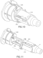
- Figure 9 illustrates the slots 264 of the inner shield 216 being aligned to the locking rails 262 of the needle hub 226 prior to assembly. Subsequently, as illustrated in Figure 10 , the inner shield 216 slides over the needle hub 226 to engage the locking rails 262 in the slots 264. In this position, the locking rails 262 are aligned to openings of the slots 264. Thus, the safety pen needle is in a retracted, unlocked position. The locking rails 262 are exposed because the slots 264 do not enclose the locking rails 262 along a majority of the length of the slot 264.
- Figure 11 illustrates an extended position of the safety pen needle. Specifically, the inner shield 216 moves forward via a spring force from a spring (not illustrated).
- the spring is preferably a torsion spring, although other springs are contemplated.
- Figure 12 illustrates the slots 264 of the inner shield 216 disengaged from the rails 262 of the needle hub 226.
- torsion from the spring causes the inner shield 216 to rotate relative to the needle hub 226.
- the rails 262 are misaligned to the slots 264 and the inner shield 216 can no longer slide back over the needle hub 226. That is, the inner shield 216 is not able to return to the retracted, unlocked position. In this manner, the safety pen needle is in an extended, locked position preventing engagement of the inner shield 216 and the needle hub 226.
- the terms “front,” “rear,” “upper,” “lower,” “upwardly,” “downwardly,” and other orientational descriptors are intended to facilitate the description of the exemplary embodiments of the present invention, and are not intended to limit the structure of the exemplary embodiments of the present invention to any particular position or orientation.
- Terms of degree, such as “substantially” or “approximately” are understood by those of ordinary skill to refer to reasonable ranges outside of the given value, for example, general tolerances associated with manufacturing, assembly, and use of the described embodiments.
Landscapes
- Health & Medical Sciences (AREA)
- Engineering & Computer Science (AREA)
- Heart & Thoracic Surgery (AREA)
- Vascular Medicine (AREA)
- Anesthesiology (AREA)
- Biomedical Technology (AREA)
- Hematology (AREA)
- Life Sciences & Earth Sciences (AREA)
- Animal Behavior & Ethology (AREA)
- General Health & Medical Sciences (AREA)
- Public Health (AREA)
- Veterinary Medicine (AREA)
- Environmental & Geological Engineering (AREA)
- Infusion, Injection, And Reservoir Apparatuses (AREA)
Description
- This application claims the benefit under 35 U.S.C. §119(e) of a
U.S. Provisional Application Serial No. 62/483,629, filed on April 10, 2017 - This invention relates to safety pen needle assemblies.
- Safety pen needle assemblies are well known in the art for use with medical injectors, particularly medication delivery pen injectors. Shielding of a used needle before and after injection is provided by such devices. However, it can be difficult for a health care professional to confirm needle exposure or needle injection as well as provide safety activation. As such, a user may inadvertently inject prematurely or experience a false injection.
- Transmission of biological material or disease is not a concern with the needle being in a clean state; however, a safety activation mechanism can prevent the health care professional or a patient from suffering an incidental needle stick. The safety pen needle must be properly disposed of since the needle cannot be used subsequently on a patient.
- In
US 2002/004648 A1 a disposable double pointed injection needle has a needle hub to which a thin needle cannula is permanently fastened and which needle hub can be mounted on to a syringe comprising a dose setting and injection mechanism and a cartridge containing a liquid medicine to be injected subcutaneously into a human body. The needle hub ofUS 2002/004648 A1 is provided with a safety shield guided on the outside surface of the needle hub. InUS 2002/004648 A1 , the safety shield is urged in a direction away from the needle hub by a spring located between the needle hub and the safety shield. The safety shield ofUS 2002/004648 A1 has a number of protrusions guided in guiding tracks on the outside surface of the needle hub. The guiding tracks inUS 2002/004648 A1 are designed such that the safety shield during injection is moved towards the needle hub, and after injection is moved away from the needle hub by the spring and locked in an irreversible position where the safety shield covers the needle cannula and prevents accidental needle stick injuries. -
WO 03/045480 A1 EP 2 514 450 A1 ,WO 2012/143439 A1 ,WO 2011/117284 A1 , andWO 2009/114777 A1 show further state of the art relevant for the present disclosure. - The present invention is defined in claim 1.
- It is an aspect of the present invention to provide a variable indicator on a safety pen needle to indicate needle cannula exposure and safety activation. Such a safety pen needle provides advantages in informing the health care professional that the needle cannula is extended and injected into a skin of the patient. Also, the safety pen needle provides a safety activation lock to prevent the needle cannula from further exposure or contamination after use.
- The foregoing and/or other aspects of the present invention can be achieved by providing a safety pen needle assembly comprising a hub, a needle cannula engaged to the hub, the needle cannula having a distal end for insertion into a patient, and a proximal end extending into the hub, a sleeve surrounding the hub and needle cannula, a shield including a window, the shield surrounding the sleeve and movable relative to the sleeve from a first position, to a second position and to a third position to expose and cover the distal end of the needle cannula, and a spring urging the shield to move relative to the sleeve from the second position to the third position, wherein the window indicates when the needle cannula is extended in the second position.
- Additional and/or other aspects and advantages of the present invention will be set forth in the description that follows, or will be apparent from the description, or may be learned by practice of the invention.
- The above aspects and features of the present invention will be more apparent from the description for the exemplary embodiments of the present invention taken with reference to the accompanying drawings, in which:
-
Figure 1 illustrates a front view of a first exemplary embodiment of a safety pen needle in a first position; -
Figure 2 illustrates a front view of the safety pen needle ofFigure 1 in a second position; -
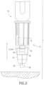
Figure 3 illustrates a front view of the safety pen needle ofFigures 1 and2 in a third position; -
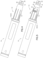
Figure 4 illustrates a perspective view of a second exemplary embodiment of a safety pen needle with a smart ring connected to a medication delivery pen; -
Figure 5 illustrates a perspective view of a third exemplary embodiment of a safety pen needle having a window and a smart ring while connected to a medication delivery pen; -
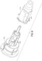
Figure 6 illustrates an exploded perspective view of a fourth exemplary embodiment of a safety pen needle; -
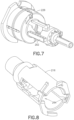
Figure 7 is a right perspective view of a fifth exemplary embodiment of a safety pen needle with a portion of a locking mechanism on a needle hub; -
Figure 8 illustrates a left perspective view of the safety pen needle ofFigure 7 with a portion of the locking mechanism on an inner shield; -
Figure 9 illustrates an exploded perspective view of the safety pen needle ofFigures 7 and 8 ; -
Figure 10 illustrates a left perspective view of the safety pen needle ofFigures 7-9 being assembled; -
Figure 11 illustrates a left perspective view of the safety pen needle ofFigures 7-10 being in an extended position; -
Figure 12 illustrates a left perspective view of the safety pen needle ofFigures 7-11 being aligned in the extended position; and -
Figure 13 illustrates a left perspective view of the safety pen needle ofFigures 7-12 being rotated and locked in the extended position. -
Figure 1 illustrates a typicalmedication delivery pen 10 connected to a first embodiment of asafety pen needle 12. Thesafety pen needle 12 includes ahollow needle cannula 20 engaged to ahub 30. Theneedle cannula 20 includes a sharpened distal end that injects and dispenses medicament to a patient and a proximal end that is in fluid communication with a vial, cartridge or reservoir within themedication delivery pen 10. - The
needle cannula 20 is engaged to thehub 30 and extends beyond a proximal end of thehub 30 at all stages of operation. In one embodiment, thehub 30 includes indicia such as colors, numbers, patterns (such as stripes or spots), textures and/or symbols to indicate needle cannula exposure. Further explanation of the indication of needle cannula exposure is described below. - The
hub 30 is surrounded by amovable sleeve 14. A distal end of thesleeve 14 provides a stopping surface when theneedle cannula 20 contacts a skin of a patient. From the distal end of thesleeve 14, theneedle cannula 20 is extended and injected into a patient. - In a first position, as illustrated in
Figure 1 , when thesafety pen needle 12 is ready for operation, thesleeve 14 encloses and surrounds theneedle cannula 20 andhub 30. Thehub 30 partially encloses theneedle cannula 20 in this first position. In a third position, as illustrated inFigure 3 , when thesafety pen needle 12 is in a safe mode after use, thesleeve 14 partially encloses and surrounds theneedle cannula 20 andhub 30. Thehub 30 fully encloses theneedle cannula 20 in this third position. However, in a second position, as illustrated inFigure 2 , when thesafety pen needle 12 is deployed for medication delivery, theneedle cannula 20 extends beyond thehub 30 and thesleeve 14. - In view of the above, the
safety pen needle 12 is asingle needle cannula 20 device that advantageously hides theneedle cannula 20 when not in use (the first and third positions). In other words, theneedle cannula 20 is only exposed in the second position during medication delivery. Thesafety pen needle 12 having thesingle needle cannula 20 is also different from a typical pen needle magazine where a plurality of pen needles is provided for use by themedication delivery pen 10. - The
sleeve 14 is multicolored and cooperates with ashield 16 to visually indicate the status of thesafety pen needle 12 in the first, second and third positions. In another embodiment, thehub 30 andshield 16 can also cooperate together to display the status of thesafety pen needle 12 in a similar manner. Thesleeve 14 cooperates with awindow 18 in theshield 16 as described below to depict the status of thesafety pen needle 12. Thewindow 18 may comprise an opening (cut-out) in theshield 16 with or without a transparent cover. - The
sleeve 14 is partially surrounded by theshield 16 in the first and third positions. Theshield 16 is movably connected to thehub 30, theneedle cannula 20 and thesleeve 14. Theshield 16 is also pressurized by a spring (seeFigure 6 ) to urge the movement of theshield 16. - Specifically, in the first position as illustrated in
Figure 1 , theshield 16 is in a ready or retracted position and the spring urges theshield 16 toward the retracted position. However, theshield 16 is in an unlocked state and is free to move. The spring does not prevent theshield 16 from moving. Rather, the health care professional can overcome the spring force to move theshield 16. Theshield 16 also partially surrounds thesleeve 14. - In the second position as illustrated in
Figure 2 , the health care professional operates the device by pushing down on themedication delivery pen 10 which is connected to thesafety pen needle 12. This pressure causes theneedle cannula 20 to deploy into the skin of the patient for medication delivery. In this position, theshield 16 is extended and moves to a second position to overcome the pressurized force by the compressed spring. The movement of theshield 16 causes thehub 30 and theneedle cannula 20 to move from a retracted position (first position) to an extended position (second position). Theshield 16 fully surrounds thesleeve 14, and theneedle cannula 20 extends beyond theshield 16 andsleeve 14 in the second position. - In the third position as illustrated in
Figure 3 , the health care professional removes themedication delivery pen 10 that is connected to thesafety pen needle 12 from the patient. Upon removal, the spring urges theshield 16 to move back to the third position. Thesleeve 14 also moves back to expose thehub 30 and theneedle cannula 20. However, theneedle cannula 20 is fully enclosed in thehub 30 in the third position. Thus, the spring advantageously provides automatic retraction of theshield 16 and theneedle cannula 20 after use in the second position as thesafety pen needle 12 moves to the third position. Similar to the first position, theshield 16 partially surrounds thesleeve 14. - In the third position, a locking mechanism (see
Figure 7 ) of thesafety pen needle 12 locks theshield 16 and prevents thesafety pen needle 12 from further use. Specifically, theneedle cannula 20 is fully enclosed by thehub 30 and is unable to be exposed in the second position or return for use in the first position. The locking mechanism may include, for example, a tab on an inner surface of theshield 16 and a slot on an outer surface of thehub 30, although various other configurations are contemplated herein. - According to the first embodiment, the first position and the third position, as illustrated in
Figures 1 and3 , are different from each other. Specifically, in the third position, theshield 16 andsleeve 14 are in a further retracted position when compared to the first position. According to another embodiment, the first position and the third position are the same position. In this alternate embodiment, the locking mechanism is configured to be used in the third position but not the first position. In another embodiment, thesleeve 14 is rotated to angularly displace the third position from the first and second position. - The
shield 16 includes thewindow 18 which visibly indicates needle cannula exposure and safety activation. Specifically, as illustrated inFigure 1 , thewindow 18 visually exposes awhite portion 36 of thesleeve 14 to represent the ready position. In this first position, thesafety pen needle 12 is ready for operation and is in an unlocked state to allow various components to move. - As illustrated in
Figure 2 , thewindow 18 visually exposes agreen portion 32 of thesleeve 14 to represent the fully deployed position. In this second position, theneedle cannula 20 of thesafety pen needle 12 is exposed, inserted into the patient and is dispensing medication. This visual indication advantageously provides the health care professional confirmation that the needle cannula is in the skin of the patient. This visual indication is a significant improvement over a mere tactile notification or needle cannula sensation that the health care professional may previously have relied upon to confirm needle cannula insertion. Another advantage this visual indication provides is less training for health care professionals and reduced risk of injection errors. - As illustrated in
Figure 3 , thewindow 18 visually exposes a red portion 34 of thesleeve 14 to represent the safe mode in the third position. In this third position, theneedle cannula 20 is retracted into thehub 30 and is locked from further exposure and use. This visual indication advantageously provides the health care professional notice that thesafety pen needle 12 is in safe activation mode. Such an indication protects patients and health care professionals from being contaminated by used needle cannulas. - In other embodiments, alternative types of indicia such as numbers, patterns (such as stripes or spots), textures and/or symbols can replace or supplement the green, red or
white portions sleeve 14 as described above. Different patterns or textures can advantageously aid those who are blind, color blind or in cases where red/green colors, for example, are perceived differently in other countries. Additionally, in one embodiment, thewindow 18 can be tinted to adjust what is visually displayed. -
Figure 4 illustrates a second embodiment of thesafety pen needle 12 described above having a smart ring 50 but without a window. The smart ring 50 is a circular ring disposed at a proximal end of thesafety pen needle 12. When thesafety pen needle 12 is engaged to themedication delivery pen 10, the smart ring 50 is disposed between thesafety pen needle 12 and themedication delivery pen 10. - The smart ring 50 includes electronics such as electrical contacts or sensors 52 that cooperate with the remaining components of the
safety pen needle 12 to sense positional and/or spatial arrangements to determine a position of theshield 16 and dose data. For example, the smart ring 50 is able to determine needle insertion and needle exposure time, needle insertion rate and needle exposure rate, the number of injections performed, time intervals between injections and the number of needles used or available for injection. - The smart ring 50 also determines the position of the
shield 16 to identify which of the three positions thesafety pen needle 12 is operating in as described above. The smart ring 50 communicates positional data or dose data to an external smart device for monitoring and status notification such as if thesafety pen needle 12 is in the first, second or third positions. The external smart device can be, for example, a mobile phone, laptop, iPad, a smart medication delivery pen or other processing device. - The smart ring 50 communicates data wirelessly or via a wireline connection to the external smart device. Different wireless connectivity methods can be used (e.g., Bluetooth™ or Wi-Fi or near field communication (NFC) technology) which can, in turn, impact device pairing if needed and the need for proximity of the external smart device. For example, Bluetooth™ employs a particular device pairing process. The proximity of the two communicating platforms relative to each other depends on the connectivity method used.
-
Figure 5 illustrates a third embodiment of thesafety pen needle 12 described above having a smart ring 50 and thewindow 18. This embodiment incorporates the smart ring 50 technology described in the second embodiment, as well as the visual indication feature of thewindow 18 described in the first embodiment. This configuration advantageously provides data communication and status indication through thewindow 18 at the same time. - In this embodiment, the
sleeve 14 is rotated during operation to angularly displace the second position from the first and third position. Accordingly, thesleeve 14 rotates and axially moves from the first position (white portion 36) to the second position (green portion 32) and displays the status through thewindow 18. After use, thesleeve 14 rotates and axially moves from the second position (green portion 32) to the third position (red portion 34). - In addition to the advantages described above in the first embodiment, the use of the smart ring 50 in the
safety pen needle 12 of the second and third embodiments can prohibit injection until the needle cannula has been fully exposed or fully extended. Such a feature can further mitigate the risk of a failed injection. -
Figure 6 illustrates a fourth embodiment of thesafety pen needle 110 that functions in a similar manner as the embodiments described above. Specifically, thesafety pen needle 110 includes anouter shield 148 with threecolored dots sleeve 146 having awindow 118. Thesafety pen needle 110 further includes aninner shield 116 and aneedle 114 fixed to aneedle hub 126 that cooperates with a spring 144 to allow forneedle 114 movement between an extended and a retracted position. - The
outer shield 148 slides in and out and rotates, depending on the state of thesafety pen needle 110. Three dots, white 136, red 134, and green 132 are located on theouter shield 148 such that one of the threedots window 118 in thesleeve 146, depending on the state of thesafety pen needle 110. - In the ready position (as delivered), the
white dot 136 is visible in thewindow 118. During injection, theouter shield 148 will retract into thesleeve 146 and rotate, bringing thegreen dot 132 into view in thewindow 118. In the locked state, theshield 148 will move forward, bringing the red dot 134 into view through thewindow 118. The spring 144 provides a spring force to return theouter shield 148 of thesafety pen needle 110 into the retracted position. - In other embodiments, alternative types of indicia such as numbers, patterns (such as stripes or spots), textures and/or symbols can replace or supplement the green, red or white
colored dots outer shield 148 as described above. Different patterns or textures can advantageously aid those who are blind, color blind or in cases where red/green colors, for example, are perceived differently in other countries. -
Figures 7-13 illustrate a fifth embodiment of the safety pen needle having a locking mechanism comprising lockingrails 262 andslots 264 as described below.Figure 7 illustrates aneedle hub 226 having the locking rails 262. The locking rails 262 are an extruded rectangular member along a longitudinal surface of theneedle hub 226. The locking rails 262 are disposed on an outer surface of theneedle hub 226 in a substantially central axial position. Two lockingrails 262 are disclosed to be equidistant along the outer surface of theneedle hub 226, although more or fewer locking rails are contemplated. -
Figure 8 illustrates aninner shield 216 having theslots 264. Theslots 264 are internal rectangular cavities disposed at a proximal end surface of theinner shield 216. As theslots 264 extend beyond the proximal end surface at the proximal end of theinner shield 216, theslots 264 are open and exposed along a length of theinner shield 216. Theslots 264 are sized to engage the locking rails 262 of theneedle hub 226. More orfewer slots 264 are contemplated based on the number of corresponding locking rails 262 in theneedle hub 226. -
Figure 9 illustrates theslots 264 of theinner shield 216 being aligned to the locking rails 262 of theneedle hub 226 prior to assembly. Subsequently, as illustrated inFigure 10 , theinner shield 216 slides over theneedle hub 226 to engage the locking rails 262 in theslots 264. In this position, the locking rails 262 are aligned to openings of theslots 264. Thus, the safety pen needle is in a retracted, unlocked position. The locking rails 262 are exposed because theslots 264 do not enclose the locking rails 262 along a majority of the length of theslot 264. -
Figure 11 illustrates an extended position of the safety pen needle. Specifically, theinner shield 216 moves forward via a spring force from a spring (not illustrated). The spring is preferably a torsion spring, although other springs are contemplated.Figure 12 illustrates theslots 264 of theinner shield 216 disengaged from therails 262 of theneedle hub 226. - At this point, as illustrated in
Figure 13 , torsion from the spring causes theinner shield 216 to rotate relative to theneedle hub 226. Thus, therails 262 are misaligned to theslots 264 and theinner shield 216 can no longer slide back over theneedle hub 226. That is, theinner shield 216 is not able to return to the retracted, unlocked position. In this manner, the safety pen needle is in an extended, locked position preventing engagement of theinner shield 216 and theneedle hub 226. - The foregoing detailed description of the certain exemplary embodiments has been provided for the purpose of explaining the principles of the invention and its practical application, thereby enabling others skilled in the art to understand the invention for various embodiments and with various modifications as are suited to the particular use contemplated. This description is not necessarily intended to be exhaustive or to limit the invention to the precise embodiments disclosed. Any of the embodiments and/or elements disclosed herein may be combined with one another to form various additional embodiments not specifically disclosed, as long as they do not contradict each other. Accordingly, additional embodiments are possible and are intended to be encompassed within this specification and the scope of the invention. The specification describes specific examples to accomplish a more general goal that may be accomplished in another way.
- As used in this application, the terms "front," "rear," "upper," "lower," "upwardly," "downwardly," and other orientational descriptors are intended to facilitate the description of the exemplary embodiments of the present invention, and are not intended to limit the structure of the exemplary embodiments of the present invention to any particular position or orientation. Terms of degree, such as "substantially" or "approximately" are understood by those of ordinary skill to refer to reasonable ranges outside of the given value, for example, general tolerances associated with manufacturing, assembly, and use of the described embodiments.
Claims (16)
- A safety pen needle assembly (12, 110) comprising:a hub (30, 126);a needle cannula (20, 114) cooperating with the hub, the needle cannula having a distal end for insertion into a patient, and a proximal end extending into the hub;a sleeve (14, 146) surrounding the hub and needle cannula;a shield (16) including a window (18, 118), the shield surrounding the sleeve and movable relative to the sleeve from a first position where the sleeve encloses the needle cannula and hub, to a second position where the needle cannula extends beyond the hub and the sleeve;a locking mechanism (260) that engages the shield to the hub to prevent further use of the needle cannula; anda spring (144) urging the shield;characterized in that the safety pen needle assembly (12, 110) further comprises:the shield (16) being-movable relative to the sleeve to a third position where the distal end of the needle cannula is partially surrounded by the sleeve and the hub encloses the needle cannula;the spring (144) urging the shield to move relative to the sleeve from the second position where the spring is compressed to the third position; anda smart ring (50) having electrical contacts or sensors that determine two or more of a position of the shield, needle insertion and needle exposure time, needle insertion rate and needle exposure rate, the number of injections performed, time intervals between injections or the number of needles used or available for injection; whereinthe window indicates needle cannula exposure via an indicia on the hub and safety activation via the locking mechanism.
- The safety pen needle assembly of claim 1, wherein the sleeve or hub is white through the window in the first position.
- The safety pen needle assembly of claim 1, wherein the sleeve or hub is green through the window in the second position.
- The safety pen needle assembly of claim 1, wherein the sleeve or hub is red through the window in the third position.
- The safety pen needle assembly of claim 1, wherein the sleeve or hub displays numbers, patterns, textures and/or symbols through the window to indicate the first, second and third positions.
- The safety pen needle assembly of claim 1, wherein the first position is an unlocked position where the shield is free to move to expose or cover the needle cannula.
- The safety pen needle assembly of claim 1, wherein the third position is a locked position where the shield is locked in place to fixedly cover the needle cannula.
- The safety pen needle assembly of claim 1, wherein the needle cannula is retracted and covered by the hub in the first and third positions.
- The safety pen needle assembly of claim 1, wherein the smart ring communicates with a smart device.
- The safety pen needle assembly of claim 9, wherein the smart ring communicates a ready, fully deployed or safe mode.
- The safety pen needle assembly of claim 1, wherein the smart ring is disposed at a proximal end of the safety pen needle assembly.
- A medication delivery safety pen needle assembly (12, 110) comprising:a medication delivery pen (10); andthe safety pen needle assembly of claim 1, whereinthe smart ring is disposed at a distal end of the medication delivery pen and at a proximal end of the safety pen needle assembly.
- The safety pen needle assembly of claim 1, wherein the shield includes slots (264) that engage rails (262) on the hub in a retracted, unlocked position.
- The safety pen needle assembly of claim 13, wherein the slots are not aligned to the rails in an extended, locked position.
- The safety pen needle assembly of claim 13, further comprising a spring that rotates the shield with respect to the hub to misalign the slots to the rails.
- The safety pen needle assembly of claim 1, wherein the window visually exposes a first portion (36) of the sleeve to represent a ready position or the first position, the window visually exposes a second portion (32) of the sleeve to represent a fully deployed position or the second position, and the window visually exposes a third portion (34) of the sleeve to represent a safe mode in the third position where the needle cannula is locked from further exposure and use.
Applications Claiming Priority (2)
| Application Number | Priority Date | Filing Date | Title |
|---|---|---|---|
| US201762483629P | 2017-04-10 | 2017-04-10 | |
| PCT/US2018/026078 WO2018191076A1 (en) | 2017-04-10 | 2018-04-04 | Safety pen needle variable indicator |
Publications (3)
| Publication Number | Publication Date |
|---|---|
| EP3609558A1 EP3609558A1 (en) | 2020-02-19 |
| EP3609558A4 EP3609558A4 (en) | 2020-12-16 |
| EP3609558B1 true EP3609558B1 (en) | 2025-06-11 |
Family
ID=63793731
Family Applications (1)
| Application Number | Title | Priority Date | Filing Date |
|---|---|---|---|
| EP18784982.3A Active EP3609558B1 (en) | 2017-04-10 | 2018-04-04 | Safety pen needle variable indicator |
Country Status (6)
| Country | Link |
|---|---|
| US (1) | US11364350B2 (en) |
| EP (1) | EP3609558B1 (en) |
| JP (1) | JP7370315B2 (en) |
| CN (2) | CN114949457A (en) |
| CA (1) | CA3055788A1 (en) |
| WO (1) | WO2018191076A1 (en) |
Families Citing this family (4)
| Publication number | Priority date | Publication date | Assignee | Title |
|---|---|---|---|---|
| JP7378436B2 (en) * | 2018-06-25 | 2023-11-13 | サノフイ | drug delivery device |
| WO2022098592A1 (en) * | 2020-11-04 | 2022-05-12 | Amgen Inc. | Drug delivery device assembly and accessory for drug delivery device |
| JP7525955B2 (en) | 2021-04-08 | 2024-07-31 | ラブ ライフサイエンシズ エルエルシー | Prefilled Syringe Safety Devices and Syringes |
| WO2025114264A1 (en) | 2023-11-28 | 2025-06-05 | Novo Nordisk A/S | Shielded needle unit with lock indicator |
Family Cites Families (24)
| Publication number | Priority date | Publication date | Assignee | Title |
|---|---|---|---|---|
| US6547764B2 (en) * | 2000-05-31 | 2003-04-15 | Novo Nordisk A/S | Double pointed injection needle |
| EP1289587B1 (en) | 2000-05-31 | 2005-08-03 | Novo Nordisk A/S | A disposable double pointed injection needle |
| WO2002009797A1 (en) | 2000-08-02 | 2002-02-07 | Becton Dickinson And Company | Pen needle and safety shield system |
| ES2257597T3 (en) * | 2001-11-30 | 2006-08-01 | Novo Nordisk A/S | SAFETY NEEDLE ASSEMBLY. |
| US20090280065A1 (en) * | 2006-04-10 | 2009-11-12 | Willian Mary K | Uses and Compositions for Treatment of Psoriasis |
| US6805686B1 (en) | 2003-05-06 | 2004-10-19 | Abbott Laboratories | Autoinjector with extendable needle protector shroud |
| US7497847B2 (en) * | 2003-11-03 | 2009-03-03 | Becton, Dickinson And Company | Safety shield system for a syringe |
| CA2719110C (en) | 2008-03-13 | 2017-07-25 | Becton, Dickinson And Company | Safety needle assembly |
| GB2463034B (en) * | 2008-08-28 | 2012-11-07 | Owen Mumford Ltd | Autoinjection devices |
| US8876781B2 (en) * | 2009-06-18 | 2014-11-04 | Shl Group Ab | Safety pen needle device |
| CN102905747B (en) * | 2010-03-25 | 2014-10-29 | 赛诺菲-安万特德国有限公司 | Needle assembly |
| AU2011231688B2 (en) * | 2010-03-25 | 2014-12-04 | Sanofi-Aventis Deutschland Gmbh | Medicated module with user selection |
| CA2818833A1 (en) * | 2010-11-29 | 2012-06-07 | Thomas Urs Thueer | Medicated module with automatic reservoir engagement |
| EP2514450A1 (en) | 2011-04-21 | 2012-10-24 | Sanofi-Aventis Deutschland GmbH | Medicated module with automatic reservoir engagement and magnetic lock mechanism |
| CA2832957A1 (en) * | 2011-04-21 | 2012-10-26 | Sanofi-Aventis Deutschland Gmbh | Medicated module with automatic reservoir engagement and lock mechanism |
| EP2699292A1 (en) | 2011-04-21 | 2014-02-26 | Sanofi-Aventis Deutschland GmbH | Medicated module with automatic activation mechanism |
| US8496619B2 (en) * | 2011-07-15 | 2013-07-30 | Antares Pharma, Inc. | Injection device with cammed ram assembly |
| EP2578257A1 (en) * | 2011-10-06 | 2013-04-10 | Sanofi-Aventis Deutschland GmbH | Needle safety device |
| EP2789357B1 (en) * | 2011-12-09 | 2017-04-26 | Panasonic Healthcare Holdings Co., Ltd. | Pharmaceutical syringe unit and pharmaceutical injection device |
| EP2716318A1 (en) * | 2012-10-04 | 2014-04-09 | Sanofi-Aventis Deutschland GmbH | Medicament delivery device with medicament delivery initiation indicator |
| ES2806983T3 (en) | 2015-04-10 | 2021-02-19 | Novo Nordisk As | Injection medical device that has a shield |
| GB201507981D0 (en) * | 2015-05-11 | 2015-06-24 | Owen Mumford Ltd | Needle assemblies |
| JP2018515232A (en) | 2015-05-12 | 2018-06-14 | ノボ・ノルデイスク・エー/エス | Rotation sensor structure for drug delivery device |
| EP3380159B1 (en) * | 2015-11-27 | 2019-10-23 | Sanofi-Aventis Deutschland GmbH | An injection device |
-
2018
- 2018-04-04 WO PCT/US2018/026078 patent/WO2018191076A1/en not_active Ceased
- 2018-04-04 CN CN202210733149.5A patent/CN114949457A/en active Pending
- 2018-04-04 JP JP2020504097A patent/JP7370315B2/en active Active
- 2018-04-04 CN CN201880024153.6A patent/CN110494179B/en active Active
- 2018-04-04 US US16/603,990 patent/US11364350B2/en active Active
- 2018-04-04 EP EP18784982.3A patent/EP3609558B1/en active Active
- 2018-04-04 CA CA3055788A patent/CA3055788A1/en active Pending
Also Published As
| Publication number | Publication date |
|---|---|
| WO2018191076A1 (en) | 2018-10-18 |
| US11364350B2 (en) | 2022-06-21 |
| US20200114090A1 (en) | 2020-04-16 |
| EP3609558A1 (en) | 2020-02-19 |
| JP7370315B2 (en) | 2023-10-27 |
| CN114949457A (en) | 2022-08-30 |
| EP3609558A4 (en) | 2020-12-16 |
| CN110494179B (en) | 2022-07-22 |
| CN110494179A (en) | 2019-11-22 |
| JP2020516420A (en) | 2020-06-11 |
| CA3055788A1 (en) | 2018-10-18 |
Similar Documents
| Publication | Publication Date | Title |
|---|---|---|
| CN102905747B (en) | Needle assembly | |
| EP1605992B1 (en) | Holder with safety shield for a drug delivery device | |
| EP2231235B1 (en) | Pen needle assembly with needle insertion mechanism | |
| CN105592876B (en) | Safety Needle Equipment | |
| US11364350B2 (en) | Safety pen needle variable indicator | |
| ES2247343T3 (en) | SECURITY PROTECTION SYSTEM FOR PRE-LOADED SYRINGES. | |
| JP2005530597A (en) | Medical needle assembly | |
| CN110958895A (en) | A safety injection device, syringe and assembly method thereof | |
| CN104321099A (en) | Infusion device with safety feature for preventing inadvertent activation | |
| KR20140027466A (en) | Injection device | |
| EP3047866B1 (en) | Autoinjector having an end-of-dose visual indicator | |
| MX2012004446A (en) | Palm activated drug delivery device. | |
| MX2012015039A (en) | Safety device for a pre-filled syringe and injection device. | |
| US20100160869A1 (en) | Medical Needle Assemblies | |
| EP3534987B1 (en) | Adjustable dose drug delivery system | |
| CA2671759A1 (en) | Shieldable needle assembly with biased safety shield | |
| EP3749398B1 (en) | Safety needle device | |
| WO2021211412A1 (en) | Injection device with passive safety mechanism | |
| CN214129793U (en) | Needle shield for a drug delivery device | |
| EP4129367B1 (en) | Cap assembly for a needle | |
| WO2025160425A1 (en) | Pre-filled syringe safety devices and injectors, systems, and methods of use | |
| WO2008132518A1 (en) | Piercing needle assembly irreversibly locked with a reversible latching mechanism | |
| HK1234356A1 (en) | Medicine delivery device with restricted access filling port |
Legal Events
| Date | Code | Title | Description |
|---|---|---|---|
| STAA | Information on the status of an ep patent application or granted ep patent |
Free format text: STATUS: THE INTERNATIONAL PUBLICATION HAS BEEN MADE |
|
| PUAI | Public reference made under article 153(3) epc to a published international application that has entered the european phase |
Free format text: ORIGINAL CODE: 0009012 |
|
| STAA | Information on the status of an ep patent application or granted ep patent |
Free format text: STATUS: REQUEST FOR EXAMINATION WAS MADE |
|
| 17P | Request for examination filed |
Effective date: 20191002 |
|
| AK | Designated contracting states |
Kind code of ref document: A1 Designated state(s): AL AT BE BG CH CY CZ DE DK EE ES FI FR GB GR HR HU IE IS IT LI LT LU LV MC MK MT NL NO PL PT RO RS SE SI SK SM TR |
|
| AX | Request for extension of the european patent |
Extension state: BA ME |
|
| RIN1 | Information on inventor provided before grant (corrected) |
Inventor name: MANOCCHIO, JOHN Inventor name: OZA, KUNJAL Inventor name: VIEIRA, LOUIS Inventor name: BOWEN, MARK |
|
| DAV | Request for validation of the european patent (deleted) | ||
| DAX | Request for extension of the european patent (deleted) | ||
| A4 | Supplementary search report drawn up and despatched |
Effective date: 20201113 |
|
| RIC1 | Information provided on ipc code assigned before grant |
Ipc: A61M 5/20 20060101AFI20201109BHEP Ipc: A61M 5/32 20060101ALI20201109BHEP Ipc: A61M 5/24 20060101ALI20201109BHEP |
|
| STAA | Information on the status of an ep patent application or granted ep patent |
Free format text: STATUS: EXAMINATION IS IN PROGRESS |
|
| 17Q | First examination report despatched |
Effective date: 20210730 |
|
| RAP1 | Party data changed (applicant data changed or rights of an application transferred) |
Owner name: EMBECTA CORP. |
|
| GRAP | Despatch of communication of intention to grant a patent |
Free format text: ORIGINAL CODE: EPIDOSNIGR1 |
|
| STAA | Information on the status of an ep patent application or granted ep patent |
Free format text: STATUS: GRANT OF PATENT IS INTENDED |
|
| INTG | Intention to grant announced |
Effective date: 20250102 |
|
| GRAS | Grant fee paid |
Free format text: ORIGINAL CODE: EPIDOSNIGR3 |
|
| GRAA | (expected) grant |
Free format text: ORIGINAL CODE: 0009210 |
|
| STAA | Information on the status of an ep patent application or granted ep patent |
Free format text: STATUS: THE PATENT HAS BEEN GRANTED |
|
| AK | Designated contracting states |
Kind code of ref document: B1 Designated state(s): AL AT BE BG CH CY CZ DE DK EE ES FI FR GB GR HR HU IE IS IT LI LT LU LV MC MK MT NL NO PL PT RO RS SE SI SK SM TR |
|
| REG | Reference to a national code |
Ref country code: GB Ref legal event code: FG4D |
|
| REG | Reference to a national code |
Ref country code: CH Ref legal event code: EP |
|
| REG | Reference to a national code |
Ref country code: IE Ref legal event code: FG4D |
|
| REG | Reference to a national code |
Ref country code: DE Ref legal event code: R096 Ref document number: 602018082548 Country of ref document: DE |
|
| PG25 | Lapsed in a contracting state [announced via postgrant information from national office to epo] |
Ref country code: FI Free format text: LAPSE BECAUSE OF FAILURE TO SUBMIT A TRANSLATION OF THE DESCRIPTION OR TO PAY THE FEE WITHIN THE PRESCRIBED TIME-LIMIT Effective date: 20250611 Ref country code: ES Free format text: LAPSE BECAUSE OF FAILURE TO SUBMIT A TRANSLATION OF THE DESCRIPTION OR TO PAY THE FEE WITHIN THE PRESCRIBED TIME-LIMIT Effective date: 20250611 |
|
| REG | Reference to a national code |
Ref country code: LT Ref legal event code: MG9D |
|
| PG25 | Lapsed in a contracting state [announced via postgrant information from national office to epo] |
Ref country code: NO Free format text: LAPSE BECAUSE OF FAILURE TO SUBMIT A TRANSLATION OF THE DESCRIPTION OR TO PAY THE FEE WITHIN THE PRESCRIBED TIME-LIMIT Effective date: 20250911 Ref country code: GR Free format text: LAPSE BECAUSE OF FAILURE TO SUBMIT A TRANSLATION OF THE DESCRIPTION OR TO PAY THE FEE WITHIN THE PRESCRIBED TIME-LIMIT Effective date: 20250912 |
|
| REG | Reference to a national code |
Ref country code: NL Ref legal event code: MP Effective date: 20250611 |
|
| PG25 | Lapsed in a contracting state [announced via postgrant information from national office to epo] |
Ref country code: BG Free format text: LAPSE BECAUSE OF FAILURE TO SUBMIT A TRANSLATION OF THE DESCRIPTION OR TO PAY THE FEE WITHIN THE PRESCRIBED TIME-LIMIT Effective date: 20250611 |
|
| PG25 | Lapsed in a contracting state [announced via postgrant information from national office to epo] |
Ref country code: HR Free format text: LAPSE BECAUSE OF FAILURE TO SUBMIT A TRANSLATION OF THE DESCRIPTION OR TO PAY THE FEE WITHIN THE PRESCRIBED TIME-LIMIT Effective date: 20250611 |
|
| PG25 | Lapsed in a contracting state [announced via postgrant information from national office to epo] |
Ref country code: RS Free format text: LAPSE BECAUSE OF FAILURE TO SUBMIT A TRANSLATION OF THE DESCRIPTION OR TO PAY THE FEE WITHIN THE PRESCRIBED TIME-LIMIT Effective date: 20250911 |
|
| PG25 | Lapsed in a contracting state [announced via postgrant information from national office to epo] |
Ref country code: LV Free format text: LAPSE BECAUSE OF FAILURE TO SUBMIT A TRANSLATION OF THE DESCRIPTION OR TO PAY THE FEE WITHIN THE PRESCRIBED TIME-LIMIT Effective date: 20250611 |
|
| PG25 | Lapsed in a contracting state [announced via postgrant information from national office to epo] |
Ref country code: NL Free format text: LAPSE BECAUSE OF FAILURE TO SUBMIT A TRANSLATION OF THE DESCRIPTION OR TO PAY THE FEE WITHIN THE PRESCRIBED TIME-LIMIT Effective date: 20250611 |
|
| PG25 | Lapsed in a contracting state [announced via postgrant information from national office to epo] |
Ref country code: PT Free format text: LAPSE BECAUSE OF FAILURE TO SUBMIT A TRANSLATION OF THE DESCRIPTION OR TO PAY THE FEE WITHIN THE PRESCRIBED TIME-LIMIT Effective date: 20251013 |
|
| REG | Reference to a national code |
Ref country code: AT Ref legal event code: MK05 Ref document number: 1801872 Country of ref document: AT Kind code of ref document: T Effective date: 20250611 |
|
| PG25 | Lapsed in a contracting state [announced via postgrant information from national office to epo] |
Ref country code: IS Free format text: LAPSE BECAUSE OF FAILURE TO SUBMIT A TRANSLATION OF THE DESCRIPTION OR TO PAY THE FEE WITHIN THE PRESCRIBED TIME-LIMIT Effective date: 20251011 |
|
| PG25 | Lapsed in a contracting state [announced via postgrant information from national office to epo] |
Ref country code: AT Free format text: LAPSE BECAUSE OF FAILURE TO SUBMIT A TRANSLATION OF THE DESCRIPTION OR TO PAY THE FEE WITHIN THE PRESCRIBED TIME-LIMIT Effective date: 20250611 Ref country code: SM Free format text: LAPSE BECAUSE OF FAILURE TO SUBMIT A TRANSLATION OF THE DESCRIPTION OR TO PAY THE FEE WITHIN THE PRESCRIBED TIME-LIMIT Effective date: 20250611 |
|
| PG25 | Lapsed in a contracting state [announced via postgrant information from national office to epo] |
Ref country code: CZ Free format text: LAPSE BECAUSE OF FAILURE TO SUBMIT A TRANSLATION OF THE DESCRIPTION OR TO PAY THE FEE WITHIN THE PRESCRIBED TIME-LIMIT Effective date: 20250611 |
|
| PG25 | Lapsed in a contracting state [announced via postgrant information from national office to epo] |
Ref country code: PL Free format text: LAPSE BECAUSE OF FAILURE TO SUBMIT A TRANSLATION OF THE DESCRIPTION OR TO PAY THE FEE WITHIN THE PRESCRIBED TIME-LIMIT Effective date: 20250611 |
|
| PG25 | Lapsed in a contracting state [announced via postgrant information from national office to epo] |
Ref country code: EE Free format text: LAPSE BECAUSE OF FAILURE TO SUBMIT A TRANSLATION OF THE DESCRIPTION OR TO PAY THE FEE WITHIN THE PRESCRIBED TIME-LIMIT Effective date: 20250611 |
|
| PG25 | Lapsed in a contracting state [announced via postgrant information from national office to epo] |
Ref country code: RO Free format text: LAPSE BECAUSE OF FAILURE TO SUBMIT A TRANSLATION OF THE DESCRIPTION OR TO PAY THE FEE WITHIN THE PRESCRIBED TIME-LIMIT Effective date: 20250611 Ref country code: SK Free format text: LAPSE BECAUSE OF FAILURE TO SUBMIT A TRANSLATION OF THE DESCRIPTION OR TO PAY THE FEE WITHIN THE PRESCRIBED TIME-LIMIT Effective date: 20250611 |
|
| REG | Reference to a national code |
Ref country code: DE Ref legal event code: R097 Ref document number: 602018082548 Country of ref document: DE |
|
| PG25 | Lapsed in a contracting state [announced via postgrant information from national office to epo] |
Ref country code: DK Free format text: LAPSE BECAUSE OF FAILURE TO SUBMIT A TRANSLATION OF THE DESCRIPTION OR TO PAY THE FEE WITHIN THE PRESCRIBED TIME-LIMIT Effective date: 20250611 |
|
| PG25 | Lapsed in a contracting state [announced via postgrant information from national office to epo] |
Ref country code: IT Free format text: LAPSE BECAUSE OF FAILURE TO SUBMIT A TRANSLATION OF THE DESCRIPTION OR TO PAY THE FEE WITHIN THE PRESCRIBED TIME-LIMIT Effective date: 20250611 |
|
| PLBE | No opposition filed within time limit |
Free format text: ORIGINAL CODE: 0009261 |
|
| STAA | Information on the status of an ep patent application or granted ep patent |
Free format text: STATUS: NO OPPOSITION FILED WITHIN TIME LIMIT |
|
| REG | Reference to a national code |
Ref country code: CH Ref legal event code: L10 Free format text: ST27 STATUS EVENT CODE: U-0-0-L10-L00 (AS PROVIDED BY THE NATIONAL OFFICE) Effective date: 20260423 |