EP3609400B1 - System zur elektrophysiologischen kartierung - Google Patents
System zur elektrophysiologischen kartierung Download PDFInfo
- Publication number
- EP3609400B1 EP3609400B1 EP18752662.9A EP18752662A EP3609400B1 EP 3609400 B1 EP3609400 B1 EP 3609400B1 EP 18752662 A EP18752662 A EP 18752662A EP 3609400 B1 EP3609400 B1 EP 3609400B1
- Authority
- EP
- European Patent Office
- Prior art keywords
- information regarding
- signal
- signal quality
- electrophysiological
- acquisition time
- Prior art date
- Legal status (The legal status is an assumption and is not a legal conclusion. Google has not performed a legal analysis and makes no representation as to the accuracy of the status listed.)
- Active
Links
Images


Classifications
-
- A—HUMAN NECESSITIES
- A61—MEDICAL OR VETERINARY SCIENCE; HYGIENE
- A61B—DIAGNOSIS; SURGERY; IDENTIFICATION
- A61B5/00—Measuring for diagnostic purposes; Identification of persons
- A61B5/72—Signal processing specially adapted for physiological signals or for diagnostic purposes
- A61B5/7221—Determining signal validity, reliability or quality
-
- A—HUMAN NECESSITIES
- A61—MEDICAL OR VETERINARY SCIENCE; HYGIENE
- A61B—DIAGNOSIS; SURGERY; IDENTIFICATION
- A61B5/00—Measuring for diagnostic purposes; Identification of persons
- A61B5/06—Devices, other than using radiation, for detecting or locating foreign bodies ; Determining position of diagnostic devices within or on the body of the patient
- A61B5/061—Determining position of a probe within the body employing means separate from the probe, e.g. sensing internal probe position employing impedance electrodes on the surface of the body
- A61B5/063—Determining position of a probe within the body employing means separate from the probe, e.g. sensing internal probe position employing impedance electrodes on the surface of the body using impedance measurements
-
- A—HUMAN NECESSITIES
- A61—MEDICAL OR VETERINARY SCIENCE; HYGIENE
- A61B—DIAGNOSIS; SURGERY; IDENTIFICATION
- A61B5/00—Measuring for diagnostic purposes; Identification of persons
- A61B5/24—Detecting, measuring or recording bioelectric or biomagnetic signals of the body or parts thereof
- A61B5/25—Bioelectric electrodes therefor
- A61B5/279—Bioelectric electrodes therefor specially adapted for particular uses
- A61B5/28—Bioelectric electrodes therefor specially adapted for particular uses for electrocardiography [ECG]
- A61B5/283—Invasive
- A61B5/287—Holders for multiple electrodes, e.g. electrode catheters for electrophysiological study [EPS]
-
- A—HUMAN NECESSITIES
- A61—MEDICAL OR VETERINARY SCIENCE; HYGIENE
- A61B—DIAGNOSIS; SURGERY; IDENTIFICATION
- A61B5/00—Measuring for diagnostic purposes; Identification of persons
- A61B5/24—Detecting, measuring or recording bioelectric or biomagnetic signals of the body or parts thereof
- A61B5/316—Modalities, i.e. specific diagnostic methods
- A61B5/318—Heart-related electrical modalities, e.g. electrocardiography [ECG]
- A61B5/339—Displays specially adapted therefor
-
- A—HUMAN NECESSITIES
- A61—MEDICAL OR VETERINARY SCIENCE; HYGIENE
- A61B—DIAGNOSIS; SURGERY; IDENTIFICATION
- A61B5/00—Measuring for diagnostic purposes; Identification of persons
- A61B5/68—Arrangements of detecting, measuring or recording means, e.g. sensors, in relation to patient
- A61B5/6846—Arrangements of detecting, measuring or recording means, e.g. sensors, in relation to patient specially adapted to be brought in contact with an internal body part, i.e. invasive
- A61B5/6885—Monitoring or controlling sensor contact pressure
-
- A—HUMAN NECESSITIES
- A61—MEDICAL OR VETERINARY SCIENCE; HYGIENE
- A61B—DIAGNOSIS; SURGERY; IDENTIFICATION
- A61B5/00—Measuring for diagnostic purposes; Identification of persons
- A61B5/68—Arrangements of detecting, measuring or recording means, e.g. sensors, in relation to patient
- A61B5/6846—Arrangements of detecting, measuring or recording means, e.g. sensors, in relation to patient specially adapted to be brought in contact with an internal body part, i.e. invasive
- A61B5/6886—Monitoring or controlling distance between sensor and tissue
-
- A—HUMAN NECESSITIES
- A61—MEDICAL OR VETERINARY SCIENCE; HYGIENE
- A61B—DIAGNOSIS; SURGERY; IDENTIFICATION
- A61B5/00—Measuring for diagnostic purposes; Identification of persons
- A61B5/72—Signal processing specially adapted for physiological signals or for diagnostic purposes
- A61B5/7235—Details of waveform analysis
- A61B5/7264—Classification of physiological signals or data, e.g. using neural networks, statistical classifiers, expert systems or fuzzy systems
-
- A—HUMAN NECESSITIES
- A61—MEDICAL OR VETERINARY SCIENCE; HYGIENE
- A61B—DIAGNOSIS; SURGERY; IDENTIFICATION
- A61B5/00—Measuring for diagnostic purposes; Identification of persons
- A61B5/74—Details of notification to user or communication with user or patient; User input means
- A61B5/742—Details of notification to user or communication with user or patient; User input means using visual displays
- A61B5/743—Displaying an image simultaneously with additional graphical information, e.g. symbols, charts, function plots
-
- G—PHYSICS
- G16—INFORMATION AND COMMUNICATION TECHNOLOGY [ICT] SPECIALLY ADAPTED FOR SPECIFIC APPLICATION FIELDS
- G16H—HEALTHCARE INFORMATICS, i.e. INFORMATION AND COMMUNICATION TECHNOLOGY [ICT] SPECIALLY ADAPTED FOR THE HANDLING OR PROCESSING OF MEDICAL OR HEALTHCARE DATA
- G16H50/00—ICT specially adapted for medical diagnosis, medical simulation or medical data mining; ICT specially adapted for detecting, monitoring or modelling epidemics or pandemics
- G16H50/30—ICT specially adapted for medical diagnosis, medical simulation or medical data mining; ICT specially adapted for detecting, monitoring or modelling epidemics or pandemics for calculating health indices; for individual health risk assessment
-
- G—PHYSICS
- G16—INFORMATION AND COMMUNICATION TECHNOLOGY [ICT] SPECIALLY ADAPTED FOR SPECIFIC APPLICATION FIELDS
- G16H—HEALTHCARE INFORMATICS, i.e. INFORMATION AND COMMUNICATION TECHNOLOGY [ICT] SPECIALLY ADAPTED FOR THE HANDLING OR PROCESSING OF MEDICAL OR HEALTHCARE DATA
- G16H50/00—ICT specially adapted for medical diagnosis, medical simulation or medical data mining; ICT specially adapted for detecting, monitoring or modelling epidemics or pandemics
- G16H50/20—ICT specially adapted for medical diagnosis, medical simulation or medical data mining; ICT specially adapted for detecting, monitoring or modelling epidemics or pandemics for computer-aided diagnosis, e.g. based on medical expert systems
Definitions
- the present disclosure relates generally to electrophysiological mapping, such as may be performed in cardiac diagnostic and therapeutic procedures.
- the present disclosure relates to systems for quantifying electrophysiological signal quality (based on, e.g., tissue contact, contact stability, and/or signal stability).
- Electrophysiological mapping and more particularly electrocardiographic mapping, is a part of numerous cardiac diagnostic and therapeutic procedures. As the complexity of such procedures increases, however, the electrophysiology maps must increase in quality and in data density.
- US 2015/0057507 A1 relates to electrophysiological mapping, in particular generating an electrophysiology map from data collected by a roving electrophysiology probe by including only those data which satisfy a predetermined inclusion criteria.
- US 2012/0184863 A1 relates to the determination and representation of physiological information relating to a heart surface, such as electroanatomical mapping and annotation.
- the information regarding proximal stability include: information regarding a distance between the electrophysiology catheter and the anatomical surface at the acquisition time; and optionally information regarding a velocity of the electrophysiology catheter at the acquisition time. It is also contemplated that the information regarding proximal stability further include information regarding contact force between the electrophysiology catheter and the anatomical surface at the acquisition time.
- the distance between the electrophysiology catheter and the anatomical surface can be measured using a geometric model of the anatomical region.
- the system can also include outputting a graphical representation of the signal quality score.
- a graphical representation of the electrophysiological signal can be colored to represent the signal quality score.
- Receiving, at a signal processor, information regarding proximal stability, relative to an anatomical region, of an electrophysiology catheter used to measure the electrophysiological signal at an acquisition time of the electrophysiological signal and information regarding temporal stability of the electrophysiological signal; and computing a signal quality score using the information regarding proximal stability and the information regarding temporal stability can be repeated for a plurality of electrophysiological signals to create a signal quality map.
- a graphical representation of the signal quality map can be output.
- the graphical representation of the signal quality map can be output on a geometric model of the anatomical region.
- the disclosure also relates to repeating the step of computing a signal quality score for the received electrophysiological signal as a function of two or more of a surface proximity parameter, a contact force parameter, and a signal temporal stability parameter for a plurality of received electrophysiological signals, to create a signal quality map.
- the method can further include outputting a graphical representation of the signal quality map, for example on a geometric model of an anatomical region from which the plurality of received electrophysiological signals originated.
- the surface proximity parameter can be based at least in part upon a distance from an electrophysiology catheter receiving the received electrophysiological signal and an anatomical region from which the received electrophysiological signal originated at an acquisition time of the received electrophysiological signal.
- the surface proximity parameter can additionally or alternatively be based at least in part upon a velocity of the electrophysiology catheter at the acquisition time.
- the function is a function of all of the surface proximity parameter, the contact force parameter, and the signal temporal stability parameter.
- the invention provides a system for determining signal quality of an electrophysiological signal measured at an acquisition time from an anatomical region using electrophysiology catheter according to claim 1.
- the instant disclosure provides systems for determining electrophysiological signal quality. For purposes of illustration, aspects of the disclosure will be described in connection with a cardiac electrophysiological study. It should be understood, however, that the teachings herein can be applied to good advantage in other contexts.
- Figure 1 shows a schematic diagram of an exemplary electroanatomical mapping system 8 for conducting cardiac electrophysiology studies by navigating a cardiac catheter and measuring electrical activity occurring in a heart 10 of a patient 11 and three-dimensionally mapping the electrical activity and/or information related to or representative of the electrical activity so measured.
- System 8 can be used, for example, to create an anatomical model of the patient's heart 10 using one or more electrodes.
- System 8 can also be used to measure electrophysiology data at a plurality of points along a cardiac surface and store the measured data in association with location information for each measurement point at which the electrophysiology data was measured, for example to create a diagnostic data map of the patient's heart 10.
- the system 8 can determine the signal quality of measured electrophysiological data and compute a corresponding signal quality score.
- system 8 determines the location, and in some aspects the orientation, of objects, typically within a three-dimensional space, and expresses those locations as position information determined relative to at least one reference.
- the patient 11 is depicted schematically as an oval.
- three sets of surface electrodes e.g ., patch electrodes
- a surface of the patient 11 defining three generally orthogonal axes, referred to herein as an x-axis, a y-axis, and a z-axis.
- the electrodes could be positioned in other arrangements, for example multiple electrodes on a particular body surface.
- the electrodes do not need to be on the body surface, but could be positioned internally to the body.
- the x-axis surface electrodes 12, 14 are applied to the patient along a first axis, such as on the lateral sides of the thorax region of the patient ( e.g ., applied to the patient's skin underneath each arm) and may be referred to as the Left and Right electrodes.
- the y-axis electrodes 18, 19 are applied to the patient along a second axis generally orthogonal to the x-axis, such as along the inner thigh and neck regions of the patient, and may be referred to as the Left Leg and Neck electrodes.
- the z-axis electrodes 16, 22 are applied along a third axis generally orthogonal to both the x-axis and the y-axis, such as along the sternum and spine of the patient in the thorax region, and may be referred to as the Chest and Back electrodes.
- the heart 10 lies between these pairs of surface electrodes 12/14, 18/19, and 16/22.
- An additional surface reference electrode (e.g ., a "belly patch”) 21 provides a reference and/or ground electrode for the system 8.
- the belly patch electrode 21 may be an alternative to a fixed intra-cardiac electrode 31, described in further detail below.
- the patient 11 may have most or all of the conventional electrocardiogram ("ECG" or "EKG") system leads in place.
- ECG electrocardiogram
- a standard set of 12 ECG leads may be utilized for sensing electrocardiograms on the patient's heart 10. This ECG information is available to the system 8 ( e.g. , it can be provided as input to computer system 20).
- ECG leads are well understood, and for the sake of clarity in the figures, only a single lead 6 and its connection to computer 20 is illustrated in Figure 1 .
- a representative catheter 13 having at least one electrode 17 is also shown.
- This representative catheter electrode 17 is referred to as the "roving electrode,” “moving electrode,” or “measurement electrode” throughout the specification.
- multiple electrodes 17 on catheter 13, or on multiple such catheters will be used.
- the system 8 may comprise sixty-four electrodes on twelve catheters disposed within the heart and/or vasculature of the patient.
- this embodiment is merely exemplary, and any number of electrodes and catheters may be used.
- catheter 13 (or multiple such catheters) are typically introduced into the heart and/or vasculature of the patient via one or more introducers and using familiar procedures.
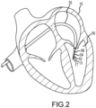
- a segment of an exemplary multi-electrode catheter 13 is shown in Figure 2 .
- catheter 13 extends into the left ventricle 50 of the patient's heart 10 through a transseptal sheath 35.
- transseptal sheath 35 The use of a transseptal approach to the left ventricle is well known and will be familiar to those of ordinary skill in the art, and need not be further described herein.
- catheter 13 can also be introduced into the heart 10 in any other suitable manner (e.g. , via epicardial access).
- Catheter 13 includes electrode 17 on its distal tip, as well as a plurality of additional measurement electrodes 52, 54, 56 spaced along its length in the illustrated embodiment. Typically, the spacing between adjacent electrodes will be known, though it should be understood that the electrodes may not be evenly spaced along catheter 13 or of equal size to each other. Since each of these electrodes 17, 52, 54, 56 lies within the patient, location data may be collected simultaneously for each of the electrodes by system 8.
- each of electrodes 17, 52, 54, and 56 can be used to gather electrophysiological data from the cardiac surface.
- the ordinarily skilled artisan will be familiar with various modalities for the acquisition and processing of electrophysiology data points (including, for example, both contact and non-contact electrophysiological mapping), such that further discussion thereof is not necessary to the understanding of the techniques disclosed herein.
- various techniques familiar in the art can be used to generate a graphical representation from the plurality of electrophysiology data points. Insofar as the ordinarily skilled artisan will appreciate how to create electrophysiology maps from electrophysiology data points, the aspects thereof will only be described herein to the extent necessary to understand the instant disclosure.
- an optional fixed reference electrode 31 (e.g ., attached to a wall of the heart 10) is shown on a second catheter 29.
- this electrode 31 may be stationary (e.g ., attached to or near the wall of the heart) or disposed in a fixed spatial relationship with the roving electrodes ( e.g. , electrodes 17), and thus may be referred to as a "navigational reference” or "local reference.”
- the fixed reference electrode 31 may be used in addition or alternatively to the surface reference electrode 21 described above.
- a coronary sinus electrode or other fixed electrode in the heart 10 can be used as a reference for measuring voltages and displacements; that is, as described below, fixed reference electrode 31 may define the origin of a coordinate system.
- Each surface electrode is coupled to a multiplex switch 24, and the pairs of surface electrodes are selected by software running on a computer 20, which couples the surface electrodes to a signal generator 25.
- switch 24 may be eliminated and multiple ( e.g. , three) instances of signal generator 25 may be provided, one for each measurement axis (that is, each surface electrode pairing).
- the computer 20 may comprise, for example, a conventional general-purpose computer, a special-purpose computer, a distributed computer, or any other type of computer.
- the computer 20 may comprise one or more processors 28, such as a single central processing unit (“CPU"), or a plurality of processing units, commonly referred to as a parallel processing environment, which may execute instructions to practice the various aspects described herein.
- processors 28 such as a single central processing unit (“CPU"), or a plurality of processing units, commonly referred to as a parallel processing environment, which may execute instructions to practice the various aspects described herein.
- three nominally orthogonal electric fields are generated by a series of driven and sensed electric dipoles (e.g ., surface electrode pairs 12/14, 18/19, and 16/22) in order to realize catheter navigation in a biological conductor.
- these orthogonal fields can be decomposed and any pairs of surface electrodes can be driven as dipoles to provide effective electrode triangulation.
- the electrodes 12, 14, 18, 19, 16, and 22 (or any number of electrodes) could be positioned in any other effective arrangement for driving a current to or sensing a current from an electrode in the heart.
- multiple electrodes could be placed on the back, sides, and/or belly of patient 11. Additionally, such non-orthogonal methodologies add to the flexibility of the system.
- the potentials measured across the roving electrodes resulting from a predetermined set of drive (source-sink) configurations may be combined algebraically to yield the same effective potential as would be obtained by simply driving a uniform current along the orthogonal axes.
- any two of the surface electrodes 12, 14, 16, 18, 19, 22 may be selected as a dipole source and drain with respect to a ground reference, such as belly patch 21, while the unexcited electrodes measure voltage with respect to the ground reference.
- the roving electrodes 17 placed in the heart 10 are exposed to the field from a current pulse and are measured with respect to ground, such as belly patch 21.
- the catheters within the heart 10 may contain more or fewer electrodes than the sixteen shown, and each electrode potential may be measured.
- at least one electrode may be fixed to the interior surface of the heart to form a fixed reference electrode 31, which is also measured with respect to ground, such as belly patch 21, and which may be defined as the origin of the coordinate system relative to which system 8 measures positions. Data sets from each of the surface electrodes, the internal electrodes, and the virtual electrodes may all be used to determine the location of the roving electrodes 17 within heart 10.
- the measured voltages may be used by system 8 to determine the location in three-dimensional space of the electrodes inside the heart, such as roving electrodes 17 relative to a reference location, such as reference electrode 31. That is, the voltages measured at reference electrode 31 may be used to define the origin of a coordinate system, while the voltages measured at roving electrodes 17 may be used to express the location of roving electrodes 17 relative to the origin.
- the coordinate system is a three-dimensional (x, y, z) Cartesian coordinate system, although other coordinate systems, such as polar, spherical, and cylindrical coordinate systems, are contemplated.
- the data used to determine the location of the electrode(s) within the heart is measured while the surface electrode pairs impress an electric field on the heart.
- the electrode data may also be used to create a respiration compensation value used to improve the raw location data for the electrode locations as described, for example, in United States Patent No. 7,263,397 .
- the electrode data may also be used to compensate for changes in the impedance of the body of the patient as described, for example, in United States Patent No. 7,885,707 .
- system 8 first selects a set of surface electrodes and then drives them with current pulses. While the current pulses are being delivered, electrical activity, such as the voltages measured with at least one of the remaining surface electrodes and in vivo electrodes, is measured and stored. Compensation for artifacts, such as respiration and/or impedance shifting, may be performed as indicated above.
- system 8 is the EnSite TM Velocity TM or EnSite Precision TM cardiac mapping and visualization system of Abbott Laboratories.
- Other localization systems may be used in connection with the present teachings, including for example the CARTO navigation and location system of Biosense Webster, Inc., the AURORA ® system of Northern Digital Inc., Sterotaxis' NIOBE ® Magnetic Navigation System, as well as MediGuide TM Technology from Abbott Laboratories.
- System 8 can therefore also include a signal quality module 58 (e.g., executing on processor 28) that can be used to determine signal quality scores.
- a signal quality module 58 e.g., executing on processor 28
- flowchart 300 may represent several exemplary steps that can be carried out by electroanatomical mapping system 8 of Figure 1 (e.g., by processor 28 and/or signal quality module 58).
- processor 28 and/or signal quality module 58 e.g., by processor 28 and/or signal quality module 58.
- the representative steps described below can be either hardware- or software-implemented.
- the term "signal processor" is used herein to describe both hardware- and software-based implementations of the teachings herein.
- the representative steps described below can be carried out in real time (e.g ., upon an intracardiac electrogram at the time of collection during an electrophysiology study) or as post-processing (e.g ., upon an intracardiac electrogram that was collected during an electrophysiology study performed at an earlier time). That is, the electrogram signal received in block 302 of Figure 3 can be a real-time electrogram signal or an electrogram signal that is part of a data set undergoing post processing.
- the signal processor receives information regarding the proximal stability of an electrophysiology catheter (e.g ., catheter 13) used to measure the electrogram signal received in block 302 at the time that signal was acquired.
- the proximal stability information is determined relative to an anatomical region, such as the cardiac surface being studied.
- the proximal stability information can include a distance between catheter 13 and the cardiac surface at the signal acquisition time.
- the distance between catheter 13 and the cardiac surface is measured using a geometric model of the anatomical region (e.g ., a cardiac geometry generated by electroanatomical mapping system 8), but it is also regarded as within the scope of the instant disclosure to measure the distance in other ways (e.g ., ultrasound, fluoroscopy).
- the proximal stability information can also include information regarding contact force between catheter 13 and the cardiac surface at the signal acquisition time.
- the proximal stability information can also include information regarding the velocity of catheter 13 at the signal acquisition time.
- the proximal stability information is used to generate a surface proximity signal quality parameter ("PS") and a contact force signal quality parameter ("CF").
- Other definitions of PS, including non-linear functions, are also contemplated as within the scope of the instant disclosure.
- F the contact force between catheter 13 and the cardiac surface.
- CF will also be set to 0 if catheter 13 lacks a contact force sensor.
- Other definitions of CF, including non-linear functions, are also contemplated as within the scope of the instant disclosure.
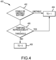
- the signal processor receives information regarding the temporal stability of the electrogram signal received in block 302. Then, in block 310, the temporal stability information is used to generate a temporal stability signal quality parameter ("TS").
- TS temporal stability signal quality parameter
- a stable rhythm e.g ., sinus rhythm; stable tachycardia
- TS 1 (block 404).
- a reproducibility threshold e.g ., 80%
- a graphical representation of the signal quality score can be output (e.g ., to display 23).
- a visual trace of the received electrogram signal is displayed using a color scale that corresponds to the computed quality score (e.g., high quality signals (e.g ., quality scores greater than or equal to about 90) can be colored white, while low quality signals (e.g. , quality scores less than or equal to about 80) can be colored red).
- the thresholds for high and low quality scores can be user-defined and/or user-adjustable.
- the numerical quality score can be shown on display 23 adjacent the corresponding visual trace of the received electrogram.
- progressively larger fonts can be used to display the numerical quality score as the quality score increases.
- Analogous font scaling can also be applied to other displayed text associated with the received electrogram (e.g ., a lead designator) in addition to or as an alternative to the displayed numerical quality score.
- the teachings above which are described with reference to a single electrogram, can be applied to multiple electrograms, thereby creating a signal quality map.
- the signal quality map can also be output as a graphical representation in a manner analogous to other electrophysiology maps, which techniques will be familiar to those of ordinary skill in the art.
- United States patent application publication no. 2015/0228254 discloses, among other things, the use of glyphs to graphically represent biological attributes.
- one or more glyph attributes e.g ., color, size, transparency, or the like
- the practitioner By providing the practitioner with a visual indication of signal quality, the practitioner will be able to ascertain, in real time, whether a particular electrophysiology data point should be stored and/or if catheter 13 should be repositioned prior to storing an electrophysiology data point.
- the techniques described herein can also be used to remove undesirable electrophysiology data points (e.g ., ectopic beats; noise artifacts) from an electrophysiology map in post-processing, thereby improving the quality of the electrophysiology map.
- All directional references e.g ., upper, lower, upward, downward, left, right, leftward, rightward, top, bottom, above, below, vertical, horizontal, clockwise, and counterclockwise
- Joinder references e.g. , attached, coupled, connected, and the like
Landscapes
- Health & Medical Sciences (AREA)
- Life Sciences & Earth Sciences (AREA)
- Engineering & Computer Science (AREA)
- Public Health (AREA)
- Medical Informatics (AREA)
- Physics & Mathematics (AREA)
- General Health & Medical Sciences (AREA)
- Pathology (AREA)
- Biomedical Technology (AREA)
- Biophysics (AREA)
- Surgery (AREA)
- Animal Behavior & Ethology (AREA)
- Molecular Biology (AREA)
- Heart & Thoracic Surgery (AREA)
- Veterinary Medicine (AREA)
- Artificial Intelligence (AREA)
- Physiology (AREA)
- Computer Vision & Pattern Recognition (AREA)
- Psychiatry (AREA)
- Signal Processing (AREA)
- Cardiology (AREA)
- Evolutionary Computation (AREA)
- Fuzzy Systems (AREA)
- Mathematical Physics (AREA)
- Human Computer Interaction (AREA)
- Databases & Information Systems (AREA)
- Data Mining & Analysis (AREA)
- Epidemiology (AREA)
- Primary Health Care (AREA)
- Radiology & Medical Imaging (AREA)
- Nuclear Medicine, Radiotherapy & Molecular Imaging (AREA)
- Measurement And Recording Of Electrical Phenomena And Electrical Characteristics Of The Living Body (AREA)
Claims (8)
- System (8) zur Bestimmung einer Signalqualität eines elektrophysiologischen Signals, das zu einer Erfassungszeit von einer anatomischen Region unter Verwendung eines elektrophysiologischen Katheters (13) gemessen wird, wobei das System umfasst:einen Signalqualitätsprozessor, konfiguriert zum:Empfangen von Informationen bezüglich einer proximalen Stabilität des elektrophysiologischen Katheters in Bezug auf die anatomische Region zu der Erfassungszeit als Eingabe, wobei die Informationen bezüglich der proximalen Stabilität umfassen:Informationen bezüglich eines Abstands zwischen dem elektrophysiologischen Katheter und der anatomischen Oberfläche zu der Erfassungszeit undInformationen bezüglich einer Kontaktkraft zwischen dem elektrophysiologischen Katheter und der anatomischen Oberfläche zu der Erfassungszeit;Empfangen von Informationen bezüglich einer temporalen Stabilität des elektrophysiologischen Signals als Eingabe undBerechnen eines numerischen Signalqualitätsscores als eine mathematische Funktion der Informationen bezüglich der proximalen Stabilität und der Informationen bezüglich der temporalen Stabilität; undeinen Abbildungsprozessor, der dazu konfiguriert ist, eine graphische Darstellung des numerischen Signalqualitätsscores auszugeben, wobei die graphische Darstellung des numerischen Signalqualitätsscores ein Ausgeben einer visuellen Spur des Elektrophysiologiesignals auf einer Anzeige (23) unter Verwendung einer Farbskala, die dem berechneten numerischen Qualitätsscore entspricht, umfasst.
- System nach Anspruch 1, wobei die Informationen bezüglich der proximalen Stabilität weiterhin Informationen bezüglich einer Geschwindigkeit des elektrophysiologischen Katheters zu der Erfassungszeit umfassen.
- System nach Anspruch 1, wobei der Abstand zwischen dem elektrophysiologischen Katheter und der anatomischen Oberfläche unter Verwendung eines geometrischen Modells der anatomischen Region gemessen wird.
- System nach Anspruch 1, wobei das Ausgeben einer graphischen Darstellung des Signalqualitätsscores ein Einfärben einer graphischen Darstellung des elektrophysiologischen Signals umfasst.
- System nach Anspruch 1, weiterhin konfiguriert zum Wiederholen von:Empfangen an dem Signalqualitätsprozessor:Informationen bezüglich der proximalen Stabilität eines elektrophysiologischen Katheters in Bezug auf eine anatomische Region, der dazu verwendet wird, des elektrophysiologische Signal zu einer Erfassungszeit des elektrophysiologischen Signals zu messen; undInformationen bezüglich der temporalen Stabilität des elektrophysiologischen Signals;Berechnen eines Signalqualitätsscores unter Verwendung der Informationen bezüglich der proximalen Stabilität und der Informationen bezüglich der temporalen Stabilität für eine Vielzahl von elektrophysiologischen Signalen, um eine Signalqualitätskarte zu erzeugen.
- System nach Anspruch 5, weiterhin konfiguriert zum Ausgeben einer graphischen Darstellung der Signalqualitätskarte.
- System nach Anspruch 6, wobei das Ausgeben einer graphischen Darstellung der Signalqualitätskarte ein Ausgeben der graphischen Darstellung der Signalqualitätskarte auf einem geometrischen Modell der anatomischen Region umfasst.
- System nach Anspruch 1, wobei die mathematische Funktion die Form QS = TS * [CF + (1 - CF) * PS] aufweist, wobei QS der Signalqualitätsscore ist; TS ein Parameter einer temporalen Stabilität eines Signals auf der Basis der Informationen bezüglich der temporalen Stabilität des elektrophysiologischen Signals ist; CF ein Kontaktkraftparameter auf der Basis der Informationen bezüglich einer Kontaktkraft zwischen dem elektrophysiologischen Katheter und der anatomischen Oberfläche zu der Erfassungszeit ist und PS ein Oberflächennähenparameter auf der Basis der Informationen bezüglich eines Abstands zwischen dem elektrophysiologischen Katheter und der anatomischen Oberfläche zu der Erfassungszeit ist.
Applications Claiming Priority (2)
| Application Number | Priority Date | Filing Date | Title |
|---|---|---|---|
| US201762534550P | 2017-07-19 | 2017-07-19 | |
| PCT/US2018/041654 WO2019018182A1 (en) | 2017-07-19 | 2018-07-11 | SYSTEM AND METHOD FOR ELECTROPHYSIOLOGICAL CARTOGRAPHY |
Publications (2)
| Publication Number | Publication Date |
|---|---|
| EP3609400A1 EP3609400A1 (de) | 2020-02-19 |
| EP3609400B1 true EP3609400B1 (de) | 2024-11-27 |
Family
ID=63145197
Family Applications (1)
| Application Number | Title | Priority Date | Filing Date |
|---|---|---|---|
| EP18752662.9A Active EP3609400B1 (de) | 2017-07-19 | 2018-07-11 | System zur elektrophysiologischen kartierung |
Country Status (3)
| Country | Link |
|---|---|
| US (1) | US11564606B2 (de) |
| EP (1) | EP3609400B1 (de) |
| WO (1) | WO2019018182A1 (de) |
Families Citing this family (4)
| Publication number | Priority date | Publication date | Assignee | Title |
|---|---|---|---|---|
| WO2020214962A1 (en) * | 2019-04-18 | 2020-10-22 | Acutus Medical, Inc. | System for creating a composite map |
| US11426126B2 (en) | 2019-05-23 | 2022-08-30 | Biosense Webster (Israel) Ltd. | Indicating electrode contact |
| US20240335169A1 (en) * | 2023-03-31 | 2024-10-10 | Biosense Webster (Israel) Ltd. | Methods and systems for displaying quality profiles points in an electro-anatomical map |
| US20250090077A1 (en) * | 2023-09-19 | 2025-03-20 | Boston Scientific Scimed, Inc. | Dynamic electroanatomical mapping |
Family Cites Families (11)
| Publication number | Priority date | Publication date | Assignee | Title |
|---|---|---|---|---|
| ATE160273T1 (de) | 1992-09-23 | 1997-12-15 | Endocardial Solutions Inc | Endokard-mapping system |
| US5662108A (en) | 1992-09-23 | 1997-09-02 | Endocardial Solutions, Inc. | Electrophysiology mapping system |
| US6939309B1 (en) | 1993-09-23 | 2005-09-06 | Endocardial Solutions, Inc. | Electrophysiology mapping system |
| US5697377A (en) | 1995-11-22 | 1997-12-16 | Medtronic, Inc. | Catheter mapping system and method |
| US7263397B2 (en) | 1998-06-30 | 2007-08-28 | St. Jude Medical, Atrial Fibrillation Division, Inc. | Method and apparatus for catheter navigation and location and mapping in the heart |
| US7885707B2 (en) | 2005-09-15 | 2011-02-08 | St. Jude Medical, Atrial Fibrillation Division, Inc. | Method of scaling navigation signals to account for impedance drift in tissue |
| US8948837B2 (en) | 2011-01-13 | 2015-02-03 | Rhythmia Medical, Inc. | Electroanatomical mapping |
| US9220425B2 (en) | 2012-09-17 | 2015-12-29 | Magnetecs Corp. | Method and apparatus for measuring biopotential and mapping ephaptic coupling employing a catheter with MOSFET sensor array |
| EP2934288A1 (de) | 2012-12-20 | 2015-10-28 | Boston Scientific Scimed, Inc. | Echtzeit-feedback für einen elektrodenkontakt während einer kartierung |
| WO2015026733A1 (en) | 2013-08-20 | 2015-02-26 | St. Jude Medical, Atrial Fibrillation Division, Inc. | System and method for generating electrophysiology maps |
| US20150228254A1 (en) * | 2014-02-07 | 2015-08-13 | St. Jude Medical, Cardiology Division, Inc. | Systems and Methods for Generating, Storing, and Displaying Anatomical Maps |
-
2018
- 2018-07-11 EP EP18752662.9A patent/EP3609400B1/de active Active
- 2018-07-11 WO PCT/US2018/041654 patent/WO2019018182A1/en not_active Ceased
- 2018-07-11 US US16/623,219 patent/US11564606B2/en active Active
Also Published As
| Publication number | Publication date |
|---|---|
| US20210145344A1 (en) | 2021-05-20 |
| EP3609400A1 (de) | 2020-02-19 |
| WO2019018182A1 (en) | 2019-01-24 |
| US11564606B2 (en) | 2023-01-31 |
Similar Documents
| Publication | Publication Date | Title |
|---|---|---|
| EP3206576B1 (de) | Verfahren und systeme zum mapping der lokalen erregungsleitungsgeschwindigkeit | |
| US9901271B2 (en) | System and method for analyzing biological signals and generating electrophysiology maps | |
| EP3261531B1 (de) | System und verfahren für elektrophysiologische kartierung in echtzeit | |
| US9220435B2 (en) | System and method for generating electrophysiology maps | |
| US12369835B2 (en) | System and method for electrophysiological mapping | |
| US11751794B2 (en) | System and method for mapping electrophysiological activation | |
| EP3344135B1 (de) | Verfahren und systeme zur abbildung der herzwiederherstellung | |
| EP3565459B1 (de) | System und verfahren zur unterscheidung adipösen gewebes von narbengewebe während einer elektrophysiologischen kartierung | |
| US20250025087A1 (en) | Method and system for visualizing ablation procedure data | |
| US20220409066A1 (en) | System and method for sorting electrophysiological signals from multi-dimensional catheters | |
| EP3609400B1 (de) | System zur elektrophysiologischen kartierung | |
| US11380029B2 (en) | System and method for mapping local activation times | |
| US11103177B2 (en) | System and method for mapping cardiac activity | |
| EP3500157B1 (de) | System und verfahren zur erzeugung von elektrophysiologischen karten |
Legal Events
| Date | Code | Title | Description |
|---|---|---|---|
| STAA | Information on the status of an ep patent application or granted ep patent |
Free format text: STATUS: UNKNOWN |
|
| STAA | Information on the status of an ep patent application or granted ep patent |
Free format text: STATUS: THE INTERNATIONAL PUBLICATION HAS BEEN MADE |
|
| PUAI | Public reference made under article 153(3) epc to a published international application that has entered the european phase |
Free format text: ORIGINAL CODE: 0009012 |
|
| STAA | Information on the status of an ep patent application or granted ep patent |
Free format text: STATUS: REQUEST FOR EXAMINATION WAS MADE |
|
| 17P | Request for examination filed |
Effective date: 20191112 |
|
| AK | Designated contracting states |
Kind code of ref document: A1 Designated state(s): AL AT BE BG CH CY CZ DE DK EE ES FI FR GB GR HR HU IE IS IT LI LT LU LV MC MK MT NL NO PL PT RO RS SE SI SK SM TR |
|
| AX | Request for extension of the european patent |
Extension state: BA ME |
|
| DAV | Request for validation of the european patent (deleted) | ||
| DAX | Request for extension of the european patent (deleted) | ||
| STAA | Information on the status of an ep patent application or granted ep patent |
Free format text: STATUS: EXAMINATION IS IN PROGRESS |
|
| 17Q | First examination report despatched |
Effective date: 20220211 |
|
| P01 | Opt-out of the competence of the unified patent court (upc) registered |
Effective date: 20230616 |
|
| REG | Reference to a national code |
Ref country code: DE Ref legal event code: R079 Free format text: PREVIOUS MAIN CLASS: A61B0005042000 Ipc: A61B0005060000 Ref country code: DE Ref legal event code: R079 Ref document number: 602018076978 Country of ref document: DE Free format text: PREVIOUS MAIN CLASS: A61B0005042000 Ipc: A61B0005060000 |
|
| GRAP | Despatch of communication of intention to grant a patent |
Free format text: ORIGINAL CODE: EPIDOSNIGR1 |
|
| STAA | Information on the status of an ep patent application or granted ep patent |
Free format text: STATUS: GRANT OF PATENT IS INTENDED |
|
| RIC1 | Information provided on ipc code assigned before grant |
Ipc: G16H 50/20 20180101ALN20240603BHEP Ipc: A61B 5/339 20210101ALI20240603BHEP Ipc: A61B 5/287 20210101ALI20240603BHEP Ipc: A61B 5/06 20060101AFI20240603BHEP |
|
| INTG | Intention to grant announced |
Effective date: 20240621 |
|
| RIC1 | Information provided on ipc code assigned before grant |
Ipc: G16H 50/20 20180101ALN20240610BHEP Ipc: A61B 5/339 20210101ALI20240610BHEP Ipc: A61B 5/287 20210101ALI20240610BHEP Ipc: A61B 5/06 20060101AFI20240610BHEP |
|
| RIN1 | Information on inventor provided before grant (corrected) |
Inventor name: MARKOVITZ, CRAIG Inventor name: CASSET, CYRILLE Inventor name: JIANG, CHUNLAN Inventor name: RICHER, LOUIS-PHILIPPE Inventor name: MANGUAL-SOTO, JAN, O. |
|
| GRAS | Grant fee paid |
Free format text: ORIGINAL CODE: EPIDOSNIGR3 |
|
| GRAA | (expected) grant |
Free format text: ORIGINAL CODE: 0009210 |
|
| STAA | Information on the status of an ep patent application or granted ep patent |
Free format text: STATUS: THE PATENT HAS BEEN GRANTED |
|
| AK | Designated contracting states |
Kind code of ref document: B1 Designated state(s): AL AT BE BG CH CY CZ DE DK EE ES FI FR GB GR HR HU IE IS IT LI LT LU LV MC MK MT NL NO PL PT RO RS SE SI SK SM TR |
|
| REG | Reference to a national code |
Ref country code: GB Ref legal event code: FG4D |
|
| REG | Reference to a national code |
Ref country code: CH Ref legal event code: EP |
|
| REG | Reference to a national code |
Ref country code: IE Ref legal event code: FG4D |
|
| REG | Reference to a national code |
Ref country code: DE Ref legal event code: R096 Ref document number: 602018076978 Country of ref document: DE |
|
| REG | Reference to a national code |
Ref country code: LT Ref legal event code: MG9D |
|
| REG | Reference to a national code |
Ref country code: NL Ref legal event code: MP Effective date: 20241127 |
|
| PG25 | Lapsed in a contracting state [announced via postgrant information from national office to epo] |
Ref country code: IS Free format text: LAPSE BECAUSE OF FAILURE TO SUBMIT A TRANSLATION OF THE DESCRIPTION OR TO PAY THE FEE WITHIN THE PRESCRIBED TIME-LIMIT Effective date: 20250327 Ref country code: HR Free format text: LAPSE BECAUSE OF FAILURE TO SUBMIT A TRANSLATION OF THE DESCRIPTION OR TO PAY THE FEE WITHIN THE PRESCRIBED TIME-LIMIT Effective date: 20241127 Ref country code: PT Free format text: LAPSE BECAUSE OF FAILURE TO SUBMIT A TRANSLATION OF THE DESCRIPTION OR TO PAY THE FEE WITHIN THE PRESCRIBED TIME-LIMIT Effective date: 20250327 |
|
| PG25 | Lapsed in a contracting state [announced via postgrant information from national office to epo] |
Ref country code: FI Free format text: LAPSE BECAUSE OF FAILURE TO SUBMIT A TRANSLATION OF THE DESCRIPTION OR TO PAY THE FEE WITHIN THE PRESCRIBED TIME-LIMIT Effective date: 20241127 Ref country code: NL Free format text: LAPSE BECAUSE OF FAILURE TO SUBMIT A TRANSLATION OF THE DESCRIPTION OR TO PAY THE FEE WITHIN THE PRESCRIBED TIME-LIMIT Effective date: 20241127 |
|
| REG | Reference to a national code |
Ref country code: AT Ref legal event code: MK05 Ref document number: 1744895 Country of ref document: AT Kind code of ref document: T Effective date: 20241127 |
|
| PG25 | Lapsed in a contracting state [announced via postgrant information from national office to epo] |
Ref country code: BG Free format text: LAPSE BECAUSE OF FAILURE TO SUBMIT A TRANSLATION OF THE DESCRIPTION OR TO PAY THE FEE WITHIN THE PRESCRIBED TIME-LIMIT Effective date: 20241127 |
|
| PG25 | Lapsed in a contracting state [announced via postgrant information from national office to epo] |
Ref country code: ES Free format text: LAPSE BECAUSE OF FAILURE TO SUBMIT A TRANSLATION OF THE DESCRIPTION OR TO PAY THE FEE WITHIN THE PRESCRIBED TIME-LIMIT Effective date: 20241127 |
|
| PG25 | Lapsed in a contracting state [announced via postgrant information from national office to epo] |
Ref country code: NO Free format text: LAPSE BECAUSE OF FAILURE TO SUBMIT A TRANSLATION OF THE DESCRIPTION OR TO PAY THE FEE WITHIN THE PRESCRIBED TIME-LIMIT Effective date: 20250227 |
|
| PG25 | Lapsed in a contracting state [announced via postgrant information from national office to epo] |
Ref country code: LV Free format text: LAPSE BECAUSE OF FAILURE TO SUBMIT A TRANSLATION OF THE DESCRIPTION OR TO PAY THE FEE WITHIN THE PRESCRIBED TIME-LIMIT Effective date: 20241127 Ref country code: AT Free format text: LAPSE BECAUSE OF FAILURE TO SUBMIT A TRANSLATION OF THE DESCRIPTION OR TO PAY THE FEE WITHIN THE PRESCRIBED TIME-LIMIT Effective date: 20241127 Ref country code: GR Free format text: LAPSE BECAUSE OF FAILURE TO SUBMIT A TRANSLATION OF THE DESCRIPTION OR TO PAY THE FEE WITHIN THE PRESCRIBED TIME-LIMIT Effective date: 20250228 |
|
| PG25 | Lapsed in a contracting state [announced via postgrant information from national office to epo] |
Ref country code: PL Free format text: LAPSE BECAUSE OF FAILURE TO SUBMIT A TRANSLATION OF THE DESCRIPTION OR TO PAY THE FEE WITHIN THE PRESCRIBED TIME-LIMIT Effective date: 20241127 |
|
| PG25 | Lapsed in a contracting state [announced via postgrant information from national office to epo] |
Ref country code: RS Free format text: LAPSE BECAUSE OF FAILURE TO SUBMIT A TRANSLATION OF THE DESCRIPTION OR TO PAY THE FEE WITHIN THE PRESCRIBED TIME-LIMIT Effective date: 20250227 |
|
| PG25 | Lapsed in a contracting state [announced via postgrant information from national office to epo] |
Ref country code: SM Free format text: LAPSE BECAUSE OF FAILURE TO SUBMIT A TRANSLATION OF THE DESCRIPTION OR TO PAY THE FEE WITHIN THE PRESCRIBED TIME-LIMIT Effective date: 20241127 |
|
| PG25 | Lapsed in a contracting state [announced via postgrant information from national office to epo] |
Ref country code: DK Free format text: LAPSE BECAUSE OF FAILURE TO SUBMIT A TRANSLATION OF THE DESCRIPTION OR TO PAY THE FEE WITHIN THE PRESCRIBED TIME-LIMIT Effective date: 20241127 |
|
| PGFP | Annual fee paid to national office [announced via postgrant information from national office to epo] |
Ref country code: GB Payment date: 20250612 Year of fee payment: 8 |
|
| PG25 | Lapsed in a contracting state [announced via postgrant information from national office to epo] |
Ref country code: EE Free format text: LAPSE BECAUSE OF FAILURE TO SUBMIT A TRANSLATION OF THE DESCRIPTION OR TO PAY THE FEE WITHIN THE PRESCRIBED TIME-LIMIT Effective date: 20241127 |
|
| PGFP | Annual fee paid to national office [announced via postgrant information from national office to epo] |
Ref country code: FR Payment date: 20250612 Year of fee payment: 8 |
|
| PG25 | Lapsed in a contracting state [announced via postgrant information from national office to epo] |
Ref country code: RO Free format text: LAPSE BECAUSE OF FAILURE TO SUBMIT A TRANSLATION OF THE DESCRIPTION OR TO PAY THE FEE WITHIN THE PRESCRIBED TIME-LIMIT Effective date: 20241127 |
|
| PG25 | Lapsed in a contracting state [announced via postgrant information from national office to epo] |
Ref country code: SK Free format text: LAPSE BECAUSE OF FAILURE TO SUBMIT A TRANSLATION OF THE DESCRIPTION OR TO PAY THE FEE WITHIN THE PRESCRIBED TIME-LIMIT Effective date: 20241127 |
|
| PG25 | Lapsed in a contracting state [announced via postgrant information from national office to epo] |
Ref country code: CZ Free format text: LAPSE BECAUSE OF FAILURE TO SUBMIT A TRANSLATION OF THE DESCRIPTION OR TO PAY THE FEE WITHIN THE PRESCRIBED TIME-LIMIT Effective date: 20241127 |
|
| REG | Reference to a national code |
Ref country code: DE Ref legal event code: R097 Ref document number: 602018076978 Country of ref document: DE |
|
| PG25 | Lapsed in a contracting state [announced via postgrant information from national office to epo] |
Ref country code: SE Free format text: LAPSE BECAUSE OF FAILURE TO SUBMIT A TRANSLATION OF THE DESCRIPTION OR TO PAY THE FEE WITHIN THE PRESCRIBED TIME-LIMIT Effective date: 20241127 |
|
| PLBE | No opposition filed within time limit |
Free format text: ORIGINAL CODE: 0009261 |
|
| STAA | Information on the status of an ep patent application or granted ep patent |
Free format text: STATUS: NO OPPOSITION FILED WITHIN TIME LIMIT |
|
| REG | Reference to a national code |
Ref country code: CH Ref legal event code: L10 Free format text: ST27 STATUS EVENT CODE: U-0-0-L10-L00 (AS PROVIDED BY THE NATIONAL OFFICE) Effective date: 20251008 |
|
| PGFP | Annual fee paid to national office [announced via postgrant information from national office to epo] |
Ref country code: DE Payment date: 20250616 Year of fee payment: 8 |
|
| PGFP | Annual fee paid to national office [announced via postgrant information from national office to epo] |
Ref country code: IT Payment date: 20250714 Year of fee payment: 8 |
|
| 26N | No opposition filed |
Effective date: 20250828 |
|
| REG | Reference to a national code |
Ref country code: CH Ref legal event code: H13 Free format text: ST27 STATUS EVENT CODE: U-0-0-H10-H13 (AS PROVIDED BY THE NATIONAL OFFICE) Effective date: 20260224 |
|
| PG25 | Lapsed in a contracting state [announced via postgrant information from national office to epo] |
Ref country code: LU Free format text: LAPSE BECAUSE OF NON-PAYMENT OF DUE FEES Effective date: 20250711 |
|
| REG | Reference to a national code |
Ref country code: BE Ref legal event code: MM Effective date: 20250731 |
|
| PG25 | Lapsed in a contracting state [announced via postgrant information from national office to epo] |
Ref country code: BE Free format text: LAPSE BECAUSE OF NON-PAYMENT OF DUE FEES Effective date: 20250731 |