EP3609156B1 - Verfahren zur verbesserten cyber-sicherheit mit frequenztrennung - Google Patents
Verfahren zur verbesserten cyber-sicherheit mit frequenztrennung Download PDFInfo
- Publication number
- EP3609156B1 EP3609156B1 EP19184891.0A EP19184891A EP3609156B1 EP 3609156 B1 EP3609156 B1 EP 3609156B1 EP 19184891 A EP19184891 A EP 19184891A EP 3609156 B1 EP3609156 B1 EP 3609156B1
- Authority
- EP
- European Patent Office
- Prior art keywords
- node
- communication
- frequency
- data link
- concentrator
- Prior art date
- Legal status (The legal status is an assumption and is not a legal conclusion. Google has not performed a legal analysis and makes no representation as to the accuracy of the status listed.)
- Active
Links
Images



Classifications
-
- H—ELECTRICITY
- H04—ELECTRIC COMMUNICATION TECHNIQUE
- H04B—TRANSMISSION
- H04B1/00—Details of transmission systems, not covered by a single one of groups H04B3/00 - H04B13/00; Details of transmission systems not characterised by the medium used for transmission
- H04B1/69—Spread spectrum techniques
- H04B1/713—Spread spectrum techniques using frequency hopping
- H04B1/7136—Arrangements for generation of hop frequencies, e.g. using a bank of frequency sources, using continuous tuning or using a transform
-
- G—PHYSICS
- G06—COMPUTING OR CALCULATING; COUNTING
- G06F—ELECTRIC DIGITAL DATA PROCESSING
- G06F21/00—Security arrangements for protecting computers, components thereof, programs or data against unauthorised activity
- G06F21/50—Monitoring users, programs or devices to maintain the integrity of platforms, e.g. of processors, firmware or operating systems
- G06F21/55—Detecting local intrusion or implementing counter-measures
- G06F21/554—Detecting local intrusion or implementing counter-measures involving event detection and direct action
-
- G—PHYSICS
- G06—COMPUTING OR CALCULATING; COUNTING
- G06F—ELECTRIC DIGITAL DATA PROCESSING
- G06F21/00—Security arrangements for protecting computers, components thereof, programs or data against unauthorised activity
- G06F21/70—Protecting specific internal or peripheral components, in which the protection of a component leads to protection of the entire computer
- G06F21/82—Protecting input, output or interconnection devices
- G06F21/85—Protecting input, output or interconnection devices interconnection devices, e.g. bus-connected or in-line devices
-
- H—ELECTRICITY
- H04—ELECTRIC COMMUNICATION TECHNIQUE
- H04B—TRANSMISSION
- H04B1/00—Details of transmission systems, not covered by a single one of groups H04B3/00 - H04B13/00; Details of transmission systems not characterised by the medium used for transmission
- H04B1/69—Spread spectrum techniques
- H04B1/713—Spread spectrum techniques using frequency hopping
- H04B1/7143—Arrangements for generation of hop patterns
-
- H—ELECTRICITY
- H04—ELECTRIC COMMUNICATION TECHNIQUE
- H04K—SECRET COMMUNICATION; JAMMING OF COMMUNICATION
- H04K1/00—Secret communication
- H04K1/003—Secret communication by varying carrier frequency at or within predetermined or random intervals
-
- H—ELECTRICITY
- H04—ELECTRIC COMMUNICATION TECHNIQUE
- H04K—SECRET COMMUNICATION; JAMMING OF COMMUNICATION
- H04K3/00—Jamming of communication; Counter-measures
- H04K3/20—Countermeasures against jamming
- H04K3/22—Countermeasures against jamming including jamming detection and monitoring
- H04K3/224—Countermeasures against jamming including jamming detection and monitoring with countermeasures at transmission and/or reception of the jammed signal, e.g. stopping operation of transmitter or receiver, nulling or enhancing transmitted power in direction of or at frequency of jammer
- H04K3/226—Selection of non-jammed channel for communication
-
- H—ELECTRICITY
- H04—ELECTRIC COMMUNICATION TECHNIQUE
- H04L—TRANSMISSION OF DIGITAL INFORMATION, e.g. TELEGRAPHIC COMMUNICATION
- H04L63/00—Network architectures or network communication protocols for network security
- H04L63/02—Network architectures or network communication protocols for network security for separating internal from external traffic, e.g. firewalls
- H04L63/0281—Proxies
-
- H—ELECTRICITY
- H04—ELECTRIC COMMUNICATION TECHNIQUE
- H04L—TRANSMISSION OF DIGITAL INFORMATION, e.g. TELEGRAPHIC COMMUNICATION
- H04L63/00—Network architectures or network communication protocols for network security
- H04L63/14—Network architectures or network communication protocols for network security for detecting or protecting against malicious traffic
- H04L63/1408—Network architectures or network communication protocols for network security for detecting or protecting against malicious traffic by monitoring network traffic
- H04L63/1425—Traffic logging, e.g. anomaly detection
-
- H—ELECTRICITY
- H04—ELECTRIC COMMUNICATION TECHNIQUE
- H04L—TRANSMISSION OF DIGITAL INFORMATION, e.g. TELEGRAPHIC COMMUNICATION
- H04L63/00—Network architectures or network communication protocols for network security
- H04L63/14—Network architectures or network communication protocols for network security for detecting or protecting against malicious traffic
- H04L63/1441—Countermeasures against malicious traffic
-
- H—ELECTRICITY
- H04—ELECTRIC COMMUNICATION TECHNIQUE
- H04L—TRANSMISSION OF DIGITAL INFORMATION, e.g. TELEGRAPHIC COMMUNICATION
- H04L69/00—Network arrangements, protocols or services independent of the application payload and not provided for in the other groups of this subclass
- H04L69/14—Multichannel or multilink protocols
-
- H—ELECTRICITY
- H04—ELECTRIC COMMUNICATION TECHNIQUE
- H04K—SECRET COMMUNICATION; JAMMING OF COMMUNICATION
- H04K2203/00—Jamming of communication; Countermeasures
- H04K2203/10—Jamming or countermeasure used for a particular application
- H04K2203/14—Jamming or countermeasure used for a particular application for the transfer of light or images, e.g. for video-surveillance, for television or from a computer screen
-
- H—ELECTRICITY
- H04—ELECTRIC COMMUNICATION TECHNIQUE
- H04W—WIRELESS COMMUNICATION NETWORKS
- H04W12/00—Security arrangements; Authentication; Protecting privacy or anonymity
- H04W12/02—Protecting privacy or anonymity, e.g. protecting personally identifiable information [PII]
-
- H—ELECTRICITY
- H04—ELECTRIC COMMUNICATION TECHNIQUE
- H04W—WIRELESS COMMUNICATION NETWORKS
- H04W12/00—Security arrangements; Authentication; Protecting privacy or anonymity
- H04W12/08—Access security
Definitions
- the present disclosure relates to aircraft engines, more particularly a control system for aircraft engines and a method for controlling an aircraft engine.
- Aircrafts such as commercial and military aircraft, include aerospace control systems that control and monitor aircraft engines.
- the aerospace control systems may control and/or monitor aerospace control system components such as, for example, aircraft engine pressure sensors, temperature sensors, solenoids, and actuators.
- the aerospace control systems may also control and/or manage other aircraft engine parts and/or functionality.
- aerospace control systems may assist in ensuring optimum aircraft engine efficiencies during flight are achieved by receiving various flight condition information and controlling various aircraft engine operations, such as fuel flow, valve positions, and others.
- Aerospace control systems may include a full authority digital engine controller (“FADEC”) that includes an electronic engine controller (“EEC”) or engine control unit (“ECU").
- FADEC full authority digital engine controller
- EEC electronic engine controller
- ECU engine control unit
- the FADEC may further include a central processing unit (“CPU”), memory, and a data bus to communicate with other aircraft engine components, such as aircraft engine sensors and actuators.
- the FADEC may include maintenance ports and/or communication ports. These ports include connector interfaces for various connector types such as Ethernet ports, serial ports, and/or universal serial bus (“USB”) ports, among others, that may connect with different parts of the aircraft.
- United States patent application US 2015/0363981 A1 discloses a system and method of transmitting data from an aircraft includes a PC card that acquires aircraft data and transmits the aircraft data over a radio frequency communications signal into the skin of the aircraft, which radiates the radio frequency communications signal to a location remote from the aircraft.
- Aerospace control systems may include a centralized (or federated) control system (“CCS”) architecture design or a distributed control system (“DCS”) architecture design.
- Aerospace control systems incorporating a CCS architecture design include a FADEC with a CPU that handles all processing functions.
- the FADEC also includes additional electronic circuitry required for data acquisition (such as from the various sensors) as well as signal conditioning.
- interface (e.g., wire) harnesses may be used to connect the various aerospace control system components, such as sensors and/or actuators to the FADEC.
- An aerospace control system incorporating a DCS architecture design may not require a FADEC with this additional circuitry.
- the various aerospace control system components e.g., sensors and/or actuators
- the various aerospace control system components include local processing capabilities that can relay information to the FADEC's CPU.
- a DCS architecture design includes digital communication between the FADEC and the various sensors and/or actuators, rather than interface harnesses.
- Aerospace control systems with a DCS architecture design may also employ a data concentrator (e.g., concentrator node) that provides for communication with both components that do not include local processing capabilities as well as components that do include local processing capabilities. The data concentrator facilitates the communications between the FADEC and the nodes.
- a data concentrator e.g., concentrator node
- aerospace architectures have vulnerabilities during operation in a cyber-hostile environment.
- threats from a cyber attack can come from software loaded onto the FADEC via one of the FADEC's maintenance or communication ports, for example. Threats may also come from hacking into access points over communication links between the FADEC and other parts of the aerospace control system, such as sensors and actuators.
- aerospace architectures are vulnerable to "hardware hacks," where hardware, such as the FADEC or a communication link, is physically altered to allow access to the aerospace control system. As such, there are opportunities to address these and other vulnerabilities with aerospace control systems.
- the present disclosure provides a control system for an aircraft engine, and a method for controlling an aircraft engine, as set out in the appended claims.
- the present disclosure provides a control system for an aircraft engine comprising: a first data link; a second data link; a control node comprising a first processor; and a concentrator node comprising a second processor and operably coupled to the control node via the first data link and via the second data link, wherein the control node communicates with the concentrator node over the first data link at a first communication frequency and a first communication rate; and changes the first communication frequency in response to at least one event, wherein the control node is configured to send a frequency change indication to the concentrator node, and wherein the concentrator node is configured to communicate with the control node at the changed first communication frequency in response to receiving the frequency change indication, and wherein the control node is configured to send the frequency change indication to the concentrator node over the second data link.
- the present disclosure provides a method for controlling an aircraft engine, the method comprising: communicating, by a first processor of a control node, with a second processor of a concentrator node over a first data link at a first communication frequency at a first communication rate; communicating, by the first processor of the control node, with the second processor of the concentrator node over a second data link at a second communication rate that is different than the first communication rate; detecting, by the first processor of the control node, a communication anomaly over the first data link; changing, by the first processor of the control node, the first communication frequency in response to the detected communication anomaly; communicating, by the first processor of the control node, with the second processor of the concentrator node over the first data link at the changed first communication frequency; transmitting, by the control node a frequency change indication to the concentrator node; and communicating, by the concentrator node with the control node, at the changed first communication frequency in response to receiving the frequency change indication, wherein the control node transmits the frequency
- FIG. 1 illustrates an example aircraft 100 with turbine engines 102, 104.
- Each turbine engine may be controlled by an engine control system, which is discussed in more detail with respect to FIG. 2 .
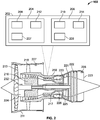
- FIG. 2 illustrates the aircraft engine 102 of the example aircraft 100 of FIG. 1 in more detail.
- the aircraft engine 102 includes an engine control system 202 that includes a control node 204 and a concentrator node 206.
- the control node may be, for example, a FADEC.
- Each of the control node 204 and concentrator node 206 includes electronic circuitry.
- the electronic circuitry may include one or more processing units 208, 210.
- a processing unit can be, for example, a microprocessor, an execution unit or "core" on a microprocessor chip, a digital signal processor (DSP), a soft or hard core within a field-programmable gate arrays (FPGA), a processor within an application-specific integrated circuit (ASIC), a general processing unit (GPU), a commercial off the shelf (COTS) processor, or any other suitable processor.
- DSP digital signal processor
- FPGA field-programmable gate arrays
- ASIC application-specific integrated circuit
- GPU general processing unit
- COTS commercial off the shelf
- Each of the control node 204 and concentrator node 206 may include instruction memory 212, 214, respectively.
- Instruction memory 212, 214 can store instructions that can be accessed (e.g., read) and executed by processing units 208, 210, respectively.
- each of instruction memory 212, 214 can be a non-transitory, computer-readable storage medium such as a read-only memory (ROM), an electrically erasable programmable read-only memory (EEPROM), flash memory, a removable disk, CD-ROM, any non-volatile memory, or any other suitable memory.
- ROM read-only memory
- EEPROM electrically erasable programmable read-only memory
- flash memory a removable disk
- CD-ROM any non-volatile memory, or any other suitable memory.
- Each of the control node 204 and concentrator node 206 may also include working memory 207, 209, respectively.
- Processing units 208, 210 can store data to, and read data from, working memory 207, 209, respectively.
- processing units 208, 210 can store a working set of instructions to working memory 207, 209, such as instructions loaded from instruction memory 212, 214, respectively.
- Processing units 208, 210 can also use working memory 208, 210, respectively, to store dynamic data.
- FIG. 2 further illustrates, as part of aircraft engine 102, a fan 213, a first compressor 216, a second compressor 217, turbines 220, 221, 222, propulsion nozzle 223, and fan duct 211.
- the fan duct 211 is supported by guide vanes 215 extending from engine platform 250.
- the fan 213 is driven by a first shaft 224 connected to fan 213.
- First compressor 216 is driven by turbine 221 via a second shaft 225
- second compressor 217 is driven by turbine 220 via a third shaft 226.
- Engine control system 202 may also be communicatively coupled to one or more engine control devices 227, 228, 232 such as sensors (e.g., pressure or speed transducer) or actuators.
- FIG. 3 illustrates a block diagram of an engine control system 300 that includes a control node 302, a concentrator node 304, one or more sensors 306, one or more actuators 308, and one or more smart sensors 310.
- Concentrator node 304 is communicatively coupled to each of one or more sensors 306, one or more actuators 308, and one or more smart sensors 310 over communication link 312.
- concentrator node 304 may communicate with each of one or more sensors 306, one or more actuators 308, and one or more smart sensors 310 over communication link 312, which may be a fiber optic communication link, an Ethernet link, or any other suitable link.
- Communication link 312 may employ, for example, an interconnect bus architecture. Communication between the control node 302 and the sensor 306, 310 and the actuator 308 in the embodiment shown in Fig. 3 is via the concentrator node.
- Sensor 306 may be, for example, an optical sensor, a pressure sensor, a temperature sensor, or any other suitable sensor. Sensor 306 may provide sensor readings over communication link 312 to concentrator node 306. Smart sensor 310 may be a sensor that also provides processing capability. For example, rather than merely providing raw sensor readings, smart sensor 310 may provide calibrated readings over communication link 312 and/or may bypass the concentrator node 304 and communicate with the control node 302 using the same methodology as employed by the concentrator node 304. In some examples, concentrator node 306 includes drivers that can connect via a direct link (or over a bus architecture), such as an optical or electrical harness, to one or more actuators 308.
- a direct link or over a bus architecture
- actuators 308 such as an optical or electrical harness
- Concentrator node 304 is also communicatively coupled to control node 302 over at least a first communication link 314.
- the first communication link 314 may be fiber optic, Ethernet, hardwired and/or wireless.
- First communication link 314 may be a fiber optic link, such as one using multi-mode optical fiber ( e.g., a multi-mode fiber optic link), for example.
- Control node 302 is operable to transmit to, and receive data from, concentrator node 304 over first communication link 314.
- concentrator node 304 may send sensor readings, such as from one or more sensors 306 or one or more smart sensors 310, to control node 302 over first communication link 314.
- control node 302 may send control messages to concentrator node 304, such as control messages to control one or more actuators 308, over first communication link 314.
- communications over first communication link 314 are encrypted.
- Control node 302 and concentrator node 304 may establish a frequency within a supported frequency band to use for communications over the first communication link 314. For example, control node 302 and communication node 304 may begin communications at a default, or startup, frequency.
- Control node 302 is operable to change the frequency used for communications over first communication link 304.
- control node 302 changes the frequency when an event, such as an anomaly, has been detected.
- the event can be, for example, a disruption to communications, an unexpected increase in communication traffic, a particular communication traffic pattern, one or more sensor readings, a detected cyber security threat, a control system intrusion, a detection of malicious activity, or any other indication.
- the event can be a change in light properties of the light travelling over the fiber optic link.
- the event can be a change to one or more Stokes parameters based on the light travelling over the fiber optic link.
- Control node 302 may detect the event, or may receive an indication of the detected event, such as from concentrator node 304. In some examples, upon detection or indication of the event, control node 302 may send a message to concentrator node 304 to change the communication frequency. For example, control node 302 may send a message indicating the frequency to be used (e.g. specifying the frequency or referencing a previously provided table/vector). The message may also indicate when the new frequency is to be used. For example, the message may indicate that the new frequency is to be used immediately, or that it is to be used beginning at a particular time. In some examples, the message indicates ranges of time in which a frequency is to be used.
- control node 302 and concentrator node 304 are configured to automatically change the frequency periodically.
- control node 302 and concentrator node 304 may be configured to change the frequency after an amount of time (e.g., every 15 minutes, every hour, every day, etc.).
- control node 302 and concentrator node 304 maintain a same table of frequencies (vector) within a frequency band. Each table includes frequencies in a same order. Control node 302 may indicate to concentrator node 304 which frequency to use by identifying, in a message, an indicia (reference) associated with a frequency in the table. For example, the number "3" would indicate the third entry in the frequency table.
- control node 302 sends to concentrator node 304 a selection number I/O vector, which is a value that determines what frequency within a frequency band to communicate across.
- the selection number I/O vector may include a listing of frequencies to communicate with.
- the selection number I/O vector may include a listing of offsets within a frequency band.
- control node 302 is configured to continue transmitting at a current frequency while also transmitting at a new frequency. For example, upon detection of an event, control node 302 may transmit data, such as "dummy data," at the current frequency which is ignored by concentrator node 304. Control node 302 may transmit valid data, which is not to be ignored, at a new frequency to concentrator node 304. Similarly, concentrator node 304 may transmit data that is to be ignored at a current frequency, while transmitting valid data at a new frequency.
- first communication link 314 includes multiple fiber optic links, such as in a braided ring.
- Each of the fiber optic links may be configured to operate over differing wavelength ranges. For example, one fiber optic link may operate in a range of wavelengths from 800 to 1500 nanometers, while a second fiber optic link may operate in a range of wavelengths from 300 to 500 nanometers.
- control node 302 and concentrator node 304 are configured to send valid data over one fiber optic link, while sending "dummy data" on another fiber optic link. In some examples, control node 302 and concentrator node 304 are configured to change the link over which the valid data is sent over.
- control node 302 and concentrator node 304 may change the link over which valid data is sent over automatically, periodically, or based on messaging (e.g ., the control node 302 sends a message indicating such change to the concentrator node 304).
- one fiber optic link operates over the ultraviolet (UV) parts of the frequency spectrum, while the other operates over the infrared (IR) parts of the frequency spectrum.
- concentrator node 304 is also communicatively coupled to control node 302 over a second communication link 316.
- Second communication link 316 may also be a fiber optic link, a hardwired link, such as an Ethernet link or wireless.
- control node 302 is operable to transmit to, and receive data from, concentrator node 304 over second communication link 316.
- communications over second communication link 316 are encrypted.
- control node 302 and concentrator node 304 may communicate over different communication networks at different speeds.
- first communication link 314 is a fiber optic link
- communication speeds may be in the range of 1 to 10 gigabits per second (GBps).
- second communication link 316 is an Ethernet link
- communication speeds may be in the range of 10 to 100 megabits per second (MBps).
- control node 302 and concentrator node 304 would be operable to communicate simultaneously over a fiber optic link at 10 GBps, and over an Ethernet link at 100 MBps.
- control node 302 can change the communication speed over any communication link, such as the first communication link 314 or the second communication link. For example, assuming that the first communication link 314 is a fiber optic link, control node 302 can send a message to concentrator node 304 to change the communication speed over the first communication link from 1 GBps to 10 GBps.
- Control node 302 and concentrator node 304 may be configured to send redundant data over second communication link 316.
- the data may be redundant to the data sent over the first communication link 314.
- control node 302 may send a same message to concentrator node 304 over both first communication link 314 and second communication link 316.
- concentrator node 304 may send redundant information to control node 302 over both first communication link 314 and second communication link 316.
- concentrator node 304 verifies (e.g., checks) that the data received over first communication link 314 and second communication link 316 matches (e.g., is in fact redundant of each other). If the data verifies as redundant, concentrator node 304 takes appropriate action. For example, if the data indicates a request for sensor data, concentrator node 304 reads the appropriate sensor and sends the sensor readings to control node 302. Otherwise, if the data does not match (e.g., a data verification error), concentrator node 304 may take precautionary measures.
- Precautionary measures may include, for example, concentrator node 304 ignoring the data (e.g ., disregarding the data that failed verification). In some examples, concentrator node 304 may send a message to control node 304 that the data did not verify. Control node 302 may then give an indication of such failure, such as by causing an error light ( e.g., led) to turn on, or by providing an error message to a user of the control system. In some examples, in response to detecting a data verification error, concentrator node 304 may message control node 302 that the frequency being used to communicate over first communication link 314 is to be changed. Control node 302 and concentrator node 304 may then begin communicating with each other over first communication link 314 at the new frequency.
- concentrator node 304 may send a message to control node 304 that the data did not verify. Control node 302 may then give an indication of such failure, such as by causing an error light (e.g., led) to turn on, or by providing an
- FIG. 4 is a flowchart of an example method 400 that can be carried out by, for example, the engine control system 300 of FIG. 3 .
- the methods are described with reference to illustrated flowcharts, it will be appreciated that many other ways of performing the acts associated with the methods may be used. For example, the order of some operations may be changed, and some of the operations described may be optional.
- each node such as the control node 302 and the concentrator node 304 of FIG. 3 , is assigned a position (e.g., a number) within a selection number I/O vector.
- the selection number I/O vector may include one or more values, where each value determines what frequency within a frequency band to communicate across.
- the control node 302 may send a message to concentrator node 304 with a position within selection number I/O vector indicating a value that the concentrator node 304 will use to determine what frequency to use in future communications with the control node 302.
- an event such as an anomaly or intruder, is searched for.
- control node 302 may search for an event, such as an event described above with respect to FIG. 3 .
- a determination is made as to whether an event has been detected. If no event has been detected, the method proceeds back to step 406. Otherwise, if an event has been detected, the method proceeds to step 410.
- control node 302 may detect an event as described above with respect to FIG. 3 .
- a flag (e.g., an indication in a message) is sent to one or more nodes to increment the position (e.g ., number) they are using within the selection number I/O vector (e.g ., increase the current value by 1).
- control node 302 may send the flag to concentrator node 304.
- the concentrator node 304 Upon receiving the flag, the concentrator node 304 will begin communicating with control node 302 at a frequency determined by the value of the new position within selection number I/O selectin vector.
- control node 302 may determine if it can communicate with concentrator node 304 at the new frequency determined by the new selection number I/O selection vector. If communications are successful, the method proceeds back to step 406 to search for a new event. Otherwise, if communications are not successful, the method proceeds to step 414, where the nodes reset (e.g., default) to a first position in the I/O selection vector. For example, control node 302 may default to the first position of the I/O selection vector, and attempt to communicate with concentrator node 304 at the frequency determined by the first position of the I/O selection vector. Concentrator node 304 may also default to the first position in the I/O selection vector after detecting the failure of communication with control node 302.
- the nodes reset e.g., default
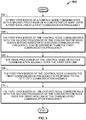
- FIG. 5 is a flowchart of another example method 500 that can be carried out by, for example, the engine control system 300 of FIG. 3 .
- a first processor of a control node communicates with a second processor of a concentrator node over a first data link at a first communication frequency.
- the first processor may send one or more messages to the second processor over a fiber optic data link at a communication frequency within the UV part of the frequency spectrum.
- the first processor of the control node communicates with the second processor of the concentrator node over a second data link at a second communication frequency that is different than the first communication frequency.
- the first processor may send one or more messages to the second processor over an Ethernet link at a communication frequency within the IR part of the frequency spectrum.
- the first processor of the control node detects a communication anomaly over the first data link.
- the first processor of the control node changes the first communication frequency in response to the detected communication anomaly. For example, in continuing the example from above, the first processor may change the fiber optic data link over the first communication link to a communication frequency 1 GPps.
- the first processor of the control node communicates with the second processor of the concentrator node over the first data link at the changed first communication frequency.
- control system and methods described herein may provide for data security and cyber security countermeasures within the control system.
- control system and methods allow for the use of more of the frequency spectrum for communications (e.g ., data exchange).
- control system and methods allow for the changing of communication frequencies and rates, as well as for data redundancy over multiple communication links that may be operating at differing communication frequencies and/or rates. Persons of ordinary skill in the art having the benefit of the disclosures herein would recognize these and other benefits as well.
Landscapes
- Engineering & Computer Science (AREA)
- Computer Security & Cryptography (AREA)
- Computer Networks & Wireless Communication (AREA)
- Signal Processing (AREA)
- Computer Hardware Design (AREA)
- General Engineering & Computer Science (AREA)
- Theoretical Computer Science (AREA)
- Software Systems (AREA)
- General Physics & Mathematics (AREA)
- Physics & Mathematics (AREA)
- Computing Systems (AREA)
- Radar, Positioning & Navigation (AREA)
- Remote Sensing (AREA)
- Selective Calling Equipment (AREA)
- Small-Scale Networks (AREA)
Claims (11)
- Steuersystem (202, 300) für ein Luftfahrzeugtriebwerk (102, 104), umfassend:eine erste Datenverbindung (314);eine zweite Datenverbindung (316);einen Steuerknoten (204, 302), der einen ersten Prozessor umfasst; undeinen Konzentratorknoten (206, 304), der einen zweiten Prozessor umfasst und über die erste Datenverbindung und über die zweite Datenverbindung an den Steuerknoten wirkgekoppelt ist;wobei der Steuerknoten mit dem Konzentratorknoten über die erste Datenverbindung bei einer ersten Kommunikationsfrequenz und einer ersten Kommunikationsrate kommuniziert; und die erste Kommunikationsfrequenz als Reaktion auf zumindest ein Ereignis ändert,wobei der Steuerknoten (204, 302) konfiguriert ist, um eine Frequenzänderungsangabe an den Konzentratorknoten (206, 304) zu senden, und wobei der Konzentratorknoten konfiguriert ist, um mit dem Steuerknoten bei der geänderten ersten Kommunikationsfrequenz als Reaktion auf das Empfangen der Frequenzänderungsangabe zu kommunizieren, undwobei der Steuerknoten (204, 302) konfiguriert ist, um die Frequenzänderungsangabe an den Konzentratorknoten über die zweite Datenverbindung zu senden.
- Steuersystem nach Anspruch 1, wobei der Steuerknoten (204, 302) konfiguriert ist, um die erste Kommunikationsfrequenz periodisch zu ändern, und wobei der Konzentratorknoten (206, 304) konfiguriert ist, um mit dem Steuerknoten bei jeder periodisch geänderten ersten Kommunikationsfrequenz als Reaktion auf das Empfangen der Frequenzänderungsangabe zu kommunizieren.
- Steuersystem nach Anspruch 1 oder 2, wobei der Steuerknoten (204, 302) konfiguriert ist, um mit dem Konzentratorknoten (206, 304) über die zweite Datenverbindung bei einer zweiten Kommunikationsrate zu kommunizieren, die sich von der ersten Kommunikationsrate unterscheidet.
- Steuersystem nach einem vorhergehenden Anspruch, ferner umfassend zumindest eine Komponente, die an den Konzentratorknoten (206, 304) über eine dritte Datenverbindung wirkgekoppelt ist, wobei der Konzentratorknoten konfiguriert ist, um mit der zumindest einen Komponente über die dritte Datenverbindung zu kommunizieren.
- Steuersystem nach Anspruch 4, wobei die zumindest eine Komponente zumindest eines von einem optischen Sensor (306), einem Aktuator (308) und einem intelligenten Sensor (310) umfasst.
- Steuersystem nach einem vorhergehenden Anspruch, wobei das Ändern der ersten Kommunikationsfrequenz als Reaktion auf das zumindest eine Ereignis Folgendes umfasst:Erfassen einer Cybersicherheitsbedrohung; undÄndern der ersten Kommunikationsfrequenz als Reaktion auf das Erfassen der Cybersicherheitsbedrohung.
- Steuersystem nach einem vorhergehenden Anspruch, wobei jede von der ersten Datenverbindung und der zweiten Datenverbindung eine Glasfaserverbindung sind, wobei der Steuerknoten (204, 302) ferner für Folgendes konfiguriert ist:Kommunizieren mit dem Konzentratorknoten (206, 304) über die erste Datenverbindung innerhalb eines ersten Frequenzbereichs, wobei die erste Kommunikationsfrequenz innerhalb des ersten Frequenzbereichs liegt; undKommunizieren mit dem Konzentratorknoten über die zweite Datenverbindung innerhalb eines zweiten Frequenzbereichs.
- Steuersystem nach einem vorhergehenden Anspruch, wobei die erste Datenverbindung (314) eine Glasfaserverbindung ist und die zweite Datenverbindung eine Ethernet-Verbindung ist.
- Steuersystem nach einem vorhergehenden Anspruch, wobei der Steuerknoten (204, 302) konfiguriert ist, um erste Daten über die erste Datenverbindung bei der ersten Kommunikationsrate zu übertragen und zweite Daten über die zweite Datenverbindung bei einer zweiten Kommunikationsrate zu übertragen, wobei die ersten Daten und die zweiten Daten redundant sind.
- Verfahren zum Steuern eines Luftfahrzeugtriebwerks, wobei das Verfahren Folgendes umfasst:Kommunizieren, durch einen ersten Prozessor eines Steuerknotens (204, 302), mit einem zweiten Prozessor eines Konzentratorknotens (206, 304) über eine erste Datenverbindung (314) bei einer ersten Kommunikationsfrequenz bei einer ersten Kommunikationsrate;Kommunizieren, durch den ersten Prozessor des Steuerknotens, mit dem zweiten Prozessor des Konzentratorknotens über eine zweite Datenverbindung (316) bei einer zweiten Kommunikationsrate, die sich von der ersten Kommunikationsrate unterscheidet;Erfassen, durch den ersten Prozessor des Steuerknotens, einer Kommunikationsanomalie über die erste Datenverbindung;Ändern, durch den ersten Prozessor des Steuerknotens, der ersten Kommunikationsfrequenz als Reaktion auf die erfasste Kommunikationsanomalie;Kommunizieren, durch den ersten Prozessor des Steuerknotens, mit dem zweiten Prozessor des Konzentratorknotens über die erste Datenverbindung bei der geänderten ersten Kommunikationsfrequenz;Übertragen, durch den Steuerknoten (204, 302), einer Frequenzänderungsangabe an den Konzentratorknoten (206, 304); undKommunizieren, durch den Konzentratorknoten mit dem Steuerknoten, bei der geänderten ersten Kommunikationsfrequenz als Reaktion auf das Empfangen der Frequenzänderungsangabe,wobei der Steuerknoten die Frequenzänderungsangabe an den Konzentratorknoten über die zweite Datenverbindung überträgt.
- Verfahren nach Anspruch 10, ferner umfassend:periodisches Ändern, durch den Steuerknoten (204, 302), der ersten Kommunikationsfrequenz;
undKommunizieren, durch den Konzentratorknoten mit dem Steuerknoten, bei jeder periodisch geänderten ersten Kommunikationsfrequenz als Reaktion auf das Empfangen der Frequenzänderungsangabe.
Applications Claiming Priority (1)
| Application Number | Priority Date | Filing Date | Title |
|---|---|---|---|
| US16/057,546 US10903871B2 (en) | 2018-08-07 | 2018-08-07 | Method of improved cyber security with frequency separation |
Publications (2)
| Publication Number | Publication Date |
|---|---|
| EP3609156A1 EP3609156A1 (de) | 2020-02-12 |
| EP3609156B1 true EP3609156B1 (de) | 2021-02-17 |
Family
ID=67437613
Family Applications (1)
| Application Number | Title | Priority Date | Filing Date |
|---|---|---|---|
| EP19184891.0A Active EP3609156B1 (de) | 2018-08-07 | 2019-07-08 | Verfahren zur verbesserten cyber-sicherheit mit frequenztrennung |
Country Status (3)
| Country | Link |
|---|---|
| US (1) | US10903871B2 (de) |
| EP (1) | EP3609156B1 (de) |
| CA (1) | CA3045619A1 (de) |
Family Cites Families (9)
| Publication number | Priority date | Publication date | Assignee | Title |
|---|---|---|---|---|
| US6782264B2 (en) * | 1999-01-08 | 2004-08-24 | Trueposition, Inc. | Monitoring of call information in a wireless location system |
| KR100410973B1 (ko) * | 2001-04-18 | 2003-12-18 | 엘지전자 주식회사 | 주문형 비디오 시스템에서 동영상의 스트리밍 방법 |
| GB0127254D0 (en) * | 2001-11-13 | 2002-01-02 | Lucas Industries Ltd | Aircraft flight surface control system |
| US7983835B2 (en) * | 2004-11-03 | 2011-07-19 | Lagassey Paul J | Modular intelligent transportation system |
| US7424040B2 (en) * | 2004-05-07 | 2008-09-09 | Ltas Holdings, Llc | Communication systems and methods for transmitting data in parallel over multiple channels |
| US9576404B2 (en) * | 2004-09-16 | 2017-02-21 | Harris Corporation | System and method of transmitting data from an aircraft |
| US9481473B2 (en) * | 2013-03-15 | 2016-11-01 | Rolls-Royce North American Technologies, Inc. | Distributed control system with smart actuators and sensors |
| US9756062B2 (en) | 2014-08-27 | 2017-09-05 | General Electric Company | Collaborative infrastructure supporting cyber-security analytics in industrial networks |
| US10623130B2 (en) | 2017-07-27 | 2020-04-14 | Rolls-Royce North American Technologes, Inc. | Determining a frequency for propulsor engine communication sessions |
-
2018
- 2018-08-07 US US16/057,546 patent/US10903871B2/en active Active
-
2019
- 2019-06-10 CA CA3045619A patent/CA3045619A1/en active Pending
- 2019-07-08 EP EP19184891.0A patent/EP3609156B1/de active Active
Non-Patent Citations (1)
| Title |
|---|
| None * |
Also Published As
| Publication number | Publication date |
|---|---|
| US20200052735A1 (en) | 2020-02-13 |
| EP3609156A1 (de) | 2020-02-12 |
| US10903871B2 (en) | 2021-01-26 |
| CA3045619A1 (en) | 2020-02-07 |
Similar Documents
| Publication | Publication Date | Title |
|---|---|---|
| US11456891B2 (en) | Apparatus and methods for authenticating cyber secure control system configurations using distributed ledgers | |
| EP3726481B1 (de) | Motorgateway mit motordatenspeicherung | |
| EP3182234B1 (de) | Steuerungsvorrichtung, integrierte industrieanlage und steuerungsverfahren dafür | |
| US11765091B2 (en) | Configurable network switch for industrial control systems including deterministic networks | |
| US10868817B2 (en) | Systems and methods for neutralizing masquerading attacks in vehicle control systems | |
| US10044564B2 (en) | Connecting node for a communications network | |
| EP3726323B1 (de) | Kommunikationsgateway für gasturbinenmotoren mit integrierten antennen | |
| EP3672196A1 (de) | Verfahren und verfahren zur blockchain-implementierung mit vorrichtungen dritter | |
| JP5411916B2 (ja) | 保護継電器とこれを備えるネットワークシステム | |
| CN109299029A (zh) | 用于更新至少一个规则的节点、车辆、集成电路和方法 | |
| EP2079196A1 (de) | Verfahren zum Schutz einer Netzwerkkonfigurationseinstellung anhand eines Spanning-Tree-Protokolls | |
| Olufowobi et al. | Controller area network intrusion prevention system leveraging fault recovery | |
| EP3798886B1 (de) | Vorrichtungen, systeme und verfahren zur sicheren initialisierung eines eingebetteten systems | |
| US11012453B2 (en) | Method for protecting a vehicle network against manipulated data transmission | |
| CN120378874B (zh) | 无人控制系统动态密钥信任链构建方法 | |
| Kwon et al. | Mitigation mechanism against in-vehicle network intrusion by reconfiguring ECU and disabling attack packet | |
| US11286906B2 (en) | Methods and apparatuses for data interchange with a wind turbine or a wind farm | |
| US10903871B2 (en) | Method of improved cyber security with frequency separation | |
| EP2375333A2 (de) | Avionikdatenvalidierungssystem | |
| EP3608823B1 (de) | Verfahren und prozess für cybersicherheit über software-bildgebung | |
| US10805005B2 (en) | Frequency spectrum system security | |
| US20210021618A1 (en) | Data communication control device, non-volatile memory, and vehicle control system | |
| US20190036638A1 (en) | Determining a frequency for propulsor engine communication sessions | |
| US20200412453A1 (en) | Optical Interface and Distributed Fiber Optic Communication Network for Controlling a Gas Turbine Engine and Method | |
| US20120291116A1 (en) | Network Security Device |
Legal Events
| Date | Code | Title | Description |
|---|---|---|---|
| PUAI | Public reference made under article 153(3) epc to a published international application that has entered the european phase |
Free format text: ORIGINAL CODE: 0009012 |
|
| STAA | Information on the status of an ep patent application or granted ep patent |
Free format text: STATUS: THE APPLICATION HAS BEEN PUBLISHED |
|
| AK | Designated contracting states |
Kind code of ref document: A1 Designated state(s): AL AT BE BG CH CY CZ DE DK EE ES FI FR GB GR HR HU IE IS IT LI LT LU LV MC MK MT NL NO PL PT RO RS SE SI SK SM TR |
|
| AX | Request for extension of the european patent |
Extension state: BA ME |
|
| STAA | Information on the status of an ep patent application or granted ep patent |
Free format text: STATUS: REQUEST FOR EXAMINATION WAS MADE |
|
| 17P | Request for examination filed |
Effective date: 20200811 |
|
| RBV | Designated contracting states (corrected) |
Designated state(s): AL AT BE BG CH CY CZ DE DK EE ES FI FR GB GR HR HU IE IS IT LI LT LU LV MC MK MT NL NO PL PT RO RS SE SI SK SM TR |
|
| GRAP | Despatch of communication of intention to grant a patent |
Free format text: ORIGINAL CODE: EPIDOSNIGR1 |
|
| STAA | Information on the status of an ep patent application or granted ep patent |
Free format text: STATUS: GRANT OF PATENT IS INTENDED |
|
| RIC1 | Information provided on ipc code assigned before grant |
Ipc: H04K 3/00 20060101ALI20200930BHEP Ipc: H04L 29/08 20060101ALI20200930BHEP Ipc: H04L 29/06 20060101AFI20200930BHEP Ipc: G06F 21/85 20130101ALI20200930BHEP Ipc: G06F 21/55 20130101ALI20200930BHEP Ipc: H04K 1/00 20060101ALI20200930BHEP |
|
| INTG | Intention to grant announced |
Effective date: 20201015 |
|
| GRAS | Grant fee paid |
Free format text: ORIGINAL CODE: EPIDOSNIGR3 |
|
| GRAA | (expected) grant |
Free format text: ORIGINAL CODE: 0009210 |
|
| STAA | Information on the status of an ep patent application or granted ep patent |
Free format text: STATUS: THE PATENT HAS BEEN GRANTED |
|
| AK | Designated contracting states |
Kind code of ref document: B1 Designated state(s): AL AT BE BG CH CY CZ DE DK EE ES FI FR GB GR HR HU IE IS IT LI LT LU LV MC MK MT NL NO PL PT RO RS SE SI SK SM TR |
|
| REG | Reference to a national code |
Ref country code: GB Ref legal event code: FG4D |
|
| REG | Reference to a national code |
Ref country code: CH Ref legal event code: EP |
|
| REG | Reference to a national code |
Ref country code: DE Ref legal event code: R096 Ref document number: 602019002557 Country of ref document: DE |
|
| REG | Reference to a national code |
Ref country code: AT Ref legal event code: REF Ref document number: 1363007 Country of ref document: AT Kind code of ref document: T Effective date: 20210315 |
|
| REG | Reference to a national code |
Ref country code: IE Ref legal event code: FG4D |
|
| REG | Reference to a national code |
Ref country code: LT Ref legal event code: MG9D |
|
| REG | Reference to a national code |
Ref country code: NL Ref legal event code: MP Effective date: 20210217 |
|
| PG25 | Lapsed in a contracting state [announced via postgrant information from national office to epo] |
Ref country code: BG Free format text: LAPSE BECAUSE OF FAILURE TO SUBMIT A TRANSLATION OF THE DESCRIPTION OR TO PAY THE FEE WITHIN THE PRESCRIBED TIME-LIMIT Effective date: 20210517 Ref country code: HR Free format text: LAPSE BECAUSE OF FAILURE TO SUBMIT A TRANSLATION OF THE DESCRIPTION OR TO PAY THE FEE WITHIN THE PRESCRIBED TIME-LIMIT Effective date: 20210217 Ref country code: FI Free format text: LAPSE BECAUSE OF FAILURE TO SUBMIT A TRANSLATION OF THE DESCRIPTION OR TO PAY THE FEE WITHIN THE PRESCRIBED TIME-LIMIT Effective date: 20210217 Ref country code: GR Free format text: LAPSE BECAUSE OF FAILURE TO SUBMIT A TRANSLATION OF THE DESCRIPTION OR TO PAY THE FEE WITHIN THE PRESCRIBED TIME-LIMIT Effective date: 20210518 Ref country code: LT Free format text: LAPSE BECAUSE OF FAILURE TO SUBMIT A TRANSLATION OF THE DESCRIPTION OR TO PAY THE FEE WITHIN THE PRESCRIBED TIME-LIMIT Effective date: 20210217 Ref country code: PT Free format text: LAPSE BECAUSE OF FAILURE TO SUBMIT A TRANSLATION OF THE DESCRIPTION OR TO PAY THE FEE WITHIN THE PRESCRIBED TIME-LIMIT Effective date: 20210617 Ref country code: NO Free format text: LAPSE BECAUSE OF FAILURE TO SUBMIT A TRANSLATION OF THE DESCRIPTION OR TO PAY THE FEE WITHIN THE PRESCRIBED TIME-LIMIT Effective date: 20210517 |
|
| REG | Reference to a national code |
Ref country code: AT Ref legal event code: MK05 Ref document number: 1363007 Country of ref document: AT Kind code of ref document: T Effective date: 20210217 |
|
| PG25 | Lapsed in a contracting state [announced via postgrant information from national office to epo] |
Ref country code: RS Free format text: LAPSE BECAUSE OF FAILURE TO SUBMIT A TRANSLATION OF THE DESCRIPTION OR TO PAY THE FEE WITHIN THE PRESCRIBED TIME-LIMIT Effective date: 20210217 Ref country code: SE Free format text: LAPSE BECAUSE OF FAILURE TO SUBMIT A TRANSLATION OF THE DESCRIPTION OR TO PAY THE FEE WITHIN THE PRESCRIBED TIME-LIMIT Effective date: 20210217 Ref country code: LV Free format text: LAPSE BECAUSE OF FAILURE TO SUBMIT A TRANSLATION OF THE DESCRIPTION OR TO PAY THE FEE WITHIN THE PRESCRIBED TIME-LIMIT Effective date: 20210217 Ref country code: NL Free format text: LAPSE BECAUSE OF FAILURE TO SUBMIT A TRANSLATION OF THE DESCRIPTION OR TO PAY THE FEE WITHIN THE PRESCRIBED TIME-LIMIT Effective date: 20210217 Ref country code: PL Free format text: LAPSE BECAUSE OF FAILURE TO SUBMIT A TRANSLATION OF THE DESCRIPTION OR TO PAY THE FEE WITHIN THE PRESCRIBED TIME-LIMIT Effective date: 20210217 |
|
| PG25 | Lapsed in a contracting state [announced via postgrant information from national office to epo] |
Ref country code: IS Free format text: LAPSE BECAUSE OF FAILURE TO SUBMIT A TRANSLATION OF THE DESCRIPTION OR TO PAY THE FEE WITHIN THE PRESCRIBED TIME-LIMIT Effective date: 20210617 |
|
| PG25 | Lapsed in a contracting state [announced via postgrant information from national office to epo] |
Ref country code: CZ Free format text: LAPSE BECAUSE OF FAILURE TO SUBMIT A TRANSLATION OF THE DESCRIPTION OR TO PAY THE FEE WITHIN THE PRESCRIBED TIME-LIMIT Effective date: 20210217 Ref country code: EE Free format text: LAPSE BECAUSE OF FAILURE TO SUBMIT A TRANSLATION OF THE DESCRIPTION OR TO PAY THE FEE WITHIN THE PRESCRIBED TIME-LIMIT Effective date: 20210217 Ref country code: SM Free format text: LAPSE BECAUSE OF FAILURE TO SUBMIT A TRANSLATION OF THE DESCRIPTION OR TO PAY THE FEE WITHIN THE PRESCRIBED TIME-LIMIT Effective date: 20210217 Ref country code: AT Free format text: LAPSE BECAUSE OF FAILURE TO SUBMIT A TRANSLATION OF THE DESCRIPTION OR TO PAY THE FEE WITHIN THE PRESCRIBED TIME-LIMIT Effective date: 20210217 |
|
| REG | Reference to a national code |
Ref country code: DE Ref legal event code: R097 Ref document number: 602019002557 Country of ref document: DE |
|
| REG | Reference to a national code |
Ref country code: DE Ref legal event code: R079 Ref document number: 602019002557 Country of ref document: DE Free format text: PREVIOUS MAIN CLASS: H04L0029060000 Ipc: H04L0065000000 |
|
| PG25 | Lapsed in a contracting state [announced via postgrant information from national office to epo] |
Ref country code: DK Free format text: LAPSE BECAUSE OF FAILURE TO SUBMIT A TRANSLATION OF THE DESCRIPTION OR TO PAY THE FEE WITHIN THE PRESCRIBED TIME-LIMIT Effective date: 20210217 Ref country code: SK Free format text: LAPSE BECAUSE OF FAILURE TO SUBMIT A TRANSLATION OF THE DESCRIPTION OR TO PAY THE FEE WITHIN THE PRESCRIBED TIME-LIMIT Effective date: 20210217 Ref country code: RO Free format text: LAPSE BECAUSE OF FAILURE TO SUBMIT A TRANSLATION OF THE DESCRIPTION OR TO PAY THE FEE WITHIN THE PRESCRIBED TIME-LIMIT Effective date: 20210217 |
|
| PLBE | No opposition filed within time limit |
Free format text: ORIGINAL CODE: 0009261 |
|
| STAA | Information on the status of an ep patent application or granted ep patent |
Free format text: STATUS: NO OPPOSITION FILED WITHIN TIME LIMIT |
|
| 26N | No opposition filed |
Effective date: 20211118 |
|
| PG25 | Lapsed in a contracting state [announced via postgrant information from national office to epo] |
Ref country code: ES Free format text: LAPSE BECAUSE OF FAILURE TO SUBMIT A TRANSLATION OF THE DESCRIPTION OR TO PAY THE FEE WITHIN THE PRESCRIBED TIME-LIMIT Effective date: 20210217 Ref country code: AL Free format text: LAPSE BECAUSE OF FAILURE TO SUBMIT A TRANSLATION OF THE DESCRIPTION OR TO PAY THE FEE WITHIN THE PRESCRIBED TIME-LIMIT Effective date: 20210217 |
|
| REG | Reference to a national code |
Ref country code: DE Ref legal event code: R119 Ref document number: 602019002557 Country of ref document: DE |
|
| PG25 | Lapsed in a contracting state [announced via postgrant information from national office to epo] |
Ref country code: SI Free format text: LAPSE BECAUSE OF FAILURE TO SUBMIT A TRANSLATION OF THE DESCRIPTION OR TO PAY THE FEE WITHIN THE PRESCRIBED TIME-LIMIT Effective date: 20210217 |
|
| PG25 | Lapsed in a contracting state [announced via postgrant information from national office to epo] |
Ref country code: MC Free format text: LAPSE BECAUSE OF FAILURE TO SUBMIT A TRANSLATION OF THE DESCRIPTION OR TO PAY THE FEE WITHIN THE PRESCRIBED TIME-LIMIT Effective date: 20210217 |
|
| REG | Reference to a national code |
Ref country code: BE Ref legal event code: MM Effective date: 20210731 |
|
| PG25 | Lapsed in a contracting state [announced via postgrant information from national office to epo] |
Ref country code: IT Free format text: LAPSE BECAUSE OF FAILURE TO SUBMIT A TRANSLATION OF THE DESCRIPTION OR TO PAY THE FEE WITHIN THE PRESCRIBED TIME-LIMIT Effective date: 20210217 Ref country code: DE Free format text: LAPSE BECAUSE OF NON-PAYMENT OF DUE FEES Effective date: 20220201 |
|
| PG25 | Lapsed in a contracting state [announced via postgrant information from national office to epo] |
Ref country code: IS Free format text: LAPSE BECAUSE OF FAILURE TO SUBMIT A TRANSLATION OF THE DESCRIPTION OR TO PAY THE FEE WITHIN THE PRESCRIBED TIME-LIMIT Effective date: 20210617 Ref country code: LU Free format text: LAPSE BECAUSE OF NON-PAYMENT OF DUE FEES Effective date: 20210708 |
|
| PG25 | Lapsed in a contracting state [announced via postgrant information from national office to epo] |
Ref country code: IE Free format text: LAPSE BECAUSE OF NON-PAYMENT OF DUE FEES Effective date: 20210708 Ref country code: BE Free format text: LAPSE BECAUSE OF NON-PAYMENT OF DUE FEES Effective date: 20210731 |
|
| REG | Reference to a national code |
Ref country code: CH Ref legal event code: PL |
|
| PG25 | Lapsed in a contracting state [announced via postgrant information from national office to epo] |
Ref country code: LI Free format text: LAPSE BECAUSE OF NON-PAYMENT OF DUE FEES Effective date: 20220731 Ref country code: CH Free format text: LAPSE BECAUSE OF NON-PAYMENT OF DUE FEES Effective date: 20220731 |
|
| PG25 | Lapsed in a contracting state [announced via postgrant information from national office to epo] |
Ref country code: CY Free format text: LAPSE BECAUSE OF FAILURE TO SUBMIT A TRANSLATION OF THE DESCRIPTION OR TO PAY THE FEE WITHIN THE PRESCRIBED TIME-LIMIT Effective date: 20210217 |
|
| P01 | Opt-out of the competence of the unified patent court (upc) registered |
Effective date: 20230528 |
|
| PG25 | Lapsed in a contracting state [announced via postgrant information from national office to epo] |
Ref country code: HU Free format text: LAPSE BECAUSE OF FAILURE TO SUBMIT A TRANSLATION OF THE DESCRIPTION OR TO PAY THE FEE WITHIN THE PRESCRIBED TIME-LIMIT; INVALID AB INITIO Effective date: 20190708 |
|
| GBPC | Gb: european patent ceased through non-payment of renewal fee |
Effective date: 20230708 |
|
| PG25 | Lapsed in a contracting state [announced via postgrant information from national office to epo] |
Ref country code: MK Free format text: LAPSE BECAUSE OF FAILURE TO SUBMIT A TRANSLATION OF THE DESCRIPTION OR TO PAY THE FEE WITHIN THE PRESCRIBED TIME-LIMIT Effective date: 20210217 Ref country code: GB Free format text: LAPSE BECAUSE OF NON-PAYMENT OF DUE FEES Effective date: 20230708 |
|
| PG25 | Lapsed in a contracting state [announced via postgrant information from national office to epo] |
Ref country code: MT Free format text: LAPSE BECAUSE OF FAILURE TO SUBMIT A TRANSLATION OF THE DESCRIPTION OR TO PAY THE FEE WITHIN THE PRESCRIBED TIME-LIMIT Effective date: 20210217 |
|
| PGFP | Annual fee paid to national office [announced via postgrant information from national office to epo] |
Ref country code: FR Payment date: 20250725 Year of fee payment: 7 |
|
| PG25 | Lapsed in a contracting state [announced via postgrant information from national office to epo] |
Ref country code: TR Free format text: LAPSE BECAUSE OF FAILURE TO SUBMIT A TRANSLATION OF THE DESCRIPTION OR TO PAY THE FEE WITHIN THE PRESCRIBED TIME-LIMIT Effective date: 20210217 |