EP3609029A1 - Clamp for a wire of an overhead line and method for tightening a wire of an overhead line - Google Patents
Clamp for a wire of an overhead line and method for tightening a wire of an overhead line Download PDFInfo
- Publication number
- EP3609029A1 EP3609029A1 EP18306083.9A EP18306083A EP3609029A1 EP 3609029 A1 EP3609029 A1 EP 3609029A1 EP 18306083 A EP18306083 A EP 18306083A EP 3609029 A1 EP3609029 A1 EP 3609029A1
- Authority
- EP
- European Patent Office
- Prior art keywords
- clamp
- wire
- groove
- tapered region
- wedge elements
- Prior art date
- Legal status (The legal status is an assumption and is not a legal conclusion. Google has not performed a legal analysis and makes no representation as to the accuracy of the status listed.)
- Granted
Links
Images




Classifications
-
- H—ELECTRICITY
- H02—GENERATION; CONVERSION OR DISTRIBUTION OF ELECTRIC POWER
- H02G—INSTALLATION OF ELECTRIC CABLES OR LINES, OR OF COMBINED OPTICAL AND ELECTRIC CABLES OR LINES
- H02G7/00—Overhead installations of electric lines or cables
- H02G7/05—Suspension arrangements or devices for electric cables or lines
- H02G7/053—Suspension clamps and clips for electric overhead lines not suspended to a supporting wire
-
- B—PERFORMING OPERATIONS; TRANSPORTING
- B60—VEHICLES IN GENERAL
- B60M—POWER SUPPLY LINES, AND DEVICES ALONG RAILS, FOR ELECTRICALLY- PROPELLED VEHICLES
- B60M1/00—Power supply lines for contact with collector on vehicle
- B60M1/12—Trolley lines; Accessories therefor
- B60M1/20—Arrangements for supporting or suspending trolley wires, e.g. from buildings
- B60M1/24—Clamps; Splicers; Anchor tips
-
- F—MECHANICAL ENGINEERING; LIGHTING; HEATING; WEAPONS; BLASTING
- F16—ENGINEERING ELEMENTS AND UNITS; GENERAL MEASURES FOR PRODUCING AND MAINTAINING EFFECTIVE FUNCTIONING OF MACHINES OR INSTALLATIONS; THERMAL INSULATION IN GENERAL
- F16L—PIPES; JOINTS OR FITTINGS FOR PIPES; SUPPORTS FOR PIPES, CABLES OR PROTECTIVE TUBING; MEANS FOR THERMAL INSULATION IN GENERAL
- F16L3/00—Supports for pipes, cables or protective tubing, e.g. hangers, holders, clamps, cleats, clips, brackets
- F16L3/08—Supports for pipes, cables or protective tubing, e.g. hangers, holders, clamps, cleats, clips, brackets substantially surrounding the pipe, cable or protective tubing
- F16L3/10—Supports for pipes, cables or protective tubing, e.g. hangers, holders, clamps, cleats, clips, brackets substantially surrounding the pipe, cable or protective tubing divided, i.e. with two members engaging the pipe, cable or protective tubing
- F16L3/1075—Supports for pipes, cables or protective tubing, e.g. hangers, holders, clamps, cleats, clips, brackets substantially surrounding the pipe, cable or protective tubing divided, i.e. with two members engaging the pipe, cable or protective tubing with two members, the two members being joined with a hinge on one side and fastened together on the other side
Definitions
- the present invention relates to a clamp for a wire, notably a messenger wire of an overhead line and to a method for tightening a messenger wire of an overhead line.
- An overhead line or overhead wire is commonly used to transmit electrical energy to trams or trains.
- the main component of such overhead line is a support and electric power supply cable, or messenger wire, which is fixed through clamps to a plurality of cantilevers of a metallic support structure of the overhead line.
- the messenger wire is in turn connected, through commonly known droppers, to a contact wire, on which a pantograph is pressed, in a manner known per se, to collect current from the overhead line for supplying the trains or trams.
- clamps with one or two screws are widely used to lock the messenger wire which is hosted in a groove of the clamp itself, but the process of tightening the screws is long and requires around 50% of the installation time.
- the operator firstly go up the cage and fix the messenger wire in a groove clamp, this operation being replicated for all the cantilevers of the overhead line. After that, the operator put the messenger wire under tension, and finally he comes back to every cantilever to tighten the screws.
- the time necessary to tight all the screws of the clamps amounts to about 40% of the total time necessary for installing the messenger wire on each cantilever of the overhead line, which usually amounts to 2-3 minutes.
- a clamp for a messenger wire of an overhead line having the characteristics defined in claim 1 and by a method for tightening a messenger wire of an overhead line having the characteristics defined in claim 11.
- Figure 1 shows a perspective top view of a clamp for a wire, notably a messenger wire 1 according to the present invention. It comprises a main body 2 having a groove 4 extending longitudinally along a longitudinal axis X for hosting a messenger wire 6. A first and a second wedge elements 8a, 8b are arranged for tightening the messenger wire 6 being pushed in opposite directions along said longitudinal axis X by respective first and second springs 10a, 10b, as detailed here below.
- the wedge elements 8a, 8b are placed in a respective first and second tapered regions 12a, 12b of the main body 2, said first and second tapered regions 12a, 12b being located in the groove 4, towards respective ends of the groove 4.
- the springs 10a, 10b are placed in respective holes on opposite sides of the groove 4, facing each other, said holes being located in a central portion of the groove 4.
- the wedge elements 8a, 8b have a tapered shape complementary to the shape of a part of the corresponding tapered regions 12a, 12b in which they are received.
- first wedge element 8a When the first wedge element 8a is pushed in the first tapered region 12a, in a first direction A, by the associated first spring 10a, it tightens the messenger wire 6 because it is blocked between the messenger wire 6 itself and a wall of the first tapered region 12a.
- second wedge element 8b when the second wedge element 8b is pushed in the second tapered region 12b, in a second direction B opposite to the first direction A, by the associated second spring 10b, it tightens the messenger wire 6 because it is blocked between the messenger wire 6 itself and a wall of the second tapered region 12b.
- each wedge element 8a, 8b increases the tightening force on the messenger wire 6.
- Each wedge elements 8a, 8b comprises a bottom threaded part 14 for increasing the grip to the messenger wire 6.
- each tapered region 12a, 12b comprises, along the longitudinal axis X of the groove 4, a proximal end 22 oriented towards a central portion of the groove 4 and a distal end 24 oriented away from said central portion of the groove 4.
- Each tapered region 12a, 12b further comprises a compression portion placed between a maintaining part 26 of the corresponding wedge element 8a, 8b and its distal end, the width of said compression portion measured perpendicularly to the longitudinal axis X of the groove 4 being lower than a maximal width of the maintaining part.
- the width of the compression portion measured perpendicularly to the longitudinal axis X is lower than a predetermined minimal width of the maintaining part.
- said predetermined minimal width is a minimal width of the wedge element 8a, 8b.
- the wedge elements 8a, 8b have a length, measured along the longitudinal axis X, lower than a length of the corresponding tapered region 12a, 12b measured along said longitudinal axis X.
- Figure 2 shows a further perspective view of the clamp 1 wherein the messenger wire 6 is fully inserted into the clamp 1.
- Figure 3 shows a further top view of the clamp 1 further including a cover 16 of the clamp 1 arranged for covering the main body 2.
- Figure 4 shows a perspective posterior view of the clamp 1 further including a safety plug 18, located in the main body 2, arranged to keep the springs 10a, 10b in a compressed position wherein they do not push the respective wedge elements 8a, 8b into the tapered regions 12a, 12b.
- a safety plug 18 located in the main body 2, arranged to keep the springs 10a, 10b in a compressed position wherein they do not push the respective wedge elements 8a, 8b into the tapered regions 12a, 12b.
- the operator need to remove such safety plug 18, as detailed herein below.
- the safety plug 18 has a U shape.
- Figure 5 shows an enlarged posterior view of the clamp 1.
- the holes 20 permit an easy access to the area of the springs 10a, 10b in order to compress them and then to move back the wedge elements 8a, 8b to free the messenger wire 6.
- Figure 6 shows a block diagram of the steps of a method for tightening a messenger wire of an overhead line according to the present invention.
- a clamp 1 as above disclosed is provided.
- the springs 10a, 10b are in a compressed state due to the presence of the safety plug 18.
- the messenger wire 6 is inserted, in a step 102, into the groove 4.
- each spring 10a, 10b can push, in a step 106, the respective wedge element 8a, 8b in the respective tapered region 12a, 12b.
- each wedge element 8a, 8b tighten the messenger wire 6 as above disclosed.
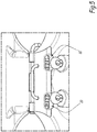
- Figure 7 shows a top view of a portion of the clamp 1 wherein it is shown how the springs 10a, 10b produce respective compression forces, indicated by arrows C, on the associated wedges 8a, 8b.
- each wedge elements 8a, 8b is in the respective tapered regions 12a, 12b makes the tightening forces on the messenger wire 6 resulting from the springs 12a, 12b exercising not along the longitudinal axis X of the clamp 1 but perpendicularly to such longitudinal axis X, so the more the messenger wire 6 and the spring 10a, 10b pulls/pushes the wedge element 8a, 8b, the more the wedge element 8a, 8b tightens the messenger wire 6, because the wedge 8a, 8b can only follow the direction of the tapered region 12a, 12b.
- the walls of the tapered regions 12a, 12b and the ones of the wedge elements 8a, 8b are configured so that when the force exerted by the walls on the wedge elements 8a, 8b increases, due to the movement of the wedge elements 8a, 8b in the tapered regions 12a, 12b, which comes from the pulling effort of the messenger wire 6 and the pushing effort of the springs 10a, 10b exercised on the wedge elements 8a, 8b, the width of the wedge elements 8a, 8b reduces, thus the tightening force on the messenger wire 6 increases.
- Figure 8 shows a top view of a portion of the clamp 1 wherein the tightening forces are indicated by arrows D.
- the main advantages of the clamp 1 of the present invention are:
Landscapes
- Engineering & Computer Science (AREA)
- General Engineering & Computer Science (AREA)
- Mechanical Engineering (AREA)
- Suspension Of Electric Lines Or Cables (AREA)
- Clamps And Clips (AREA)
Abstract
Description
- The present invention relates to a clamp for a wire, notably a messenger wire of an overhead line and to a method for tightening a messenger wire of an overhead line.
- An overhead line or overhead wire is commonly used to transmit electrical energy to trams or trains. The main component of such overhead line is a support and electric power supply cable, or messenger wire, which is fixed through clamps to a plurality of cantilevers of a metallic support structure of the overhead line. The messenger wire is in turn connected, through commonly known droppers, to a contact wire, on which a pantograph is pressed, in a manner known per se, to collect current from the overhead line for supplying the trains or trams.
- Nowadays, several different types of clamps are available on the market. Clamps with one or two screws are widely used to lock the messenger wire which is hosted in a groove of the clamp itself, but the process of tightening the screws is long and requires around 50% of the installation time.
- Other different types of clamps are known, respectively:
- clamps which do not require screws, but which comprise more than one component;
- clamps obtained by single metallic sheet, cut and bent, but including a screw to lock the wire into the clamp;
- clamps similar to a clothespin, with an elastic element, and comprising more than one component.
- The main disadvantage of all these clamps is that they either require multiple components or require screws, thus facilitating the possibility of losing components during the transportation to the site where the messenger wire has to be assembled, or making the installation phases complex.
- For example, when using clamps with screws for locking the messenger wire in the groove, the operator need to go outside the cage used during the installation steps to put the wire inside the clamp, and then close it.
- In particular, the operator firstly go up the cage and fix the messenger wire in a groove clamp, this operation being replicated for all the cantilevers of the overhead line. After that, the operator put the messenger wire under tension, and finally he comes back to every cantilever to tighten the screws.
- The steps that the operator has therefore to perform are the followings:
- installing the cantilevers on the structure of the overhead line;
- inserting the messenger wire in all the clamps of all the cantilevers;
- tensioning the messenger wire;
- returning to each clamp and screwing it.
- Sometimes it happens that the operator forgets some screws during the tightening phase, and he has to recover them from a storage which is usually located outside the cage, thus loosing time.
- In any case, the time necessary to tight all the screws of the clamps amounts to about 40% of the total time necessary for installing the messenger wire on each cantilever of the overhead line, which usually amounts to 2-3 minutes.
- There is therefore the need to have a clamp for a messenger wire of an overhead line which does not require screws for its assembly and which is easy to tighten, thus overcoming the limitations of the prior art solutions.
- These and other objects are achieved by a clamp for a messenger wire of an overhead line having the characteristics defined in
claim 1, and by a method for tightening a messenger wire of an overhead line having the characteristics defined in claim 11. - Preferred embodiments of the invention are the subject matter of the dependent claims, whose content is to be understood as forming an integral part of the present description.
- Further characteristics and advantages of the present invention will become apparent from the following description, provided merely by way of non-limiting example, with reference to the enclosed drawings, in which:
-
Figure 1 shows a perspective top view of a clamp for amessenger wire 1 according to the present invention; -
Figure 2 shows a further perspective view of the clamp offigure 1 ; -
Figure 3 shows a further top view of theclamp 1 further including a cover; -
Figure 4 shows a perspective posterior view of the clamp including a safety plug; -
Figure 5 is an enlarged posterior view of the clamp; -
Figure 6 shows a block diagram of the steps of a method for tightening a messenger wire according to the present invention; -
Figure 7 shows a top view of a portion of the clamp showing the compression forces; and -
Figure 8 shows a top view of a portion of the clamp showing the tightening forces. -
Figure 1 shows a perspective top view of a clamp for a wire, notably amessenger wire 1 according to the present invention. It comprises amain body 2 having a groove 4 extending longitudinally along a longitudinal axis X for hosting amessenger wire 6. A first and asecond wedge elements messenger wire 6 being pushed in opposite directions along said longitudinal axis X by respective first andsecond springs - In
figure 1 themessenger wire 6 is only partially inserted into theclamp 1, thus allowing a complete view of thewedge elements - The
wedge elements tapered regions main body 2, said first and secondtapered regions springs - Advantageously, the
wedge elements tapered regions - When the
first wedge element 8a is pushed in the firsttapered region 12a, in a first direction A, by the associatedfirst spring 10a, it tightens themessenger wire 6 because it is blocked between themessenger wire 6 itself and a wall of the firsttapered region 12a. Similarly, when thesecond wedge element 8b is pushed in the secondtapered region 12b, in a second direction B opposite to the first direction A, by the associatedsecond spring 10b, it tightens themessenger wire 6 because it is blocked between themessenger wire 6 itself and a wall of the secondtapered region 12b. - If the
messenger wire 6 further pulls eachwedge element messenger wire 6 itself, eachwedge element messenger wire 6. - Therefore, thanks to the presence of the
wedge elements messenger wire 6 pulls eachwedge element wedge element messenger wire 6. - Each
wedge elements part 14 for increasing the grip to themessenger wire 6. - Advantageously, each
tapered region proximal end 22 oriented towards a central portion of the groove 4 and adistal end 24 oriented away from said central portion of the groove 4. Eachtapered region part 26 of thecorresponding wedge element - Advantageously, the width of the compression portion measured perpendicularly to the longitudinal axis X is lower than a predetermined minimal width of the maintaining part. Preferably, said predetermined minimal width is a minimal width of the
wedge element - Advantageously, the
wedge elements tapered region -
Figure 2 shows a further perspective view of theclamp 1 wherein themessenger wire 6 is fully inserted into theclamp 1. -
Figure 3 shows a further top view of theclamp 1 further including acover 16 of theclamp 1 arranged for covering themain body 2. -
Figure 4 shows a perspective posterior view of theclamp 1 further including asafety plug 18, located in themain body 2, arranged to keep thesprings respective wedge elements tapered regions springs wedge elements messenger wire 6, the operator need to removesuch safety plug 18, as detailed herein below. - Preferably, the
safety plug 18 has a U shape. - If the operator, after having tightened the
messenger wire 6, needs to free it, he has to insert a special clamp, i.e. a specific tool, into twoholes 20.Figure 5 shows an enlarged posterior view of theclamp 1. Theholes 20 permit an easy access to the area of thesprings wedge elements messenger wire 6. -
Figure 6 shows a block diagram of the steps of a method for tightening a messenger wire of an overhead line according to the present invention. - In a first step 100 a
clamp 1 as above disclosed is provided. Thesprings safety plug 18. - After the compression, the
messenger wire 6 is inserted, in astep 102, into the groove 4. - At this point, in a
step 104, thesafety plug 18 is removed from its seat so that eachspring step 106, therespective wedge element tapered region - Finally, in a
step 108, eachwedge element messenger wire 6 as above disclosed. -
Figure 7 shows a top view of a portion of theclamp 1 wherein it is shown how thesprings wedges - The fact that each
wedge elements tapered regions messenger wire 6 resulting from thesprings clamp 1 but perpendicularly to such longitudinal axis X, so the more themessenger wire 6 and thespring wedge element wedge element messenger wire 6, because thewedge region - Advantageously, the walls of the
tapered regions wedge elements wedge elements wedge elements tapered regions messenger wire 6 and the pushing effort of thesprings wedge elements wedge elements messenger wire 6 increases. -
Figure 8 shows a top view of a portion of theclamp 1 wherein the tightening forces are indicated by arrows D. - The main advantages of the
clamp 1 of the present invention are: - reduced time of set up during tightening the
messenger wire 6; - increase safety for the operator during the clamp installation phase;
- plug and play system due to the presence of the
safety plug 18; - no impact on the infrastructure of the overhead line;
- Thanks to the
clamp 1 of the present invention, the operator has to perform the following operations: - installing the cantilevers on the support structure of the overhead line;
- insert the
messenger wire 6 in all the clamps of all the cantilevers; - tensioning the
messenger wire 6; - returning to each clamp and removing the
safety plug 18. - This last operation is easier and speeder than the corresponding one of the prior art solution, i.e. screwing each clamps.
- Clearly, the principle of the invention remaining the same, the embodiments and the details of production can be varied considerably from what has been described and illustrated purely by way of non-limiting example, without departing from the scope of protection of the present invention as defined by the attached claims.
Claims (11)
- A clamp (1) for a wire (6) of an overhead line comprising a main body (2) having a groove (4) for hosting the wire (6), a first and a second tapered region (12a, 12b) located in respective ends of the groove (4), a first and a second spring (10a, 10b) arranged for pushing respective wedge elements (8a, 8b) into the tapered regions (12a, 12b) in opposite directions (A, B), said wedge elements (8a, 8b) being arranged for tightening the wire (6) by blocking between the wire (6) itself and a wall of the respective first and second tapered region (12a, 12b).
- The clamp (1) according to claim 1, wherein each wedge element (8a, 8b) comprises a bottom threaded part (14) for increasing the grip to the wire (6).
- The clamp (1) according to claim 1 or 2, further including a cover (16) arranged for covering the main body (2).
- The clamp (1) according to any of the preceding claims, further including a removable safety plug (18) located in a posterior side of the main body (2) and arranged to keep the springs (10a, 10b) in an compressed position wherein they do not push the respective wedge elements (8a, 8b) into the tapered regions (12a, 12b).
- The clamp (1) according to any of the preceding claims, further comprising holes (20) arranged to permit an access at an area comprising the springs (10a, 10b) via a predetermined tool in order to compress the springs (10a , 10b) and to free the wire (6).
- The clamp (1) according to any of the preceding claims, wherein the wedge elements (8a, 8b) have a tapered shape complementary to the shape of a part of the corresponding tapered region (12a, 12b) in which they are received.
- The clamp (1) according to any of the preceding claims, wherein each tapered region (12a, 12b) comprises, along a longitudinal axis (X) of the groove (4), a proximal end (22) oriented towards a central portion of the groove (4) and a distal end (24) oriented away from said central portion of the groove (4), and wherein each tapered region (12a, 12b) comprises a compression portion placed between a maintaining part (26) of the corresponding wedge element (8a, 8b) and its distal end (24), the width of said compression portion measured perpendicularly to the longitudinal axis (X) of the groove (4) being lower than a maximal width of the maintaining part (26).
- The clamp (1) according to claim 7, wherein the width of the compression portion measured perpendicularly to the longitudinal axis (X) of the groove (4) is lower than a predetermined minimal width of the maintaining part (26).
- The clamp (1) according to claim 8, wherein said predetermined minimal width is a minimal width of the wedge element (8a, 8b).
- The clamp (1) according to any of the claims 7 to 9, wherein the wedge elements (8a, 8b) have a length, measured along the longitudinal axis (X) of the groove (4), lower than a length of the corresponding tapered region (12a, 12b) measured according to said longitudinal axis (X).
- A method for tightening a wire (6) of an overhead line comprising the steps of:- providing (100) a clamp (1) according to claim 4;- inserting (102) the wire (6) into the groove (4);- removing (104) the safety plug (18) from its seat;- pushing (106) through the springs (10a, 10b) the wedge elements (8a, 8b) in the respective tapered region (12a, 12b) thus tightening (108) the wire (6).
Priority Applications (4)
| Application Number | Priority Date | Filing Date | Title |
|---|---|---|---|
| EP18306083.9A EP3609029B1 (en) | 2018-08-06 | 2018-08-06 | Clamp for a wire of an overhead line and method for tightening a wire of an overhead line |
| ES18306083T ES2852773T3 (en) | 2018-08-06 | 2018-08-06 | Clamp for an overhead line cable and method of tightening an overhead line cable |
| CA3051260A CA3051260A1 (en) | 2018-08-06 | 2019-08-05 | Clamp for a wire of an overhead line and method for tightening a wire of an overhead line |
| US16/531,479 US11063416B2 (en) | 2018-08-06 | 2019-08-05 | Clamp for a wire of an overhead line and method for tightening a wire of an overhead line |
Applications Claiming Priority (1)
| Application Number | Priority Date | Filing Date | Title |
|---|---|---|---|
| EP18306083.9A EP3609029B1 (en) | 2018-08-06 | 2018-08-06 | Clamp for a wire of an overhead line and method for tightening a wire of an overhead line |
Publications (2)
| Publication Number | Publication Date |
|---|---|
| EP3609029A1 true EP3609029A1 (en) | 2020-02-12 |
| EP3609029B1 EP3609029B1 (en) | 2020-11-25 |
Family
ID=63259475
Family Applications (1)
| Application Number | Title | Priority Date | Filing Date |
|---|---|---|---|
| EP18306083.9A Active EP3609029B1 (en) | 2018-08-06 | 2018-08-06 | Clamp for a wire of an overhead line and method for tightening a wire of an overhead line |
Country Status (4)
| Country | Link |
|---|---|
| US (1) | US11063416B2 (en) |
| EP (1) | EP3609029B1 (en) |
| CA (1) | CA3051260A1 (en) |
| ES (1) | ES2852773T3 (en) |
Families Citing this family (2)
| Publication number | Priority date | Publication date | Assignee | Title |
|---|---|---|---|---|
| CN113507038B (en) * | 2021-07-15 | 2022-09-09 | 深圳市中科光芯半导体科技有限公司 | Semiconductor laser |
| JP7749503B2 (en) * | 2022-03-29 | 2025-10-06 | 三和テッキ株式会社 | Suspension wire protection cover |
Citations (6)
| Publication number | Priority date | Publication date | Assignee | Title |
|---|---|---|---|---|
| US4428100A (en) * | 1982-04-16 | 1984-01-31 | Square D Company | Flip top automatic deadend |
| US6076236A (en) * | 1999-04-02 | 2000-06-20 | Maclean-Fogg Company | Top opening cable connector |
| US20020173206A1 (en) * | 2001-02-27 | 2002-11-21 | Dobrinski Daniel D. | Electrical splice connector with spring |
| KR20110008514A (en) * | 2009-07-20 | 2011-01-27 | 김성희 | Strand Joint |
| KR20150090572A (en) * | 2014-01-29 | 2015-08-06 | (주)대영 | dismantling method of tension member for anchor and apparatus thereof |
| US9780548B1 (en) * | 2016-08-12 | 2017-10-03 | Afl Telecommunications Llc | Tandem trunnion clamp |
Family Cites Families (4)
| Publication number | Priority date | Publication date | Assignee | Title |
|---|---|---|---|---|
| US20020142674A1 (en) * | 2001-03-27 | 2002-10-03 | Richard Chadbourne | Electrical wedge connector having a wedge with an outer conductor support movably connected to an intermediate member |
| US7304243B2 (en) * | 2005-07-22 | 2007-12-04 | Connector Products, Inc. | Cable connector |
| US8984722B2 (en) * | 2011-02-23 | 2015-03-24 | Hubbell Incorporated | Wedge dead end clamp assembly |
| US10649169B2 (en) * | 2017-08-16 | 2020-05-12 | Hubbell Incorporated | Sliding jaw drop clamp |
-
2018
- 2018-08-06 EP EP18306083.9A patent/EP3609029B1/en active Active
- 2018-08-06 ES ES18306083T patent/ES2852773T3/en active Active
-
2019
- 2019-08-05 CA CA3051260A patent/CA3051260A1/en active Pending
- 2019-08-05 US US16/531,479 patent/US11063416B2/en active Active
Patent Citations (6)
| Publication number | Priority date | Publication date | Assignee | Title |
|---|---|---|---|---|
| US4428100A (en) * | 1982-04-16 | 1984-01-31 | Square D Company | Flip top automatic deadend |
| US6076236A (en) * | 1999-04-02 | 2000-06-20 | Maclean-Fogg Company | Top opening cable connector |
| US20020173206A1 (en) * | 2001-02-27 | 2002-11-21 | Dobrinski Daniel D. | Electrical splice connector with spring |
| KR20110008514A (en) * | 2009-07-20 | 2011-01-27 | 김성희 | Strand Joint |
| KR20150090572A (en) * | 2014-01-29 | 2015-08-06 | (주)대영 | dismantling method of tension member for anchor and apparatus thereof |
| US9780548B1 (en) * | 2016-08-12 | 2017-10-03 | Afl Telecommunications Llc | Tandem trunnion clamp |
Non-Patent Citations (1)
| Title |
|---|
| CUSHION GRIP: "Cushion Grip Suspension", 18 October 2017 (2017-10-18), XP055539549, Retrieved from the Internet <URL:https://www.powertender.com/backbone/wp-content/uploads/2017/11/CGS-1110-PLP-Product-Sheet.pdf> [retrieved on 20190109] * |
Also Published As
| Publication number | Publication date |
|---|---|
| EP3609029B1 (en) | 2020-11-25 |
| US11063416B2 (en) | 2021-07-13 |
| ES2852773T3 (en) | 2021-09-14 |
| CA3051260A1 (en) | 2020-02-06 |
| US20200044431A1 (en) | 2020-02-06 |
Similar Documents
| Publication | Publication Date | Title |
|---|---|---|
| US5692930A (en) | Electrical distribution system connector | |
| AU713622B2 (en) | Electrical clip and method | |
| US8512070B2 (en) | Spring loaded clamp | |
| US8198558B2 (en) | Cable termination systems and isolating apparatus for electrical power transmission conductors and methods using the same | |
| JP4129026B2 (en) | Automatic electrical wedge connector | |
| US11063416B2 (en) | Clamp for a wire of an overhead line and method for tightening a wire of an overhead line | |
| US3594597A (en) | Device for fixing stator winding bars in the slots of electric machines | |
| WO2014042953A1 (en) | Open spring mechanical clamping lug | |
| US11251594B2 (en) | Fastening structure of clamp for supporting power line and insulator | |
| US9570216B2 (en) | Elastomeric gripping member for spacer assembly | |
| FI70098B (en) | KABELKLAEMMA | |
| US1677326A (en) | Connecter | |
| KR200152196Y1 (en) | Cable clamp | |
| JPH06215808A (en) | Toggle clamp connector | |
| US4486065A (en) | Strain-relief electrical cable connector | |
| US20070216233A1 (en) | Long- Stator Comprising A Ground Conductor And Maglev Railway That Is Equipped With Said Stator | |
| CA2291555C (en) | Electric motor with spring clip for strain relief | |
| JP5960233B2 (en) | Indirect hot line cotter and indirect hot wire adapter | |
| KR102485150B1 (en) | Electric wire spacer | |
| RU2739581C1 (en) | Anchor clamp | |
| KR200229829Y1 (en) | Wedge type tension clamp | |
| KR20060064770A (en) | Battery terminal binding structure | |
| KR20230008549A (en) | Deadend clamp for installing overhead electric power line | |
| EP2959556B1 (en) | Elastomeric gripping member for spacer assembly | |
| KR100598492B1 (en) | Wire connection terminal |
Legal Events
| Date | Code | Title | Description |
|---|---|---|---|
| PUAI | Public reference made under article 153(3) epc to a published international application that has entered the european phase |
Free format text: ORIGINAL CODE: 0009012 |
|
| STAA | Information on the status of an ep patent application or granted ep patent |
Free format text: STATUS: THE APPLICATION HAS BEEN PUBLISHED |
|
| STAA | Information on the status of an ep patent application or granted ep patent |
Free format text: STATUS: REQUEST FOR EXAMINATION WAS MADE |
|
| AK | Designated contracting states |
Kind code of ref document: A1 Designated state(s): AL AT BE BG CH CY CZ DE DK EE ES FI FR GB GR HR HU IE IS IT LI LT LU LV MC MK MT NL NO PL PT RO RS SE SI SK SM TR |
|
| AX | Request for extension of the european patent |
Extension state: BA ME |
|
| STAA | Information on the status of an ep patent application or granted ep patent |
Free format text: STATUS: EXAMINATION IS IN PROGRESS |
|
| 17P | Request for examination filed |
Effective date: 20200128 |
|
| RBV | Designated contracting states (corrected) |
Designated state(s): AL AT BE BG CH CY CZ DE DK EE ES FI FR GB GR HR HU IE IS IT LI LT LU LV MC MK MT NL NO PL PT RO RS SE SI SK SM TR |
|
| 17Q | First examination report despatched |
Effective date: 20200226 |
|
| GRAJ | Information related to disapproval of communication of intention to grant by the applicant or resumption of examination proceedings by the epo deleted |
Free format text: ORIGINAL CODE: EPIDOSDIGR1 |
|
| STAA | Information on the status of an ep patent application or granted ep patent |
Free format text: STATUS: GRANT OF PATENT IS INTENDED |
|
| GRAP | Despatch of communication of intention to grant a patent |
Free format text: ORIGINAL CODE: EPIDOSNIGR1 |
|
| INTG | Intention to grant announced |
Effective date: 20200707 |
|
| GRAS | Grant fee paid |
Free format text: ORIGINAL CODE: EPIDOSNIGR3 |
|
| GRAA | (expected) grant |
Free format text: ORIGINAL CODE: 0009210 |
|
| STAA | Information on the status of an ep patent application or granted ep patent |
Free format text: STATUS: THE PATENT HAS BEEN GRANTED |
|
| AK | Designated contracting states |
Kind code of ref document: B1 Designated state(s): AL AT BE BG CH CY CZ DE DK EE ES FI FR GB GR HR HU IE IS IT LI LT LU LV MC MK MT NL NO PL PT RO RS SE SI SK SM TR |
|
| REG | Reference to a national code |
Ref country code: GB Ref legal event code: FG4D |
|
| REG | Reference to a national code |
Ref country code: CH Ref legal event code: EP |
|
| REG | Reference to a national code |
Ref country code: AT Ref legal event code: REF Ref document number: 1339390 Country of ref document: AT Kind code of ref document: T Effective date: 20201215 |
|
| REG | Reference to a national code |
Ref country code: DE Ref legal event code: R096 Ref document number: 602018010119 Country of ref document: DE |
|
| REG | Reference to a national code |
Ref country code: IE Ref legal event code: FG4D |
|
| REG | Reference to a national code |
Ref country code: DE Ref legal event code: R082 Ref document number: 602018010119 Country of ref document: DE Representative=s name: WR SERVICES GMBH, DE |
|
| REG | Reference to a national code |
Ref country code: AT Ref legal event code: MK05 Ref document number: 1339390 Country of ref document: AT Kind code of ref document: T Effective date: 20201125 |
|
| REG | Reference to a national code |
Ref country code: NL Ref legal event code: MP Effective date: 20201125 |
|
| PG25 | Lapsed in a contracting state [announced via postgrant information from national office to epo] |
Ref country code: NO Free format text: LAPSE BECAUSE OF FAILURE TO SUBMIT A TRANSLATION OF THE DESCRIPTION OR TO PAY THE FEE WITHIN THE PRESCRIBED TIME-LIMIT Effective date: 20210225 Ref country code: GR Free format text: LAPSE BECAUSE OF FAILURE TO SUBMIT A TRANSLATION OF THE DESCRIPTION OR TO PAY THE FEE WITHIN THE PRESCRIBED TIME-LIMIT Effective date: 20210226 Ref country code: FI Free format text: LAPSE BECAUSE OF FAILURE TO SUBMIT A TRANSLATION OF THE DESCRIPTION OR TO PAY THE FEE WITHIN THE PRESCRIBED TIME-LIMIT Effective date: 20201125 Ref country code: PT Free format text: LAPSE BECAUSE OF FAILURE TO SUBMIT A TRANSLATION OF THE DESCRIPTION OR TO PAY THE FEE WITHIN THE PRESCRIBED TIME-LIMIT Effective date: 20210325 Ref country code: RS Free format text: LAPSE BECAUSE OF FAILURE TO SUBMIT A TRANSLATION OF THE DESCRIPTION OR TO PAY THE FEE WITHIN THE PRESCRIBED TIME-LIMIT Effective date: 20201125 |
|
| PG25 | Lapsed in a contracting state [announced via postgrant information from national office to epo] |
Ref country code: SE Free format text: LAPSE BECAUSE OF FAILURE TO SUBMIT A TRANSLATION OF THE DESCRIPTION OR TO PAY THE FEE WITHIN THE PRESCRIBED TIME-LIMIT Effective date: 20201125 Ref country code: LV Free format text: LAPSE BECAUSE OF FAILURE TO SUBMIT A TRANSLATION OF THE DESCRIPTION OR TO PAY THE FEE WITHIN THE PRESCRIBED TIME-LIMIT Effective date: 20201125 Ref country code: IS Free format text: LAPSE BECAUSE OF FAILURE TO SUBMIT A TRANSLATION OF THE DESCRIPTION OR TO PAY THE FEE WITHIN THE PRESCRIBED TIME-LIMIT Effective date: 20210325 Ref country code: PL Free format text: LAPSE BECAUSE OF FAILURE TO SUBMIT A TRANSLATION OF THE DESCRIPTION OR TO PAY THE FEE WITHIN THE PRESCRIBED TIME-LIMIT Effective date: 20201125 Ref country code: BG Free format text: LAPSE BECAUSE OF FAILURE TO SUBMIT A TRANSLATION OF THE DESCRIPTION OR TO PAY THE FEE WITHIN THE PRESCRIBED TIME-LIMIT Effective date: 20210225 Ref country code: AT Free format text: LAPSE BECAUSE OF FAILURE TO SUBMIT A TRANSLATION OF THE DESCRIPTION OR TO PAY THE FEE WITHIN THE PRESCRIBED TIME-LIMIT Effective date: 20201125 |
|
| REG | Reference to a national code |
Ref country code: LT Ref legal event code: MG9D |
|
| PG25 | Lapsed in a contracting state [announced via postgrant information from national office to epo] |
Ref country code: HR Free format text: LAPSE BECAUSE OF FAILURE TO SUBMIT A TRANSLATION OF THE DESCRIPTION OR TO PAY THE FEE WITHIN THE PRESCRIBED TIME-LIMIT Effective date: 20201125 |
|
| PG25 | Lapsed in a contracting state [announced via postgrant information from national office to epo] |
Ref country code: RO Free format text: LAPSE BECAUSE OF FAILURE TO SUBMIT A TRANSLATION OF THE DESCRIPTION OR TO PAY THE FEE WITHIN THE PRESCRIBED TIME-LIMIT Effective date: 20201125 Ref country code: LT Free format text: LAPSE BECAUSE OF FAILURE TO SUBMIT A TRANSLATION OF THE DESCRIPTION OR TO PAY THE FEE WITHIN THE PRESCRIBED TIME-LIMIT Effective date: 20201125 Ref country code: EE Free format text: LAPSE BECAUSE OF FAILURE TO SUBMIT A TRANSLATION OF THE DESCRIPTION OR TO PAY THE FEE WITHIN THE PRESCRIBED TIME-LIMIT Effective date: 20201125 Ref country code: CZ Free format text: LAPSE BECAUSE OF FAILURE TO SUBMIT A TRANSLATION OF THE DESCRIPTION OR TO PAY THE FEE WITHIN THE PRESCRIBED TIME-LIMIT Effective date: 20201125 Ref country code: SK Free format text: LAPSE BECAUSE OF FAILURE TO SUBMIT A TRANSLATION OF THE DESCRIPTION OR TO PAY THE FEE WITHIN THE PRESCRIBED TIME-LIMIT Effective date: 20201125 Ref country code: SM Free format text: LAPSE BECAUSE OF FAILURE TO SUBMIT A TRANSLATION OF THE DESCRIPTION OR TO PAY THE FEE WITHIN THE PRESCRIBED TIME-LIMIT Effective date: 20201125 |
|
| REG | Reference to a national code |
Ref country code: DE Ref legal event code: R097 Ref document number: 602018010119 Country of ref document: DE |
|
| PG25 | Lapsed in a contracting state [announced via postgrant information from national office to epo] |
Ref country code: DK Free format text: LAPSE BECAUSE OF FAILURE TO SUBMIT A TRANSLATION OF THE DESCRIPTION OR TO PAY THE FEE WITHIN THE PRESCRIBED TIME-LIMIT Effective date: 20201125 |
|
| PLBE | No opposition filed within time limit |
Free format text: ORIGINAL CODE: 0009261 |
|
| STAA | Information on the status of an ep patent application or granted ep patent |
Free format text: STATUS: NO OPPOSITION FILED WITHIN TIME LIMIT |
|
| PG25 | Lapsed in a contracting state [announced via postgrant information from national office to epo] |
Ref country code: NL Free format text: LAPSE BECAUSE OF FAILURE TO SUBMIT A TRANSLATION OF THE DESCRIPTION OR TO PAY THE FEE WITHIN THE PRESCRIBED TIME-LIMIT Effective date: 20201125 Ref country code: AL Free format text: LAPSE BECAUSE OF FAILURE TO SUBMIT A TRANSLATION OF THE DESCRIPTION OR TO PAY THE FEE WITHIN THE PRESCRIBED TIME-LIMIT Effective date: 20201125 |
|
| 26N | No opposition filed |
Effective date: 20210826 |
|
| PG25 | Lapsed in a contracting state [announced via postgrant information from national office to epo] |
Ref country code: SI Free format text: LAPSE BECAUSE OF FAILURE TO SUBMIT A TRANSLATION OF THE DESCRIPTION OR TO PAY THE FEE WITHIN THE PRESCRIBED TIME-LIMIT Effective date: 20201125 |
|
| REG | Reference to a national code |
Ref country code: CH Ref legal event code: PL |
|
| PG25 | Lapsed in a contracting state [announced via postgrant information from national office to epo] |
Ref country code: MC Free format text: LAPSE BECAUSE OF FAILURE TO SUBMIT A TRANSLATION OF THE DESCRIPTION OR TO PAY THE FEE WITHIN THE PRESCRIBED TIME-LIMIT Effective date: 20201125 |
|
| PG25 | Lapsed in a contracting state [announced via postgrant information from national office to epo] |
Ref country code: LI Free format text: LAPSE BECAUSE OF NON-PAYMENT OF DUE FEES Effective date: 20210831 Ref country code: CH Free format text: LAPSE BECAUSE OF NON-PAYMENT OF DUE FEES Effective date: 20210831 |
|
| PG25 | Lapsed in a contracting state [announced via postgrant information from national office to epo] |
Ref country code: IS Free format text: LAPSE BECAUSE OF FAILURE TO SUBMIT A TRANSLATION OF THE DESCRIPTION OR TO PAY THE FEE WITHIN THE PRESCRIBED TIME-LIMIT Effective date: 20210325 Ref country code: LU Free format text: LAPSE BECAUSE OF NON-PAYMENT OF DUE FEES Effective date: 20210806 |
|
| PG25 | Lapsed in a contracting state [announced via postgrant information from national office to epo] |
Ref country code: IE Free format text: LAPSE BECAUSE OF NON-PAYMENT OF DUE FEES Effective date: 20210806 |
|
| PG25 | Lapsed in a contracting state [announced via postgrant information from national office to epo] |
Ref country code: CY Free format text: LAPSE BECAUSE OF FAILURE TO SUBMIT A TRANSLATION OF THE DESCRIPTION OR TO PAY THE FEE WITHIN THE PRESCRIBED TIME-LIMIT Effective date: 20201125 |
|
| PG25 | Lapsed in a contracting state [announced via postgrant information from national office to epo] |
Ref country code: HU Free format text: LAPSE BECAUSE OF FAILURE TO SUBMIT A TRANSLATION OF THE DESCRIPTION OR TO PAY THE FEE WITHIN THE PRESCRIBED TIME-LIMIT; INVALID AB INITIO Effective date: 20180806 |
|
| P01 | Opt-out of the competence of the unified patent court (upc) registered |
Effective date: 20230823 |
|
| PG25 | Lapsed in a contracting state [announced via postgrant information from national office to epo] |
Ref country code: MK Free format text: LAPSE BECAUSE OF FAILURE TO SUBMIT A TRANSLATION OF THE DESCRIPTION OR TO PAY THE FEE WITHIN THE PRESCRIBED TIME-LIMIT Effective date: 20201125 |
|
| PG25 | Lapsed in a contracting state [announced via postgrant information from national office to epo] |
Ref country code: MT Free format text: LAPSE BECAUSE OF FAILURE TO SUBMIT A TRANSLATION OF THE DESCRIPTION OR TO PAY THE FEE WITHIN THE PRESCRIBED TIME-LIMIT Effective date: 20201125 |
|
| REG | Reference to a national code |
Ref country code: GB Ref legal event code: 732E Free format text: REGISTERED BETWEEN 20250213 AND 20250219 |
|
| REG | Reference to a national code |
Ref country code: ES Ref legal event code: PC2A Owner name: ALSTOM HOLDINGS Effective date: 20250310 |
|
| REG | Reference to a national code |
Ref country code: BE Ref legal event code: PD Owner name: ALSTOM HOLDINGS; FR Free format text: DETAILS ASSIGNMENT: CHANGE OF OWNER(S), ASSIGNMENT; FORMER OWNER NAME: ALSTOM TRANSPORT TECHNOLOGIES Effective date: 20241025 |
|
| PGFP | Annual fee paid to national office [announced via postgrant information from national office to epo] |
Ref country code: ES Payment date: 20250926 Year of fee payment: 8 |
|
| PGFP | Annual fee paid to national office [announced via postgrant information from national office to epo] |
Ref country code: DE Payment date: 20250820 Year of fee payment: 8 |
|
| PGFP | Annual fee paid to national office [announced via postgrant information from national office to epo] |
Ref country code: IT Payment date: 20250825 Year of fee payment: 8 |
|
| PGFP | Annual fee paid to national office [announced via postgrant information from national office to epo] |
Ref country code: BE Payment date: 20250820 Year of fee payment: 8 Ref country code: GB Payment date: 20250820 Year of fee payment: 8 |
|
| PGFP | Annual fee paid to national office [announced via postgrant information from national office to epo] |
Ref country code: FR Payment date: 20250828 Year of fee payment: 8 |
|
| PG25 | Lapsed in a contracting state [announced via postgrant information from national office to epo] |
Ref country code: TR Free format text: LAPSE BECAUSE OF FAILURE TO SUBMIT A TRANSLATION OF THE DESCRIPTION OR TO PAY THE FEE WITHIN THE PRESCRIBED TIME-LIMIT Effective date: 20201125 |