EP3608990B1 - Systems and methods for a modular battery system - Google Patents
Systems and methods for a modular battery system Download PDFInfo
- Publication number
- EP3608990B1 EP3608990B1 EP19190438.2A EP19190438A EP3608990B1 EP 3608990 B1 EP3608990 B1 EP 3608990B1 EP 19190438 A EP19190438 A EP 19190438A EP 3608990 B1 EP3608990 B1 EP 3608990B1
- Authority
- EP
- European Patent Office
- Prior art keywords
- counterweight
- battery
- assembly
- interface
- mounting
- Prior art date
- Legal status (The legal status is an assumption and is not a legal conclusion. Google has not performed a legal analysis and makes no representation as to the accuracy of the status listed.)
- Active
Links
Images







Classifications
-
- B—PERFORMING OPERATIONS; TRANSPORTING
- B60—VEHICLES IN GENERAL
- B60L—PROPULSION OF ELECTRICALLY-PROPELLED VEHICLES; SUPPLYING ELECTRIC POWER FOR AUXILIARY EQUIPMENT OF ELECTRICALLY-PROPELLED VEHICLES; ELECTRODYNAMIC BRAKE SYSTEMS FOR VEHICLES IN GENERAL; MAGNETIC SUSPENSION OR LEVITATION FOR VEHICLES; MONITORING OPERATING VARIABLES OF ELECTRICALLY-PROPELLED VEHICLES; ELECTRIC SAFETY DEVICES FOR ELECTRICALLY-PROPELLED VEHICLES
- B60L50/00—Electric propulsion with power supplied within the vehicle
- B60L50/50—Electric propulsion with power supplied within the vehicle using propulsion power supplied by batteries or fuel cells
- B60L50/60—Electric propulsion with power supplied within the vehicle using propulsion power supplied by batteries or fuel cells using power supplied by batteries
- B60L50/64—Constructional details of batteries specially adapted for electric vehicles
-
- B—PERFORMING OPERATIONS; TRANSPORTING
- B66—HOISTING; LIFTING; HAULING
- B66F—HOISTING, LIFTING, HAULING OR PUSHING, NOT OTHERWISE PROVIDED FOR, e.g. DEVICES WHICH APPLY A LIFTING OR PUSHING FORCE DIRECTLY TO THE SURFACE OF A LOAD
- B66F9/00—Devices for lifting or lowering bulky or heavy goods for loading or unloading purposes
- B66F9/06—Devices for lifting or lowering bulky or heavy goods for loading or unloading purposes movable, with their loads, on wheels or the like, e.g. fork-lift trucks
- B66F9/075—Constructional features or details
- B66F9/07513—Details concerning the chassis
- B66F9/0754—Battery removal arrangements
-
- B—PERFORMING OPERATIONS; TRANSPORTING
- B60—VEHICLES IN GENERAL
- B60K—ARRANGEMENT OR MOUNTING OF PROPULSION UNITS OR OF TRANSMISSIONS IN VEHICLES; ARRANGEMENT OR MOUNTING OF PLURAL DIVERSE PRIME-MOVERS IN VEHICLES; AUXILIARY DRIVES FOR VEHICLES; INSTRUMENTATION OR DASHBOARDS FOR VEHICLES; ARRANGEMENTS IN CONNECTION WITH COOLING, AIR INTAKE, GAS EXHAUST OR FUEL SUPPLY OF PROPULSION UNITS IN VEHICLES
- B60K1/00—Arrangement or mounting of electrical propulsion units
- B60K1/04—Arrangement or mounting of electrical propulsion units of the electric storage means for propulsion
-
- B—PERFORMING OPERATIONS; TRANSPORTING
- B60—VEHICLES IN GENERAL
- B60L—PROPULSION OF ELECTRICALLY-PROPELLED VEHICLES; SUPPLYING ELECTRIC POWER FOR AUXILIARY EQUIPMENT OF ELECTRICALLY-PROPELLED VEHICLES; ELECTRODYNAMIC BRAKE SYSTEMS FOR VEHICLES IN GENERAL; MAGNETIC SUSPENSION OR LEVITATION FOR VEHICLES; MONITORING OPERATING VARIABLES OF ELECTRICALLY-PROPELLED VEHICLES; ELECTRIC SAFETY DEVICES FOR ELECTRICALLY-PROPELLED VEHICLES
- B60L50/00—Electric propulsion with power supplied within the vehicle
- B60L50/50—Electric propulsion with power supplied within the vehicle using propulsion power supplied by batteries or fuel cells
- B60L50/60—Electric propulsion with power supplied within the vehicle using propulsion power supplied by batteries or fuel cells using power supplied by batteries
- B60L50/66—Arrangements of batteries
-
- H—ELECTRICITY
- H01—ELECTRIC ELEMENTS
- H01M—PROCESSES OR MEANS, e.g. BATTERIES, FOR THE DIRECT CONVERSION OF CHEMICAL ENERGY INTO ELECTRICAL ENERGY
- H01M50/00—Constructional details or processes of manufacture of the non-active parts of electrochemical cells other than fuel cells, e.g. hybrid cells
- H01M50/20—Mountings; Secondary casings or frames; Racks, modules or packs; Suspension devices; Shock absorbers; Transport or carrying devices; Holders
- H01M50/249—Mountings; Secondary casings or frames; Racks, modules or packs; Suspension devices; Shock absorbers; Transport or carrying devices; Holders specially adapted for aircraft or vehicles, e.g. cars or trains
-
- B—PERFORMING OPERATIONS; TRANSPORTING
- B60—VEHICLES IN GENERAL
- B60K—ARRANGEMENT OR MOUNTING OF PROPULSION UNITS OR OF TRANSMISSIONS IN VEHICLES; ARRANGEMENT OR MOUNTING OF PLURAL DIVERSE PRIME-MOVERS IN VEHICLES; AUXILIARY DRIVES FOR VEHICLES; INSTRUMENTATION OR DASHBOARDS FOR VEHICLES; ARRANGEMENTS IN CONNECTION WITH COOLING, AIR INTAKE, GAS EXHAUST OR FUEL SUPPLY OF PROPULSION UNITS IN VEHICLES
- B60K1/00—Arrangement or mounting of electrical propulsion units
- B60K1/04—Arrangement or mounting of electrical propulsion units of the electric storage means for propulsion
- B60K2001/0455—Removal or replacement of the energy storages
- B60K2001/0461—Removal or replacement of the energy storages from the side
-
- B—PERFORMING OPERATIONS; TRANSPORTING
- B60—VEHICLES IN GENERAL
- B60K—ARRANGEMENT OR MOUNTING OF PROPULSION UNITS OR OF TRANSMISSIONS IN VEHICLES; ARRANGEMENT OR MOUNTING OF PLURAL DIVERSE PRIME-MOVERS IN VEHICLES; AUXILIARY DRIVES FOR VEHICLES; INSTRUMENTATION OR DASHBOARDS FOR VEHICLES; ARRANGEMENTS IN CONNECTION WITH COOLING, AIR INTAKE, GAS EXHAUST OR FUEL SUPPLY OF PROPULSION UNITS IN VEHICLES
- B60K1/00—Arrangement or mounting of electrical propulsion units
- B60K1/04—Arrangement or mounting of electrical propulsion units of the electric storage means for propulsion
- B60K2001/0455—Removal or replacement of the energy storages
- B60K2001/0477—Removal or replacement of the energy storages from the back
-
- B—PERFORMING OPERATIONS; TRANSPORTING
- B60—VEHICLES IN GENERAL
- B60L—PROPULSION OF ELECTRICALLY-PROPELLED VEHICLES; SUPPLYING ELECTRIC POWER FOR AUXILIARY EQUIPMENT OF ELECTRICALLY-PROPELLED VEHICLES; ELECTRODYNAMIC BRAKE SYSTEMS FOR VEHICLES IN GENERAL; MAGNETIC SUSPENSION OR LEVITATION FOR VEHICLES; MONITORING OPERATING VARIABLES OF ELECTRICALLY-PROPELLED VEHICLES; ELECTRIC SAFETY DEVICES FOR ELECTRICALLY-PROPELLED VEHICLES
- B60L2200/00—Type of vehicles
- B60L2200/40—Working vehicles
-
- B—PERFORMING OPERATIONS; TRANSPORTING
- B60—VEHICLES IN GENERAL
- B60Y—INDEXING SCHEME RELATING TO ASPECTS CROSS-CUTTING VEHICLE TECHNOLOGY
- B60Y2200/00—Type of vehicle
- B60Y2200/40—Special vehicles
- B60Y2200/41—Construction vehicles, e.g. graders, excavators
-
- H—ELECTRICITY
- H01—ELECTRIC ELEMENTS
- H01M—PROCESSES OR MEANS, e.g. BATTERIES, FOR THE DIRECT CONVERSION OF CHEMICAL ENERGY INTO ELECTRICAL ENERGY
- H01M2220/00—Batteries for particular applications
- H01M2220/20—Batteries in motive systems, e.g. vehicle, ship, plane
Definitions
- the present invention relates to the field of material handling vehicles, and more specifically to battery systems for material handling vehicles.
- Material handling vehicles are designed in a variety of configurations to perform a variety of tasks. These types of vehicles are commonly used in a warehouse or a factory to transport, store, and retrieve materials and finished goods.
- lead-acid batteries are used as a power source.
- lead-acid batteries can also serve as a counterweight to counterbalance the load carried by the vehicle.
- Lithium-ion batteries are also commonly used to power material handling vehicles.
- Material handling vehicles using lithium-ion batteries can include additional weights, often in the form of metal plates, in order to function as a counterweight.
- Documents disclosing battery changing systems are known from for example the document EP 1 925 588 A2 , that discloses a system for horizontally moving a battery in a forklift vehicle. Also the document EP 2 011 761 A2 discloses a floor conveyor with a replaceable battery block.
- Embodiments of the present invention overcome the drawbacks of previous systems and methods by providing systems and methods that include a modular battery system.
- a modular battery system for a material handling vehicle can include a battery assembly and a counterweight assembly.
- the battery assembly can include a battery base, which can be configured to support a power source and can include a battery attachment interface.
- the counterweight assembly can include a counterweight base with a counterweight attachment interface that may be configured to slidably engage the battery attachment interface to selectively secure the battery assembly to the counterweight assembly.
- one of the battery attachment interface and the counterweight attachment interface can be configured as a first attachment interface that includes a positioning portion.
- the other of the battery attachment interface and the counterweight attachment interface can be configured as a second attachment interface that may include a channel configured to slidably receive the positioning portion. Movement of the battery assembly with respect to the counterweight assembly may be restricted in at least one direction when the positioning portion is received in the channel.
- the positioning portion can include a roller bearing configured to provide a rolling interface between the positioning portion and the channel. Additionally or alternatively, the positioning portion can be configured as a left positioning portion, and the first attachment interface can include an additional positioning portion configured as a right positioning portion. The channel can configured as a left channel for engaging the left positioning portion and the second attachment interface includes an additional channel configured as a right channel for engaging the right positioning portion.
- At least one of the battery attachment interface and the counterweight attachment interface can include a roller bearing configured to provide a rolling interface between the battery attachment interface and the counterweight attachment interface.
- the roller bearing may include a shimming puck for adjusting a position of the roller bearing.
- At least one of the battery attachment interface and the counterweight attachment interface can include a non-metal slide, which may be configured to provide a sliding interface between the battery attachment interface and the counterweight attachment interface.
- the counterweight assembly further can include a detachable weight configured to be manually coupled to the counterweight base.
- the modular battery system can include a retention pin configured to be manually engaged with a first opening attachment in battery attachment interface and a second attachment opening in the counterweight attachment interface to restrict movement of the battery assembly relative to the counterweight assembly.
- the first opening may be formed in a battery bracket and the second opening may be formed in a counterweight bracket.
- the modular battery system can include a detachable weight configured to be secured to the counterweight assembly the detachable weight can be configured to inhibit disengagement of the retention pin from the first attachment opening and the second attachment opening.
- the modular battery system can include a retention plate configured to be manually secured to at least one of the battery assembly and the counterweight assembly to restrict movement of the battery assembly relative to the counterweight assembly.
- a material handling vehicle can include a vehicle body, a counterweight assembly, and a battery assembly.
- the vehicle body can include a battery compartment and a vehicle mounting interface positioned within the battery compartment.
- the counterweight assembly can be configured to be received in the battery compartment and may include a counterweight mounting interface configured to be manually engaged with the vehicle mounting interface.
- the battery assembly can include an energy source for powering the material handling vehicle, and may be configured to be slidably received by the counterweight assembly.
- one of the vehicle mounting interface and the counterweight mounting interface can be configured as a first mounting interface that includes a mounting feature, and the other of the vehicle mounting interface and the counterweight mounting interface can be configured as a second mounting interface configured to be engaged by the mounting feature. Movement of the counterweight assembly with respect to the vehicle body may be restricted in at least one direction when the mounting feature is engaged with the second mounting interface.
- the mounting feature is can be configured as a ridge and the second mounting interface may include a slot configured to receive the ridge.
- the first mounting interface can include a positioning bar extending across the counterweight assembly or the battery compartment, and the second mounting interface can include a slot configured to receive the positioning bar.
- the material handling vehicle can include a mounting pin, which may be configured to be manually engaged with a first mounting opening in vehicle mounting interface and a second mounting opening in the counterweight mounting interface to restrict movement of the counterweight assembly relative to the vehicle body.
- a method of coupling a battery assembly and a counterweight assembly to a material handling vehicle which may include a battery compartment
- the method can include steps for receiving the counterweight assembly into the battery compartment, engaging a vehicle mounting interface in the battery compartment with a counterweight mounting interface on the counterweight assembly, slidably receiving the battery assembly into the battery compartment to engage a counterweight attachment interface with a battery attachment interface, and coupling the battery assembly to the counterweight assembly, thereby coupling the battery assembly to the material handling vehicle.
- At least one of the battery attachment interface and the counterweight attachment interface can include a roller bearing, and the step of slidably receiving the battery assembly can include rolling the battery assembly into the battery compartment on a rolling interface provided by the roller bearing. Additionally or alternatively, the step of slidably receiving the battery assembly may include steps for inserting a positioning portion into a channel.
- connection and “coupled” and variations thereof are used broadly and encompass both direct and indirect mountings, connections, supports, and couplings. Further, “connected” and “coupled” are not restricted to physical or mechanical connections or couplings. As used herein, unless expressly stated otherwise, “connected” means that one element/feature is directly or indirectly connected to another element/feature, and not necessarily electrically or mechanically. Likewise, unless expressly stated otherwise, “coupled” means that one element/feature is directly or indirectly coupled to another element/feature, and not necessarily electrically or mechanically. Thus, although schematics shown in the figures depict example arrangements of processing elements, additional intervening elements, devices, features, or components may be present in an actual embodiment.
- the terms "component,” “system,” “device” and the like are intended to refer to either hardware, a combination of hardware and software, software, or software in execution.
- the word “exemplary” is used herein to mean serving as an example, instance, or illustration. Any aspect or design described herein as “exemplary” is not necessarily to be construed as preferred or advantageous over other aspects or designs.
- the disclosed subject matter may be implemented as a system, method, apparatus, or article of manufacture using standard programming and/or engineering techniques and/or programming to produce hardware, firmware, software, or any combination thereof to implement aspects detailed herein.
- a modular battery system including a detachable counterweight assembly and a detachable battery assembly.
- Embodiments of the modular battery system illustrated in the figures are configured to for use with a material handling vehicle which has a vehicle body and a battery compartment. In other embodiments, however, it should be appreciated that a modular battery system can be configured for use with other material handling vehicles which do not include a battery compartment and which may include additional features not described herein. In still other embodiments, a modular battery system could be used with alternate types of industrial or consumer vehicles.
- a battery attachment interface and a complimentary counterweight attachment interface can be configured to be engaged with each other to secure the battery assembly to the counterweight assembly.
- the interfaces can include attachment features, such as channels and positioning portions, for insertion into and interleaved (and other) engagement with corresponding attachment feature.
- the modular battery system 100 can include a battery assembly 102 and a counterweight assembly 108 configured to be removably secured to the battery assembly 102.
- the material handling vehicle 50 can include a battery compartment 60 dimensioned so that the battery assembly 102 and the counterweight assembly 108 can simultaneously fit therein.
- the battery assembly 102 can define a battery assembly front side 103, a battery assembly back side 104, a battery assembly left side 105, and a battery assembly right side 106, and can include a battery base 114 and a battery enclosure 116.
- the battery enclosure 116 can include an enclosure frame 118 configured to house at least one power source 120 in such a way that each power source 120 is removably secured within the battery enclosure 116, e.g., to the battery base 114. Additionally or alternatively, at least one of the power sources 120 can be coupled directly to the battery base 114 without inclusion of a battery enclosure 116.
- the battery assembly 102 can further include a battery attachment interface with a left positioning portion 122 and a right positioning portion 124 which are coupled to and extend downwardly from the battery base 114 between the battery assembly front and back sides 103, 104.
- the left and right positioning portions 122, 124 can further be positioned proximate the battery assembly left and right sides 105, 106, respectively, and may be oriented so that they are parallel to the battery assembly left and right sides 105, 106. In some embodiments, multiple individual sections of positioning features may be used in place of at least one of the left positioning portion 122 and the right positioning portion 124.
- a battery bracket 128 defining a battery bracket opening 129 can be coupled to the battery base 114 proximate the battery assembly front side 103, and may be positioned between the left and right positioning portions 122, 124.
- the battery assembly 102 can also include a plurality of roller bearings 126 which are rotatably coupled to at least one of the left positioning portion 122 and the right positioning portion 124, each roller bearing 126 optionally including an adjustable shimming puck (not shown).
- the roller bearings 126 can be spaced along the lengths of the positioning portions 122, 124 and are configured to provide a rolling interface between the battery assembly 102 and the counterweight assembly 108. In some embodiments, the roller bearings may be part of the battery attachment interface.
- At least one of the battery enclosure 116, the left positioning portion 122, the right positioning portion 124, and the battery bracket 128 may be integrally formed in the battery base 114. Additionally, the connections between at least one of the battery base 114, the battery enclosure 116, the left positioning portion 122, the right positioning portion 124, the battery bracket 128, and the roller bearings 126 may be different than the illustrated connections. For example, at least one of the left positioning portion 122 and the right positioning portion 124 may be coupled directly to the battery enclosure 116 or to the power source 120, and the roller bearings 126 may be coupled directly to the battery base 114.
- the counterweight assembly 108 can define a counterweight assembly front side 109, a counterweight assembly back side 110, a counterweight assembly left side 111, and a counterweight assembly right side 112, and can include a counterweight base 130.
- the counterweight base 130 can include a counterweight attachment interface with a left channel 132 and a right channel 134 formed in the counterweight base 130 between the counterweight assembly front and back sides 109, 110 and positioned proximate and parallel to the counterweight assembly left and right sides 111, 112, respectively.
- the counterweight base 130 can further include at least one counterweight bracket 136 defining a counterweight bracket opening 137, and at least one mounting opening 140 formed in the counterweight base 130.
- the counterweight assembly 108 can also include a counterweight mounting interface with at least one counterweight mounting feature 142 protruding outwardly from the counterweight base 130, and the mounting feature 142 may include at least one ridge 144.
- a mounting feature 142 extends outwardly from each of the counterweight assembly left and right sides 111, 112, and each mounting feature 142 includes five ridges 144 spaced along the mounting feature 142 between the counterweight assembly front and back sides 109, 110.
- the quantity, shape, size, and configuration of the mounting features 142 and ridges 144 may vary.
- the left channel 132, the right channel 134, the counterweight bracket 136, and the mounting features 142 can be integrally formed in the counterweight base 130 or can be a separate component which is coupled to the counterweight base 130.
- the mounting opening 140 may be formed in a separate part coupled to the battery base 114.
- the mounting features 142 may include alternatively shaped projections in place of the ridges 144. For example, cylindrical features (not shown) may be used in some embodiments.
- the material handling vehicle 50 can include a vehicle mounting interface with at least one slot (not shown) formed within the battery compartment 60.
- Each slot corresponds to one of the ridges 144 of the counterweight assembly 108 and is configured to engage the corresponding ridge 144. While at least one slot is engaged with a ridge 144, relative motion between the counterweight assembly 108 and the material handling vehicle 50 is restricted. This may be useful, for example, so that the counterweight assembly 108 is retained in the battery compartment 60 while the counterweight mounting interface is engaged with the vehicle mounting interface.
- a mounting feature of a counterweight mounting interface can be configured to engage another portion of the vehicle mounting interface.
- a mounting feature can be configured to engage a groove, a notch, a latch, a projection or another structure.
- the battery compartment 60 can further include at least one compartment opening (not shown), wherein each of the compartment openings corresponds to a mounting opening 140.
- the compartment openings can further be configured so that, when the ridges 144 are engaged with the slots, the mounting openings 140 are concentric with the compartment openings. This can be useful, for example, so that a mounting pin 148 can be inserted into the mounting opening 140 and the compartment opening simultaneously, thereby coupling the counterweight assembly 108 to the material handling vehicle 50.
- a bolt or another fastener may be used to secure the counterweight assembly 108 to the material handling vehicle 50.
- each of the channels 132, 134 can each include an entry notch 150 proximate the counterweight assembly front side 109, and can further be configured so that the left channel 132 and the right channel 134 can receive the roller bearings 126 coupled to the left positioning portion 122 and the right positioning portion 124, respectively, through the entry notches 150.
- the channels 132, 134 may restrict lateral motion of the roller bearings 126 to the left or to the right, and an upper portion 131 of each of the channels 132, 134 can restrict vertical motion of the roller bearings 126.
- the roller bearings 126 of the battery assembly 102 can roll along a lower portion of each of the channels 132, 134 so that the battery assembly 102 moves towards the counterweight assembly back side 110 and at least one additional roller bearing 126 enters the channels 132, 134 through the entry notches 150.
- the battery assembly 102 may continue rolling until at least one rolling bearing 126 abuts the counterweight assembly back side 110 at the end of the channels 132, 134.
- the battery bracket 128 and the counterweight bracket 136 may be positioned so that the battery bracket opening 129 and the counterweight bracket opening 137 are concentric with each other.
- a retention pin 152 can be inserted through the battery bracket opening 129 and the counterweight bracket opening 137, thereby coupling the battery assembly 102 to the counterweight assembly 108.
- a retainer ring 153 can be attached to the retention pin 152 to retain the retention pin 152 in the battery bracket opening 129 and the counterweight bracket opening 137.
- the battery assembly 102 can be coupled to the material handling vehicle 50.
- the counterweight assembly 108 can be maneuvered into the battery compartment 60 through a compartment opening 65, leading with the counterweight assembly back side 110, so that the counterweight assembly 108 is fully inserted in the battery compartment 60 and the counterweight assembly front side 109 is positioned proximate the compartment opening 65.
- the counterweight assembly 108 can then be maneuvered to engage the counterweight mounting interface with the vehicle mounting interface.
- the counterweight assembly 108 can be maneuvered downward so the ridges 144 of the counterweight assembly 108 engage the slots of the material handling vehicle 50. Looking to FIG.
- the mounting pins 148 can be inserted into the mounting openings 140 and the corresponding enclosure openings, thereby coupling the counterweight assembly 108 to the material handling vehicle 50.
- the battery assembly 102 can be maneuvered to slide the battery assembly 102 into the battery compartment 60, engaging the battery attachment interface with the counterweight attachment interface.
- the battery assembly 102 can be maneuvered so the set of roller bearings 126 closest to the battery assembly front side 103 enter the channels 132, 134 through the entry notches 150 and the battery assembly 102 is rolled into the battery compartment 60.
- the retention pin 152 can be inserted through the battery bracket opening 129 and the counterweight bracket opening 137, thereby securing the battery assembly 102 to the counterweight assembly 108 and indirectly to the material handling vehicle 50.
- At least one of the positioning portions 122, 124 can be provided on the counterweight attachment interface, and the channels 132, 143 (or alternative embodiments thereof) can be provided on a corresponding battery attachment interface.
- at least one ridge 142 can be provided on a vehicle mounting interface, and a corresponding counterweight mounting interface can include a slot (or another structural feature) configured to be engaged by the ridge on the vehicle mounting interface.
- a left positioning portion 222 and a right positioning portion 224 can respectively include a left channel 223 and a right channel 225
- the counterweight assembly 208 can include a plurality of roller bearings 226 rotatably coupled to a counterweight base 230.
- the left and right channels 223, 225 can be configured to receive the rolling bearings 226 so that the rolling bearings 226 are retained in the left and right channels 223, 225.
- the roller bearings 226 may provide a rolling interface between the battery assembly 202 and the counterweight assembly 208. This may be useful, for example, so that the battery assembly 202 can be rolled into position to be removably coupled to the counterweight assembly 208.
- the battery assembly 302 can include a battery base 314 with a plurality of battery retention openings 356 formed in a lower surface 358 of the battery base 314.
- the counterweight assembly 308 can include a counterweight base 330 which may have a plurality of counterweight retention openings 360 formed in an upper surface 362 of the counterweight base 330.
- the counterweight assembly 308 can further include at least one non-metal slide 364 coupled to the upper surface 362 of the counterweight base 360. The non-metal slide 364 can provide a sliding interface with the lower surface 358 of the battery base 314.
- the sliding interface may be a low-friction interface that produces reduced friction forces compared to a metal-metal interface.
- a sliding interface can be formed between the lower surface 358 of the battery base 314 and the upper surface 362 of the counterweight base 330, and no non-metal slides 364 are included.
- the lower surface 358 of the battery base 314 can be received by the upper surface 362 of the counterweight base 330 so that the battery assembly 302 can be slid into position to be retained once the counterweight assembly 308 is in the battery compartment 60.
- at least one counterweight retention plate 349 can be coupled to the material handling vehicle 50 inside the battery compartment 60 and above the counterweight assembly 308.
- the counterweight retention plate 349 can be configured for retaining the counterweight assembly 308 within the material handling vehicle 50.
- a plurality of retention pins 352 can be configured to simultaneously engage the battery retention openings 356 and the counterweight retention openings 360 to couple the battery base 314 to the counterweight base 330.
- At least one filler blocks 382 can be coupled to the counterweight base 330 proximate the retention pins 352 so that the retention pins 352 are retained in the battery retention openings 356 and the counterweight retention openings 360.
- the battery assembly 402 can include a battery base 412 and one positioning portion 468 coupled to the battery base 414.
- the positioning portion 468 can extend downwardly from the battery base 414, and can be positioned centrally with respect to the battery base 414.
- the counterweight assembly 408 can include a counterweight base 430 with a centrally positioned channel 470 defined by a left wall 472 and a right wall 474.
- a plurality of roller bearings 426 can be rotatably coupled to the left and right walls 472, 474.
- roller bearings 426 may be positioned in recesses 476 formed in the left and right walls 472, 474.
- the roller bearings 426 can provide a rolling interface between the battery base 402 and the left and right walls 472, 474 of the counterweight base 430.
- the battery assembly 402 can be rolled on the roller bearings 426 so that the positioning portion 468 is received in the channel 470 through a first entryway 471.
- a retention plate 478 can be coupled to the counterweight base 430 with at least one fastener 479 so that the first entryway 471 is blocked by the retention plate 478, thereby coupling the battery assembly 402 and the counterweight assembly 408a.
- An additional retention bolt 480 can be used to further secure the battery assembly 402 to the counterweight assembly 408a.
- the channel 470 can run the entire length of the counterweight base 430 and an additional retention plate 478 may be utilized to block a second entryway 477 on the opposite side of the channel 470 as the first entryway 471.
- a counterweight base 408b ( FIG. 7 ) having at least one nonmetal slide 464 coupled to each of the left and right walls 472, 474 can be used in as an alternative to counterweight base 408 in the modular battery system 400.
- the battery assembly 502 can include a left positioning portion 522 and a right positioning portion 524 with at least one battery retention opening 556 formed in at least one of the left positioning portion 522 and the right positioning portion 524.
- the counterweight assembly 508 can include a left channel 532 and a right channel 534 coupled to a counterweight base 530, and a central void 584 formed between the left channel and right channels 532, 534.
- At least one pair of counterweight retention openings 557 corresponding to a battery retention opening 556 can be formed in at least one of the left channel 532 and the right channel 534 so that one counterweight retention opening 557 is formed on either side of the left or right channel 532, 534 and so that the pair of counterweight retention openings 557 are concentric.
- the left and right channels 532, 534 can be configured to receive the left and right positioning portions, respectively, allowing the battery assembly 502 to be slid into position to be coupled with the counterweight assembly 508.
- a retention pin 552 can be inserted into one of the counterweight retention opening 557 from the side of the central void 584 so that the retention pin 552 engages both of the pair of counterweight retention openings 557 and the corresponding battery retention opening 556.
- the detachable weight 582 can be inserted into the central void 584 and may be coupled to the counterweight base 530 with at least one bolt 566. Once inserted, the detachable weight 582 retains the retention pins 552 in the battery retention openings 556 and the counterweight retention opening 557, thereby coupling the battery base 514 to the counterweight base 530.
- the counterweight mounting interface of a counterweight assembly 608 can include at least one positioning notch 690 formed in the bottom of the counterweight base 630.
- the positioning notches 690 can run longitudinally across the counterweight base and can be parallel to each other.
- Each one of the positioning notches 690 can be configures to receive a positioning bar 692, which may be part of the vehicle mounting interface and can be coupled to the material handling vehicle 50.
- the positioning bars 692 can be configured to restrict the motion of the counterweight assembly 108 with respect to the material handling vehicle 50 when the positioning bars 692 are engaged with the positioning notches 690.
- the positioning bars 692 may be connected to a positioning bar frame 694 which can be coupled to the material handling vehicle. Additionally or alternatively, at least one positioning bar can be a separate part that is individually coupled to the material handling vehicle 50, and at least one positioning bar can be integrally formed in the material handling vehicle 50.
- a counterweight assembly 108 can include a grease fitting assembly configured to supply grease to a steering linkage of the material handling vehicle 50.
- a grease manifold can be positioned on the counterweight assembly front side 109, and a supply hose can extend from the grease manifold, through the counterweight base 130, to an outlet on the bottom of the counterweight assembly 108. The position of the outlet may corresponds to the position of the steering manifold when the counterweight assembly 108 is positioned within the battery compartment 60.
- a grease fitting assembly can have a different configuration.
- a grease fitting assembly can be positioned on the battery assembly or the material handling vehicle, and a grease fitting assembly can be configured to supply grease to a steering manifold that is in a different location on a material handling vehicle.
- any of the processes or steps described herein may be combined, eliminated, or reordered.
- instructions may reside in computer readable medium wherein those instructions are executed by a processor to perform one or more of processes or steps described herein.
- any of the processes or steps described herein can be implemented as hardware, software, including program instructions executing on a computer, or a combination of hardware and software. Accordingly, this description is meant to be taken only by way of example, and not to otherwise limit the scope of this invention.
Landscapes
- Engineering & Computer Science (AREA)
- Transportation (AREA)
- Mechanical Engineering (AREA)
- Life Sciences & Earth Sciences (AREA)
- Chemical & Material Sciences (AREA)
- Sustainable Development (AREA)
- Sustainable Energy (AREA)
- Power Engineering (AREA)
- General Chemical & Material Sciences (AREA)
- Chemical Kinetics & Catalysis (AREA)
- Electrochemistry (AREA)
- Aviation & Aerospace Engineering (AREA)
- Combustion & Propulsion (AREA)
- Structural Engineering (AREA)
- Civil Engineering (AREA)
- Geology (AREA)
- Arrangement Or Mounting Of Propulsion Units For Vehicles (AREA)
- Forklifts And Lifting Vehicles (AREA)
Description
- This application claims the benefit of
United States Provisional Patent Application Serial No. 62/715,888, filed August 8, 2018 - The present invention relates to the field of material handling vehicles, and more specifically to battery systems for material handling vehicles.
- Material handling vehicles are designed in a variety of configurations to perform a variety of tasks. These types of vehicles are commonly used in a warehouse or a factory to transport, store, and retrieve materials and finished goods.
- In warehousing operations, material quantities and inventory turnover rates are increasing rapidly. Therefore, to maintain competitiveness, it is important for warehousing operations to ensure that each piece of equipment is productive. Material handling vehicles typically require physically large batteries in order to provide power to the vehicle for extended periods of time.
- In some material handling vehicles, lead-acid batteries are used as a power source. In addition to powering the material handling vehicle, lead-acid batteries can also serve as a counterweight to counterbalance the load carried by the vehicle. Lithium-ion batteries are also commonly used to power material handling vehicles. Material handling vehicles using lithium-ion batteries can include additional weights, often in the form of metal plates, in order to function as a counterweight. Documents disclosing battery changing systems are known from for example the document
EP 1 925 588 A2 , that discloses a system for horizontally moving a battery in a forklift vehicle. Also the documentEP 2 011 761 A2 discloses a floor conveyor with a replaceable battery block. - Embodiments of the present invention overcome the drawbacks of previous systems and methods by providing systems and methods that include a modular battery system.
- In one aspect of the invention a modular battery system for a material handling vehicle can include a battery assembly and a counterweight assembly. The battery assembly can include a battery base, which can be configured to support a power source and can include a battery attachment interface. The counterweight assembly can include a counterweight base with a counterweight attachment interface that may be configured to slidably engage the battery attachment interface to selectively secure the battery assembly to the counterweight assembly.
- In some forms, one of the battery attachment interface and the counterweight attachment interface can be configured as a first attachment interface that includes a positioning portion. The other of the battery attachment interface and the counterweight attachment interface can be configured as a second attachment interface that may include a channel configured to slidably receive the positioning portion. Movement of the battery assembly with respect to the counterweight assembly may be restricted in at least one direction when the positioning portion is received in the channel.
- In some forms, the positioning portion can include a roller bearing configured to provide a rolling interface between the positioning portion and the channel. Additionally or alternatively, the positioning portion can be configured as a left positioning portion, and the first attachment interface can include an additional positioning portion configured as a right positioning portion. The channel can configured as a left channel for engaging the left positioning portion and the second attachment interface includes an additional channel configured as a right channel for engaging the right positioning portion.
- In some forms, at least one of the battery attachment interface and the counterweight attachment interface can include a roller bearing configured to provide a rolling interface between the battery attachment interface and the counterweight attachment interface. The roller bearing may include a shimming puck for adjusting a position of the roller bearing.
- In some forms, at least one of the battery attachment interface and the counterweight attachment interface can include a non-metal slide, which may be configured to provide a sliding interface between the battery attachment interface and the counterweight attachment interface. The counterweight assembly further can include a detachable weight configured to be manually coupled to the counterweight base.
- In some forms, the modular battery system can include a retention pin configured to be manually engaged with a first opening attachment in battery attachment interface and a second attachment opening in the counterweight attachment interface to restrict movement of the battery assembly relative to the counterweight assembly. The first opening may be formed in a battery bracket and the second opening may be formed in a counterweight bracket. Further, the modular battery system can include a detachable weight configured to be secured to the counterweight assembly the detachable weight can be configured to inhibit disengagement of the retention pin from the first attachment opening and the second attachment opening.
- In some forms, the modular battery system can include a retention plate configured to be manually secured to at least one of the battery assembly and the counterweight assembly to restrict movement of the battery assembly relative to the counterweight assembly.
- In another aspect of the invention, a material handling vehicle can include a vehicle body, a counterweight assembly, and a battery assembly. The vehicle body can include a battery compartment and a vehicle mounting interface positioned within the battery compartment. The counterweight assembly can be configured to be received in the battery compartment and may include a counterweight mounting interface configured to be manually engaged with the vehicle mounting interface. The battery assembly can include an energy source for powering the material handling vehicle, and may be configured to be slidably received by the counterweight assembly.
- In some forms, one of the vehicle mounting interface and the counterweight mounting interface can be configured as a first mounting interface that includes a mounting feature, and the other of the vehicle mounting interface and the counterweight mounting interface can be configured as a second mounting interface configured to be engaged by the mounting feature. Movement of the counterweight assembly with respect to the vehicle body may be restricted in at least one direction when the mounting feature is engaged with the second mounting interface.
- In some forms, the mounting feature is can be configured as a ridge and the second mounting interface may include a slot configured to receive the ridge. Additionally or alternatively, the first mounting interface can include a positioning bar extending across the counterweight assembly or the battery compartment, and the second mounting interface can include a slot configured to receive the positioning bar.
- In some forms, the material handling vehicle can include a mounting pin, which may be configured to be manually engaged with a first mounting opening in vehicle mounting interface and a second mounting opening in the counterweight mounting interface to restrict movement of the counterweight assembly relative to the vehicle body.
- In yet another aspect of the invention, a method of coupling a battery assembly and a counterweight assembly to a material handling vehicle, which may include a battery compartment, is provided. The method can include steps for receiving the counterweight assembly into the battery compartment, engaging a vehicle mounting interface in the battery compartment with a counterweight mounting interface on the counterweight assembly, slidably receiving the battery assembly into the battery compartment to engage a counterweight attachment interface with a battery attachment interface, and coupling the battery assembly to the counterweight assembly, thereby coupling the battery assembly to the material handling vehicle.
- In some forms, at least one of the battery attachment interface and the counterweight attachment interface can include a roller bearing, and the step of slidably receiving the battery assembly can include rolling the battery assembly into the battery compartment on a rolling interface provided by the roller bearing. Additionally or alternatively, the step of slidably receiving the battery assembly may include steps for inserting a positioning portion into a channel.
- It is to be appreciated that the features described above can be combined in any number of various ways to describe systems or methods that incorporate features disclosed herein.
- The foregoing and other objects and advantages of the invention will appear in the detailed description which follows. In the description, reference is made to the accompanying drawings which illustrate preferred embodiments.
-
-
FIG. 1a is a perspective view of a counterweight assembly according to one embodiment of the invention. -
FIG. 1b is a perspective view of a battery assembly according to one embodiment of the invention. -
FIG. 2a is a perspective view of the counterweight assembly ofFIG. 1a with a material handling vehicle. -
FIG. 2b is a perspective view of the battery assembly ofFIG. 1b with the counterweight assembly and material handling vehicle ofFIG. 2a , where the counterweight assembly is engaged with the material handling vehicle. -
FIG. 2c is a perspective view of the battery assembly, the counterweight assembly, and the material handling vehicle ofFIG. 2b , where the battery assembly is received by the counterweight assembly. -
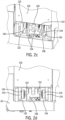
FIG. 2d is a front view of the battery assembly, the counterweight assembly, and the material handling vehicle ofFIG. 2c . -
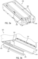
FIG. 3a is a perspective view of a counterweight assembly according to one embodiment of the invention. -
FIG. 3b is a perspective view of a battery assembly according to one embodiment of the invention. -
FIG. 4a is a perspective view of the counterweight assembly ofFIG. 3a with a material handling vehicle. -
FIG. 4b is a perspective view of the battery assembly ofFIG. 3b with the counterweight assembly and material handling vehicle ofFIG. 4a , where the counterweight assembly is engaged with the material handling vehicle. -
FIG. 4c is a perspective view of the battery assembly, the counterweight assembly, and the material handling vehicle ofFIG. 4b , where the battery assembly is received by the counterweight assembly. -
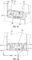
FIG. 4d is a front view of the battery assembly, the counterweight assembly, and the material handling vehicle ofFIG. 4c . -
FIG. 5a is a perspective view of a counterweight assembly according to one embodiment of the invention. -
FIG. 5b is a perspective view of a battery assembly according to one embodiment of the invention. -
FIG. 6a is a perspective view of the counterweight assembly ofFIG. 5a with a material handling vehicle. -
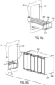
FIG. 6b is a perspective view of the battery assembly ofFIG. 5b with the counterweight assembly and material handling vehicle ofFIG. 6a , where the counterweight assembly is engaged with the material handling vehicle. -
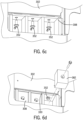
FIG. 6c is a perspective view of the battery assembly, the counterweight assembly, and the material handling vehicle ofFIG. 6b , with a plurality of retention pins coupling the battery assembly to the counterweight assembly. -
FIG. 6d is a perspective view of the battery assembly, the counterweight assembly, the material handling vehicle, and the retention pins ofFIG. 6c , with a plurality of detachable weights retaining the retention pins. -
FIG. 7a is a perspective view of a counterweight assembly according to one embodiment of the invention. -
FIG. 7b is a perspective view of a counterweight assembly according to one embodiment of the invention. -
FIG. 7c is a perspective view of a battery assembly according to one embodiment of the invention. -
FIG. 8a is a perspective view of the counterweight assembly ofFIG. 7a with a material handling vehicle. -
FIG. 8b is a perspective view of the battery assembly ofFIG. 7c with the counterweight assembly and material handling vehicle ofFIG. 8a , where the counterweight assembly is engaged with the material handling vehicle. -
FIG. 9a is a perspective view of a counterweight assembly according to one embodiment of the invention. -
FIG. 9b is a perspective view of a battery assembly according to one embodiment of the invention. -
FIG. 9c is a perspective view of a detachable weight assembly according to one embodiment of the invention. -
FIG. 10a is a perspective view of the counterweight assembly ofFIG. 9a with a material handling vehicle. -
FIG. 10b is a perspective view of the battery assembly ofFIG. 9b with the counterweight assembly and material handling vehicle ofFIG. 10a , where the counterweight assembly is engaged with the material handling vehicle. -
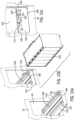
FIG. 10c is a perspective view of the counterweight assembly and material handling vehicle ofFIG. 10b , with a retention pin coupling the counterweight assembly to the material handling vehicle. -
FIG. 11a is a perspective view of the detachable weight ofFIG. 9c with the battery assembly, the counterweight assembly, and the material handling vehicle ofFIG. 10b , where the battery assembly is received by the counterweight assembly. -
FIG. 11b is a perspective view of the detachable weight, the battery assembly, the counterweight assembly, and the material handling vehicle ofFIG. 11a , where the detachable weight is coupled to the counterweight assembly. -
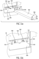
FIG. 12 is a perspective view of a counterweight assembly with a material handling vehicle according to one embodiment of the invention. - The invention may be embodied in several forms without departing from its spirit or essential characteristics. The scope of the invention is defined in the appended claims, rather than in the specific description preceding them. All embodiments that fall within the meaning and range of equivalency of the claims are therefore intended to be embraced by the claims.
- The invention will now be described more specifically with reference to the following embodiments. It is to be noted that the following embodiments are presented herein for purpose of illustration and description only. It is not intended to be exhaustive or to be limited to the precise form disclosed.
- It is to be understood that the phraseology and terminology used herein is for the purpose of description and should not be regarded as limiting. The use of "including," "comprising," or "having" and variations thereof herein is meant to encompass the items listed thereafter and equivalents thereof as well as additional items. Furthermore, the use of "right," "left," "front," "back," "upper," "lower," "above," "below," "top," or "bottom" and variations thereof herein is for the purpose of description and should not be regarded as limiting.
- Unless specified or limited otherwise, the terms "connected" and "coupled" and variations thereof are used broadly and encompass both direct and indirect mountings, connections, supports, and couplings. Further, "connected" and "coupled" are not restricted to physical or mechanical connections or couplings. As used herein, unless expressly stated otherwise, "connected" means that one element/feature is directly or indirectly connected to another element/feature, and not necessarily electrically or mechanically. Likewise, unless expressly stated otherwise, "coupled" means that one element/feature is directly or indirectly coupled to another element/feature, and not necessarily electrically or mechanically. Thus, although schematics shown in the figures depict example arrangements of processing elements, additional intervening elements, devices, features, or components may be present in an actual embodiment.
- As used herein, the terms "component," "system," "device" and the like are intended to refer to either hardware, a combination of hardware and software, software, or software in execution. The word "exemplary" is used herein to mean serving as an example, instance, or illustration. Any aspect or design described herein as "exemplary" is not necessarily to be construed as preferred or advantageous over other aspects or designs.
- Furthermore, the disclosed subject matter may be implemented as a system, method, apparatus, or article of manufacture using standard programming and/or engineering techniques and/or programming to produce hardware, firmware, software, or any combination thereof to implement aspects detailed herein.
- Disclosed herein is a modular battery system including a detachable counterweight assembly and a detachable battery assembly. Embodiments of the modular battery system illustrated in the figures are configured to for use with a material handling vehicle which has a vehicle body and a battery compartment. In other embodiments, however, it should be appreciated that a modular battery system can be configured for use with other material handling vehicles which do not include a battery compartment and which may include additional features not described herein. In still other embodiments, a modular battery system could be used with alternate types of industrial or consumer vehicles.
- In some embodiments, a battery attachment interface and a complimentary counterweight attachment interface can be configured to be engaged with each other to secure the battery assembly to the counterweight assembly. In some embodiments, the interfaces can include attachment features, such as channels and positioning portions, for insertion into and interleaved (and other) engagement with corresponding attachment feature.
- Referring now to the Figures, and more particularly to
FIGS. 1a-2d , an embodiment of amodular battery system 100 configured for use with amaterial handling vehicle 50 is shown. Themodular battery system 100 can include abattery assembly 102 and acounterweight assembly 108 configured to be removably secured to thebattery assembly 102. Thematerial handling vehicle 50 can include abattery compartment 60 dimensioned so that thebattery assembly 102 and thecounterweight assembly 108 can simultaneously fit therein. - The
battery assembly 102 can define a batteryassembly front side 103, a battery assembly backside 104, a battery assembly leftside 105, and a battery assemblyright side 106, and can include abattery base 114 and abattery enclosure 116. Thebattery enclosure 116 can include anenclosure frame 118 configured to house at least onepower source 120 in such a way that eachpower source 120 is removably secured within thebattery enclosure 116, e.g., to thebattery base 114. Additionally or alternatively, at least one of thepower sources 120 can be coupled directly to thebattery base 114 without inclusion of abattery enclosure 116. - Referring to
FIG. 1b , thebattery assembly 102 can further include a battery attachment interface with aleft positioning portion 122 and aright positioning portion 124 which are coupled to and extend downwardly from thebattery base 114 between the battery assembly front andback sides right positioning portions right sides right sides left positioning portion 122 and theright positioning portion 124. Abattery bracket 128 defining a battery bracket opening 129 can be coupled to thebattery base 114 proximate the batteryassembly front side 103, and may be positioned between the left andright positioning portions - The
battery assembly 102 can also include a plurality ofroller bearings 126 which are rotatably coupled to at least one of theleft positioning portion 122 and theright positioning portion 124, eachroller bearing 126 optionally including an adjustable shimming puck (not shown). Theroller bearings 126 can be spaced along the lengths of thepositioning portions battery assembly 102 and thecounterweight assembly 108. In some embodiments, the roller bearings may be part of the battery attachment interface. - It should be appreciated that, in some embodiments, at least one of the
battery enclosure 116, theleft positioning portion 122, theright positioning portion 124, and thebattery bracket 128 may be integrally formed in thebattery base 114. Additionally, the connections between at least one of thebattery base 114, thebattery enclosure 116, theleft positioning portion 122, theright positioning portion 124, thebattery bracket 128, and theroller bearings 126 may be different than the illustrated connections. For example, at least one of theleft positioning portion 122 and theright positioning portion 124 may be coupled directly to thebattery enclosure 116 or to thepower source 120, and theroller bearings 126 may be coupled directly to thebattery base 114. - Referring now to
FIG. 1a , thecounterweight assembly 108 can define a counterweightassembly front side 109, a counterweight assembly backside 110, a counterweight assembly leftside 111, and a counterweight assemblyright side 112, and can include acounterweight base 130. Thecounterweight base 130 can include a counterweight attachment interface with aleft channel 132 and aright channel 134 formed in thecounterweight base 130 between the counterweight assembly front andback sides right sides counterweight base 130 can further include at least onecounterweight bracket 136 defining acounterweight bracket opening 137, and at least one mountingopening 140 formed in thecounterweight base 130. Thecounterweight assembly 108 can also include a counterweight mounting interface with at least onecounterweight mounting feature 142 protruding outwardly from thecounterweight base 130, and the mountingfeature 142 may include at least oneridge 144. In the illustrated embodiment, a mountingfeature 142 extends outwardly from each of the counterweight assembly left andright sides feature 142 includes fiveridges 144 spaced along the mountingfeature 142 between the counterweight assembly front andback sides ridges 144 may vary. - It should be appreciated that at least one of the
left channel 132, theright channel 134, thecounterweight bracket 136, and the mounting features 142 can be integrally formed in thecounterweight base 130 or can be a separate component which is coupled to thecounterweight base 130. Similarly, in some embodiments the mountingopening 140 may be formed in a separate part coupled to thebattery base 114. The mounting features 142 may include alternatively shaped projections in place of theridges 144. For example, cylindrical features (not shown) may be used in some embodiments. - Looking to
FIGS. 2a-2d , thematerial handling vehicle 50 can include a vehicle mounting interface with at least one slot (not shown) formed within thebattery compartment 60. Each slot corresponds to one of theridges 144 of thecounterweight assembly 108 and is configured to engage thecorresponding ridge 144. While at least one slot is engaged with aridge 144, relative motion between thecounterweight assembly 108 and thematerial handling vehicle 50 is restricted. This may be useful, for example, so that thecounterweight assembly 108 is retained in thebattery compartment 60 while the counterweight mounting interface is engaged with the vehicle mounting interface. In some embodiments, a mounting feature of a counterweight mounting interface can be configured to engage another portion of the vehicle mounting interface. For example, a mounting feature can be configured to engage a groove, a notch, a latch, a projection or another structure. Thebattery compartment 60 can further include at least one compartment opening (not shown), wherein each of the compartment openings corresponds to a mountingopening 140. The compartment openings can further be configured so that, when theridges 144 are engaged with the slots, the mountingopenings 140 are concentric with the compartment openings. This can be useful, for example, so that a mountingpin 148 can be inserted into the mountingopening 140 and the compartment opening simultaneously, thereby coupling thecounterweight assembly 108 to thematerial handling vehicle 50. In some embodiments, a bolt or another fastener may be used to secure thecounterweight assembly 108 to thematerial handling vehicle 50. - Referring back to the
counterweight assembly 108 ofFIG. 1a , each of thechannels entry notch 150 proximate the counterweight assemblyfront side 109, and can further be configured so that theleft channel 132 and theright channel 134 can receive theroller bearings 126 coupled to theleft positioning portion 122 and theright positioning portion 124, respectively, through theentry notches 150. Thechannels roller bearings 126 to the left or to the right, and anupper portion 131 of each of thechannels roller bearings 126. Theroller bearings 126 of thebattery assembly 102 can roll along a lower portion of each of thechannels battery assembly 102 moves towards the counterweight assembly backside 110 and at least oneadditional roller bearing 126 enters thechannels entry notches 150. In some embodiments, thebattery assembly 102 may continue rolling until at least one rollingbearing 126 abuts the counterweight assembly backside 110 at the end of thechannels battery assembly 102 is fully received by thecounterweight assembly 108, thebattery bracket 128 and thecounterweight bracket 136 may be positioned so that thebattery bracket opening 129 and thecounterweight bracket opening 137 are concentric with each other. Aretention pin 152 can be inserted through thebattery bracket opening 129 and thecounterweight bracket opening 137, thereby coupling thebattery assembly 102 to thecounterweight assembly 108. In some embodiments, aretainer ring 153 can be attached to theretention pin 152 to retain theretention pin 152 in thebattery bracket opening 129 and thecounterweight bracket opening 137. - As illustrated in
FIGS. 2a-2d , thebattery assembly 102 can be coupled to thematerial handling vehicle 50. InFIG. 2a , thecounterweight assembly 108 can be maneuvered into thebattery compartment 60 through acompartment opening 65, leading with the counterweight assembly backside 110, so that thecounterweight assembly 108 is fully inserted in thebattery compartment 60 and the counterweight assemblyfront side 109 is positioned proximate thecompartment opening 65. Thecounterweight assembly 108 can then be maneuvered to engage the counterweight mounting interface with the vehicle mounting interface. For example, thecounterweight assembly 108 can be maneuvered downward so theridges 144 of thecounterweight assembly 108 engage the slots of thematerial handling vehicle 50. Looking toFIG. 2b , the mountingpins 148 can be inserted into the mountingopenings 140 and the corresponding enclosure openings, thereby coupling thecounterweight assembly 108 to thematerial handling vehicle 50. After thecounterweight assembly 108 has been secured to thematerial handling vehicle 50, thebattery assembly 102 can be maneuvered to slide thebattery assembly 102 into thebattery compartment 60, engaging the battery attachment interface with the counterweight attachment interface. For example, thebattery assembly 102 can be maneuvered so the set ofroller bearings 126 closest to the batteryassembly front side 103 enter thechannels entry notches 150 and thebattery assembly 102 is rolled into thebattery compartment 60. Once the battery attachment interface is fully received by the counterweight attachment interface, as illustrated inFIGS. 2c-2d , theretention pin 152 can be inserted through thebattery bracket opening 129 and thecounterweight bracket opening 137, thereby securing thebattery assembly 102 to thecounterweight assembly 108 and indirectly to thematerial handling vehicle 50. - In other embodiments, other configurations are possible, including configurations that are substantially reversed from those discussed above. For example, at least one of the
positioning portions 122, 124 (or alternative embodiments thereof) can be provided on the counterweight attachment interface, and thechannels 132, 143 (or alternative embodiments thereof) can be provided on a corresponding battery attachment interface. Similarly, at least one ridge 142 (or an alternative embodiment of a mounting feature) can be provided on a vehicle mounting interface, and a corresponding counterweight mounting interface can include a slot (or another structural feature) configured to be engaged by the ridge on the vehicle mounting interface. - Referring now to
FIGS. 3a-4d , another embodiment of a modular battery system 200 including abattery assembly 202 and acounterweight assembly 208 is illustrated. In the illustrated embodiment, aleft positioning portion 222 and aright positioning portion 224 can respectively include aleft channel 223 and aright channel 225, and thecounterweight assembly 208 can include a plurality ofroller bearings 226 rotatably coupled to acounterweight base 230. The left andright channels bearings 226 so that the rollingbearings 226 are retained in the left andright channels roller bearings 226 may provide a rolling interface between thebattery assembly 202 and thecounterweight assembly 208. This may be useful, for example, so that thebattery assembly 202 can be rolled into position to be removably coupled to thecounterweight assembly 208. - Looking to
FIGS. 5a-6d , another embodiment of amodular battery system 300 including abattery assembly 302 and acounterweight assembly 308 is illustrated. In the illustrated embodiment, thebattery assembly 302 can include abattery base 314 with a plurality ofbattery retention openings 356 formed in alower surface 358 of thebattery base 314. Thecounterweight assembly 308 can include acounterweight base 330 which may have a plurality ofcounterweight retention openings 360 formed in anupper surface 362 of thecounterweight base 330. Thecounterweight assembly 308 can further include at least onenon-metal slide 364 coupled to theupper surface 362 of thecounterweight base 360. Thenon-metal slide 364 can provide a sliding interface with thelower surface 358 of thebattery base 314. The sliding interface may be a low-friction interface that produces reduced friction forces compared to a metal-metal interface. In some embodiments, a sliding interface can be formed between thelower surface 358 of thebattery base 314 and theupper surface 362 of thecounterweight base 330, and no non-metal slides 364 are included. Thelower surface 358 of thebattery base 314 can be received by theupper surface 362 of thecounterweight base 330 so that thebattery assembly 302 can be slid into position to be retained once thecounterweight assembly 308 is in thebattery compartment 60. In some embodiments, at least onecounterweight retention plate 349 can be coupled to thematerial handling vehicle 50 inside thebattery compartment 60 and above thecounterweight assembly 308. Thecounterweight retention plate 349 can be configured for retaining thecounterweight assembly 308 within thematerial handling vehicle 50. A plurality of retention pins 352 can be configured to simultaneously engage thebattery retention openings 356 and thecounterweight retention openings 360 to couple thebattery base 314 to thecounterweight base 330. At least one filler blocks 382 can be coupled to thecounterweight base 330 proximate the retention pins 352 so that the retention pins 352 are retained in thebattery retention openings 356 and thecounterweight retention openings 360. - With reference to
FIGS. 7a, 7c , and8a-8b , yet another embodiment of a modular battery system 400 including abattery assembly 402 and acounterweight assembly 408a is illustrated. Here, thebattery assembly 402 can include a battery base 412 and onepositioning portion 468 coupled to thebattery base 414. Thepositioning portion 468 can extend downwardly from thebattery base 414, and can be positioned centrally with respect to thebattery base 414. Thecounterweight assembly 408 can include a counterweight base 430 with a centrally positionedchannel 470 defined by aleft wall 472 and aright wall 474. A plurality ofroller bearings 426 can be rotatably coupled to the left andright walls roller bearings 426 may be positioned inrecesses 476 formed in the left andright walls roller bearings 426 can provide a rolling interface between thebattery base 402 and the left andright walls - The
battery assembly 402 can be rolled on theroller bearings 426 so that thepositioning portion 468 is received in thechannel 470 through afirst entryway 471. Once thepositioning portion 468 is fully received in thechannel 470, aretention plate 478 can be coupled to the counterweight base 430 with at least onefastener 479 so that thefirst entryway 471 is blocked by theretention plate 478, thereby coupling thebattery assembly 402 and thecounterweight assembly 408a. Anadditional retention bolt 480 can be used to further secure thebattery assembly 402 to thecounterweight assembly 408a. In some embodiments, thechannel 470 can run the entire length of the counterweight base 430 and anadditional retention plate 478 may be utilized to block asecond entryway 477 on the opposite side of thechannel 470 as thefirst entryway 471. - In some embodiments, a
counterweight base 408b (FIG. 7 ) having at least onenonmetal slide 464 coupled to each of the left andright walls counterweight base 408 in the modular battery system 400. - Referring now to
FIGS. 9a-11b , an embodiment of a modular battery system 500 including abattery assembly 502, acounterweight assembly 508, and adetachable weight 582 is illustrated. Thebattery assembly 502 can include aleft positioning portion 522 and aright positioning portion 524 with at least onebattery retention opening 556 formed in at least one of theleft positioning portion 522 and theright positioning portion 524. Thecounterweight assembly 508 can include aleft channel 532 and aright channel 534 coupled to acounterweight base 530, and acentral void 584 formed between the left channel andright channels counterweight retention openings 557 corresponding to abattery retention opening 556 can be formed in at least one of theleft channel 532 and theright channel 534 so that onecounterweight retention opening 557 is formed on either side of the left orright channel counterweight retention openings 557 are concentric. - The left and
right channels battery assembly 502 to be slid into position to be coupled with thecounterweight assembly 508. Aretention pin 552 can be inserted into one of thecounterweight retention opening 557 from the side of thecentral void 584 so that theretention pin 552 engages both of the pair ofcounterweight retention openings 557 and the correspondingbattery retention opening 556. Thedetachable weight 582 can be inserted into thecentral void 584 and may be coupled to thecounterweight base 530 with at least onebolt 566. Once inserted, thedetachable weight 582 retains the retention pins 552 in thebattery retention openings 556 and thecounterweight retention opening 557, thereby coupling thebattery base 514 to thecounterweight base 530. - In some embodiments, for example as illustrated in
FIG. 12 , the counterweight mounting interface of acounterweight assembly 608 can include at least onepositioning notch 690 formed in the bottom of thecounterweight base 630. Thepositioning notches 690 can run longitudinally across the counterweight base and can be parallel to each other. Each one of thepositioning notches 690 can be configures to receive apositioning bar 692, which may be part of the vehicle mounting interface and can be coupled to thematerial handling vehicle 50. The positioning bars 692 can be configured to restrict the motion of thecounterweight assembly 108 with respect to thematerial handling vehicle 50 when the positioning bars 692 are engaged with thepositioning notches 690. In some embodiments, the positioning bars 692 may be connected to apositioning bar frame 694 which can be coupled to the material handling vehicle. Additionally or alternatively, at least one positioning bar can be a separate part that is individually coupled to thematerial handling vehicle 50, and at least one positioning bar can be integrally formed in thematerial handling vehicle 50. - Some embodiments of a modular battery system can include additional components configured to perform functions related to the operation of a material handling vehicle. For example, as illustrated in
FIG. 1a , acounterweight assembly 108 can include a grease fitting assembly configured to supply grease to a steering linkage of thematerial handling vehicle 50. A grease manifold can be positioned on the counterweight assemblyfront side 109, and a supply hose can extend from the grease manifold, through thecounterweight base 130, to an outlet on the bottom of thecounterweight assembly 108. The position of the outlet may corresponds to the position of the steering manifold when thecounterweight assembly 108 is positioned within thebattery compartment 60. As illustrated inFIGS. 2c and 2d , the grease manifold may be accessible while thecounterweight assembly 108 and thebattery assembly 102 are received in thebattery compartment 60. This may be useful, for example, in order to provide grease to a steering manifold without removing thebattery assembly 102 or thecounterweight assembly 108. In some embodiments, a grease fitting assembly can have a different configuration. For example, a grease fitting assembly can be positioned on the battery assembly or the material handling vehicle, and a grease fitting assembly can be configured to supply grease to a steering manifold that is in a different location on a material handling vehicle. - The foregoing has been a detailed description of illustrative embodiments of the invention. Various modifications and additions can be made without departing from the spirit and scope thereof. Furthermore, since numerous modifications and changes will readily occur to those skilled in the art, it is not desired to limit the invention to the exact construction and operation shown and described. For example, any of the various features described herein can be combined with some or all of the other features described herein according to alternate embodiments. While the preferred embodiment has been described, the details may be changed without departing from the invention, which is defined by the claims.
- Finally, it is expressly contemplated that any of the processes or steps described herein may be combined, eliminated, or reordered. In other embodiments, instructions may reside in computer readable medium wherein those instructions are executed by a processor to perform one or more of processes or steps described herein. As such, it is expressly contemplated that any of the processes or steps described herein can be implemented as hardware, software, including program instructions executing on a computer, or a combination of hardware and software. Accordingly, this description is meant to be taken only by way of example, and not to otherwise limit the scope of this invention.
Claims (14)
- A modular battery system for a material handling vehicle (50), the modular battery system comprising:a battery assembly (102) including a battery base (114) configured to support a power source (120), the battery base (114) including a battery attachment interface;a counterweight assembly (108) including a counterweight base with a counterweight attachment interface configured to slidably engage the battery attachment interface to selectively secure the battery assembly (102) to the counterweight assembly (108); anda retention pin (152) configured to be manually engaged with a first opening (129) in the battery attachment interface and a second opening (137) in the counterweight attachment interface to restrict movement of the battery assembly (102) relative to the counterweight assembly (108).
- The system of claim 1, wherein one of the battery attachment interface and the counterweight attachment interface is configured as a first attachment interface that includes a positioning portion (122);the other of the battery attachment interface and the counterweight attachment interface is configured as a second attachment interface that includes a channel (132) configured to slidably receive the positioning portion (122); andwherein movement of the battery assembly (102) with respect to the counterweight assembly (108) is restricted in at least one direction when the positioning portion is received in the channel (132).
- The system of claim 2, wherein the positioning portion is a left positioning portion (122) and the first attachment interface includes an additional positioning portion configured as a right positioning portion (124);
the channel (132) is a left channel (132) for engaging the left positioning portion and the second attachment interface includes an additional channel configured as a right channel (134) for engaging the right positioning portion (124). - The system of any of the claims above, wherein at least one of the battery attachment interface and the counterweight attachment interface includes a roller bearing (126) configured to provide a rolling interface between the battery attachment interface and the counterweight attachment interface.
- The system of claim 4, wherein the roller bearing (126) includes a shimming puck for adjusting a position of the roller bearing (126).
- The system of claim 1, wherein at least one of the battery attachment interface and the counterweight attachment interface includes a non-metal slide (364) configured to provide a sliding interface between the battery attachment interface and the counterweight attachment interface.
- The system of claim 1, wherein the first opening (129) is formed in a battery bracket (128) and the second opening (137) is formed in a counterweight bracket (136).
- The system of claim 1 or 7, further comprising a detachable weight configured to be secured to the counterweight assembly (108); and
wherein the detachable weight inhibits disengagement of the retention pin (152) from the first opening (129) and the second opening (137). - The system of any of the claims above, further comprising a retention plate configured to be manually secured to at least one of the battery assembly (102) and the counterweight assembly (108) to restrict movement of the battery assembly (102) relative to the counterweight assembly (108).
- A material handling vehicle (50) comprising:a vehicle body including a battery compartment (60);a counterweight assembly (108) having a first opening (137), the counter weight assembly being configured to be received in the battery compartment (60);a battery assembly (102) including an energy source for powering the material handling vehicle (50), and having a second opening (129), the battery assembly (102) being configured to be slidably received by the counterweight assembly (108); anda retention pin (152) configured to be manually engaged with the first opening (137) and the second opening (129) to restrict movement of the battery assembly (102) relative to the counterweight assembly (108).
- The material handling vehicle (50) of claim 10, whereinthe vehicle body includes a vehicle mounting interface positioned within the battery compartment (60), and the counterweight assembly (108) includes a counterweight mounting interface configured to be manually engaged with the vehicle mounting interface;one of the vehicle mounting interface and the counterweight mounting interface is configured as a first mounting interface that includes a mounting feature (142); andthe other of the vehicle mounting interface and the counterweight mounting interface is configured as a second mounting interface configured to be engaged by the mounting feature (142); andwherein movement of the counterweight assembly (108) with respect to the vehicle body is restricted in at least one direction when the mounting feature (142) is engaged with the second mounting interface.
- The material handling vehicle (50) of claim 11, wherein the mounting feature (142) is configured as a ridge (144) and the second mounting interface includes a slot configured to receive the ridge (144).
- The material handling vehicle (50) of claim 11, wherein the first mounting interface includes a positioning bar extending across the counterweight assembly (108) or the battery compartment (60); and
wherein the second mounting interface includes a slot configured to receive the positioning bar. - The material handling vehicle (50) of claim 10, further comprising a mounting pin (148) configured to be manually engaged with a first mounting opening (140) in the vehicle mounting interface and a second mounting opening (140) in the counterweight mounting interface to restrict movement of the counterweight assembly (108) relative to the vehicle body.
Applications Claiming Priority (1)
| Application Number | Priority Date | Filing Date | Title |
|---|---|---|---|
| US201862715888P | 2018-08-08 | 2018-08-08 |
Publications (3)
| Publication Number | Publication Date |
|---|---|
| EP3608990A1 EP3608990A1 (en) | 2020-02-12 |
| EP3608990C0 EP3608990C0 (en) | 2023-12-13 |
| EP3608990B1 true EP3608990B1 (en) | 2023-12-13 |
Family
ID=67551241
Family Applications (1)
| Application Number | Title | Priority Date | Filing Date |
|---|---|---|---|
| EP19190438.2A Active EP3608990B1 (en) | 2018-08-08 | 2019-08-07 | Systems and methods for a modular battery system |
Country Status (5)
| Country | Link |
|---|---|
| US (1) | US11065967B2 (en) |
| EP (1) | EP3608990B1 (en) |
| CN (1) | CN110834527B (en) |
| AU (1) | AU2019213323B2 (en) |
| CA (1) | CA3051395A1 (en) |
Families Citing this family (7)
| Publication number | Priority date | Publication date | Assignee | Title |
|---|---|---|---|---|
| US11233291B2 (en) | 2019-04-03 | 2022-01-25 | The Raymond Corporation | Systems and methods for a modular battery system |
| US11820635B2 (en) | 2019-04-05 | 2023-11-21 | The Raymond Corporation | Systems and methods for positioning a counterweight on a material handling vehicle |
| CN114537112A (en) * | 2020-11-24 | 2022-05-27 | 奥动新能源汽车科技有限公司 | Battery bracket and electric automobile |
| CN114436174B (en) * | 2022-04-11 | 2022-07-05 | 杭叉集团股份有限公司 | Framework forward-moving type forklift special for lithium battery |
| EP4614703A4 (en) * | 2022-11-14 | 2025-12-17 | Contemporary Amperex Technology Hong Kong Ltd | BATTERY CASE, BATTERY, ELECTRICAL DEVICE AND ENERGY STORAGE SYSTEM |
| JP7513130B1 (en) * | 2023-02-01 | 2024-07-09 | いすゞ自動車株式会社 | Regulating Device |
| FR3150743A1 (en) * | 2023-07-05 | 2025-01-10 | Vincent ROBIN | Power supply module intended to replace a construction machine counterweight, integrating a chassis supporting a set of batteries and a device for installing/removing the set of batteries. |
Family Cites Families (24)
| Publication number | Priority date | Publication date | Assignee | Title |
|---|---|---|---|---|
| US6265091B1 (en) | 1997-06-06 | 2001-07-24 | Johnson Controls Technology Company | Modular electric storage battery |
| US20030070850A1 (en) | 2001-02-16 | 2003-04-17 | Cellex Power Products, Inc. | Hybrid power supply apparatus for battery replacement applications |
| DE102005051058A1 (en) | 2005-10-25 | 2007-04-26 | Still Gmbh | Industrial truck in particular counter weight pallet truck, comprises tray for battery moving on separate roller conveyor for exchange |
| DE102005051015A1 (en) * | 2005-10-25 | 2007-04-26 | Linde Ag | Industrial truck in particular counterweight fork lift, comprises battery exchange unit with swivel mounted holding elements |
| EP1985767B1 (en) | 2006-02-07 | 2017-03-22 | Takeuchi MFG.Co.,Ltd. | Electrically-driven industrial vehicle |
| DE102006031461A1 (en) | 2006-07-07 | 2008-01-10 | Jungheinrich Aktiengesellschaft | Battery replacement system for a battery-operated truck |
| DE102006055363A1 (en) | 2006-11-23 | 2008-06-26 | Still Gmbh | Forklift with a guide for pulling a battery block sideways |
| DE102007031149A1 (en) * | 2007-07-05 | 2009-01-08 | Jungheinrich Aktiengesellschaft | Industrial truck, in particular forklift |
| JP2009161138A (en) * | 2008-01-10 | 2009-07-23 | Yamaha Motor Co Ltd | Motorcycle power supply support mechanism and motorcycle equipped with the same |
| JP2009274651A (en) | 2008-05-16 | 2009-11-26 | Toyota Industries Corp | Hybrid industrial vehicle |
| JP3148747U (en) * | 2008-12-12 | 2009-02-26 | 株式会社豊田自動織機 | Electric car |
| US8292015B2 (en) * | 2010-07-21 | 2012-10-23 | Caterpillar Global Mining America Llc | Battery-powered mining vehicle |
| KR101316432B1 (en) * | 2011-12-01 | 2013-10-08 | 기아자동차주식회사 | Battery pack mounting structure of vehicle |
| US8980456B2 (en) * | 2011-12-22 | 2015-03-17 | GM Global Technology Operations LLC | Module mounting and structure with adaptor plate |
| US8852794B2 (en) | 2012-01-18 | 2014-10-07 | Battchange, Llc | Electric vehicle battery case |
| WO2013143460A1 (en) | 2012-03-27 | 2013-10-03 | 台湾立凯绿能移动股份有限公司 | Fixing device group for removable battery of electric vehicle, and locking method thereof |
| CN104040754B (en) | 2013-01-08 | 2016-02-10 | 株式会社小松制作所 | Work machine accumulator housing, Work machine secondary battery unit, battery-type Work machine and battery-type fork truck |
| JP5621859B2 (en) | 2013-01-25 | 2014-11-12 | 株式会社豊田自動織機 | Battery module |
| JP5664690B2 (en) * | 2013-03-29 | 2015-02-04 | 株式会社豊田自動織機 | Battery pack |
| US9193316B2 (en) * | 2013-05-20 | 2015-11-24 | GM Global Technology Operations LLC | Battery enclosure systems and methods |
| DE102013216399A1 (en) | 2013-08-19 | 2015-02-19 | Jungheinrich Aktiengesellschaft | Battery operated work vehicle, in particular industrial truck |
| US10294089B2 (en) * | 2015-12-03 | 2019-05-21 | The Raymond Corporation | Systems and methods for a material handling vehicle with a floor suspension |
| AU2017201690B2 (en) * | 2016-03-14 | 2022-09-15 | The Raymond Corporation | Battery counterweight system |
| CN206955569U (en) * | 2017-06-09 | 2018-02-02 | 浙江加力仓储设备股份有限公司 | A kind of shift-forward type electri forklift vehicle frame |
-
2019
- 2019-08-06 AU AU2019213323A patent/AU2019213323B2/en active Active
- 2019-08-07 CA CA3051395A patent/CA3051395A1/en active Pending
- 2019-08-07 EP EP19190438.2A patent/EP3608990B1/en active Active
- 2019-08-07 US US16/534,700 patent/US11065967B2/en active Active
- 2019-08-08 CN CN201910730127.1A patent/CN110834527B/en active Active
Also Published As
| Publication number | Publication date |
|---|---|
| EP3608990C0 (en) | 2023-12-13 |
| US11065967B2 (en) | 2021-07-20 |
| CN110834527B (en) | 2024-08-20 |
| AU2019213323A1 (en) | 2020-02-27 |
| EP3608990A1 (en) | 2020-02-12 |
| US20200047630A1 (en) | 2020-02-13 |
| AU2019213323B2 (en) | 2024-08-29 |
| CA3051395A1 (en) | 2020-02-08 |
| CN110834527A (en) | 2020-02-25 |
Similar Documents
| Publication | Publication Date | Title |
|---|---|---|
| AU2019213323B2 (en) | Systems and methods for a modular battery system | |
| EP3719862B1 (en) | Systems and methods for a modular battery system | |
| US12102225B2 (en) | Shelving support bracket assembly | |
| US6641236B2 (en) | Cabinet with drawer retainer/locking system | |
| US20150108303A1 (en) | Adaptable u-shaped bracket assemblies for a load stop pallet rack system | |
| US10283983B2 (en) | Repositionable shelf system for device charging and storage cabinets or carts | |
| CN206437488U (en) | A kind of intelligent commodity shelf | |
| EP3309007A1 (en) | Adjustable armrest systems and methods for a material handling vehicle | |
| JP2000023802A (en) | Commodity display unit | |
| US20220094186A1 (en) | Storage and charging station system for mobile electronic devices having a unitary support tower cage structure | |
| US7007786B2 (en) | Conveyor apparatus on a cargo deck of an aircraft | |
| JP6993194B2 (en) | Shelf equipment | |
| HK40023244A (en) | Systems and methods for a modular battery system | |
| HK40037917A (en) | Systems and methods for a modular battery system | |
| HK40023244B (en) | Systems and methods for a modular battery system | |
| CN209871579U (en) | Material discharging machine | |
| CN110693254B (en) | Goods shelf convenient for finding goods | |
| JP5999656B2 (en) | French drop | |
| CN108158228B (en) | Adjustable goods channel and dividing shelf | |
| CN219619639U (en) | Battery type-changing tray | |
| JP4662646B2 (en) | Prefabricated cabinet | |
| JP2002065422A (en) | Stage box | |
| CN210823245U (en) | Storage basket | |
| JP2022074239A (en) | Cart device | |
| KR970006594Y1 (en) | Assembling cabinet |
Legal Events
| Date | Code | Title | Description |
|---|---|---|---|
| PUAI | Public reference made under article 153(3) epc to a published international application that has entered the european phase |
Free format text: ORIGINAL CODE: 0009012 |
|
| STAA | Information on the status of an ep patent application or granted ep patent |
Free format text: STATUS: THE APPLICATION HAS BEEN PUBLISHED |
|
| AK | Designated contracting states |
Kind code of ref document: A1 Designated state(s): AL AT BE BG CH CY CZ DE DK EE ES FI FR GB GR HR HU IE IS IT LI LT LU LV MC MK MT NL NO PL PT RO RS SE SI SK SM TR |
|
| AX | Request for extension of the european patent |
Extension state: BA ME |
|
| STAA | Information on the status of an ep patent application or granted ep patent |
Free format text: STATUS: REQUEST FOR EXAMINATION WAS MADE |
|
| 17P | Request for examination filed |
Effective date: 20200812 |
|
| RBV | Designated contracting states (corrected) |
Designated state(s): AL AT BE BG CH CY CZ DE DK EE ES FI FR GB GR HR HU IE IS IT LI LT LU LV MC MK MT NL NO PL PT RO RS SE SI SK SM TR |
|
| REG | Reference to a national code |
Ref country code: DE Ref legal event code: R079 Free format text: PREVIOUS MAIN CLASS: H01M0002100000 Ipc: H01M0050249000 Ref country code: DE Ref legal event code: R079 Ref document number: 602019043128 Country of ref document: DE Free format text: PREVIOUS MAIN CLASS: H01M0002100000 Ipc: H01M0050249000 |
|
| GRAP | Despatch of communication of intention to grant a patent |
Free format text: ORIGINAL CODE: EPIDOSNIGR1 |
|
| STAA | Information on the status of an ep patent application or granted ep patent |
Free format text: STATUS: GRANT OF PATENT IS INTENDED |
|
| RIC1 | Information provided on ipc code assigned before grant |
Ipc: B66F 9/075 20060101ALI20230605BHEP Ipc: B60L 50/64 20190101ALI20230605BHEP Ipc: B60K 1/04 20190101ALI20230605BHEP Ipc: H01M 50/249 20210101AFI20230605BHEP |
|
| INTG | Intention to grant announced |
Effective date: 20230703 |
|
| GRAS | Grant fee paid |
Free format text: ORIGINAL CODE: EPIDOSNIGR3 |
|
| GRAA | (expected) grant |
Free format text: ORIGINAL CODE: 0009210 |
|
| STAA | Information on the status of an ep patent application or granted ep patent |
Free format text: STATUS: THE PATENT HAS BEEN GRANTED |
|
| AK | Designated contracting states |
Kind code of ref document: B1 Designated state(s): AL AT BE BG CH CY CZ DE DK EE ES FI FR GB GR HR HU IE IS IT LI LT LU LV MC MK MT NL NO PL PT RO RS SE SI SK SM TR |
|
| RAP3 | Party data changed (applicant data changed or rights of an application transferred) |
Owner name: THE RAYMOND CORPORATION |
|
| REG | Reference to a national code |
Ref country code: GB Ref legal event code: FG4D |
|
| REG | Reference to a national code |
Ref country code: CH Ref legal event code: EP |
|
| REG | Reference to a national code |
Ref country code: DE Ref legal event code: R096 Ref document number: 602019043128 Country of ref document: DE |
|
| REG | Reference to a national code |
Ref country code: IE Ref legal event code: FG4D |
|
| U01 | Request for unitary effect filed |
Effective date: 20231220 |
|
| U07 | Unitary effect registered |
Designated state(s): AT BE BG DE DK EE FI FR IT LT LU LV MT NL PT SE SI Effective date: 20240103 |
|
| PG25 | Lapsed in a contracting state [announced via postgrant information from national office to epo] |
Ref country code: GR Free format text: LAPSE BECAUSE OF FAILURE TO SUBMIT A TRANSLATION OF THE DESCRIPTION OR TO PAY THE FEE WITHIN THE PRESCRIBED TIME-LIMIT Effective date: 20240314 |
|
| PG25 | Lapsed in a contracting state [announced via postgrant information from national office to epo] |
Ref country code: ES Free format text: LAPSE BECAUSE OF FAILURE TO SUBMIT A TRANSLATION OF THE DESCRIPTION OR TO PAY THE FEE WITHIN THE PRESCRIBED TIME-LIMIT Effective date: 20231213 |
|
| PG25 | Lapsed in a contracting state [announced via postgrant information from national office to epo] |
Ref country code: GR Free format text: LAPSE BECAUSE OF FAILURE TO SUBMIT A TRANSLATION OF THE DESCRIPTION OR TO PAY THE FEE WITHIN THE PRESCRIBED TIME-LIMIT Effective date: 20240314 Ref country code: ES Free format text: LAPSE BECAUSE OF FAILURE TO SUBMIT A TRANSLATION OF THE DESCRIPTION OR TO PAY THE FEE WITHIN THE PRESCRIBED TIME-LIMIT Effective date: 20231213 |
|
| PG25 | Lapsed in a contracting state [announced via postgrant information from national office to epo] |
Ref country code: RS Free format text: LAPSE BECAUSE OF FAILURE TO SUBMIT A TRANSLATION OF THE DESCRIPTION OR TO PAY THE FEE WITHIN THE PRESCRIBED TIME-LIMIT Effective date: 20231213 Ref country code: NO Free format text: LAPSE BECAUSE OF FAILURE TO SUBMIT A TRANSLATION OF THE DESCRIPTION OR TO PAY THE FEE WITHIN THE PRESCRIBED TIME-LIMIT Effective date: 20240313 Ref country code: HR Free format text: LAPSE BECAUSE OF FAILURE TO SUBMIT A TRANSLATION OF THE DESCRIPTION OR TO PAY THE FEE WITHIN THE PRESCRIBED TIME-LIMIT Effective date: 20231213 |
|
| PG25 | Lapsed in a contracting state [announced via postgrant information from national office to epo] |
Ref country code: IS Free format text: LAPSE BECAUSE OF FAILURE TO SUBMIT A TRANSLATION OF THE DESCRIPTION OR TO PAY THE FEE WITHIN THE PRESCRIBED TIME-LIMIT Effective date: 20240413 |
|
| PG25 | Lapsed in a contracting state [announced via postgrant information from national office to epo] |
Ref country code: CZ Free format text: LAPSE BECAUSE OF FAILURE TO SUBMIT A TRANSLATION OF THE DESCRIPTION OR TO PAY THE FEE WITHIN THE PRESCRIBED TIME-LIMIT Effective date: 20231213 |
|
| PG25 | Lapsed in a contracting state [announced via postgrant information from national office to epo] |
Ref country code: SK Free format text: LAPSE BECAUSE OF FAILURE TO SUBMIT A TRANSLATION OF THE DESCRIPTION OR TO PAY THE FEE WITHIN THE PRESCRIBED TIME-LIMIT Effective date: 20231213 |
|
| PG25 | Lapsed in a contracting state [announced via postgrant information from national office to epo] |
Ref country code: SM Free format text: LAPSE BECAUSE OF FAILURE TO SUBMIT A TRANSLATION OF THE DESCRIPTION OR TO PAY THE FEE WITHIN THE PRESCRIBED TIME-LIMIT Effective date: 20231213 Ref country code: SK Free format text: LAPSE BECAUSE OF FAILURE TO SUBMIT A TRANSLATION OF THE DESCRIPTION OR TO PAY THE FEE WITHIN THE PRESCRIBED TIME-LIMIT Effective date: 20231213 Ref country code: RO Free format text: LAPSE BECAUSE OF FAILURE TO SUBMIT A TRANSLATION OF THE DESCRIPTION OR TO PAY THE FEE WITHIN THE PRESCRIBED TIME-LIMIT Effective date: 20231213 Ref country code: IS Free format text: LAPSE BECAUSE OF FAILURE TO SUBMIT A TRANSLATION OF THE DESCRIPTION OR TO PAY THE FEE WITHIN THE PRESCRIBED TIME-LIMIT Effective date: 20240413 Ref country code: CZ Free format text: LAPSE BECAUSE OF FAILURE TO SUBMIT A TRANSLATION OF THE DESCRIPTION OR TO PAY THE FEE WITHIN THE PRESCRIBED TIME-LIMIT Effective date: 20231213 |
|
| PG25 | Lapsed in a contracting state [announced via postgrant information from national office to epo] |
Ref country code: PL Free format text: LAPSE BECAUSE OF FAILURE TO SUBMIT A TRANSLATION OF THE DESCRIPTION OR TO PAY THE FEE WITHIN THE PRESCRIBED TIME-LIMIT Effective date: 20231213 |
|
| U20 | Renewal fee for the european patent with unitary effect paid |
Year of fee payment: 6 Effective date: 20240705 |
|
| PG25 | Lapsed in a contracting state [announced via postgrant information from national office to epo] |
Ref country code: PL Free format text: LAPSE BECAUSE OF FAILURE TO SUBMIT A TRANSLATION OF THE DESCRIPTION OR TO PAY THE FEE WITHIN THE PRESCRIBED TIME-LIMIT Effective date: 20231213 |
|
| REG | Reference to a national code |
Ref country code: DE Ref legal event code: R097 Ref document number: 602019043128 Country of ref document: DE |
|
| PLBE | No opposition filed within time limit |
Free format text: ORIGINAL CODE: 0009261 |
|
| STAA | Information on the status of an ep patent application or granted ep patent |
Free format text: STATUS: NO OPPOSITION FILED WITHIN TIME LIMIT |
|
| 26N | No opposition filed |
Effective date: 20240916 |
|
| REG | Reference to a national code |
Ref country code: CH Ref legal event code: PL |
|
| PG25 | Lapsed in a contracting state [announced via postgrant information from national office to epo] |
Ref country code: MC Free format text: LAPSE BECAUSE OF FAILURE TO SUBMIT A TRANSLATION OF THE DESCRIPTION OR TO PAY THE FEE WITHIN THE PRESCRIBED TIME-LIMIT Effective date: 20231213 Ref country code: CH Free format text: LAPSE BECAUSE OF NON-PAYMENT OF DUE FEES Effective date: 20240831 |
|
| PGFP | Annual fee paid to national office [announced via postgrant information from national office to epo] |
Ref country code: GB Payment date: 20250619 Year of fee payment: 7 |
|
| PG25 | Lapsed in a contracting state [announced via postgrant information from national office to epo] |
Ref country code: IE Free format text: LAPSE BECAUSE OF NON-PAYMENT OF DUE FEES Effective date: 20240807 |
|
| U20 | Renewal fee for the european patent with unitary effect paid |
Year of fee payment: 7 Effective date: 20250709 |
|
| PG25 | Lapsed in a contracting state [announced via postgrant information from national office to epo] |
Ref country code: CY Free format text: LAPSE BECAUSE OF FAILURE TO SUBMIT A TRANSLATION OF THE DESCRIPTION OR TO PAY THE FEE WITHIN THE PRESCRIBED TIME-LIMIT; INVALID AB INITIO Effective date: 20190807 |
|
| PG25 | Lapsed in a contracting state [announced via postgrant information from national office to epo] |
Ref country code: HU Free format text: LAPSE BECAUSE OF FAILURE TO SUBMIT A TRANSLATION OF THE DESCRIPTION OR TO PAY THE FEE WITHIN THE PRESCRIBED TIME-LIMIT; INVALID AB INITIO Effective date: 20190807 |