EP3608885A1 - Dockingstation für elektronisches zahlungsterminal, entsprechendes elektronisches zahlungsterminal und -system - Google Patents
Dockingstation für elektronisches zahlungsterminal, entsprechendes elektronisches zahlungsterminal und -system Download PDFInfo
- Publication number
- EP3608885A1 EP3608885A1 EP19189817.0A EP19189817A EP3608885A1 EP 3608885 A1 EP3608885 A1 EP 3608885A1 EP 19189817 A EP19189817 A EP 19189817A EP 3608885 A1 EP3608885 A1 EP 3608885A1
- Authority
- EP
- European Patent Office
- Prior art keywords
- docking station
- terminal
- locking means
- payment terminal
- cooperate
- Prior art date
- Legal status (The legal status is an assumption and is not a legal conclusion. Google has not performed a legal analysis and makes no representation as to the accuracy of the status listed.)
- Granted
Links
Images
Classifications
-
- G—PHYSICS
- G07—CHECKING-DEVICES
- G07F—COIN-FREED OR LIKE APPARATUS
- G07F7/00—Mechanisms actuated by objects other than coins to free or to actuate vending, hiring, coin or paper currency dispensing or refunding apparatus
- G07F7/08—Mechanisms actuated by objects other than coins to free or to actuate vending, hiring, coin or paper currency dispensing or refunding apparatus by coded identity card or credit card or other personal identification means
- G07F7/0873—Details of the card reader
-
- H—ELECTRICITY
- H01—ELECTRIC ELEMENTS
- H01R—ELECTRICALLY-CONDUCTIVE CONNECTIONS; STRUCTURAL ASSOCIATIONS OF A PLURALITY OF MUTUALLY-INSULATED ELECTRICAL CONNECTING ELEMENTS; COUPLING DEVICES; CURRENT COLLECTORS
- H01R33/00—Coupling devices specially adapted for supporting apparatus and having one part acting as a holder providing support and electrical connection via a counterpart which is structurally associated with the apparatus, e.g. lamp holders; Separate parts thereof
- H01R33/97—Holders with separate means to prevent loosening of the coupling or unauthorised removal of apparatus held
-
- G—PHYSICS
- G06—COMPUTING OR CALCULATING; COUNTING
- G06F—ELECTRIC DIGITAL DATA PROCESSING
- G06F1/00—Details not covered by groups G06F3/00 - G06F13/00 and G06F21/00
- G06F1/16—Constructional details or arrangements
- G06F1/1613—Constructional details or arrangements for portable computers
- G06F1/1632—External expansion units, e.g. docking stations
-
- G—PHYSICS
- G06—COMPUTING OR CALCULATING; COUNTING
- G06Q—INFORMATION AND COMMUNICATION TECHNOLOGY [ICT] SPECIALLY ADAPTED FOR ADMINISTRATIVE, COMMERCIAL, FINANCIAL, MANAGERIAL OR SUPERVISORY PURPOSES; SYSTEMS OR METHODS SPECIALLY ADAPTED FOR ADMINISTRATIVE, COMMERCIAL, FINANCIAL, MANAGERIAL OR SUPERVISORY PURPOSES, NOT OTHERWISE PROVIDED FOR
- G06Q20/00—Payment architectures, schemes or protocols
- G06Q20/30—Payment architectures, schemes or protocols characterised by the use of specific devices or networks
- G06Q20/34—Payment architectures, schemes or protocols characterised by the use of specific devices or networks using cards, e.g. integrated circuit [IC] cards or magnetic cards
- G06Q20/352—Contactless payments by cards
-
- G—PHYSICS
- G07—CHECKING-DEVICES
- G07G—REGISTERING THE RECEIPT OF CASH, VALUABLES, OR TOKENS
- G07G1/00—Cash registers
- G07G1/0018—Constructional details, e.g. of drawer, printing means, input means
-
- H—ELECTRICITY
- H01—ELECTRIC ELEMENTS
- H01R—ELECTRICALLY-CONDUCTIVE CONNECTIONS; STRUCTURAL ASSOCIATIONS OF A PLURALITY OF MUTUALLY-INSULATED ELECTRICAL CONNECTING ELEMENTS; COUPLING DEVICES; CURRENT COLLECTORS
- H01R13/00—Details of coupling devices of the kinds covered by groups H01R12/70 or H01R24/00 - H01R33/00
- H01R13/62—Means for facilitating engagement or disengagement of coupling parts or for holding them in engagement
- H01R13/629—Additional means for facilitating engagement or disengagement of coupling parts, e.g. aligning or guiding means, levers, gas pressure electrical locking indicators, manufacturing tolerances
- H01R13/631—Additional means for facilitating engagement or disengagement of coupling parts, e.g. aligning or guiding means, levers, gas pressure electrical locking indicators, manufacturing tolerances for engagement only
Definitions
- the invention relates to a docking station for an electronic payment terminal, to an electronic payment terminal, and to an associated electronic payment system.
- electronic payment terminals are mainly used to allow the payment of purchases of goods and services within points of sale.
- Such terminals generally include a smart card reader and a magnetic card reader. They also include a screen, making it possible in particular to view the transaction amounts and a keyboard for entering these same amounts as well as confidential codes entered by customers, or else a touch screen.
- These payment terminals generally have a battery, allowing them to operate independently.
- This battery must be regularly recharged, conventionally by means of a docking station, otherwise known as a docking station, supply base or supply base, on which the mobile payment terminal is placed in a horizontal position. , or close to the horizontal, so that contacts of the terminal come into contact with contacts of the station forming an electrical connection between the supply means of the terminal and the supply means of the station.
- the station can be connected to a computer by a wired link, for example according to the USB standard (from the English “Universal Serial Bus”).
- such a docking station has means for guiding the payment terminal to a supply position, for example in the form of amounts along which the terminal must slide.
- a bad contact on the link connector for example a bad USB contact
- a transaction to fail when the table supporting the docking station and the terminal is subject to vibrations or displacement, due to the fact that occasional losses may appear.
- Such a drawback can prove problematic during network communications for example.
- An objective of the present invention is to at least partially overcome the drawbacks of the prior art.
- the invention aims to overcome at least some of the drawbacks of prior art payment systems.
- the invention aims to provide, in at least one embodiment, an electronic payment terminal docking station making it possible to provide sufficient support to maintain satisfactory electrical contact between the station and the terminal resting on the latter.
- Another objective of at least one embodiment is to implement such a payment system having a limited size.
- Yet another objective of at least one embodiment is to provide such a system which is simple to use and inexpensive to implement.
- a docking station for an electronic payment terminal comprising a reception surface of said payment terminal, said surface. being provided with means for guiding said terminal to a position for connecting said terminal to said docking station.
- the invention proposes a new and inventive approach making it possible to at least partially resolve some of the drawbacks of the prior art.
- the invention provides for a reversible locking of the payment terminal on the station by the use of mobile locking means on the station which may or may not cooperate with fixed complementary locking means located under the payment terminal.
- These locking means serve to hang the terminal on the support element so as to position it correctly and make it fixed to maintain satisfactory electrical contact between the station and the terminal and ensure optimal operation of the assembly.
- the mobile locking means can be retracted to detach the terminal from the station and allow mobile use of the latter.
- the first movable locking means comprise two fingers and in that the second locking means comprise two housings in which the two fingers are housed at least partially when the latter are in position deployed.
- the station further comprises means for actuating the first locking means able to move the first movable locking means from the deployed position to the retracted position.
- the actuating means comprise an unlocking push button extending on a surface opposite to the reception surface, the unlocking push button being mounted pivoting on said docking station and carrying a return spring secured to said docking station.
- the first locking means are able to be moved from the deployed position to the retracted position by manual pressure on the push button.
- At least one mode of the unlocking push button comprises a light intended to cooperate with a Kensington type lock connected to an anti-theft cable.
- the front wall extends substantially perpendicular to the receiving surface
- said guide means comprise at least one side wall extending from a side edge of said reception surface and extending the front wall.
- At least one tongue extends from the rear edge of said reception surface, said at least one tongue being intended to cooperate with a housing formed under the payment terminal so as to prevent the lifting of said terminal in the connection position.
- the invention also relates to an electronic payment terminal which can be positioned on a docking station according to one of the abovementioned embodiments, the terminal comprising second locking means able to cooperate with first complementary locking means provided on a surface reception of the docking station.
- the terminal has a front face comprising at least one recess configured to cooperate with a positioning hook of the docking station and at least one housing provided under the terminal is configured to cooperate with a tab of said docking station.
- orientation and positioning are used “front”, “rear”, “lateral”, arbitrarily referring to a normal position for using a payment terminal and a station. 'Home.
- longitudinal and transverse are also used with reference to directions respectively approximately orthogonal to the front and rear faces of the docking station, and approximately orthogonal to the lateral faces of the docking station.
- an electronic payment system comprising a docking station and an associated electronic payment terminal.
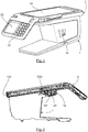
- the electronic payment terminal 2 which can be positioned on a docking station, or base, 1, comprises a magnetic card reader 25A, a smart card reader 25B, at least one screen 20, 23 for viewing transactions , a USB port 16 and an input keyboard 22.
- the electronic payment terminal 2 comprises two screens, namely a first screen 20 allowing for example a merchant to view a connection state of the terminal 2 on the docking station 1 or a progress state of a transaction, and a second screen 23 allowing a client to view for example the amount of a transaction as well as the entry of a confidential code specific to his credit card in order to carry out a transaction.
- a first screen 20 allowing for example a merchant to view a connection state of the terminal 2 on the docking station 1 or a progress state of a transaction
- a second screen 23 allowing a client to view for example the amount of a transaction as well as the entry of a confidential code specific to his credit card in order to carry out a transaction.
- these two screens 20, 23 can, according to one embodiment of the invention, be touch screens.
- the docking station 1 comprises a reception surface 10 of the electronic payment terminal 2.
- Such a reception surface 10 is, in this example, substantially planar.
- This reception surface 10 includes a connector 14 making it possible to establish an electrical connection with the electronic payment terminal 2.
- the reception surface 10 is, as illustrated in particular in Figures 5 and 7 , provided with means for guiding the terminal 2 to a position for connecting the terminal 2 to the docking station 1.
- the electronic payment terminal 2 is placed so that the connector 14 formed on the surface host 10 is connected with communication means 26 (illustrated on the figure 4 ) carried by the lower surface of the terminal 2 opposite the surface carrying the screens 20, 23.
- this connector 14 of the docking station 1 combines electrical charging pins as well as data transfer pins.
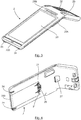
- the docking station 1 also comprises guide means 15 which, in this embodiment, comprise a front wall 100 extending from the front or front edge of the reception surface 10 and having a rectilinear profile curved at its free end complementary to the profile of the front face 200 of the terminal 2.
- the front face 200 of the terminal 2 is intended to be positioned against this front wall 100.
- the means 15 for guiding the reception surface 10 have a front edge, here called the front wall 100, which extends from the front edge, or front edge of the reception surface 10 perpendicular to the reception surface 10.
- a front wall 100 forms a positioning stop for the electronic payment terminal 2 and prevents it from sliding forward or improper positioning thereof too far in front of the station 1, which would result in a poor electrical connection between terminal 2 and docking station 1.
- a docking station and an electronic payment terminal could be implemented, the respective front portion and the front face of which have a profile other than that illustrated.
- the front wall 100 of the docking station 1 is provided with at least one positioning hook or tongue capable of cooperating with a recess 24 formed on the front face 200 of terminal 2.
- hooks 13 and recesses 24 also prevent the terminal 2 from being raised when the latter is positioned on the docking station 1.
- an anti-lifting tongue 17 extends from the rear edge of the reception surface 10 in the plane of the latter. This tongue 17 is intended to cooperate with a housing 27 formed under the terminal 2.
- the front wall 100 is provided with two spaced hooks 13 each cooperating with a recess 24, the two recesses being provided on the front face 200 of terminal 2.
- These two hooks 13 here take the form of rectangular strips positioned in the recesses 24 of complementary shape.
- the means 15 for guiding the reception surface 10 illustrated in this embodiment further comprise a side wall 101 connected to the front wall 100 and extending perpendicular to the reception surface 10.
- the implementation of this side wall 101 aims to prevent the electronic payment terminal 2 from shifting laterally with respect to the reception surface 10, and therefore to the reception station 1.
- the terminal 2 is positioned on the docking station 1 by sliding it from the rear towards the front onto the docking surface 10.
- the hooks 13 and the tongue prevent the lifting of the terminal 2, and of the fingers 1230 described in detail below provide an anti-reverse lockout of the terminal 2 on the docking station 1.
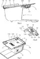
- the docking station 1 comprises means for actuating these first locking means 1230.
- actuating means comprise a push button 12 for unlocking extending over the surface of the docking station 1 opposite to said docking surface 10.
- this push button 12 comprises a hollow oblong cover 121 on which is fixed a return spring 120.
- the cover 121 has two legs 123 in the shape of an "L". Each tab 123 carries an axis 1231 on a lateral edge and a locking finger 1230 whose upper face is inclined.
- the cover 121 is pivotally mounted for pivoting via the pins 1231 on the docking station 1.
- the terminal 2 being locked on the docking station 1, when a user presses, preferably with the help of his index finger, the push button 12 and exerts an upward pressure, the push button 12 pivots around the axes 1231 which causes the passage of the two locking fingers 1230 from their deployed position where they protrude with respect to the reception surface 10 to their retracted position where they are housed in the reception station 1 without protruding from the surface reception 10.
- the first locking means of the docking station 10 which therefore comprise two locking fingers 1230 cooperate with the second locking means 21 of the payment terminal 2.
- the second locking means 21 comprise two "U" shaped housings which are placed opposite the two pins 1230 when the terminal 2 is positioned on the docking station 10.
- the locking fingers 1230 are placed in the housings 21 of the electronic payment terminal which is then locked in translation relative to the station. reception 10, from front to back and laterally.
- the user presses the push button 12 which retracts the fingers 1230 downwards outside the housings 21.
- first locking means have more than two fingers so as, for example, to block other potential movements of the electronic payment terminal relative to the docking station.
- these locking fingers 1230 have the function of preventing the withdrawal of the payment terminal 2 on the docking station 1.
- the cover 121 of the push button 12 has on a lateral edge a through light 122 of substantially oblong shape.
- a through light 122 is intended to cooperate with a Kensington type lock connected to an anti-theft cable so as to secure the installation of the docking station 1.
Landscapes
- Engineering & Computer Science (AREA)
- Physics & Mathematics (AREA)
- General Physics & Mathematics (AREA)
- Theoretical Computer Science (AREA)
- Business, Economics & Management (AREA)
- Computer Hardware Design (AREA)
- Human Computer Interaction (AREA)
- General Engineering & Computer Science (AREA)
- Accounting & Taxation (AREA)
- Strategic Management (AREA)
- General Business, Economics & Management (AREA)
- Computer Networks & Wireless Communication (AREA)
- Microelectronics & Electronic Packaging (AREA)
- Details Of Connecting Devices For Male And Female Coupling (AREA)
- Cash Registers Or Receiving Machines (AREA)
Applications Claiming Priority (1)
| Application Number | Priority Date | Filing Date | Title |
|---|---|---|---|
| FR1857331A FR3084769B1 (fr) | 2018-08-06 | 2018-08-06 | Station d'accueil pour terminal de paiement electronique, terminal et systeme de paiement electronique correspondants |
Publications (2)
| Publication Number | Publication Date |
|---|---|
| EP3608885A1 true EP3608885A1 (de) | 2020-02-12 |
| EP3608885B1 EP3608885B1 (de) | 2025-02-19 |
Family
ID=65201028
Family Applications (1)
| Application Number | Title | Priority Date | Filing Date |
|---|---|---|---|
| EP19189817.0A Active EP3608885B1 (de) | 2018-08-06 | 2019-08-02 | Dockingstation für elektronisches zahlungsterminal, entsprechendes elektronisches zahlungsterminal und -system |
Country Status (5)
| Country | Link |
|---|---|
| US (1) | US10811832B2 (de) |
| EP (1) | EP3608885B1 (de) |
| CA (1) | CA3051221A1 (de) |
| ES (1) | ES3032749T3 (de) |
| FR (1) | FR3084769B1 (de) |
Families Citing this family (5)
| Publication number | Priority date | Publication date | Assignee | Title |
|---|---|---|---|---|
| US9721242B2 (en) * | 2014-10-28 | 2017-08-01 | Poynt Co. | Payment terminal operation method and system therefor |
| USD931363S1 (en) * | 2019-12-10 | 2021-09-21 | Flytech Technology Co., Ltd | Point-of-sale base with object recognition camera module thereon |
| US20230120610A1 (en) * | 2021-10-19 | 2023-04-20 | Jpmorgan Chase Bank, N.A. | Point of sale devices |
| USD1095666S1 (en) * | 2024-03-27 | 2025-09-30 | Pax Computer Technology (Shenzhen) Co., Ltd. | POS terminal |
| USD1095665S1 (en) * | 2024-03-29 | 2025-09-30 | Pax Computer Technology (Shenzhen) Co., Ltd. | POS terminal |
Citations (7)
| Publication number | Priority date | Publication date | Assignee | Title |
|---|---|---|---|---|
| WO2003046710A2 (en) * | 2001-11-29 | 2003-06-05 | Joseph Gadifele Modibane | Commercial electronic communication devices |
| US20040058705A1 (en) * | 2001-12-21 | 2004-03-25 | Russell Morgan | Secure point-of-sale cellular telephone docking module system |
| US20120033375A1 (en) * | 2010-08-04 | 2012-02-09 | Savant Systems Llc | In-wall dock for a tablet computer |
| US20160253668A1 (en) * | 2013-10-07 | 2016-09-01 | Woosim Systems Inc. | Secure payment device |
| US20160275478A1 (en) * | 2008-08-31 | 2016-09-22 | Maxim Integrated Products, Inc. | Mobile personal point-of-sale terminal |
| US20170051538A1 (en) * | 2015-08-18 | 2017-02-23 | Fujitsu Limited | Function extension device and electronic device fixing method |
| US20170236109A1 (en) * | 2014-10-17 | 2017-08-17 | Ingenico Group | Mobile payment terminal comprising an embedded unlocking function |
Family Cites Families (2)
| Publication number | Priority date | Publication date | Assignee | Title |
|---|---|---|---|---|
| US6700773B1 (en) * | 2000-11-03 | 2004-03-02 | Revolutionary Learning Systems, Inc. | Method and apparatus for implementing a configurable personal computing device |
| FR3012228B1 (fr) * | 2013-10-18 | 2017-06-23 | Pascal Counas | Appareil mobile apte a equiper et a proteger une montre et montre equipee d'un tel appareil mobile |
-
2018
- 2018-08-06 FR FR1857331A patent/FR3084769B1/fr active Active
-
2019
- 2019-08-02 CA CA3051221A patent/CA3051221A1/en active Pending
- 2019-08-02 ES ES19189817T patent/ES3032749T3/es active Active
- 2019-08-02 EP EP19189817.0A patent/EP3608885B1/de active Active
- 2019-08-05 US US16/531,852 patent/US10811832B2/en active Active
Patent Citations (7)
| Publication number | Priority date | Publication date | Assignee | Title |
|---|---|---|---|---|
| WO2003046710A2 (en) * | 2001-11-29 | 2003-06-05 | Joseph Gadifele Modibane | Commercial electronic communication devices |
| US20040058705A1 (en) * | 2001-12-21 | 2004-03-25 | Russell Morgan | Secure point-of-sale cellular telephone docking module system |
| US20160275478A1 (en) * | 2008-08-31 | 2016-09-22 | Maxim Integrated Products, Inc. | Mobile personal point-of-sale terminal |
| US20120033375A1 (en) * | 2010-08-04 | 2012-02-09 | Savant Systems Llc | In-wall dock for a tablet computer |
| US20160253668A1 (en) * | 2013-10-07 | 2016-09-01 | Woosim Systems Inc. | Secure payment device |
| US20170236109A1 (en) * | 2014-10-17 | 2017-08-17 | Ingenico Group | Mobile payment terminal comprising an embedded unlocking function |
| US20170051538A1 (en) * | 2015-08-18 | 2017-02-23 | Fujitsu Limited | Function extension device and electronic device fixing method |
Also Published As
| Publication number | Publication date |
|---|---|
| US20200044403A1 (en) | 2020-02-06 |
| FR3084769A1 (fr) | 2020-02-07 |
| EP3608885B1 (de) | 2025-02-19 |
| ES3032749T3 (en) | 2025-07-24 |
| US10811832B2 (en) | 2020-10-20 |
| CA3051221A1 (en) | 2020-02-06 |
| FR3084769B1 (fr) | 2021-05-07 |
Similar Documents
| Publication | Publication Date | Title |
|---|---|---|
| EP3608885B1 (de) | Dockingstation für elektronisches zahlungsterminal, entsprechendes elektronisches zahlungsterminal und -system | |
| US6819568B2 (en) | Pluggable optical transceiver with pivoting release actuator | |
| US6015311A (en) | Contact configuration for smart card reader | |
| TWI231627B (en) | Connector for memory card | |
| EP1369964A1 (de) | Vorrichtung zur Lagesicherung eines Verbinders | |
| CA2548636C (fr) | Levier de verrouillage pour connecteur | |
| FR2783622A1 (fr) | Connecteur electrique pour le raccordement simultane de deux cartes a memoire electronique | |
| EP0860904A2 (de) | Verbinder für IC-Karte und damit ausgerüstetes Gehäuse | |
| EP0018552A1 (de) | Verriegelungsvorrichtung für Verbinder | |
| US6171127B1 (en) | Holder for a portable electronic device | |
| EP0277873B1 (de) | Selbstverriegelungssteckverbindung für Karten mit Randkontaktflächen | |
| EP3016079B1 (de) | Gehäuse eines endgeräts, das mit einer abnehmbaren klappe mit gebogenem profil ausgerüstet ist | |
| FR2737382A1 (fr) | Appareil electronique logeant une carte electronique telle qu'une carte a memoire | |
| CN101644289A (zh) | 弹出机构和包括弹出机构的电子设备 | |
| BE1024236A9 (fr) | Dispositif d'affichage comprenant au moins un ecran mobile pour utilisation avec ordinateur portable | |
| FR2774194A1 (fr) | Dispositif de liaison entre au moins une carte a puce, un lecteur et l'hote | |
| US7234966B2 (en) | IC card connector equipped with respective cover doors and associated anti-mismating device | |
| EP4170829B1 (de) | Steckdose mit erleichtertem ein- und ausziehen | |
| FR2934721A1 (fr) | Prise de courant a moyens de deconnexion de fiche | |
| CA2632270C (fr) | Connecteur electrique | |
| EP1756917B1 (de) | System zur automatischen verbindung zweier stromkreise eines fahrzeuges | |
| FR2827431A1 (fr) | Connecteur hybride | |
| EP2649780A1 (de) | Zahlungsterminal mit einer zahlungsvorrichtung und einer modularen schnittstelle in form einer abdeckung oder haube zur paarung eines kommunikationsendgeräts | |
| EP3409996A1 (de) | Adapter zur befestigung eines elektronischen zahlungsterminals auf einer halterung | |
| CH709101B1 (fr) | Dispositif pour assurer une connexion électrique entre un instrument électronique portable et un dispositif externe, notamment pour assurer la recharge d'une batterie dudit instrument. |
Legal Events
| Date | Code | Title | Description |
|---|---|---|---|
| PUAI | Public reference made under article 153(3) epc to a published international application that has entered the european phase |
Free format text: ORIGINAL CODE: 0009012 |
|
| STAA | Information on the status of an ep patent application or granted ep patent |
Free format text: STATUS: THE APPLICATION HAS BEEN PUBLISHED |
|
| AK | Designated contracting states |
Kind code of ref document: A1 Designated state(s): AL AT BE BG CH CY CZ DE DK EE ES FI FR GB GR HR HU IE IS IT LI LT LU LV MC MK MT NL NO PL PT RO RS SE SI SK SM TR |
|
| AX | Request for extension of the european patent |
Extension state: BA ME |
|
| STAA | Information on the status of an ep patent application or granted ep patent |
Free format text: STATUS: REQUEST FOR EXAMINATION WAS MADE |
|
| 17P | Request for examination filed |
Effective date: 20200810 |
|
| RBV | Designated contracting states (corrected) |
Designated state(s): AL AT BE BG CH CY CZ DE DK EE ES FI FR GB GR HR HU IE IS IT LI LT LU LV MC MK MT NL NO PL PT RO RS SE SI SK SM TR |
|
| STAA | Information on the status of an ep patent application or granted ep patent |
Free format text: STATUS: EXAMINATION IS IN PROGRESS |
|
| 17Q | First examination report despatched |
Effective date: 20210713 |
|
| RAP1 | Party data changed (applicant data changed or rights of an application transferred) |
Owner name: BANKS AND ACQUIRERS INTERNATIONAL HOLDING |
|
| GRAP | Despatch of communication of intention to grant a patent |
Free format text: ORIGINAL CODE: EPIDOSNIGR1 |
|
| STAA | Information on the status of an ep patent application or granted ep patent |
Free format text: STATUS: GRANT OF PATENT IS INTENDED |
|
| RIC1 | Information provided on ipc code assigned before grant |
Ipc: G06Q 20/34 20120101ALI20240828BHEP Ipc: G07F 7/08 20060101ALI20240828BHEP Ipc: G07G 1/00 20060101AFI20240828BHEP |
|
| INTG | Intention to grant announced |
Effective date: 20241002 |
|
| GRAS | Grant fee paid |
Free format text: ORIGINAL CODE: EPIDOSNIGR3 |
|
| GRAA | (expected) grant |
Free format text: ORIGINAL CODE: 0009210 |
|
| STAA | Information on the status of an ep patent application or granted ep patent |
Free format text: STATUS: THE PATENT HAS BEEN GRANTED |
|
| AK | Designated contracting states |
Kind code of ref document: B1 Designated state(s): AL AT BE BG CH CY CZ DE DK EE ES FI FR GB GR HR HU IE IS IT LI LT LU LV MC MK MT NL NO PL PT RO RS SE SI SK SM TR |
|
| REG | Reference to a national code |
Ref country code: GB Ref legal event code: FG4D Free format text: NOT ENGLISH |
|
| REG | Reference to a national code |
Ref country code: CH Ref legal event code: EP |
|
| REG | Reference to a national code |
Ref country code: IE Ref legal event code: FG4D Free format text: LANGUAGE OF EP DOCUMENT: FRENCH |
|
| REG | Reference to a national code |
Ref country code: DE Ref legal event code: R096 Ref document number: 602019066068 Country of ref document: DE |
|
| REG | Reference to a national code |
Ref country code: NL Ref legal event code: MP Effective date: 20250219 |
|
| PG25 | Lapsed in a contracting state [announced via postgrant information from national office to epo] |
Ref country code: RS Free format text: LAPSE BECAUSE OF FAILURE TO SUBMIT A TRANSLATION OF THE DESCRIPTION OR TO PAY THE FEE WITHIN THE PRESCRIBED TIME-LIMIT Effective date: 20250519 |
|
| PG25 | Lapsed in a contracting state [announced via postgrant information from national office to epo] |
Ref country code: FI Free format text: LAPSE BECAUSE OF FAILURE TO SUBMIT A TRANSLATION OF THE DESCRIPTION OR TO PAY THE FEE WITHIN THE PRESCRIBED TIME-LIMIT Effective date: 20250219 |
|
| PG25 | Lapsed in a contracting state [announced via postgrant information from national office to epo] |
Ref country code: PL Free format text: LAPSE BECAUSE OF FAILURE TO SUBMIT A TRANSLATION OF THE DESCRIPTION OR TO PAY THE FEE WITHIN THE PRESCRIBED TIME-LIMIT Effective date: 20250219 |
|
| REG | Reference to a national code |
Ref country code: LT Ref legal event code: MG9D |
|
| PG25 | Lapsed in a contracting state [announced via postgrant information from national office to epo] |
Ref country code: NO Free format text: LAPSE BECAUSE OF FAILURE TO SUBMIT A TRANSLATION OF THE DESCRIPTION OR TO PAY THE FEE WITHIN THE PRESCRIBED TIME-LIMIT Effective date: 20250519 Ref country code: IS Free format text: LAPSE BECAUSE OF FAILURE TO SUBMIT A TRANSLATION OF THE DESCRIPTION OR TO PAY THE FEE WITHIN THE PRESCRIBED TIME-LIMIT Effective date: 20250619 |
|
| PG25 | Lapsed in a contracting state [announced via postgrant information from national office to epo] |
Ref country code: NL Free format text: LAPSE BECAUSE OF FAILURE TO SUBMIT A TRANSLATION OF THE DESCRIPTION OR TO PAY THE FEE WITHIN THE PRESCRIBED TIME-LIMIT Effective date: 20250219 |
|
| PG25 | Lapsed in a contracting state [announced via postgrant information from national office to epo] |
Ref country code: HR Free format text: LAPSE BECAUSE OF FAILURE TO SUBMIT A TRANSLATION OF THE DESCRIPTION OR TO PAY THE FEE WITHIN THE PRESCRIBED TIME-LIMIT Effective date: 20250219 |
|
| PG25 | Lapsed in a contracting state [announced via postgrant information from national office to epo] |
Ref country code: LV Free format text: LAPSE BECAUSE OF FAILURE TO SUBMIT A TRANSLATION OF THE DESCRIPTION OR TO PAY THE FEE WITHIN THE PRESCRIBED TIME-LIMIT Effective date: 20250219 Ref country code: PT Free format text: LAPSE BECAUSE OF FAILURE TO SUBMIT A TRANSLATION OF THE DESCRIPTION OR TO PAY THE FEE WITHIN THE PRESCRIBED TIME-LIMIT Effective date: 20250620 |
|
| PG25 | Lapsed in a contracting state [announced via postgrant information from national office to epo] |
Ref country code: GR Free format text: LAPSE BECAUSE OF FAILURE TO SUBMIT A TRANSLATION OF THE DESCRIPTION OR TO PAY THE FEE WITHIN THE PRESCRIBED TIME-LIMIT Effective date: 20250520 Ref country code: BG Free format text: LAPSE BECAUSE OF FAILURE TO SUBMIT A TRANSLATION OF THE DESCRIPTION OR TO PAY THE FEE WITHIN THE PRESCRIBED TIME-LIMIT Effective date: 20250219 |
|
| REG | Reference to a national code |
Ref country code: ES Ref legal event code: FG2A Ref document number: 3032749 Country of ref document: ES Kind code of ref document: T3 Effective date: 20250724 |
|
| REG | Reference to a national code |
Ref country code: AT Ref legal event code: MK05 Ref document number: 1769085 Country of ref document: AT Kind code of ref document: T Effective date: 20250219 |
|
| PG25 | Lapsed in a contracting state [announced via postgrant information from national office to epo] |
Ref country code: SE Free format text: LAPSE BECAUSE OF FAILURE TO SUBMIT A TRANSLATION OF THE DESCRIPTION OR TO PAY THE FEE WITHIN THE PRESCRIBED TIME-LIMIT Effective date: 20250219 |
|
| PG25 | Lapsed in a contracting state [announced via postgrant information from national office to epo] |
Ref country code: SM Free format text: LAPSE BECAUSE OF FAILURE TO SUBMIT A TRANSLATION OF THE DESCRIPTION OR TO PAY THE FEE WITHIN THE PRESCRIBED TIME-LIMIT Effective date: 20250219 |
|
| PGFP | Annual fee paid to national office [announced via postgrant information from national office to epo] |
Ref country code: ES Payment date: 20250926 Year of fee payment: 7 |
|
| PG25 | Lapsed in a contracting state [announced via postgrant information from national office to epo] |
Ref country code: DK Free format text: LAPSE BECAUSE OF FAILURE TO SUBMIT A TRANSLATION OF THE DESCRIPTION OR TO PAY THE FEE WITHIN THE PRESCRIBED TIME-LIMIT Effective date: 20250219 |
|
| PGFP | Annual fee paid to national office [announced via postgrant information from national office to epo] |
Ref country code: DE Payment date: 20250820 Year of fee payment: 7 |
|
| PG25 | Lapsed in a contracting state [announced via postgrant information from national office to epo] |
Ref country code: IT Free format text: LAPSE BECAUSE OF FAILURE TO SUBMIT A TRANSLATION OF THE DESCRIPTION OR TO PAY THE FEE WITHIN THE PRESCRIBED TIME-LIMIT Effective date: 20250219 |
|
| PGFP | Annual fee paid to national office [announced via postgrant information from national office to epo] |
Ref country code: GB Payment date: 20250820 Year of fee payment: 7 |
|
| PG25 | Lapsed in a contracting state [announced via postgrant information from national office to epo] |
Ref country code: AT Free format text: LAPSE BECAUSE OF FAILURE TO SUBMIT A TRANSLATION OF THE DESCRIPTION OR TO PAY THE FEE WITHIN THE PRESCRIBED TIME-LIMIT Effective date: 20250219 |
|
| PGFP | Annual fee paid to national office [announced via postgrant information from national office to epo] |
Ref country code: FR Payment date: 20250828 Year of fee payment: 7 |
|
| PG25 | Lapsed in a contracting state [announced via postgrant information from national office to epo] |
Ref country code: EE Free format text: LAPSE BECAUSE OF FAILURE TO SUBMIT A TRANSLATION OF THE DESCRIPTION OR TO PAY THE FEE WITHIN THE PRESCRIBED TIME-LIMIT Effective date: 20250219 Ref country code: CZ Free format text: LAPSE BECAUSE OF FAILURE TO SUBMIT A TRANSLATION OF THE DESCRIPTION OR TO PAY THE FEE WITHIN THE PRESCRIBED TIME-LIMIT Effective date: 20250219 |
|
| PG25 | Lapsed in a contracting state [announced via postgrant information from national office to epo] |
Ref country code: RO Free format text: LAPSE BECAUSE OF FAILURE TO SUBMIT A TRANSLATION OF THE DESCRIPTION OR TO PAY THE FEE WITHIN THE PRESCRIBED TIME-LIMIT Effective date: 20250219 |
|
| PG25 | Lapsed in a contracting state [announced via postgrant information from national office to epo] |
Ref country code: SK Free format text: LAPSE BECAUSE OF FAILURE TO SUBMIT A TRANSLATION OF THE DESCRIPTION OR TO PAY THE FEE WITHIN THE PRESCRIBED TIME-LIMIT Effective date: 20250219 |
|
| REG | Reference to a national code |
Ref country code: DE Ref legal event code: R097 Ref document number: 602019066068 Country of ref document: DE |
|
| PLBE | No opposition filed within time limit |
Free format text: ORIGINAL CODE: 0009261 |
|
| STAA | Information on the status of an ep patent application or granted ep patent |
Free format text: STATUS: NO OPPOSITION FILED WITHIN TIME LIMIT |
|
| REG | Reference to a national code |
Ref country code: CH Ref legal event code: L10 Free format text: ST27 STATUS EVENT CODE: U-0-0-L10-L00 (AS PROVIDED BY THE NATIONAL OFFICE) Effective date: 20251231 |
|
| 26N | No opposition filed |
Effective date: 20251120 |
|
| P01 | Opt-out of the competence of the unified patent court (upc) registered |
Free format text: CASE NUMBER: UPC_APP_0000329_3608885/2026 Effective date: 20260106 |
|
| REG | Reference to a national code |
Ref country code: CH Ref legal event code: H13 Free format text: ST27 STATUS EVENT CODE: U-0-0-H10-H13 (AS PROVIDED BY THE NATIONAL OFFICE) Effective date: 20260324 |