EP3608835B1 - Method for processing images of fingerprints - Google Patents
Method for processing images of fingerprints Download PDFInfo
- Publication number
- EP3608835B1 EP3608835B1 EP19189722.2A EP19189722A EP3608835B1 EP 3608835 B1 EP3608835 B1 EP 3608835B1 EP 19189722 A EP19189722 A EP 19189722A EP 3608835 B1 EP3608835 B1 EP 3608835B1
- Authority
- EP
- European Patent Office
- Prior art keywords
- image
- region
- pixel
- regions
- child
- Prior art date
- Legal status (The legal status is an assumption and is not a legal conclusion. Google has not performed a legal analysis and makes no representation as to the accuracy of the status listed.)
- Active
Links
Images


Classifications
-
- G—PHYSICS
- G06—COMPUTING OR CALCULATING; COUNTING
- G06T—IMAGE DATA PROCESSING OR GENERATION, IN GENERAL
- G06T7/00—Image analysis
- G06T7/10—Segmentation; Edge detection
- G06T7/187—Segmentation; Edge detection involving region growing; involving region merging; involving connected component labelling
-
- G—PHYSICS
- G06—COMPUTING OR CALCULATING; COUNTING
- G06T—IMAGE DATA PROCESSING OR GENERATION, IN GENERAL
- G06T5/00—Image enhancement or restoration
- G06T5/20—Image enhancement or restoration using local operators
- G06T5/30—Erosion or dilatation, e.g. thinning
-
- G—PHYSICS
- G06—COMPUTING OR CALCULATING; COUNTING
- G06T—IMAGE DATA PROCESSING OR GENERATION, IN GENERAL
- G06T7/00—Image analysis
- G06T7/10—Segmentation; Edge detection
- G06T7/11—Region-based segmentation
-
- G—PHYSICS
- G06—COMPUTING OR CALCULATING; COUNTING
- G06T—IMAGE DATA PROCESSING OR GENERATION, IN GENERAL
- G06T7/00—Image analysis
- G06T7/10—Segmentation; Edge detection
- G06T7/155—Segmentation; Edge detection involving morphological operators
-
- G—PHYSICS
- G06—COMPUTING OR CALCULATING; COUNTING
- G06T—IMAGE DATA PROCESSING OR GENERATION, IN GENERAL
- G06T7/00—Image analysis
- G06T7/10—Segmentation; Edge detection
- G06T7/194—Segmentation; Edge detection involving foreground-background segmentation
-
- G—PHYSICS
- G06—COMPUTING OR CALCULATING; COUNTING
- G06V—IMAGE OR VIDEO RECOGNITION OR UNDERSTANDING
- G06V10/00—Arrangements for image or video recognition or understanding
- G06V10/20—Image preprocessing
- G06V10/26—Segmentation of patterns in the image field; Cutting or merging of image elements to establish the pattern region, e.g. clustering-based techniques; Detection of occlusion
- G06V10/267—Segmentation of patterns in the image field; Cutting or merging of image elements to establish the pattern region, e.g. clustering-based techniques; Detection of occlusion by performing operations on regions, e.g. growing, shrinking or watersheds
-
- G—PHYSICS
- G06—COMPUTING OR CALCULATING; COUNTING
- G06V—IMAGE OR VIDEO RECOGNITION OR UNDERSTANDING
- G06V10/00—Arrangements for image or video recognition or understanding
- G06V10/40—Extraction of image or video features
- G06V10/52—Scale-space analysis, e.g. wavelet analysis
-
- G—PHYSICS
- G06—COMPUTING OR CALCULATING; COUNTING
- G06V—IMAGE OR VIDEO RECOGNITION OR UNDERSTANDING
- G06V40/00—Recognition of biometric, human-related or animal-related patterns in image or video data
- G06V40/10—Human or animal bodies, e.g. vehicle occupants or pedestrians; Body parts, e.g. hands
- G06V40/12—Fingerprints or palmprints
- G06V40/13—Sensors therefor
- G06V40/1306—Sensors therefor non-optical, e.g. ultrasonic or capacitive sensing
-
- G—PHYSICS
- G06—COMPUTING OR CALCULATING; COUNTING
- G06V—IMAGE OR VIDEO RECOGNITION OR UNDERSTANDING
- G06V40/00—Recognition of biometric, human-related or animal-related patterns in image or video data
- G06V40/10—Human or animal bodies, e.g. vehicle occupants or pedestrians; Body parts, e.g. hands
- G06V40/12—Fingerprints or palmprints
- G06V40/1347—Preprocessing; Feature extraction
-
- G—PHYSICS
- G06—COMPUTING OR CALCULATING; COUNTING
- G06T—IMAGE DATA PROCESSING OR GENERATION, IN GENERAL
- G06T2207/00—Indexing scheme for image analysis or image enhancement
- G06T2207/20—Special algorithmic details
- G06T2207/20016—Hierarchical, coarse-to-fine, multiscale or multiresolution image processing; Pyramid transform
-
- G—PHYSICS
- G06—COMPUTING OR CALCULATING; COUNTING
- G06T—IMAGE DATA PROCESSING OR GENERATION, IN GENERAL
- G06T2207/00—Indexing scheme for image analysis or image enhancement
- G06T2207/30—Subject of image; Context of image processing
- G06T2207/30196—Human being; Person
Definitions
- the invention relates to a method for processing an image representative of a plurality of fingers provided by a thin-film transistor type image sensor of a fingerprint capture system and a device implementing the method .
- fingerprints for example of the fingerprint type, of a plurality of fingers, of a palm of the hand, makes it possible to secure access to buildings or to machines. Using this technology makes it possible to reinforce security insofar as the probability that two people have two identical fingerprints is almost zero.
- a fingerprint capture system captures an image of a fingerprint. In the case of an identification, this fingerprint is compared with a set of reference fingerprints contained in a database. In the case of authentication, this fingerprint is compared to a single fingerprint. The comparison makes it possible to determine whether or not the captured fingerprint belongs to a person referenced in the database or whether the person is indeed who he claims to be.
- CCD and CMOS sensors provide images with specific properties (distribution of gray levels or color component values, resolution, absence of artefacts, etc.) that image processing, recognition or compression take into account during their processing. These treatments would be largely unsuitable if they had to process images having different properties. For example, these algorithms would be incapable of processing images supplied by sensors using a different technology such as TCM type sensors (thin-film transistors (TFT) in English terminology), known as TCM sensors.
- TCM type sensors thin-film transistors (TFT) in English terminology
- the patent application EP 3 214 601 describes a method for enhancing fingerprint images.
- the improvement method described comprises a step of segmenting the image generating a modified image containing only regions of the image presenting an alternation of light areas and dark areas at a frequency greater than a minimum frequency.
- the image obtained by applying the method of the invention to an image coming from a thin-film transistor type sensor then has properties that conform to the properties of images provided by a CCD or CMOS sensor.
- the characteristics of the images obtained by this method then conform to the characteristics of images expected by image processing methods adapted to images from CCD or CMOS sensors.
- the organization according to a hierarchical tree and the course of this hierarchical tree during the formation of the regions makes it possible to determine several regions in parallel and thus to process images representing a plurality of fingers.
- the method comprises applying a processing to the values of the pixels of the fourth image comprised in each convex envelope so that these pixels have values lying within a range of predetermined values.
- the method comprises fixing the value of each pixel of the fourth image located outside a convex hull at a predefined value and modifying an initial value of each pixel of the fourth image located outside interior of a convex hull into a final value depending on a distance between said pixel and said convex hull, such that said final value approaches the predefined value when said distance decreases and approaches the initial value when said distance increase.
- the invention relates to a computer program comprising instructions for implementing, by a device, the method according to the first aspect, when said program is executed by a processor of said device.
- the invention relates to storage means, storing a computer program comprising instructions for implementing, by a device, the method according to the first aspect, when said program is executed by a processor of said device.
- the method of the invention is described in a context where a fingerprint capture system using a thin film transistor type sensor acquires images of a plurality of fingers.
- the invention is however adapted to operate on images comprising only one finger. It then makes it possible to obtain images of a finger having properties identical to the properties of images acquired by a fingerprint capture system using a CCD or CMOS sensor.
- FIG. 1 schematically describes an example of a fingerprint capture system using the method according to the invention.
- a plurality of fingers of a hand M is placed on a fingerprint capture system 10.
- FIG. 2 schematically illustrates in detail the fingerprint capture system 10.
- the fingerprint capture system 10 comprises a transparent blade 100 comprising an upper face on which the plurality of fingers is placed, of which only one finger D is represented in the Fig. 2 .
- the fingerprint capture system comprises a thin-film transistor type image sensor, called TCM sensor 101.
- TCM sensor 101 is positioned so as to generate an image of the plurality of fingers.
- the fingerprint capture system 10 further comprises a processing module 102.
- FIG. 3 schematically illustrates an example of hardware architecture of the processing module 102.
- the processing module 102 then comprises, connected by a communication bus 1020: a processor or CPU (Central Processing Unit) 1021; a random access memory RAM (Random Access Memory) 1022; a read-only memory ROM 1023; a storage unit such as a hard disk or a storage medium reader, such as an SD (Secure Digital) card reader 1024; at least one communication interface 1025 allowing the processing module 102 to receive the images acquired by the image sensor 101.
- a communication bus 1020 a processor or CPU (Central Processing Unit) 1021; a random access memory RAM (Random Access Memory) 1022; a read-only memory ROM 1023; a storage unit such as a hard disk or a storage medium reader, such as an SD (Secure Digital) card reader 1024; at least one communication interface 1025 allowing the processing module 102 to receive the images acquired by the image sensor 101.
- a communication bus 1020 a processor or CPU (Central Processing Unit) 1021; a random access memory RAM (Random Access Memory
- Processor 1021 is capable of executing instructions loaded into RAM 1022 from ROM 1023, external memory (not shown), storage media (such as an SD card), or a communications network. When processing module 102 is powered up, processor 1021 is able to read instructions from RAM 1022 and execute them. These instructions form a computer program causing the implementation, by the processor 1021, of the method described in relation to the Fig. 4 .
- the process described in relation to the Fig. 4 can be implemented in software form by executing a set of instructions by a programmable machine, for example a DSP (“Digital Signal Processor” in English), a microcontroller or a GPU (graphics processor, “Graphics Processing Unit” in terminology Anglo-Saxon), or be implemented in hardware form by a dedicated machine or component, for example an FPGA (Field-Programmable Gate Array) or an ASIC (Application-Specific Integrated Circuit).
- a programmable machine for example a DSP (“Digital Signal Processor” in English), a microcontroller or a GPU (graphics processor, “Graphics Processing Unit” in terminology Anglo-Saxon), or be implemented in hardware form by a dedicated machine or component, for example an FPGA (Field-Programmable Gate Array) or an ASIC (Application-Specific Integrated Circuit).
- FIG. 4 schematically illustrates an example of a process for processing an image representative of at least one finger provided by a thin-film transistor type image sensor.
- the processing module 102 obtains a first image from the TCM sensor 101.
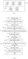
- An example of an image of a plurality of fingers provided by the TCM sensor 101 is represented by the Fig. 5A .
- the parts of the plurality of fingers in contact with the upper face of the transparent blade 100 appear in dark gray.
- the valleys of the fingerprints of the plurality of fingers appear in light gray or even white. Cast shadows appear near the fingers.
- Fig. 5B represents the image of the Fig. 5A after grayscale inversion. We realize that a simple inversion of the gray levels does not make it possible to obtain a usable image. Indeed, the shadows are still present and have only changed the level of gray. The presence of the drop shadows prevents each finger from being correctly identified and can create false fingerprint minutiae.
- the processing module 102 removes each continuous component from the first image in order to obtain a second image.
- a DC component in an image appears as a uniform area.
- the processing module 102 applies a high pass filter to the first image to obtain the second image.
- the second image is obtained by the processing module 102 by applying a top-hat filter as described in the document “ PT Jackway, improved morphological top-hat”, Electronics Letters, Vol: 36, Issue: 14, 6 July 2000 )” at the first frame to remove each DC component.
- Applying a top-hat filter to an initial image consists in applying a morphological closure to said initial image then in calculating a difference between the initial image and the image resulting from the morphological closure.
- Fig. 6A represents an image of a plurality of fingers supplied by a TCM sensor, referred to as the original image, used as input to a top-hat filter.
- Fig. 6B represents a result of applying a morphological closure to the original image.
- Fig. 6C represents a result of applying a top-hat filter to the original image.
- the pixels corresponding to the ridges of the fingerprints appear in dark gray while the pixels corresponding to the valleys appear in light gray, which corresponds to desired characteristics of the images.
- these interesting pixels are embedded among pixels offering little interest, or even no interest for fingerprint recognition. The remainder of the process makes it possible to eliminate pixels of no interest for fingerprint recognition.
- the processing module 102 obtains a third image by applying an averaging filter to the second image.
- An averaging filter replaces each pixel to be filtered by an average calculated from the value of said pixel and the values of neighboring pixels of said pixel.
- Fig. 7 represents an image corresponding to an application of an averaging filter to the image of the Fig. 6C ( ie in the second image).
- the processing module 102 applies a connected component analysis to the third image in order to define regions in said third image, each region consisting of pixels having an identical value, hereinafter called representative value.
- a related component analysis applied to an image consists of scanning the pixels of said image, and giving a label to each pixel. Two neighboring pixels that have the same value are considered to belong to the same region and therefore have the same label. Two neighboring pixels that do not have the same value do not belong to the same region and therefore have different labels.
- the processing module 102 organizes the regions obtained in the form of a hierarchical tree in which the regions are organized according to a parent-child relationship.
- a first region is a parent of a second region, which is then a child of the first region, when at least one pixel of the second region is close to a pixel of the first region and a difference between the values representative of the first and second regions is smaller than a deviation between the values representative of the first region and of all other regions having at least one pixel close to a pixel of the first region.
- the pixels corresponding to the zones of the plurality of fingers that are most pressed on the upper face of the transparent plate, that is to say corresponding in particular to the ridges of the fingerprints are the darkest pixels.
- a dark pixel corresponds to a low gray level value (ie close to "0") while a light pixel corresponds to a high gray level value ( ie close to "255" for 8-bit coded gray levels).
- a child region has a lower representative value (that is to say, the common value of each pixel constituting this region) than its parent region.
- the hierarchical tree therefore comprises leaves ( ie regions without children) corresponding to the darkest regions.
- the organization of the regions in the form of a hierarchical tree is based, for example, on a method described in the document " Yongchao Xu, Tree-based shape spaces: definition and applications in image processing and computer vision, Paris-Est University, 2013 ".
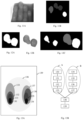
- Fig. 13A represents an image comprising a set of regions obtained by connected component analysis of a gray level image.
- the gray level of each region in the Fig. 13A corresponds to the representative value of said region.
- Regions 130 and 134 are the darkest regions and therefore associated with the lowest representative value.
- the region 139 which corresponds to the background of the image of the Fig. 13A is the lightest region and therefore associated with the highest representative value.
- Fig. 13B corresponds to a representation in the form of a hierarchical tree of the image of the Fig. 13A .
- the leaves of the tree consist of regions 130 and 134.
- the root of the tree consists of region 139.
- Leaf 130, nodes 131 to 133 and 138, and root 139 are arranged in order of increasing representative values .
- the leaf 134, the nodes 135 to 137 and 138 and the root 139 are organized in order of increasing representative values.
- the resulting hierarchical tree includes a branch A and a branch B.
- Agglomerating a child region with a parent region consists in determining an agglomerated region corresponding to a union of the parent and child regions.
- the processing module 102 traverses the hierarchical tree in order of increasing representative values and agglomerates a child region with its parent region when at least one predetermined criterion is respected.
- a first predetermined criterion is based on an evolution of an area of the regions resulting from the agglomeration. This criterion is based on the assumption that, when following the agglomeration of a child region with its parent region, the area of the agglomerated region has greatly increased compared to the area of the child region, then the agglomerated region encompasses several fingers.
- the processing module 102 calculates a percentage increase p of the area of the agglomerated region with respect to the area of the child region and compares this percentage increase p with a predetermined percentage increase P.
- a parent region is not agglomerated with a child region if the percentage increase p is greater than the predetermined percentage increase P.
- An agglomeration of a child region with its parent region is authorized when the increase coefficient C is less than or equal to a predetermined threshold CMAX. If the increase coefficient C is greater than the predetermined threshold CMAX, the agglomeration is not authorized and the child region is considered as a final region.
- the predetermined threshold CMAX is for example equal to “150”.
- the child region 130 can be agglomerated with its parent region 131 since the increase coefficient C is less than the predetermined threshold CMAX for this agglomeration. The region resulting from this agglomeration then becomes a child of region 132. For the same reason, agglomeration with regions 132 then 133 is authorized.
- the increase coefficient C being greater than the predetermined threshold CMAX for the agglomeration with the region 138, this agglomeration is not authorized.
- the agglomeration for branch A of the hierarchical tree stops and the region resulting from the agglomerations of regions 130 to 133 becomes final.
- the final region for branch B results from the agglomerations of regions 134 to 137.
- processing module 102 uses the first and/or the second criterion.
- FIG. 8 represents a succession of images illustrating a formation of regions in the third image using the hierarchical tree.
- the representative values of the regions have been reversed.
- the brightest regions in the images of the Fig. 8 correspond to the darker areas in the third image and the darker regions correspond to the lighter areas in the third image.
- the background images of the Fig. 8 appears black.
- the pictures of the Fig. 8 read left to right and top to bottom.
- a first region appears in the first image of the succession. This region corresponds to the darkest area of the third image. Two other regions appear in the second image of the succession, then a fourth in the third image of the succession. These four regions correspond to the four fingers placed on the upper face of the transparent blade 100. Each region corresponds to the darkest zone of a finger.
- the darkest areas in the third image (and therefore the brightest regions in the images of the Fig. 8 ) corresponding to the finger parts most pressed on the upper face of the transparent blade 100, we realize that some fingers are more pressed than others on said upper face.
- the pictures of the Fig. 8 show that traversing the hierarchical tree and the agglomeration of the child regions with their child region makes it possible, as the agglomerations progress, to obtain regions corresponding to the fingers.
- three fingers are agglomerated in the same region located to the left of the last image. This region is to be excluded because it does not respect the predetermined criterion and in particular the first criterion.
- the processing module 102 then considers that the regions of the penultimate image of the succession agglomerated to form the region to be excluded are final regions.
- Hierarchical tree organization makes it possible to browse the branches of the hierarchical tree independently. Several regions can thus grow in parallel and independently. A region can continue to grow while another region is in the final region stage.
- Fig. 9 represents a succession of images representing an evolution of a region.
- the pictures of the Fig. 9 are read from left to right.
- Fig. 9 typically corresponds to the traversal of one of the branches of the hierarchical tree. Thus, only one region grows in the images of the Fig. 9 .
- the region obtained in the penultimate image of the succession is a final region because the region obtained in the last image of the succession does not respect the predetermined criterion.
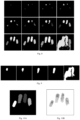
- FIG. 10A represents regions formed following traversal of the hierarchical tree. Four regions corresponding to the four fingers placed on the upper face of the transparent blade 100 have been obtained.
- Fig. 10B represents areas of the second image (i.e. the image resulting from the top-hat filter) corresponding to the four regions detected following the traversal of the hierarchical tree.
- the regions represented in the Fig. 10A are usable because they are disjoint, which makes it easy to distinguish the four fingers.
- Fig. 11A shows an image of a plurality of fingers provided by the TCM sensor 101 in which the fingers are glued and the Fig. 11B represents final regions obtained from this image.
- Fig. 11B represents final regions obtained from this image.
- Fig. 12A represents one of the regions detected in the image of the Fig. 11A and the Fig. 12B represents a fingerprint corresponding to the detected region.
- the region of the Fig. 12A matches two fingerprints. The application of the predetermined criterion therefore allowed the agglomeration of two regions which should not have been.
- the method of Fig. 4 includes an optional step 46 and step 47.
- the processing module 102 applies a morphological erosion to the regions obtained during step 45.
- the erosion is done by large filter in order to break up the regions obtained during step 45 if there is takes place.
- the processing module 102 applies at least one morphological dilation to the regions obtained during step 46 as long as each region obtained by morphological erosion remains independent. In other words, during step 47 the processing module 102 applies at least one morphological dilation to the regions obtained during step 46, as long as the regions obtained during step 46 do not merge.
- Fig. 12C represents on the left the region of the Fig. 12A after morphological erosion and, on the right, a result of at least one morphological dilation of the regions obtained by morphological erosion.
- the region of the Fig. 12A was separated into two distinct regions.
- a step 48 the processing module 102 determines a convex hull for each region obtained during step 45 (or during step 47 if this step has been executed). To do this, the processing module 102 uses a method described in " AM Andrew, Another efficient algorithm for convex hulls in two dimensions, Information Processing Letters, 1973 ".
- the processing module 102 generates a fourth image by keeping the pixels of the second image (ie the image resulting from the top-hat filter) situated in each convex envelope.
- the processing module 102 applies a processing to the values of the pixels of the fourth image comprised in each convex envelope so that these pixels have values lying within a range of predetermined values.
- the processing applied during step 50 consists, for each set of pixels located in a convex envelope, of a histogram enhancement in order to restore a dynamic of the pixel values of said set of pixels, to a dynamic of pixel values d fingerprint provided by a CCD or CMOS sensor.
- a histogram enhancement in order to restore a dynamic of the pixel values of said set of pixels, to a dynamic of pixel values d fingerprint provided by a CCD or CMOS sensor.
- the pixel values are distributed between "0" and "255", the pixels corresponding to the peaks being the darkest and the pixels corresponding to the valleys being the clearest.
- pixels whose value is between “0” and “100” are updated. “0” and pixels whose value is between “150” and “255” are set to “255”.
- Pixels whose value is between "100” and “150” are set to "0” if a majority of the pixels in their vicinity have a value between “0” and “100” and are set to "255” if a majority of the pixels in their neighborhood have a value between "150” and "255".
- a neighborhood of a pixel is for example a square of pixels with sides of three pixels centered on said pixel.
Landscapes
- Engineering & Computer Science (AREA)
- Physics & Mathematics (AREA)
- General Physics & Mathematics (AREA)
- Theoretical Computer Science (AREA)
- Computer Vision & Pattern Recognition (AREA)
- Multimedia (AREA)
- Human Computer Interaction (AREA)
- Image Input (AREA)
- Image Processing (AREA)
- Collating Specific Patterns (AREA)
Description
L'invention concerne un procédé de traitement d'une image représentative d'une pluralité de doigts fournie par un capteur d'images de type transistor en couches minces d'un système de capture d'empreintes digitales et un dispositif mettant en oeuvre le procédé.The invention relates to a method for processing an image representative of a plurality of fingers provided by a thin-film transistor type image sensor of a fingerprint capture system and a device implementing the method .
L'utilisation d'empreintes digitales, par exemple du type empreinte d'un doigt, d'une pluralité de doigts, d'une paume de main, permet de sécuriser des accès à des bâtiments ou à des machines. Utiliser cette technologie permet de renforcer la sécurité dans la mesure où la probabilité que deux personnes aient deux empreintes digitales identiques est quasiment nulle.The use of fingerprints, for example of the fingerprint type, of a plurality of fingers, of a palm of the hand, makes it possible to secure access to buildings or to machines. Using this technology makes it possible to reinforce security insofar as the probability that two people have two identical fingerprints is almost zero.
Un système de capture d'une empreinte digitale permet de capturer une image d'une empreinte digitale. Dans le cas d'une identification, cette empreinte est comparée avec un ensemble d'empreintes digitales de référence contenues dans une base de données. Dans le cas d'une authentification, cette empreinte est comparée à une seule empreinte digitale. La comparaison permet de déterminer si l'empreinte digitale capturée appartient ou non à une personne référencée dans la base de données ou si la personne est bien celle qu'elle prétend être.A fingerprint capture system captures an image of a fingerprint. In the case of an identification, this fingerprint is compared with a set of reference fingerprints contained in a database. In the case of authentication, this fingerprint is compared to a single fingerprint. The comparison makes it possible to determine whether or not the captured fingerprint belongs to a person referenced in the database or whether the person is indeed who he claims to be.
Un bon nombre de systèmes de capture d'empreintes digitales utilisent des capteurs d'images de type CCD (dispositif à transfert de charge, « charge-coupled device » en terminologie anglo-saxonne) ou CMOS (semiconducteur metal-oxyde complémentaires, « complementary metal-oxide-semiconductor » en terminologie anglo-saxonne). Les capteurs CCD et CMOS fournissent des images ayant des propriétés particulières (distributions des niveaux de gris ou des valeurs de composantes de couleurs, résolution, absences d'artéfacts, ...) que des algorithmes de traitement d'images, de reconnaissance ou de compression prennent en compte lors de leurs traitements. Ces traitements seraient en grande partie inadaptés s'ils devaient traiter des images présentant des propriétés différentes. Par exemple, ces algorithmes seraient incapables de traiter des images fournies par des capteurs utilisant une technologie différentes tels que les capteurs de type TCM (transistors en couches minces, « thin-film transistors (TFT) » en terminologie anglo-saxonne), dits capteurs TCM. Par exemple, lorsqu'un doigt est posé sur un système de capture d'empreintes digitales utilisant un capteur TCM, dit système TCM, le doigt apparaît dans l'image fournie par ce capteur avec des niveaux de gris inversés par rapport à une image fournie par un système de capture d'empreintes digitales utilisant un capteur CCD ou CMOS, dit système CCD/CMOS. Par ailleurs, dans les images de doigt fournies par un système TCM, des ombres portées apparaissent au voisinage du doigt, ce qui n'est pas le cas avec un système CCD/CMOS. La demande de brevet
Il est souhaitable de pallier ces inconvénients de l'état de la technique. Il est notamment souhaitable de proposer un procédé et un dispositif qui permettent d'utiliser des capteurs TCM avec des algorithmes destinés à recevoir des images provenant de capteurs CCD ou CMOS. Par ailleurs, ce procédé doit être simple à mettre en oeuvre.It is desirable to overcome these disadvantages of the state of the art. It is in particular desirable to propose a method and a device which make it possible to use TCM sensors with algorithms intended to receive images originating from CCD or CMOS sensors. Furthermore, this method must be simple to implement.
Selon un premier aspect de l'invention, l'invention concerne un procédé de traitement d'une image représentative d'au moins un doigt fournie par un capteur d'images de type transistor en couches minces d'un système de capture d'empreintes digitales, pour une identification ou une authentification de l'empreinte, ledit système comprenant une lame transparente comprenant une face sur laquelle est posé chaque doigt et ledit capteur d'images est positionné de sorte à générer une image de chaque doigt. Le procédé comprend :
- obtenir une image de chaque doigt fournie par le capteur d'images, dite première image ; obtenir une deuxième image en supprimant chaque composante continue de la première image en appliquant un filtre passe-haut;
- obtenir une troisième image en appliquant un filtre moyenneur à la deuxième image ;
- appliquer une analyse en composantes connexes à la troisième image afin de définir des régions dans ladite troisième image, chaque région comprenant des pixels ayant une valeur identique, dite valeur représentative ;
- organiser les régions sous forme d'arbre hiérarchique dans lequel les régions sont organisées selon une relation parents-enfants, une première région étant parent d'une deuxième région, qui est alors enfant de la première région, lorsqu'au moins un pixel de la deuxième région est voisin d'un pixel de la première région et qu'un écart entre les valeurs représentatives des première et deuxième régions est plus faible qu'un écart entre les valeurs représentatives de la première région et de toutes autres régions ayant au moins un pixel voisin d'un pixel de la première région, la région enfant ayant une valeur représentative plus faible que sa région parent;
- parcourir l'arbre hiérarchique par ordre de valeurs représentatives croissantes et agglomérer chaque région enfant avec sa région parent lorsqu'un coefficient d'accroissement C est inférieur à un premier seuil prédéterminé, le coefficient d'accroissement étant calculé de la manière suivante :

- où a et b sont des constantes prédéterminées, S est une aire de la région enfant et ΔS est un pourcentage d'augmentation de l'aire de la région agglomérée par rapport à l'aire de la région enfant ;
- déterminer une enveloppe convexe pour chaque région agglomérée obtenue ;
- générer une quatrième image en conservant les pixels situés dans chaque enveloppe convexe dans la deuxième image.
- obtain an image of each finger provided by the image sensor, called the first image; obtaining a second image by removing each DC component from the first image by applying a high pass filter;
- obtaining a third image by applying an averaging filter to the second image;
- applying a connected component analysis to the third image in order to define regions in said third image, each region comprising pixels having an identical value, called representative value;
- organize the regions in the form of a hierarchical tree in which the regions are organized according to a parent-child relationship, a first region being the parent of a second region, which is then a child of the first region, when at least one pixel of the second region is close to a pixel of the first region and that a difference between the values representative of the first and second regions is smaller than a difference between the values representative of the first region and of all other regions having at least one pixel neighboring a pixel of the first region, the child region having a lower representative value than its parent region;
- traverse the hierarchical tree in order of increasing representative values and agglomerate each child region with its parent region when an increase coefficient C is less than a first predetermined threshold, the increase coefficient being calculated in the following manner:
- where a and b are predetermined constants, S is an area of the child region and ΔS is a percentage increase in the area of the agglomerated region relative to the area of the child region;
- determining a convex hull for each agglomerated region obtained;
- generate a fourth image by keeping the pixels located in each convex hull in the second image.
L'image obtenue en appliquant le procédé de l'invention à une image issue d'un capteur de type transistor en couches minces possède alors des propriétés conformes aux propriétés d'images fournies par un capteur CCD ou CMOS. Les caractéristiques des images obtenues par ce procédé sont alors conformes à des caractéristiques d'images attendues par des procédés de traitement d'images adaptés à des images issues de capteurs CCD ou CMOS. Par ailleurs, l'organisation suivant un arbre hiérarchique et le parcours de cet arbre hiérarchique lors de la formation des régions, permet de déterminer plusieurs régions en parallèle et ainsi de traiter des images représentant une pluralité de doigts.The image obtained by applying the method of the invention to an image coming from a thin-film transistor type sensor then has properties that conform to the properties of images provided by a CCD or CMOS sensor. The characteristics of the images obtained by this method then conform to the characteristics of images expected by image processing methods adapted to images from CCD or CMOS sensors. Moreover, the organization according to a hierarchical tree and the course of this hierarchical tree during the formation of the regions, makes it possible to determine several regions in parallel and thus to process images representing a plurality of fingers.
Selon un mode de réalisation, le procédé comprend appliquer un traitement aux valeurs des pixels de la quatrième image compris dans chaque enveloppe convexe afin que ces pixels aient des valeurs se situant dans une gamme de valeurs prédéterminées.According to one embodiment, the method comprises applying a processing to the values of the pixels of the fourth image comprised in each convex envelope so that these pixels have values lying within a range of predetermined values.
Selon un mode de réalisation, le procédé comprend, fixer la valeur de chaque pixel de la quatrième image situé à l'extérieur d'une enveloppe convexe à une valeur prédéfinie et modifier une valeur initiale de chaque pixel de la quatrième image situé à l'intérieur d'une enveloppe convexe en une valeur finale en fonction d'une distance entre ledit pixel et ladite enveloppe convexe, de sorte que ladite valeur finale se rapproche de la valeur prédéfinie lorsque ladite distance diminue et se rapproche de la valeur initiale lorsque ladite distance augmente.According to one embodiment, the method comprises fixing the value of each pixel of the fourth image located outside a convex hull at a predefined value and modifying an initial value of each pixel of the fourth image located outside interior of a convex hull into a final value depending on a distance between said pixel and said convex hull, such that said final value approaches the predefined value when said distance decreases and approaches the initial value when said distance increase.
Selon un deuxième aspect de l'invention, l'invention concerne un dispositif de traitement d'une image représentative d'au moins un doigt fournie par un capteur d'images de type transistor en couches minces d'un système de capture d'empreintes digitales, pour une identification ou une authentification de l'empreinte, ledit système comprenant une lame transparente comprenant une face sur laquelle est posée chaque doigt et ledit capteur d'images est positionné de sorte à générer une image de chaque doigt. Le dispositif comprend :
- des moyens d'obtention pour obtenir une image de chaque doigt fournie par le capteur d'images, dite première image ;
- des moyens de filtrage passe-haut pour obtenir une deuxième image en supprimant chaque composante continue de la première image ;
- des moyens de filtrage pour obtenir une troisième image en appliquant un filtre moyenneur à la deuxième image ;
- des moyens de traitement pour appliquer une analyse en composantes connexes à la troisième image afin de définir des régions dans ladite troisième image, chaque région comprenant des pixels ayant une valeur identique, dite valeur représentative ;
- des moyens de traitement pour organiser les régions sous forme d'arbre hiérarchique dans lequel les régions sont organisées selon une relation parents-enfants, une première région étant parent d'une deuxième région, qui est alors enfant de la première région, lorsqu'au moins un pixel de la deuxième région est voisin d'un pixel de la première région et qu'un écart entre les valeurs représentatives des première et deuxième régions est plus faible qu'un écart entre les valeurs représentatives de la première région et de toutes autres régions ayant au moins un pixel voisin d'un pixel de la première région, la région enfant ayant une valeur représentative plus faible que sa région parent;
- des moyens de traitement pour parcourir l'arbre hiérarchique par ordre de valeurs représentatives croissantes et agglomérer chaque région enfant avec sa région parent lorsqu'un coefficient d'accroissement C est inférieur à un premier seuil prédéterminé, le coefficient d'accroissement étant calculé de la manière suivante :

- où a et b sont des constantes prédéterminées, S est une aire de la région enfant et ΔS est un pourcentage d'augmentation de l'aire de la région agglomérée par rapport à l'aire de la région enfant ;
- des moyens de traitement pour déterminer une enveloppe convexe pour chaque région agglomérée obtenue;
- des moyens de traitement pour générer une quatrième image en conservant les pixels situés dans chaque enveloppe convexe dans la deuxième image.
- obtaining means for obtaining an image of each finger supplied by the image sensor, referred to as the first image;
- high-pass filter means for obtaining a second image by removing each DC component from the first image;
- filter means for obtaining a third image by applying an averaging filter to the second image;
- processing means for applying a connected component analysis to the third image in order to define regions in said third image, each region comprising pixels having an identical value, called representative value;
- processing means for organizing the regions in the form of a hierarchical tree in which the regions are organized according to a parent-child relationship, a first region being a parent of a second region, which is then a child of the first region, when at at least one pixel of the second region is close to a pixel of the first region and that a difference between the values representative of the first and second regions is smaller than a difference between the values representative of the first region and of any other regions having at least one pixel neighboring a pixel of the first region, the child region having a lower representative value than its parent region;
- processing means for traversing the hierarchical tree in order of increasing representative values and agglomerating each child region with its parent region when an increase coefficient C is less than a first predetermined threshold, the increase coefficient being calculated from the following way:
- where a and b are predetermined constants, S is an area of the child region and ΔS is a percentage increase in the area of the agglomerated region relative to the area of the child region;
- processing means for determining a convex hull for each agglomerated region obtained;
- processing means for generating a fourth image by keeping the pixels located in each convex hull in the second image.
Selon un troisième aspect de l'invention, l'invention concerne un programme d'ordinateur comprenant des instructions pour mettre en oeuvre, par un dispositif, le procédé selon le premier aspect, lorsque ledit programme est exécuté par un processeur dudit dispositif.According to a third aspect of the invention, the invention relates to a computer program comprising instructions for implementing, by a device, the method according to the first aspect, when said program is executed by a processor of said device.
Selon un quatrième aspect de l'invention, l'invention concerne des moyens de stockage, stockant un programme d'ordinateur comprenant des instructions pour mettre en oeuvre, par un dispositif, le procédé selon le premier aspect, lorsque ledit programme est exécuté par un processeur dudit dispositif.According to a fourth aspect of the invention, the invention relates to storage means, storing a computer program comprising instructions for implementing, by a device, the method according to the first aspect, when said program is executed by a processor of said device.
Les caractéristiques de l'invention mentionnées ci-dessus, ainsi que d'autres, apparaîtront plus clairement à la lecture de la description suivante d'un exemple de réalisation, ladite description étant faite en relation avec les dessins joints, parmi lesquels :
- la
Fig. 1 décrit schématiquement un exemple de système de capture d'empreintes digitales utilisant le procédé selon l'invention ; - la
Fig. 2 illustre schématiquement de manière détaillée le système de capture d'empreintes digitales ; - la
Fig. 3 illustre schématiquement un exemple d'architecture matérielle d'un module de traitement mettant en oeuvre le procédé selon l'invention ; - la
Fig. 4 illustre schématiquement un exemple de procédé de traitement d'une image représentative d'au moins un doigt fournie par un capteur d'images de type transistor en couches minces; - la
Fig. 5A représente une image d'une pluralité de doigts fournie par un capteur d'images de type transistor en couches minces ; - la
Fig. 5A représente l'image d'une pluralité de doigts fournie par le capteur d'images de type transistor en couches minces après inversion des niveaux de gris ; - la
Fig. 6A représente une image d'une pluralité de doigts fournie par un capteur d'images de type transistor en couches minces utilisée en entrée d'un filtre top-hat ; - la
Fig. 6B représente l'image d'une pluralité de doigts fournie par le capteur d'images de type transistor en couches minces ayant subi une fermeture morphologique ; - la
Fig. 6C représente une image résultant d'un filtre top-hat ; - la
Fig. 7 représente l'image résultant du filtre top-hat après application d'un filtre moyenneur ; - La
Fig. 8 représente une succession d'images illustrant un procédé de formation de régions dans l'image résultant du filtre moyenneur en utilisant un arbre hiérarchique; - la
Fig. 9 représente une succession d'images représentant une évolution d'une région; - la
Fig. 10A représente un résultat du procédé de formation de régions; - la
Fig. 10B représente des zones de l'image résultant du filtre top-hat correspondant à des régions détectées par le procédé de formation de régions; - la
Fig. 11A représente une image d'une pluralité de doigts fournie par un capteur d'images de type transistor en couches minces dans laquelle les doigts sont collés ; - la
Fig. 11B représente des régions détectées dans l'image d'une pluralité de doigts dans laquelle les doigts sont collés ; - la
Fig. 12A représente une région détectée dans l'image d'une pluralité de doigts dans laquelle les doigts sont collés et laFig. 12B représente une empreinte correspondant à la région détectée ; - la
Fig. 12C représente à gauche une région détectée dans l'image d'une pluralité de doigts dans laquelle les doigts sont collés après érosion morphologique ; et, à droite, un résultat d'une dilatation morphologique des régions obtenues par érosion morphologique.
- there
Fig. 1 schematically describes an example of a fingerprint capture system using the method according to the invention; - there
Fig. 2 schematically illustrates in detail the fingerprint capture system; - there
Fig. 3 schematically illustrates an example of hardware architecture of a processing module implementing the method according to the invention; - there
Fig. 4 schematically illustrates an example of a process for processing an image representative of at least one finger supplied by a thin-film transistor type image sensor; - there
Fig. 5A represents an image of a plurality of fingers supplied by a thin film transistor type image sensor; - there
Fig. 5A represents the image of a plurality of fingers supplied by the thin film transistor type image sensor after inversion of the gray levels; - there
Fig. 6A represents an image of a plurality of fingers provided by a thin film transistor type image sensor used as input to a top-hat filter; - there
Fig. 6B represents the image of a plurality of fingers provided by the thin film transistor type image sensor having undergone a morphological closure; - there
Fig. 6C represents an image resulting from a top-hat filter; - there
Fig. 7 represents the image resulting from the top-hat filter after applying an averaging filter; - There
Fig. 8 represents a succession of images illustrating a method of forming regions in the image resulting from the averaging filter using a hierarchical tree; - there
Fig. 9 represents a succession of images representing an evolution of a region; - there
Fig. 10A represents a result of the region forming process; - there
Fig. 10B represents areas of the image resulting from the top-hat filter corresponding to regions detected by the method of forming regions; - there
Fig. 11A represents an image of a plurality of fingers provided by a thin film transistor type image sensor in which the fingers are glued; - there
Fig. 11B represents detected regions in the image of a plurality of fingers in which the fingers are stuck; - there
Fig. 12A represents a detected region in the image of a plurality of fingers in which the fingers are stuck and theFig. 12B represents a fingerprint corresponding to the detected region; - there
Fig. 12C represents on the left a region detected in the image of a plurality of fingers in which the fingers are glued after morphological erosion; and, on the right, a result of a morphological dilation of the regions obtained by morphological erosion.
Le procédé de l'invention est décrit dans un contexte où un système de capture d'empreintes digitales utilisant un capteur de type transistor en couches minces fait des acquisitions d'images d'une pluralité de doigts. L'invention est toutefois adaptée pour fonctionner sur des images ne comportant qu'un doigt. Il permet alors d'obtenir des images d'un doigt présentant des propriétés identiques aux propriétés d'images acquises par un système de capture d'empreintes digitales utilisant un capteur CCD ou CMOS.The method of the invention is described in a context where a fingerprint capture system using a thin film transistor type sensor acquires images of a plurality of fingers. The invention is however adapted to operate on images comprising only one finger. It then makes it possible to obtain images of a finger having properties identical to the properties of images acquired by a fingerprint capture system using a CCD or CMOS sensor.
La
Dans la
La
Le système de capture d'empreintes digitales 10 comprend une lame transparente 100 comprenant une face supérieure sur laquelle est posée la pluralité de doigts, dont seul un doigt D est représenté dans la
La
Selon l'exemple d'architecture matérielle représenté à la
Le processeur 1021 est capable d'exécuter des instructions chargées dans la RAM 1022 à partir de la ROM 1023, d'une mémoire externe (non représentée), d'un support de stockage (tel qu'une carte SD), ou d'un réseau de communication. Lorsque le module de traitement 102 est mis sous tension, le processeur 1021 est capable de lire de la RAM 1022 des instructions et de les exécuter. Ces instructions forment un programme d'ordinateur causant la mise en oeuvre, par le processeur 1021, du procédé décrit en relation avec la
Le procédé décrit en relation avec la
La
Dans une étape 40, le module de traitement 102 obtient une première image du capteur TCM 101. Un exemple d'une image d'une pluralité de doigts fournie par le capteur TCM 101 est représenté par la
Dans une étape 41, le module de traitement 102 supprime chaque composante continue de la première image afin d'obtenir une deuxième image. Une composante continue dans une image apparaît sous forme d'une zone uniforme. Dans un mode de réalisation, le module de traitement 102 applique un filtre passe haut à la première image pour obtenir la deuxième image. Dans un mode de réalisation, la deuxième image est obtenue par le module de traitement 102 en appliquant un filtre top-hat tel que décrit dans le document «
Dans une étape 42, le module de traitement 102 obtient une troisième image en appliquant un filtre moyenneur à la deuxième image. Un filtre moyenneur remplace chaque pixel à filtrer par une moyenne calculée à partir de la valeur dudit pixel et des valeurs de pixels voisins dudit pixel. La
Dans une étape 43, le module de traitement 102 applique une analyse en composantes connexes à la troisième image afin de définir des régions dans ladite troisième image, chaque région étant constituée de pixels ayant une valeur identique, appelée par la suite valeur représentative. Une analyse en composante connexe appliquée à une image consiste à parcourir les pixels de ladite image, et à donner un label à chaque pixel. Deux pixels voisins qui ont la même valeur sont considérés comme appartenant à une même région et ont donc le même label. Deux pixels voisins qui n'ont pas la même valeur n'appartiennent pas à la même région et ont donc des labels différents.In a
Dans une étape 44, le module de traitement 102 organise les régions obtenues sous forme d'arbre hiérarchique dans lequel les régions sont organisées selon une relation parents-enfants. Dans cet arbre, une première région est parent d'une deuxième région, qui est alors enfant de la première région, lorsqu'au moins un pixel de la deuxième région est voisin d'un pixel de la première région et qu'un écart entre les valeurs représentatives des première et deuxième régions est plus faible qu'un écart entre les valeurs représentatives de la première région et de toutes autres régions ayant au moins un pixel voisin d'un pixel de la première région. Dans la deuxième image, les pixels correspondant aux zones de la pluralité de doigts les plus appuyés sur la face supérieure de la lame transparente, c'est-à-dire correspondant notamment aux crêtes des empreintes digitales sont les pixels les plus foncés. En termes de niveau de gris, un pixel foncé correspond à une valeur de niveau de gris faible (i.e. proche de « 0 ») alors qu'un pixel clair correspond à une valeur de niveau de gris élevée (i.e. proche de « 255 » pour des niveaux de gris codés sur « 8 » bits). Dans l'arbre hiérarchique, une région enfant possède une valeur représentative (c'est-à-dire, la valeur commune de chaque pixel constituant cette région) plus faible que sa région parent. L'arbre hiérarchique comprend donc des feuilles (i.e. des régions sans enfants) correspondant aux régions les plus foncées. L'organisation des régions sous forme d'arbre hiérarchique s'appuie par exemple sur une méthode décrite dans le document «
La
La
On note que, lorsqu'une intersection entre une région enfant et une région parent est non vide, l'intersection est considérée comme faisant partie de la région enfant, mais ne fait pas partie de la région parent. Ainsi la région 130 qui est totalement incluse dans la région 131, ne fait pas partie de la région 131. Agglomérer une région enfant avec une région parent consiste à déterminer une région agglomérée correspondant à une union des régions parent et enfant.Note that when an intersection between a child region and a parent region is non-empty, the intersection is considered part of the child region, but is not part of the parent region. Thus
Dans une étape 46, le module de traitement 102 parcourt l'arbre hiérarchique par ordre de valeurs représentatives croissantes et agglomère une région enfant avec sa région parent lorsqu'au moins un critère prédéterminé est respecté. Un premier critère prédéterminé est basé sur une évolution d'une aire des régions résultant de l'agglomération. Ce critère est basé sur l'hypothèse que, lorsque suite à l'agglomération d'une région enfant avec sa région parent, l'aire de la région agglomérée a très fortement augmenté par rapport à l'aire de la région enfant, alors la région agglomérée englobe plusieurs doigts.In a
Le module de traitement 102 calcule un pourcentage d'augmentation p de l'aire de la région agglomérée par rapport à l'aire de la région enfant et compare ce pourcentage d'augmentation p avec un pourcentage d'augmentation prédéterminé P. Une région parent n'est pas agglomérée avec une région enfant si le pourcentage d'augmentation p est supérieur au pourcentage d'augmentation prédéterminé P.The
Le module de traitement 102 calcule un coefficient d'accroissement C : ![]()
![]()
Une agglomération d'une région enfant avec sa région parent est autorisée lorsque le coefficient d'accroissement C est inférieur ou égal à un seuil prédéterminé CMAX. Si le coefficient d'accroissement C est supérieur au seuil prédéterminé CMAX, l'agglomération n'est pas autorisée et la région enfant est considérée comme une région finale. Le seuil prédéterminé CMAX est par exemple égal à « 150 ». Dans l'exemple de la
On note que le module de traitement 102 utilise le premier et/ou le deuxième critère.It is noted that the
La
Pour plus de visibilité, dans les images de la
Les images de la
Les images de la
On remarque que l'organisation en arbre hiérarchique permet de parcourir les branches de l'arbre hiérarchique indépendamment. Plusieurs régions peuvent ainsi grossir en parallèle et indépendamment. Une région peut continuer de grossir alors qu'une autre région est au stade de région finale.Note that the hierarchical tree organization makes it possible to browse the branches of the hierarchical tree independently. Several regions can thus grow in parallel and independently. A region can continue to grow while another region is in the final region stage.
La
La
La
Le résultat du parcours de l'arbre hiérarchique n'est cependant pas toujours aussi idéal.However, the result of traversing the hierarchical tree is not always so ideal.
La
La
Pour traiter ce cas, le procédé de la
Lors de l'étape 46, le module de traitement 102 applique une érosion morphologique aux régions obtenues lors de l'étape 45. L'érosion se fait par large filtre afin de morceler les régions obtenues lors de l'étape 45 s'il y a lieu.During
Lors de l'étape 47, le module de traitement 102 applique au moins une dilatation morphologique aux régions obtenues lors de l'étape 46 tant que chaque région obtenue par érosion morphologique reste indépendante. En d'autres termes, lors de l'étape 47 le module de traitement 102 applique au moins une dilatation morphologique aux régions obtenues lors de l'étape 46, tant que les régions obtenues lors de l'étape 46 ne fusionnent pas.During
La
Dans une étape 48, le module de traitement 102 détermine une enveloppe convexe pour chaque région obtenue lors de l'étape 45 (ou lors de l'étape 47 si cette étape a été exécutée). Pour ce faire, le module de traitement 102 utilise une méthode décrite dans «
Dans une étape 49, le module de traitement 102 génère une quatrième image en conservant les pixels de la deuxième image (i.e. l'image issue du filtre top-hat) situés dans chaque enveloppe convexe.In a
Dans une étape 50 optionnelle, le module de traitement 102 applique un traitement aux valeurs des pixels de la quatrième image compris dans chaque enveloppe convexe afin que ces pixels aient des valeurs se situant dans une gamme de valeurs prédéterminées. Le traitement appliqué lors de l'étape 50 consiste, pour chaque ensemble de pixels situés dans une enveloppe convexe, en un rehaussement d'histogramme afin de remettre une dynamique des valeurs de pixels dudit ensemble de pixels, sur une dynamique de valeurs de pixels d'empreintes digitales fournie par un capteur CCD ou CMOS. Dans une image en niveaux de gris sur « 8 » bits fournie par un capteur CCD ou CMOS, les valeurs des pixels sont réparties entre « 0 » et « 255 », les pixels correspondant aux crêtes étant les plus foncés et les pixels correspondant aux vallées étant les plus clairs. Dans un mode de réalisation, le traitement appliqué lors de l'étape 50 consiste à étendre l'histogramme des valeurs des pixels de la quatrième image compris dans chaque enveloppe convexe de manière à le répartir entre « 0 » et « 255 ». Si par exemple, les valeurs desdits pixels sont comprises entre une valeur minimale VMIN et une valeur maximale VMAX, chaque pixel ayant la valeur VMIN prend la valeur « 0 », chaque pixel ayant la valeur VMAX prend la valeur « 255 » et chaque pixel ayant une valeur VINT intermédiaire entre VMIN et VMAX prend une valeur ![]()
![]()
Dans un autre mode de réalisation, toujours pour une image en niveaux de gris sur « 8 » bits, les pixels dont la valeur est comprise entre « 0 » et « 100 » sont mis à « 0 » et les pixels dont la valeur est comprise entre « 150 » et « 255 » sont mis à « 255 ».In another embodiment, still for an "8"-bit grayscale image, the pixels whose value is between "0" and "100" are updated. “0” and pixels whose value is between “150” and “255” are set to “255”.
Les pixels dont la valeur est comprise entre « 100 » et « 150 » sont mis à « 0 » si une majorité des pixels de leur voisinage ont une valeur comprise entre « 0 » et « 100 » et sont mis à « 255 » si une majorité des pixels de leur voisinage ont une valeur comprise entre « 150 » et « 255 ». Un voisinage d'un pixel est par exemple un carré de pixels de trois pixels de côté centré sur ledit pixel.Pixels whose value is between "100" and "150" are set to "0" if a majority of the pixels in their vicinity have a value between "0" and "100" and are set to "255" if a majority of the pixels in their neighborhood have a value between "150" and "255". A neighborhood of a pixel is for example a square of pixels with sides of three pixels centered on said pixel.
Dans une étape 51 optionnelle, le module de traitement 102 applique une transformée en distance (TFD) aux pixels de la quatrième image compris dans chaque enveloppe convexe obtenus après le traitement de l'étape 50. Par la suite, nous appelons ces pixels pixels internes. On considère ici que les pixels de l'enveloppe convexe sont des pixels internes. Le principe de la TFD est décrit dans le document «
- Si dTFD > DIST, la valeur du pixel interne reste inchangée.
- Si 0 ≤ dTFD ≤ DIST, la valeur du pixel Vpixel est modifiée de la manière suivante :

- If d TFD > DIST, the value of the internal pixel remains unchanged.
- If 0 ≤ d TFD ≤ DIST, the value of pixel V pixel is modified as follows:
Claims (6)
- Method for processing an image representative of at least one finger, said image being delivered by a thin-film-transistor image sensor of a fingerprint-capturing system (10), with a view to identification or authentication of the print, said system comprising a transparent plate (100) comprising a face on which is placed each finger and said image sensor (101) being positioned so as to generate an image of each finger, the method comprising:obtaining (40) an image of each finger, said image being delivered by the image sensor, said image being referred to as the first image;obtaining (41) a second image by removing each and every continuous component from the first image by applying a high-pass filter;obtaining (42) a third image by applying an averaging filter to the second image;applying (43) connected-component analysis to the third image in order to define regions in said third image, each region comprising pixels having an identical value, referred to as the representative value;organizing (44) the regions into a hierarchical tree in which the regions are organized according to a parent-child relationship, a first region being a parent of a second region, which is then a child of the first region, when at least one pixel of the second region neighbours a pixel of the first region and when a deviation between the representative values of the first and second regions is smaller than a deviation between the representative values of the first region and of all other regions having at least one pixel neighbouring a pixel of the first region, the child region having a representative value lower than its parent region;traversing (45) the hierarchical tree in increasing order of representative values and clustering each child region with its parent region when a growth coefficient C is lower than a first predetermined threshold, the growth coefficient being computed in the following way:
 where a and b are predetermined constants, S is an area of the child region and ΔS is a percentage increase in the area of the clustered region with respect to the area of the child region;determining (48) a convex hull for each obtained clustered region;generating (49) a fourth image by preserving pixels located in each convex hull in the second image.
 - Method according to Claim 1, characterized in that the method comprises applying (50) processing to the values of the pixels of the fourth image comprised in each convex hull in order to make it so that these pixels have values located in a range of predetermined values.
- Method according to either one of the preceding claims, characterized in that the method comprises setting the value of each pixel of the fourth image located outside a convex hull to a predefined value and modifying an initial value of each pixel of the fourth image located inside a convex hull to a final value depending on a distance between said pixel and said convex hull, in such a way that the final value approaches the predefined value as said distance decreases and approaches the initial value as said distance increases.
- Device for processing an image representative of at least one finger, said image being delivered by a thin-film-transistor image sensor of a fingerprint-capturing system (10), with a view to identification or authentication of the print, said system comprising a transparent plate (100) comprising a face on which is placed each finger and said image sensor (101) being positioned so as to generate an image of each finger, the device comprising:obtaining means for obtaining (40) an image of each finger, said image being delivered by the image sensor, said image being referred to as the first image;high-pass filtering means for obtaining (41) a second image by removing each and every continuous component from the first image;filtering means for obtaining (42) a third image by applying an averaging filter to the second image;processing means for applying (43) connected-component analysis to the third image in order to define regions in said third image, each region comprising pixels having an identical value, referred to as the representative value;processing means for organizing (44) the regions into a hierarchical tree in which the regions are organized according to a parent-child relationship, a first region being a parent of a second region, which is then a child of the first region, when at least one pixel of the second region neighbours a pixel of the first region and when a deviation between the representative values of the first and second regions is smaller than a deviation between the representative values of the first region and of all other regions having at least one pixel neighbouring a pixel of the first region, the child region having a representative value lower than its parent region;processing means for traversing (45) the hierarchical tree in increasing order of representative values and clustering each child region with its parent region when a growth coefficient C is lower than a first predetermined threshold, the growth coefficient being computed in the following way:
 where a and b are predetermined constants, S is an area of the child region and ΔS is a percentage increase in the area of the clustered region with respect to the area of the child region;processing means for determining (48) a convex hull for each obtained clustered region;processing means for generating (49) a fourth image by preserving pixels located in each convex hull in the second image.
 - Computer program, characterized in that it comprises instructions for implementing, by means of a device (102), the method according to any one of Claims 1 to 3, when said program is executed by a processor (1021) of said device.
- Storage means, characterized in that they store a computer program comprising instructions for implementing, by means of a device (102), the method according to any one of Claims 1 to 3, when said program is executed by a processor (1021) of said device.
Applications Claiming Priority (1)
| Application Number | Priority Date | Filing Date | Title |
|---|---|---|---|
| FR1857447A FR3084944B1 (en) | 2018-08-10 | 2018-08-10 | IMPRESSION IMAGE PROCESSING PROCESS |
Publications (3)
| Publication Number | Publication Date |
|---|---|
| EP3608835A1 EP3608835A1 (en) | 2020-02-12 |
| EP3608835C0 EP3608835C0 (en) | 2023-07-12 |
| EP3608835B1 true EP3608835B1 (en) | 2023-07-12 |
Family
ID=65494229
Family Applications (1)
| Application Number | Title | Priority Date | Filing Date |
|---|---|---|---|
| EP19189722.2A Active EP3608835B1 (en) | 2018-08-10 | 2019-08-02 | Method for processing images of fingerprints |
Country Status (3)
| Country | Link |
|---|---|
| US (1) | US10896312B2 (en) |
| EP (1) | EP3608835B1 (en) |
| FR (1) | FR3084944B1 (en) |
Families Citing this family (3)
| Publication number | Priority date | Publication date | Assignee | Title |
|---|---|---|---|---|
| ATE548971T1 (en) | 2004-07-13 | 2012-03-15 | Dexcom Inc | TRANSCUTANEOUS ANALYTICAL SENSOR |
| CN109086769B (en) * | 2018-07-19 | 2021-11-02 | 武汉科技大学 | A method for identifying digital strings of fracture adhesion laser printing |
| CA3210177A1 (en) | 2021-03-19 | 2022-09-22 | Dexcom, Inc. | Drug releasing membrane for analyte sensor |
Citations (1)
| Publication number | Priority date | Publication date | Assignee | Title |
|---|---|---|---|---|
| EP3214601B1 (en) * | 2016-03-04 | 2020-10-07 | Idemia Identity & Security France | Image enhancement method applicable to fingerprint images |
-
2018
- 2018-08-10 FR FR1857447A patent/FR3084944B1/en active Active
-
2019
- 2019-07-31 US US16/527,957 patent/US10896312B2/en active Active
- 2019-08-02 EP EP19189722.2A patent/EP3608835B1/en active Active
Patent Citations (1)
| Publication number | Priority date | Publication date | Assignee | Title |
|---|---|---|---|---|
| EP3214601B1 (en) * | 2016-03-04 | 2020-10-07 | Idemia Identity & Security France | Image enhancement method applicable to fingerprint images |
Also Published As
| Publication number | Publication date |
|---|---|
| FR3084944A1 (en) | 2020-02-14 |
| EP3608835A1 (en) | 2020-02-12 |
| US20200050827A1 (en) | 2020-02-13 |
| EP3608835C0 (en) | 2023-07-12 |
| FR3084944B1 (en) | 2021-05-07 |
| US10896312B2 (en) | 2021-01-19 |
Similar Documents
| Publication | Publication Date | Title |
|---|---|---|
| BE1017547A6 (en) | COMPRESSION OF DIGITAL IMAGES OF SCANNED DOCUMENTS. | |
| FR3087558A1 (en) | METHOD FOR EXTRACTING CHARACTERISTICS OF A FINGERPRINT REPRESENTED BY AN INPUT IMAGE | |
| EP3608835B1 (en) | Method for processing images of fingerprints | |
| FR2901898A1 (en) | IDENTIFICATION METHOD AND ACQUIRING DEVICE FOR CARRYING OUT SAID METHOD | |
| CA3043090C (en) | Character recognition process | |
| WO2013098512A1 (en) | Method and device for detecting and quantifying cutaneous signs on an area of skin | |
| EP3620970A1 (en) | Method for extracting characteristics of a fingerprint represented by an input image | |
| FR3102600A1 (en) | Method of segmenting an input image representing at least one biometric fingerprint using a convolutional neural network | |
| FR2905188A1 (en) | Input image e.g. palm imprint image, density converting method for e.g. image processing improving system, involves converting minimum local and maximum local values into minimum and maximum common values, and reconstructing input image | |
| EP3214601B1 (en) | Image enhancement method applicable to fingerprint images | |
| FR3053500A1 (en) | METHOD FOR DETECTING FRAUD OF AN IRIS RECOGNITION SYSTEM | |
| EP4016381A1 (en) | Method for extracting a signature from a fingerprint and device implementing said method | |
| EP3929809A1 (en) | Method of detection of at least one visible biometric trait on an input image by means of a convolutional neural network | |
| FR2795205A1 (en) | METHOD FOR BINARIZING DIGITAL IMAGES WITH MULTIPLE GRAY LEVELS | |
| WO2013034654A1 (en) | Identification by iris recognition | |
| FR3088755A1 (en) | METHOD FOR UNFLOUTING AN IMAGE | |
| EP4099200A1 (en) | Method and device for biometric identification and/or authentication | |
| EP0447306B1 (en) | Device for recognising sequences in a multidimensional signal | |
| EP3825915A1 (en) | Classification of a biometric print wherein an image is input | |
| WO2007077175A1 (en) | Method for classifying images by neuronal networks and a classifier of pre-learned images, corresponding device and computer program | |
| WO2020144225A1 (en) | Method for processing digital images | |
| FR2861524A1 (en) | Method for detecting orientation of image taken by digital camera, involves detecting lines in image, calculating attributes that characterize lines, for each detected line, and detecting orientation of image according to attributes | |
| FR2899359A1 (en) | METHOD USING MULTI-RESOLUTION OF IMAGES FOR OPTICAL RECOGNITION OF POSTAL SHIPMENTS | |
| FR3089662A1 (en) | Method for recognizing objects such as traffic signs by means of an on-board camera in a motor vehicle | |
| FR3157636A1 (en) | Method and device for determining fraud in a biometric image recognition system. |
Legal Events
| Date | Code | Title | Description |
|---|---|---|---|
| PUAI | Public reference made under article 153(3) epc to a published international application that has entered the european phase |
Free format text: ORIGINAL CODE: 0009012 |
|
| STAA | Information on the status of an ep patent application or granted ep patent |
Free format text: STATUS: REQUEST FOR EXAMINATION WAS MADE |
|
| 17P | Request for examination filed |
Effective date: 20190806 |
|
| AK | Designated contracting states |
Kind code of ref document: A1 Designated state(s): AL AT BE BG CH CY CZ DE DK EE ES FI FR GB GR HR HU IE IS IT LI LT LU LV MC MK MT NL NO PL PT RO RS SE SI SK SM TR |
|
| AX | Request for extension of the european patent |
Extension state: BA ME |
|
| STAA | Information on the status of an ep patent application or granted ep patent |
Free format text: STATUS: EXAMINATION IS IN PROGRESS |
|
| 17Q | First examination report despatched |
Effective date: 20210226 |
|
| REG | Reference to a national code |
Ref country code: DE Ipc: G06T0007110000 Ref country code: DE Ref legal event code: R079 Ref document number: 602019032433 Country of ref document: DE Free format text: PREVIOUS MAIN CLASS: G06K0009000000 Ipc: G06T0007110000 |
|
| GRAP | Despatch of communication of intention to grant a patent |
Free format text: ORIGINAL CODE: EPIDOSNIGR1 |
|
| STAA | Information on the status of an ep patent application or granted ep patent |
Free format text: STATUS: GRANT OF PATENT IS INTENDED |
|
| RIC1 | Information provided on ipc code assigned before grant |
Ipc: G06V 10/26 20220101ALI20230314BHEP Ipc: G06T 7/194 20170101ALI20230314BHEP Ipc: G06T 7/155 20170101ALI20230314BHEP Ipc: G06T 7/11 20170101AFI20230314BHEP Ipc: G06T 7/187 20170101ALI20230314BHEP Ipc: G06V 40/12 20220101ALI20230314BHEP Ipc: G06V 10/52 20220101ALI20230314BHEP |
|
| INTG | Intention to grant announced |
Effective date: 20230329 |
|
| GRAS | Grant fee paid |
Free format text: ORIGINAL CODE: EPIDOSNIGR3 |
|
| GRAA | (expected) grant |
Free format text: ORIGINAL CODE: 0009210 |
|
| STAA | Information on the status of an ep patent application or granted ep patent |
Free format text: STATUS: THE PATENT HAS BEEN GRANTED |
|
| AK | Designated contracting states |
Kind code of ref document: B1 Designated state(s): AL AT BE BG CH CY CZ DE DK EE ES FI FR GB GR HR HU IE IS IT LI LT LU LV MC MK MT NL NO PL PT RO RS SE SI SK SM TR |
|
| REG | Reference to a national code |
Ref country code: CH Ref legal event code: EP |
|
| REG | Reference to a national code |
Ref country code: IE Ref legal event code: FG4D Free format text: LANGUAGE OF EP DOCUMENT: FRENCH |
|
| REG | Reference to a national code |
Ref country code: DE Ref legal event code: R096 Ref document number: 602019032433 Country of ref document: DE |
|
| U01 | Request for unitary effect filed |
Effective date: 20230712 |
|
| U07 | Unitary effect registered |
Designated state(s): AT BE BG DE DK EE FI FR IT LT LU LV MT NL PT SE SI Effective date: 20230720 |
|
| U20 | Renewal fee for the european patent with unitary effect paid |
Year of fee payment: 5 Effective date: 20230816 |
|
| REG | Reference to a national code |
Ref country code: LT Ref legal event code: MG9D |
|
| PG25 | Lapsed in a contracting state [announced via postgrant information from national office to epo] |
Ref country code: GR Free format text: LAPSE BECAUSE OF FAILURE TO SUBMIT A TRANSLATION OF THE DESCRIPTION OR TO PAY THE FEE WITHIN THE PRESCRIBED TIME-LIMIT Effective date: 20231013 |
|
| PG25 | Lapsed in a contracting state [announced via postgrant information from national office to epo] |
Ref country code: ES Free format text: LAPSE BECAUSE OF FAILURE TO SUBMIT A TRANSLATION OF THE DESCRIPTION OR TO PAY THE FEE WITHIN THE PRESCRIBED TIME-LIMIT Effective date: 20230712 |
|
| PG25 | Lapsed in a contracting state [announced via postgrant information from national office to epo] |
Ref country code: IS Free format text: LAPSE BECAUSE OF FAILURE TO SUBMIT A TRANSLATION OF THE DESCRIPTION OR TO PAY THE FEE WITHIN THE PRESCRIBED TIME-LIMIT Effective date: 20231112 |
|
| PG25 | Lapsed in a contracting state [announced via postgrant information from national office to epo] |
Ref country code: RS Free format text: LAPSE BECAUSE OF FAILURE TO SUBMIT A TRANSLATION OF THE DESCRIPTION OR TO PAY THE FEE WITHIN THE PRESCRIBED TIME-LIMIT Effective date: 20230712 Ref country code: NO Free format text: LAPSE BECAUSE OF FAILURE TO SUBMIT A TRANSLATION OF THE DESCRIPTION OR TO PAY THE FEE WITHIN THE PRESCRIBED TIME-LIMIT Effective date: 20231012 Ref country code: IS Free format text: LAPSE BECAUSE OF FAILURE TO SUBMIT A TRANSLATION OF THE DESCRIPTION OR TO PAY THE FEE WITHIN THE PRESCRIBED TIME-LIMIT Effective date: 20231112 Ref country code: HR Free format text: LAPSE BECAUSE OF FAILURE TO SUBMIT A TRANSLATION OF THE DESCRIPTION OR TO PAY THE FEE WITHIN THE PRESCRIBED TIME-LIMIT Effective date: 20230712 Ref country code: GR Free format text: LAPSE BECAUSE OF FAILURE TO SUBMIT A TRANSLATION OF THE DESCRIPTION OR TO PAY THE FEE WITHIN THE PRESCRIBED TIME-LIMIT Effective date: 20231013 Ref country code: ES Free format text: LAPSE BECAUSE OF FAILURE TO SUBMIT A TRANSLATION OF THE DESCRIPTION OR TO PAY THE FEE WITHIN THE PRESCRIBED TIME-LIMIT Effective date: 20230712 |
|
| PG25 | Lapsed in a contracting state [announced via postgrant information from national office to epo] |
Ref country code: PL Free format text: LAPSE BECAUSE OF FAILURE TO SUBMIT A TRANSLATION OF THE DESCRIPTION OR TO PAY THE FEE WITHIN THE PRESCRIBED TIME-LIMIT Effective date: 20230712 |
|
| REG | Reference to a national code |
Ref country code: CH Ref legal event code: PL |
|
| REG | Reference to a national code |
Ref country code: DE Ref legal event code: R097 Ref document number: 602019032433 Country of ref document: DE |
|
| PG25 | Lapsed in a contracting state [announced via postgrant information from national office to epo] |
Ref country code: SM Free format text: LAPSE BECAUSE OF FAILURE TO SUBMIT A TRANSLATION OF THE DESCRIPTION OR TO PAY THE FEE WITHIN THE PRESCRIBED TIME-LIMIT Effective date: 20230712 Ref country code: RO Free format text: LAPSE BECAUSE OF FAILURE TO SUBMIT A TRANSLATION OF THE DESCRIPTION OR TO PAY THE FEE WITHIN THE PRESCRIBED TIME-LIMIT Effective date: 20230712 Ref country code: CZ Free format text: LAPSE BECAUSE OF FAILURE TO SUBMIT A TRANSLATION OF THE DESCRIPTION OR TO PAY THE FEE WITHIN THE PRESCRIBED TIME-LIMIT Effective date: 20230712 Ref country code: MC Free format text: LAPSE BECAUSE OF FAILURE TO SUBMIT A TRANSLATION OF THE DESCRIPTION OR TO PAY THE FEE WITHIN THE PRESCRIBED TIME-LIMIT Effective date: 20230712 Ref country code: SK Free format text: LAPSE BECAUSE OF FAILURE TO SUBMIT A TRANSLATION OF THE DESCRIPTION OR TO PAY THE FEE WITHIN THE PRESCRIBED TIME-LIMIT Effective date: 20230712 Ref country code: CH Free format text: LAPSE BECAUSE OF NON-PAYMENT OF DUE FEES Effective date: 20230831 |
|
| PLBE | No opposition filed within time limit |
Free format text: ORIGINAL CODE: 0009261 |
|
| STAA | Information on the status of an ep patent application or granted ep patent |
Free format text: STATUS: NO OPPOSITION FILED WITHIN TIME LIMIT |
|
| REG | Reference to a national code |
Ref country code: IE Ref legal event code: MM4A |
|
| 26N | No opposition filed |
Effective date: 20240415 |
|
| GBPC | Gb: european patent ceased through non-payment of renewal fee |
Effective date: 20231012 |
|
| PG25 | Lapsed in a contracting state [announced via postgrant information from national office to epo] |
Ref country code: IE Free format text: LAPSE BECAUSE OF NON-PAYMENT OF DUE FEES Effective date: 20230802 |
|
| PG25 | Lapsed in a contracting state [announced via postgrant information from national office to epo] |
Ref country code: GB Free format text: LAPSE BECAUSE OF NON-PAYMENT OF DUE FEES Effective date: 20231012 |
|
| PG25 | Lapsed in a contracting state [announced via postgrant information from national office to epo] |
Ref country code: IE Free format text: LAPSE BECAUSE OF NON-PAYMENT OF DUE FEES Effective date: 20230802 Ref country code: GB Free format text: LAPSE BECAUSE OF NON-PAYMENT OF DUE FEES Effective date: 20231012 |
|
| U20 | Renewal fee for the european patent with unitary effect paid |
Year of fee payment: 6 Effective date: 20240723 |
|
| U1K | Transfer of rights of the unitary patent after the registration of the unitary effect |
Owner name: IDEMIA PUBLIC SECURITY FRANCE; FR |
|
| U1N | Appointed representative for the unitary patent procedure changed after the registration of the unitary effect |
Representative=s name: IPS; FR |
|
| PG25 | Lapsed in a contracting state [announced via postgrant information from national office to epo] |
Ref country code: CY Free format text: LAPSE BECAUSE OF FAILURE TO SUBMIT A TRANSLATION OF THE DESCRIPTION OR TO PAY THE FEE WITHIN THE PRESCRIBED TIME-LIMIT; INVALID AB INITIO Effective date: 20190802 |
|
| PG25 | Lapsed in a contracting state [announced via postgrant information from national office to epo] |
Ref country code: HU Free format text: LAPSE BECAUSE OF FAILURE TO SUBMIT A TRANSLATION OF THE DESCRIPTION OR TO PAY THE FEE WITHIN THE PRESCRIBED TIME-LIMIT; INVALID AB INITIO Effective date: 20190802 |
|
| U20 | Renewal fee for the european patent with unitary effect paid |
Year of fee payment: 7 Effective date: 20250723 |
|
| PG25 | Lapsed in a contracting state [announced via postgrant information from national office to epo] |
Ref country code: TR Free format text: LAPSE BECAUSE OF FAILURE TO SUBMIT A TRANSLATION OF THE DESCRIPTION OR TO PAY THE FEE WITHIN THE PRESCRIBED TIME-LIMIT Effective date: 20230712 |