EP3608585A1 - Projection device from a plurality of micro-optics systems and a light module for a motor vehicle headlamp - Google Patents
Projection device from a plurality of micro-optics systems and a light module for a motor vehicle headlamp Download PDFInfo
- Publication number
- EP3608585A1 EP3608585A1 EP18187726.7A EP18187726A EP3608585A1 EP 3608585 A1 EP3608585 A1 EP 3608585A1 EP 18187726 A EP18187726 A EP 18187726A EP 3608585 A1 EP3608585 A1 EP 3608585A1
- Authority
- EP
- European Patent Office
- Prior art keywords
- micro
- light
- optical system
- optics
- different
- Prior art date
- Legal status (The legal status is an assumption and is not a legal conclusion. Google has not performed a legal analysis and makes no representation as to the accuracy of the status listed.)
- Withdrawn
Links
Images


Classifications
-
- F—MECHANICAL ENGINEERING; LIGHTING; HEATING; WEAPONS; BLASTING
- F21—LIGHTING
- F21S—NON-PORTABLE LIGHTING DEVICES; SYSTEMS THEREOF; VEHICLE LIGHTING DEVICES SPECIALLY ADAPTED FOR VEHICLE EXTERIORS
- F21S41/00—Illuminating devices specially adapted for vehicle exteriors, e.g. headlamps
- F21S41/10—Illuminating devices specially adapted for vehicle exteriors, e.g. headlamps characterised by the light source
- F21S41/14—Illuminating devices specially adapted for vehicle exteriors, e.g. headlamps characterised by the light source characterised by the type of light source
- F21S41/141—Light emitting diodes [LED]
- F21S41/143—Light emitting diodes [LED] the main emission direction of the LED being parallel to the optical axis of the illuminating device
-
- F—MECHANICAL ENGINEERING; LIGHTING; HEATING; WEAPONS; BLASTING
- F21—LIGHTING
- F21S—NON-PORTABLE LIGHTING DEVICES; SYSTEMS THEREOF; VEHICLE LIGHTING DEVICES SPECIALLY ADAPTED FOR VEHICLE EXTERIORS
- F21S41/00—Illuminating devices specially adapted for vehicle exteriors, e.g. headlamps
- F21S41/20—Illuminating devices specially adapted for vehicle exteriors, e.g. headlamps characterised by refractors, transparent cover plates, light guides or filters
- F21S41/25—Projection lenses
- F21S41/26—Elongated lenses
-
- F—MECHANICAL ENGINEERING; LIGHTING; HEATING; WEAPONS; BLASTING
- F21—LIGHTING
- F21S—NON-PORTABLE LIGHTING DEVICES; SYSTEMS THEREOF; VEHICLE LIGHTING DEVICES SPECIALLY ADAPTED FOR VEHICLE EXTERIORS
- F21S41/00—Illuminating devices specially adapted for vehicle exteriors, e.g. headlamps
- F21S41/20—Illuminating devices specially adapted for vehicle exteriors, e.g. headlamps characterised by refractors, transparent cover plates, light guides or filters
- F21S41/25—Projection lenses
- F21S41/265—Composite lenses; Lenses with a patch-like shape
-
- F—MECHANICAL ENGINEERING; LIGHTING; HEATING; WEAPONS; BLASTING
- F21—LIGHTING
- F21S—NON-PORTABLE LIGHTING DEVICES; SYSTEMS THEREOF; VEHICLE LIGHTING DEVICES SPECIALLY ADAPTED FOR VEHICLE EXTERIORS
- F21S41/00—Illuminating devices specially adapted for vehicle exteriors, e.g. headlamps
- F21S41/40—Illuminating devices specially adapted for vehicle exteriors, e.g. headlamps characterised by screens, non-reflecting members, light-shielding members or fixed shades
- F21S41/43—Illuminating devices specially adapted for vehicle exteriors, e.g. headlamps characterised by screens, non-reflecting members, light-shielding members or fixed shades characterised by the shape thereof
-
- F—MECHANICAL ENGINEERING; LIGHTING; HEATING; WEAPONS; BLASTING
- F21—LIGHTING
- F21S—NON-PORTABLE LIGHTING DEVICES; SYSTEMS THEREOF; VEHICLE LIGHTING DEVICES SPECIALLY ADAPTED FOR VEHICLE EXTERIORS
- F21S41/00—Illuminating devices specially adapted for vehicle exteriors, e.g. headlamps
- F21S41/60—Illuminating devices specially adapted for vehicle exteriors, e.g. headlamps characterised by a variable light distribution
- F21S41/65—Illuminating devices specially adapted for vehicle exteriors, e.g. headlamps characterised by a variable light distribution by acting on light sources
- F21S41/663—Illuminating devices specially adapted for vehicle exteriors, e.g. headlamps characterised by a variable light distribution by acting on light sources by switching light sources
Definitions
- the invention relates to a projection device for a light module of a motor vehicle headlight, which is formed from a plurality of micro-optic systems arranged in a matrix, each micro-optic system having a micro-entry optic, a micro-exit optic assigned to the micro-entry optic and one between the micro-entry optic and the micro-exit optics arranged micro-aperture, wherein all micro-entry optics an entry optics, all micro-exit optics form an exit optics and the micro-apertures form a diaphragm device, the diaphragm device being arranged in a plane substantially orthogonal to the main emission direction of the projection device and the entrance optics, the exit optics and the diaphragm device are arranged in planes which are essentially parallel to one another.
- the invention relates to a light module with at least one such projection device.
- the international registration WO 2015/058227 A1 the applicant shows a micro-projection light module in which individual projection systems - projection devices - are strung together. With each individual projection system, a sharp image of an overall light distribution, for example a low-beam light distribution, is generated.
- a single micro-optical system, from which the projection systems are formed, is designed for the wavelength of approx. 555 nm, i.e. for the green color range. This range is sharply imaged, but all other wavelength ranges are blurred due to the chromatic aberration. With a low beam distribution, for example, this leads to the light-dark boundary being given a violet color fringe.
- the color of the color fringe can only be adjusted by deliberately defocusing the projection systems by changing the position of the micro-exit optics.
- Other solutions such as achromatic lenses are too complex and expensive to manufacture because they require a certain combination of materials.
- the object is achieved according to the invention with a projection device of the type mentioned above in that the entirety of the micro-optical systems is divided into at least two micro-optical system groups, the micro-diaphragms of the micro-optical systems of each micro-optical system group being illuminated at least one light wavelength from a predefined light wavelength range, preferably by light of a predefined light wavelength, can be depicted sharply and the predefined light wavelength ranges are different in different micro-optical system groups and preferably do not overlap.
- each micro-optical system group is assigned one, preferably exactly one, light wavelength.
- Each micro-optical system group is thus characterized by a light wavelength from a predetermined light wavelength range, preferably by a predetermined light wavelength. It can also be said that one of the micro-optical system groups focuses only light of at least one light wavelength from a predetermined light wavelength range, preferably a predetermined light wavelength. Other micro-optical system groups are defocused with respect to the light of a light wavelength from this predetermined light wavelength range, preferably the predetermined light wavelength.
- the light distributions generated with the aid of the projection device are formed as an overlay of a multiplicity of micro-light distributions - light distributions which are formed by individual micro-optic systems. Furthermore, each micro-optical system group is set up to form a partial light distribution. The partial light distributions are superimpositions of those micro light distributions that are made using the micro-optical systems belonging to the corresponding micro-optical system group are formed / shaped. The light distribution or the total light distribution is also a superposition of the partial light distributions of individual micro-optical system groups.
- the above-mentioned sharp imaging of the micro-diaphragms results in micro-light-dark transitions or boundaries in the light image which have color fringes in different colors.
- the color fringes in the light image are also superimposed, whereby a color compensation effect is achieved in which the color of a color fringe is adapted to the overall light distribution or the overall light distribution.
- the predetermined light wavelength ranges, in particular the predetermined light wavelengths are preferably selected such that a white color fringe is produced.
- the micro-diaphragm is spaced a distance from the micro-exit optic, the distance being dependent on the at least one light wavelength from a predetermined light wavelength range, preferably on a predetermined light wavelength is essentially the same within the same micro-optical system group, the distances between the micro-optical systems from different micro-optical system groups being different.
- the micro-diaphragms can be spaced the same distance from the respective micro-exit optics, this distance according to at least one light wavelength from the predetermined light wavelength range assigned to this micro-optical system group, preferably at least one predetermined light wavelength is selected.
- the micro-optical systems can consist of two or more different micro-optical system groups have two or more different distances between their micro-diaphragms and the respective micro-exit optics.
- Each micro-optical system group can be set up to sharply image micro-diaphragms in the light of at least one light wavelength from a predetermined light wavelength range, preferably a predetermined light wavelength.
- differences between the distances in different micro-optical system groups are from about 0.01 mm to about 0.12 mm, preferably from about 0.01 mm to about 0.06 mm, in particular from about 0.01 mm to about 0.03 mm, the micro exit optics having an intersection - the distance between the focal point and the light entry surface - which depends on the at least one light wavelength from a predetermined light wavelength range and on its diameter.
- micro exit optics can be designed for green light. If, for example, the micro-exit optics are designed as plano-convex lenses with a lens diameter of approximately 2 mm, they can have an intersection of approximately 0.7 mm ("green focal point") for light with a light wavelength of approximately 555 nm (“green light”) ”) have (see example in the figure description).
- the position of the micro-diaphragms in a micro-optical system group can be matched to a predetermined light wavelength range assigned to this micro-optical system group, preferably to a light wavelength.
- the micro-optics system group is to image the micro-diaphragms for green light (from the green region of the spectrum with light wavelengths from approximately 490 nm to approximately 575 nm: ⁇ ⁇ 490 - 575 nm, in particular ⁇ ⁇ 555 nm) determines the position of the intermediate image plane for these wavelengths and then positions the micro-diaphragms of the micro-optical system group in the green intermediate image plane or in the intersection of the green rays with the optical axis of the micro-exit optics.
- the micro-diaphragms are at a distance from the micro-exit optics, which is matched to the green light and is therefore related to the corresponding light wavelength.
- the optically active edges within the same micro-optical system group can be sharply imaged with light from a predetermined light wavelength range, preferably a predetermined light wavelength. This means that the light-dark transition (transitions) generated by the optically effective edges, for example light-dark boundary (s), has a color fringe of a corresponding color.
- the micro-exit optics of each micro-optic system have a light exit surface with a predetermined curvature, the predetermined curvature (the value of the predetermined curvature) of the at least one light wavelength from a predetermined light wavelength range, preferably one of the depends on predetermined light wavelengths and is essentially the same within the same micro-optical system group, the predetermined curvatures being different in the micro-optical systems from different micro-optical system groups.
- micro-diaphragms of each micro-optical system group have optically effective edges, which are designed to represent an essentially horizontal (with or without increase in asymmetry) micro-light-dark boundary.
- micro-light-dark limits in different micro-optical system groups can be depicted sharply by light of the different light wavelengths.
- the different micro-optical system groups are formed separately from one another and are preferably spaced apart from one another.
- each micro-diaphragms of each micro-optical system group are combined to form a micro-diaphragm group and the micro-diaphragm groups are of identical design, each micro-diaphragm preferably being a plate an opaque material with an opening is formed, in particular each micro-aperture along the main radiation direction a finite Thickness, for example from about 0.01 mm to about 0.12 mm, preferably from about 0.06 mm.
- the above-mentioned object is achieved with a light module with at least one projection device according to the invention, the light module also having a light source, the projection device being arranged downstream of the light source in the light emission direction and essentially all of the light generated by the light source in an area in front of the light module projected in the form of a light distribution with a light-dark boundary, the light distribution being formed from a multiplicity of overlapping partial light distributions each with a partial light-dark boundary and each partial light distribution being formed by exactly one micro-optical system group is.
- each partial light-dark boundary has a color fringe of a predetermined color and different partial light-dark borders have color fringes of different colors.
- the partial light-dark boundaries and the light-dark boundary run essentially straight, for example horizontally or vertically, or have an asymmetry increase, each color of a light wavelength from a predetermined light wavelength range, preferably a predetermined light wavelength equivalent.
- the light source is set up to generate collimated light.
- the light source comprises a light-collimating optical element and a preferably semiconductor-based lighting element, for example an LED light source, located in front of the light-collimating optical element, the light-collimating optical element being, for example, a collimator or a light-collimating front lens or a TIR lens ,
- the light source has at least two light-emitting areas, each individual light-emitting area being controllable, for example, on and off, independently of the other light-emitting areas of the light source, and each light-emitting area having at least one, preferably exactly one, micro-optical system system. Group is assigned such that of the respective light-emitting area generated light directly and only hits the micro-optical system group assigned to this light-emitting area. This enables dynamic adjustment, ie adjustment in operation of the light module, of the color of the color fringe of the light-dark boundary.
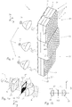
- Figure 1 shows a lighting device 1 for a motor vehicle headlight, which can correspond to the light module according to the invention.
- the lighting device 1 comprises a projection device 2, which is formed from a multiplicity of micro-optic systems 3 arranged in a matrix, each micro-optic system 3 having a micro-entry optic 30, a micro-exit optic 31 assigned to the micro-entry optic 30 and one between the micro- Entry optics 30 and the micro-exit optics 31 arranged micro-aperture 32 .
- Figure 1 It can be seen that the matrix-like arrangement of the micro-optical systems 3 extends in two directions X (horizontal) and Y (vertical) which are substantially orthogonal to the main emission direction Z. That in the Figures 1, 1a and 1b As described above, the coordinate system shown is related to the lighting device 1 in its normal installation position.
- light distributions can be generated which are a superimposition of a plurality of micro light distributions (as for example in FIG Figure 6 ) -
- Light distributions that are formed by individual micro-optical systems - are formed.
- Figure 7 shows an example of such a light distribution, which is designed as a low-beam light distribution 8 with a light-dark boundary with an asymmetry increase 80 .
- micro-optic systems are grouped into certain micro-optic system groups (see below or above), then each micro-optic system group is set up to form a partial light distribution.
- the partial light distributions are also superimpositions of several micro light distributions.
- the light distribution or the total light distribution is a superposition of partial light distributions.
- Each micro-optic system 3 preferably consists of exactly one micro-entry optic 30, exactly one micro-exit optic 31 and exactly one micro-aperture 32 ( Figure 1a ).
- all micro-entry optics 30 form, for example, one-piece entry optics 4.
- all micro-exit optics 31 form, for example, one-piece exit optics 5 and the micro-shutters 32 form, for example, one-piece aperture devices 6.
- the entry optics 4, the exit optics 5 and the aperture device 6 a projection device 2, for example in one piece.
- the projection device 2 is not designed in one piece.
- the micro entry optics 30, the micro exit optics 31 and the micro diaphragms 32 can, for example, be applied to one or more, preferably translucent, substrate (s) 40, 50, 51, 52, 60, for example made of glass or plastic.
- the diaphragm device 6 is arranged in a plane which is essentially orthogonal to the main emission direction Z of the projection device 2 - in the intermediate image plane 322 .
- all of the micro-diaphragms 32 are also located in the intermediate image plane 322.
- the entry optics 4, the exit optics 5 and the diaphragm device 6 are arranged in planes which are essentially parallel to one another.
- Figure 1a schematically shows an enlarged exploded view of one of the micro-optical systems 3 of FIG Figure 1.
- Figure 1b shows section AA of the Figure 1a ,
- the substrates 40, 50, 51, 52, 60 have been omitted in this illustration for the sake of simplicity.
- the Figure 1a shows that the micro-aperture 32 can have an optically effective edge 320 .
- the micro diaphragm 32 is spaced apart from the micro exit optics 31 by a distance d .
- the optically effective edge 320 can be set up or designed to generate the light-dark boundary of the micro-light distribution - a so-called micro-light-dark boundary 3200, 3201 (see Figure 6 ). At this point it should be on Figure 6 Be referenced.
- Figure 6 shows various shapes of the optically active edges 320a, 320b, 320c, 320d, 320e of a micro-aperture 32, as well as micro-light distributions corresponding to these shapes, which for example have a substantially horizontal micro-light-dark boundary 3201 or a micro-light-dark boundary with an asymmetry increase 3201.
- a micro light distribution is formed by light passing through the respective micro optical system 3.
- Each micro-optical system 3 therefore preferably forms exactly one micro-light distribution and vice versa: each micro-light distribution is preferably formed by exactly one micro-optical system 3.
- the optically effective edge 320, 320a, 320b, 320c, 320d, 320e can have different courses. If the micro-aperture 32, as in Figure 1b shown as an opening 321, 321a, 321b, 321c, 321d, 321e in an otherwise opaque plate, the optically active edge 320, 320a, 320b, 320c, 320d, 320e, which in this case is designed as a breakthrough limit, a closed form (see also Figure 6 ).
- At least part of the optically active edge 320, 320a, 320b, 320c, 320d, 320e is set up / formed for shaping / forming the micro-light-dark boundary 3200, 3201.
- Micro-shutters shown is the lower part of the optically active edge 320, 320a, 320b, 320c, 320d, 320e.
- the optically effective edge 320, 320a, 320b, 320c, 320d, 320e is only sharply imaged with light of a specific color or a specific wavelength.
- the optically effective edge 320, 320a, 320b, 320c, 320d, 320e of the micro diaphragm 32 which is spaced by this focal distance from the micro exit optics 31 (the distance d is equal to the focal length in this case), in the form of a micro-light-dark boundary with a Violet color fringe shown when the micro-optical system is irradiated with white light, for example a semiconductor-based light source, preferably an LED light source.
- the violet color of the color fringe is due to a mixture of blue and red components of the white light.
- the distance d is changed by shifting the micro-aperture 32 along the main emission direction Z. This also changes the color of the color fringe, because the micro-diaphragm no longer lies at an intersection of the green rays (light rays from with a light wavelength from the green spectral range) with the optical axis of the micro-exit optics, but rather at an intersection of the red or the blue (light) rays with the optical axis of the micro exit optics.
- the distance d can therefore be selected as a function of the light wavelength ⁇ d .
- micro-optical system 3 In order to counter the problem of the color fringe and to compensate for it, the entirety of the micro-optical system 3 is divided into at least two micro-optical system groups G1, G2, G3 .
- Figure 1 shows for example three micro-optical system groups G1, G2, G3.
- Each micro-optical system group G1, G2, G3 is assigned a predetermined light wavelength range (eg green range), preferably a predetermined light wavelength ⁇ G1 , ⁇ c 2 , ⁇ G3 .
- each micro-optical system group includes micro-optical systems whose micro-diaphragms can only be emitted by light with light wavelengths ⁇ G1 , ⁇ G2 , ⁇ G3 from the specified light wavelength range, preferably by light of a specified light wavelength (e.g. of approximately 555 nm) can be depicted sharply.
- the predetermined light wavelength ranges preferably the predetermined light wavelengths ⁇ G1 , ⁇ G2 , ⁇ G3 , of different micro-optical system groups G1, G2, G3 are different. It can be expedient that the different light wavelength ranges do not overlap.
- the micro-diaphragms 32 or their optically active edges 320, 320a, 320b, 320c, 320d, 320e in the light of at least one light wavelength from the specified light wavelength range preferably the specified light wavelength ⁇ G1 , ⁇ G2 , ⁇ G3 .
- the specified light wavelength ⁇ G1 , ⁇ G2 , ⁇ G3 arise in the micro photo -Light-dark transitions or - borders that have color fringes in different colors.
- the color fringes in the light image are also superimposed, whereby a color compensation effect is achieved in which the color of a color fringe is adapted to the overall light distribution or the overall light distribution.
- the predetermined light wavelength ranges, in particular the predetermined light wavelengths are preferably selected such that a white color fringe is produced.
- micro-diaphragms 32 of each micro-optical system group G1 , G2, G3 can be combined to form a micro-diaphragm group, whereby the micro-diaphragm groups can be of identical design.
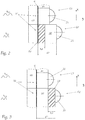
- each micro-optics system 3 at least a part of the micro-aperture 32 is spaced from the micro-exit optics 31 by a distance d, d1, d2, d3, the distance d, d1, d2, d3 from a light wavelength ⁇ d , ⁇ G1 , ⁇ G2 , ⁇ G3 from a predetermined light wavelength range or from one of the predetermined light wavelength range and is essentially the same within the same micro-optical system group G1, G2, G3.
- the distances d1, d2, d3 can be selected differently in the micro-optical systems 3 from different micro-optical system groups G1, G2, G3.
- micro-diaphragms 32 are spaced the same distance from the respective micro-exit optics, this distance d1, d2, d3 according to a light wavelength from the predetermined, this micro-optical system group G1, G2, G3 assigned light wavelength range, preferably the predetermined light wavelength ⁇ G1 , ⁇ G2 , ⁇ G3 is selected.
- the micro-optical systems 3 from two or more different micro-optical system groups G1, G2, G3 have two or more different distances d1, d2, d3 between their micro-diaphragms 32 and the respective micro-exit optics 31.
- Each micro-optical system group G1, G2, G3 is set up, micro-aperture 32 in the light of the at least one light wavelength to sharply image a predetermined light wavelength range, preferably a predetermined light wavelength.
- the micro-aperture is sharply imaged by green light with a light wavelength of approx. 555 nm.
- the differences ⁇ d 12 , ⁇ d 23 between the distances d1, d2, d3 in different micro-optical system groups G1, G2, G3 can be approximately 0.01 mm to approximately 0.12 mm, preferably from approximately 0.01 mm to approximately 0 .06 mm, in particular from about 0.01 mm to about 0.03 mm.
- the position of the micro-diaphragms in a micro-optical system group can be matched to a predetermined light wavelength range assigned to this micro-optical system group, preferably to a light wavelength.
- the micro-optics system group is to image the micro-diaphragms for green light (from the green region of the spectrum with light wavelengths from approximately 490 nm to approximately 575 nm: ⁇ ⁇ 490 - 575 nm, in particular ⁇ ⁇ 555 nm) determines the position of the intermediate image plane for these wavelengths and then positions the micro-diaphragms of the micro-optical system group in the green intermediate image plane or in the intersection of the green rays with the optical axis of the micro-exit optics.
- the micro-diaphragms are at a distance from the micro-exit optics, which is matched to the green light and is therefore related to the corresponding light wavelength.
- the position of the micro-diaphragms is determined as a function of the light wavelength from a different light wavelength range of the spectrum.
- Other areas of the spectrum are, for example: violet area (violet light) with a light wavelength of about 380 nm to about 420 nm ( ⁇ ⁇ 380 - 420 nm); blue area (blue light) with light wavelength from about 420 nm to about 490 nm ( ⁇ ⁇ 420 - 490 nm); yellow area (yellow light) with light wavelength of about 575 nm to about 585 nm ( ⁇ ⁇ 575 - 585 nm); orange area (orange light) with light wavelength from about 585 nm to about 650 nm ( ⁇ ⁇ 585 - 650 nm), and red area (red light) with light wavelength from about 650 nm to about 750 nm ( ⁇ ⁇ 650 - 750 nm)
- the optically active edges 320, 320a, 320b, 320c, 320d, 320e within the same micro-optical system group can be sharply imaged with light from a predetermined light wavelength range, preferably a predetermined light wavelength. That is, the light / dark transition (transitions) generated by the optically active edges 320, 320a, 320b, 320c, 320d, 320e, for example light / dark boundary (s), has one Color fringe of a corresponding color.
- a shift of the micro-aperture (green focal point) spaced about 0.7 mm from the micro exit optics leads in the horizontal direction to the micro exit optics or away from the micro exit optic Micro exit optics to a red or a blue color border at the micro-light-dark transition or the border.
- shifting the micro-aperture by 0.03mm to the micro-exit optics (or the micro-exit optics to the micro-aperture results in an orange colored border).
- a superimposition of the color fringes in different colors in the photograph leads to a clear compensation of the color fringe.
- a yellow-reddish color fringe can be overlaid with a violet color fringe and thereby produce an essentially white color fringe - compensation.
- a projection device which comprises two micro-optical system groups, which consist of an equal number of micro-optical systems, the micro exit optics of a micro-optical system group being approximately 0.06 mm thicker than that of others.
- the sharpness factor can then be adjusted to the light distribution.
- the different distances d1, d2, d3 in the different micro-optical system groups G1, G2, G3 can be achieved, for example, by different thicknesses of the micro-exit optics 32 themselves, the corresponding substrates or the corresponding adhesive layers between the corresponding substrate and the micro-exit optics.
- Figure 1 reveals that the micro exit optics 32 are applied to a substrate 50, 51, 52.
- the substrate 50, 51, 52 has a different thickness depending on the micro-optical system group G1, G2, G3.
- the thickness of the substrate 50, 51, 52 in the corresponding micro-optical system group G1, G2, G3 defines the distances d1, d2, d3 between the micro-diaphragms 32 and the micro exit optics 31 of this micro-optical system group G1, G2, G3. It is also conceivable to design the substrate 60 of the diaphragm device 6 or the substrate 40 of the entrance optics 4 for the different micro-optical system groups G1, G2, G3 to have different thicknesses.
- micro-diaphragms of a thickness D, so that, for example, a rear, with respect to the micro-exit optics 31 (in the main emission direction Z) distal part 32a of its optically active edges is sharply imaged with light of a first light wavelength ⁇ G11 from the predetermined light wavelength range and a front part 32b of its optically active edges, which is proximal to the micro-exit optics 31, is sharply imaged with light of a second light wavelength ⁇ G12 from the predetermined light wavelength range.
- the distal part 32a at an intersection S ⁇ G 11 the rays of the light wavelength ⁇ G11 with the optical axis OA of the micro-optical system 3 and the proximal part 32b at an intersection S ⁇ G 12 the rays of light wavelength ⁇ G12 are arranged with the optical axis OA of the micro-optical system 3.
- the micro-aperture 32 can be approximately 0 , 12 mm thick, whereby its center can be spaced from the micro exit optics 31 by approximately 0.7 mm.
- the distal part 32a of the optically active edge of the micro-aperture 32 becomes an intersection point S ⁇ G 11 the red rays with the optical axis OA of the micro exit optics 31 and the proximal part 32b of the optically active edge of the micro diaphragm 32 at an intersection S ⁇ G 12 , the blue rays with the optical axis OA of the micro exit optics.
- Different parts of the optically Effective edges, such as the distal or proximal part are superimposed in the form of micro-light-dark transitions or borders with color fringes in different colors in the photo. This overlay can also compensate for the color fringe of the cut-off line.
- micro-exit optics of different thicknesses whether achieved by a thicker substrate, thicker adhesive layer or thicker micro-exit optic body - are preferred.
- Micro-diaphragms of different thicknesses can only be produced using an application method (lithographic) and lead to an air gap in the projection device.
- Micro-panels of different thicknesses cannot be connected to flat glass plates, such as those used in the imprint process.
- Micro-exit optics of different thicknesses can, however, be easily manufactured using a tool.
- the micro exit optics 31 of each micro optic system 3 have a light exit surface with a predetermined curvature k1, k2 , the predetermined curvature k1, k2 (the value of the predetermined curvature) of a light wavelength from a predetermined light wavelength range or from one of the predetermined light wavelength ranges, preferably depending on one of the light wavelengths ⁇ G1 , ⁇ G2 , ⁇ G3 and is essentially the same within the same micro-optical system group G1 , G2, G3, the predetermined curvatures k1, k2 for the micro- Optical systems 3 from different micro-optical system groups G1 , G2, G3 are different.
- FIG. 5 shows schematically two micro exit optics 31 from different micro optic system groups G1 , G2 and these micro exit optics 31 upstream micro diaphragms 32. It should be noted that the micro diaphragms in this example are at the same distance from the micro exit optics 31 are arranged. It is understood that this is not a limitation.
- the distance between the micro-aperture and the micro-exit optics can also vary here, as described above and be adapted to the light wavelength.
- the light exit surfaces of the micro exit optics 31 of the Figure 5 are curved differently. This means that the micro-diaphragms 32 of the micro-optical system 3 of a first micro-optical system group G1 at an intersection S ⁇ G 1 the rays of the light wavelength ⁇ G1 with the optical axis OA of the corresponding micro-optical system 3 and the micro-diaphragms 32 of the micro-optical systems 3 of a second micro-optical system group G2 at an intersection S ⁇ G 2 the rays of light wavelength ⁇ G2 can be located with the optical axis OA of the corresponding micro-optical system 3.
- the optically effective edges of the micro-diaphragms 32 are imaged as micro-light-dark transitions or boundaries 3200, 3201 with color fringes in different colors.
- the light wavelengths can be selected in such a way that the color fringing that occurs after the overlay is white.
- these exemplary embodiments can be combined with one another.
- the total thickness of the projection device can also influence the elongated extent of the entire light module in which the projection device is used, and thus, for example, the overall depth can be adjusted.
- the micro-optical systems 3 of Figure 5 an adhesive layer like in the Figures 2 or 3 or a thicker substrate like in Figure 1 provided.
- Figure 6 Examples of micro-diaphragms 32 with differently shaped openings 321a, 321b, 321c, 321d, 321e and of micro-light distributions that can be generated by the respective shape of the opening.
- Figure 6 reveals two different forms of micro-light-dark boundaries: an essentially horizontal micro-light-dark boundary 3201 and a micro-light-dark boundary with an asymmetry increase 3201.
- a superposition of the micro-light distributions of the same micro-optical system group are formed in the light image a partial light distribution which has a partial light-dark boundary with a color fringe of a predetermined color, the predetermined color depending on the predetermined light wavelength range, preferably on the predetermined light wavelength ,
- the partial light distributions that overlap in the photograph form a light distribution or total light distribution, such as the low beam 8 in the Figure 7
- the micro-light distributions with the micro-light-dark boundaries having the asymmetry increase 3201 lead to partial light-dark limits with an asymmetry increase, each partial light-dark boundary having the color fringe in the predetermined color.
- This forms the light-dark boundary with the asymmetry increase 80 the color fringe of which has a color which is determined by the colors of the color fringes of the partial light distribution.
- the color of the color fringe of the light-dark boundary with the asymmetry increase 80 in the low-beam light distribution 8 is preferably white.
- the different micro-optical system groups can be designed separately from one another. It is conceivable that the different micro-optical system groups are spaced apart.
- the entrance optics, the exit optics and the diaphragm device can be arranged on separate, preferably transparent substrates.
- the light source 7 emits light which is projected by means of the projection device 2 into an area in front of the lighting device in the form of a light distribution, for example a low-beam light distribution 8 with a light-dark boundary, for example a light-dark boundary with an asymmetry increase 80.
- the light distribution is formed from a multiplicity of overlapping partial light distributions, each with a partial light-dark boundary.
- Each partial light distribution is formed by exactly one micro-optical system group.
- the light source 7 can expediently be set up to generate collimated light.
- the light source 7 can be a light-collimating optical element, such as a collimator 9 in Figure 1 and a preferably semiconductor-based lighting element, for example an LED light source 10, located in front of the collimator 9.
- the light-collimating optical element can also be designed as a light-collimating front lens or a TIR lens (not shown).
- the light source 7 has three light-emitting regions 70, 71, 72.
- Each individual light-emitting area can be one or more semiconductor-based light sources, preferably LED light sources, and can be controlled, for example switched on and off, independently of the other light-emitting areas of the light source 7.
Abstract
Projektionseinrichtung (2) für ein Lichtmodul (1) eines Kraftfahrzeugscheinwerfers, die aus einer Vielzahl matrixartig angeordneter Mikro-Optiksysteme (3) gebildet ist, wobei jedes Mikro-Optiksystem (3) eine Mikro-Eintrittsoptik (30), eine der Mikro-Eintrittsoptik (30) zugeordnete Mikro-Austrittsoptik (31) und eine Mikro-Blende (32) aufweist, wobei alle Mikro-Eintrittsoptiken (31) eine Eintrittsoptik (4), alle Mikro-Austrittsoptiken (31) eine Austrittsoptik (5) und die Mikro-Blenden (32) eine Blendenvorrichtung (6) bilden, wobei die Blendenvorrichtung (6) in einer im Wesentlichen zur Hauptabstrahlrichtung (Z) der Projektionseinrichtung (2) orthogonal stehenden Ebene angeordnet ist und die Eintrittsoptik (4), die Austrittsoptik (5) und die Blendenvorrichtung (6) in im Wesentlichen zueinander parallelen Ebenen angeordnet sind, wobei die Gesamtheit der Mikro-Optiksysteme (3) in zumindest zwei Mikro-Optiksystem-Gruppen (G1, G2, G3) unterteilt ist, wobei die Mikro-Blenden (32) der Mikro-Optiksysteme (3) einer jeden Mikro-Optiksystem-Gruppe (G1, G2, G3) durch Licht zumindest einer Lichtwellenlänge (λ<sub>G1</sub>, λ<sub>G2</sub>, λ<sub>G3</sub>) aus einem vorgegebenen Lichtwellenlängenbereich scharf abbildbar sind und die vorgegebenen Lichtwellenlängenbereiche bei unterschiedlichen Mikro-Optiksystem-Gruppen (G1, G2, G3) unterschiedlich sind.Projection device (2) for a light module (1) of a motor vehicle headlight, which is formed from a plurality of micro-optic systems (3) arranged in a matrix, each micro-optic system (3) having a micro-entry optic (30), one of the micro-entry optics ( 30) assigned micro exit optics (31) and a micro diaphragm (32), all micro entry optics (31) one entry optics (4), all micro exit optics (31) one exit optics (5) and the micro diaphragms (32) form a diaphragm device (6), the diaphragm device (6) being arranged in a plane which is essentially orthogonal to the main emission direction (Z) of the projection device (2) and the entrance optics (4), the exit optics (5) and the diaphragm device (6) are arranged in substantially mutually parallel planes, the entirety of the micro-optical systems (3) being subdivided into at least two micro-optical system groups (G1, G2, G3), the micro-diaphragms (32) of the micro -op tic systems (3) of each micro-optical system group (G1, G2, G3) by light of at least one light wavelength (λ <sub> G1 </sub>, λ <sub> G2 </sub>, λ <sub> G3 < / sub>) can be depicted sharply from a given light wavelength range and the given light wavelength ranges are different for different micro-optical system groups (G1, G2, G3).
Description
Die Erfindung betrifft eine Projektionseinrichtung für ein Lichtmodul eines Kraftfahrzeugscheinwerfers, die aus einer Vielzahl matrixartig angeordneter Mikro-Optiksysteme gebildet ist, wobei jedes Mikro-Optiksystem eine Mikro-Eintrittsoptik, eine der Mikro-Eintrittsoptik zugeordnete Mikro-Austrittsoptik und eine zwischen der Mikro-Eintrittsoptik und der Mikro-Austrittsoptik angeordnete Mikro-Blende aufweist, wobei alle Mikro-Eintrittsoptiken eine Eintrittsoptik, alle Mikro-Austrittsoptiken eine Austrittsoptik und die Mikro-Blenden eine Blendenvorrichtung bilden, wobei die Blendenvorrichtung in einer im Wesentlichen zur Hauptabstrahlrichtung der Projektionseinrichtung orthogonal stehenden Ebene angeordnet ist und die Eintrittsoptik, die Austrittsoptik und die Blendenvorrichtung in im Wesentlichen zueinander parallelen Ebenen angeordnet sind.The invention relates to a projection device for a light module of a motor vehicle headlight, which is formed from a plurality of micro-optic systems arranged in a matrix, each micro-optic system having a micro-entry optic, a micro-exit optic assigned to the micro-entry optic and one between the micro-entry optic and the micro-exit optics arranged micro-aperture, wherein all micro-entry optics an entry optics, all micro-exit optics form an exit optics and the micro-apertures form a diaphragm device, the diaphragm device being arranged in a plane substantially orthogonal to the main emission direction of the projection device and the entrance optics, the exit optics and the diaphragm device are arranged in planes which are essentially parallel to one another.
Darüber hinaus betrifft die Erfindung ein Lichtmodul mit zumindest einer solchen Projektionseinrichtung.Furthermore, the invention relates to a light module with at least one such projection device.
Projektionseinrichtungen der oben genannten Art und Lichtmodule mit solchen Projektionseinrichtungen sind aus dem Stand der Technik bekannt.Projection devices of the type mentioned above and light modules with such projection devices are known from the prior art.
Die internationale Anmeldung
Es ist daher die Aufgabe der vorliegenden Erfindung, die Nachteile des Stands der Technik zu beseitigen und eine Projektionseinrichtung sowie ein Lichtmodul bereitzustellen, die den Farbsaum kompensieren.It is therefore the object of the present invention to eliminate the disadvantages of the prior art and to provide a projection device and a light module which compensate for the color fringing.
Die Aufgabe wird mit einer Projektionseinrichtung der oben genannten Art erfindungsgemäß dadurch gelöst, dass die Gesamtheit der Mikro-Optiksysteme in zumindest zwei Mikro-Optiksystem-Gruppen unterteilt ist, wobei die Mikro-Blenden der Mikro-Optiksysteme einer jeden Mikro-Optiksystem-Gruppe durch Licht zumindest einer Lichtwellenlänge aus einem vorgegebenen Lichtwellenlängenbereich, vorzugsweise durch Licht einer vorgegebenen Lichtwellenlänge, scharf abbildbar sind und die vorgegebenen Lichtwellenlängenbereiche bei unterschiedlichen Mikro-Optiksystem-Gruppen unterschiedlich sind und vorzugsweise nicht überlappen.The object is achieved according to the invention with a projection device of the type mentioned above in that the entirety of the micro-optical systems is divided into at least two micro-optical system groups, the micro-diaphragms of the micro-optical systems of each micro-optical system group being illuminated at least one light wavelength from a predefined light wavelength range, preferably by light of a predefined light wavelength, can be depicted sharply and the predefined light wavelength ranges are different in different micro-optical system groups and preferably do not overlap.
Hierdurch wird einer jeden Mikro-Optiksystem-Gruppe eine, vorzugsweise genau eine Lichtwellenlänge zugeordnet. Jede Mikro-Optiksystem-Gruppe ist somit durch eine Lichtwellenlänge aus einem vorgegebenen Lichtwellenlängenbereich, vorzugsweise durch eine vorgegebene Lichtwellenlänge charakterisiert. Es lässt sich darüber hinaus sagen, dass eine der Mikro-Optiksystem-Gruppen nur Licht zumindest einer Lichtwellenlänge aus einem vorgegebenen Lichtwellenlängenbereich, vorzugsweise einer vorgegebenen Lichtwellenlänge fokussiert. Andere Mikro-Optiksystem-Gruppen sind hinsichtlich des Lichts einer Lichtwellenlänge aus diesem vorgegebenen Lichtwellenlängenbereich, vorzugsweise der vorgegebenen Lichtwellenlänge defokussiert.As a result, each micro-optical system group is assigned one, preferably exactly one, light wavelength. Each micro-optical system group is thus characterized by a light wavelength from a predetermined light wavelength range, preferably by a predetermined light wavelength. It can also be said that one of the micro-optical system groups focuses only light of at least one light wavelength from a predetermined light wavelength range, preferably a predetermined light wavelength. Other micro-optical system groups are defocused with respect to the light of a light wavelength from this predetermined light wavelength range, preferably the predetermined light wavelength.
Die mithilfe der Projektionseinrichtung erzeugten Lichtverteilungen werden als eine Überlagerung einer Vielzahl von Mikro-Lichtverteilungen - Lichtverteilungen, die durch einzelne Mikro-Optiksysteme geformt werden - gebildet. Weiters ist jede Mikro-Optiksystem-Gruppe zum Formen einer Teil-Lichtverteilung eingerichtet. Die Teil-Lichtverteilungen sind Überlagerungen von jenen Mikro-Lichtverteilungen, die mithilfe der zu der entsprechenden Mikro-Optiksystem-Gruppe gehörenden Mikro-Optiksysteme gebildet/ geformt werden. Die Lichtverteilung beziehungsweise die Gesamtlichtverteilung ist auch eine Überlagerung von den Teil-Lichtverteilungen einzelner Mikro-Optiksystem-Gruppen.The light distributions generated with the aid of the projection device are formed as an overlay of a multiplicity of micro-light distributions - light distributions which are formed by individual micro-optic systems. Furthermore, each micro-optical system group is set up to form a partial light distribution. The partial light distributions are superimpositions of those micro light distributions that are made using the micro-optical systems belonging to the corresponding micro-optical system group are formed / shaped. The light distribution or the total light distribution is also a superposition of the partial light distributions of individual micro-optical system groups.
Durch das oben genannte scharfe Abbilden der Mikro-Blenden beispielsweise ihrer optisch wirksamen Kanten im Licht zumindest einer Lichtwellenlänge aus dem vorgegebenen Lichtwellenlängenbereich, vorzugsweise der vorgegebenen Lichtwellenlänge entstehen im Lichtbild Mikro-Hell-Dunkel-Übergänge beziehungsweise -Grenzen, die Farbsäume in unterschiedlichen Farben aufweisen. Durch Überlagerung der Mikro-Hell-Dunkel-Übergänge beziehungsweise -Grenzen werden die Farbsäume im Lichtbild ebenfalls überlagert, wodurch ein Farbkompensationseffekt erreicht wird, bei dem die Farbe eines Farbsaums der gesamten Lichtverteilung beziehungsweise der Gesamtlichtverteilung angepasst wird. Vorzugsweise sind die vorgegebenen Lichtwellenlängenbereiche, insbesondere die vorgegebenen Lichtwellenlängen derart gewählt, dass ein weißer Farbsaum entsteht.The above-mentioned sharp imaging of the micro-diaphragms, for example their optically active edges in the light of at least one light wavelength from the predetermined light wavelength range, preferably the predetermined light wavelength, results in micro-light-dark transitions or boundaries in the light image which have color fringes in different colors. By superimposing the micro-light-dark transitions or boundaries, the color fringes in the light image are also superimposed, whereby a color compensation effect is achieved in which the color of a color fringe is adapted to the overall light distribution or the overall light distribution. The predetermined light wavelength ranges, in particular the predetermined light wavelengths, are preferably selected such that a white color fringe is produced.
Somit wird eine Farbkompensation ohne Achromat, spezielle Positionierung der Mikro-Austrittsoptiken einen zusätzlichen Prozessschritt oder zusätzliche Bauteile ermöglicht.This enables color compensation without achromatic, special positioning of the micro exit optics, an additional process step or additional components.
Es kann darüber hinaus mit Vorteil vorgesehen sein, dass in jedem Mikro-Optiksystem die Mikro-Blende von der Mikro-Austrittsoptik um einen Abstand beabstandet ist, wobei der Abstand von der zumindest einen Lichtwellenlänge aus einem vorgegebenen Lichtwellenlängenbereich, vorzugsweise von einer vorgegebenen Lichtwellenlänge abhängt und innerhalb derselben Mikro-Optiksystem-Gruppe im Wesentlichen gleich ist, wobei die Abstände bei den Mikro-Optiksystemen aus unterschiedlichen Mikro-Optiksystem-Gruppen unterschiedlich sind.In addition, it can advantageously be provided that in each micro-optical system the micro-diaphragm is spaced a distance from the micro-exit optic, the distance being dependent on the at least one light wavelength from a predetermined light wavelength range, preferably on a predetermined light wavelength is essentially the same within the same micro-optical system group, the distances between the micro-optical systems from different micro-optical system groups being different.
Dies bedeutet, dass innerhalb einer und derselben Mikro-Optiksystem-Gruppe die Mikro-Blenden von den jeweiligen Mikro-Austrittsoptiken um gleichen Abstand beabstandet sein können, wobei dieser Abstand gemäß zumindest einer Lichtwellenlänge aus dem vorgegebenen, dieser Mikro-Optiksystem-Gruppe zugeordneten Lichtwellenlängenbereich, vorzugsweise zumindest einer vorgegebenen Lichtwellenlänge gewählt ist. Dabei können die Mikro-Optiksysteme aus zwei beziehungsweise mehr unterschiedlichen Mikro-Optiksystem-Gruppen zwei beziehungsweise mehr unterschiedliche Abstände zwischen ihren Mikro-Blenden und den jeweiligen Mikro-Austrittsoptiken aufweisen. Jede Mikro-Optiksystem-Gruppe kann eingerichtet sein, Mikro-Blende im Licht zumindest einer Lichtwellenlänge aus einem vorgegebenen Lichtwellenlängenbereich, vorzugsweise einer vorgegebenen Lichtwellenlänge scharf abzubilden.This means that within one and the same micro-optical system group, the micro-diaphragms can be spaced the same distance from the respective micro-exit optics, this distance according to at least one light wavelength from the predetermined light wavelength range assigned to this micro-optical system group, preferably at least one predetermined light wavelength is selected. The micro-optical systems can consist of two or more different micro-optical system groups have two or more different distances between their micro-diaphragms and the respective micro-exit optics. Each micro-optical system group can be set up to sharply image micro-diaphragms in the light of at least one light wavelength from a predetermined light wavelength range, preferably a predetermined light wavelength.
Weiters kann es zweckmäßig sein, wenn Unterschiede zwischen den Abständen in unterschiedlichen Mikro-Optiksystem-Gruppen etwa 0,01 mm bis etwa 0,12 mm, vorzugsweise von etwa 0,01 mm bis etwa 0,06 mm, insbesondere von etwa 0,01 mm bis etwa 0,03 mm betragen, wobei die Mikro-Austrittsoptiken eine Schnittweite - den Abstand zwischen dem Brennpunkt und der Lichteintrittsfläche - aufweisen, die von der zumindest einen Lichtwellenlänge aus einem vorgegebenen Lichtwellenlängenbereich und von ihrem Durchmesser abhängt.Furthermore, it can be expedient if differences between the distances in different micro-optical system groups are from about 0.01 mm to about 0.12 mm, preferably from about 0.01 mm to about 0.06 mm, in particular from about 0.01 mm to about 0.03 mm, the micro exit optics having an intersection - the distance between the focal point and the light entry surface - which depends on the at least one light wavelength from a predetermined light wavelength range and on its diameter.
Beispielsweise können Mikro-Austrittsoptiken für grünes Licht ausgelegt werden. Wenn die Mikro-Austrittsoptiken zum Beispiel als plankonvexe Linsen mit einem Linsendurchmesser von etwa 2 mm ausgebildet sind, können sie für Licht mit einer Lichtwellenlänge von etwa 555 nm ("grünes Licht"), eine Schnittweite von etwa 0,7 mm ("grüner Brennpunkt") aufweisen (siehe Beispiel in der Figurenbeschreibung).For example, micro exit optics can be designed for green light. If, for example, the micro-exit optics are designed as plano-convex lenses with a lens diameter of approximately 2 mm, they can have an intersection of approximately 0.7 mm ("green focal point") for light with a light wavelength of approximately 555 nm ("green light") ") have (see example in the figure description).
Es sei an dieser Stelle angemerkt, dass die Position der Mikro-Blenden in einer Mikro-Optiksystem-Gruppe auf einen dieser Mikro-Optiksystem-Gruppe zugeordneten vorgegebenen Lichtwellenlängenbereich, vorzugsweise auf eine Lichtwellenlänge abgestimmt werden kann. Beispielsweise, wenn die Mikro-Optiksystem-Gruppe die Mikro-Blenden für grünes Licht (aus grünem Bereich des Spektrums mit Lichtwellenlängen von etwa 490 nm bis etwa 575 nm: λ ∼ 490 - 575 nm, insbesondere λ ∼ 555 nm) abbilden soll, wird die Position der Zwischenbildebene für diese Wellenlängen bestimmt und anschließend die Mikro-Blenden der Mikro-Optiksystem-Gruppe in die grüne Zwischenbildebene beziehungsweise in den Schnittpunkt der grünen Strahlen mit der optischen Achse der Mikro-Austrittsoptik positioniert. Dabei weisen die Mikro-Blenden einen Abstand von der Mikro-Austrittsoptiken aus, der auf das grüne Licht abgestimmt ist und somit mit der entsprechenden Lichtwellenlänge zusammenhängt.It should be noted at this point that the position of the micro-diaphragms in a micro-optical system group can be matched to a predetermined light wavelength range assigned to this micro-optical system group, preferably to a light wavelength. For example, if the micro-optics system group is to image the micro-diaphragms for green light (from the green region of the spectrum with light wavelengths from approximately 490 nm to approximately 575 nm: λ ∼ 490 - 575 nm, in particular λ ∼ 555 nm) determines the position of the intermediate image plane for these wavelengths and then positions the micro-diaphragms of the micro-optical system group in the green intermediate image plane or in the intersection of the green rays with the optical axis of the micro-exit optics. The micro-diaphragms are at a distance from the micro-exit optics, which is matched to the green light and is therefore related to the corresponding light wavelength.
Die optisch wirksamen Kanten innerhalb derselben Mikro-Optiksystem-Gruppe können mit Licht aus einem vorgegebenen Lichtwellenlängenbereich, vorzugsweise einer vorgegebenen Lichtwellenlänge scharf abgebildet werden. Das heißt, der(die) durch die optische wirksamen Kanten erzeugte(n) Hell-Dunkel-Übergang(Übergänge), beispielsweise Hell-Dunkel-Grenze(n) weist(weisen) einen Farbsaum einer entsprechenden Farbe auf.The optically active edges within the same micro-optical system group can be sharply imaged with light from a predetermined light wavelength range, preferably a predetermined light wavelength. This means that the light-dark transition (transitions) generated by the optically effective edges, for example light-dark boundary (s), has a color fringe of a corresponding color.
Es kann mit Vorteil vorgesehen sein, dass die Mikro-Austrittsoptik eines jeden Mikro-Optiksystems eine Lichtaustrittsfläche mit einer vorgegebenen Krümmung aufweist, wobei die vorgegebene Krümmung (der Wert der vorgegebenen Krümmung) von der zumindest einen Lichtwellenlänge aus einem vorgegebenen Lichtwellenlängenbereich, vorzugsweise von einer der vorgegebenen Lichtwellenlängen abhängt und innerhalb derselben Mikro-Optiksystem-Gruppe im Wesentlichen gleich ist, wobei die vorgegebenen Krümmungen bei den Mikro-Optiksystemen aus unterschiedlichen Mikro-Optiksystem-Gruppen unterschiedlich sind.It can advantageously be provided that the micro-exit optics of each micro-optic system have a light exit surface with a predetermined curvature, the predetermined curvature (the value of the predetermined curvature) of the at least one light wavelength from a predetermined light wavelength range, preferably one of the depends on predetermined light wavelengths and is essentially the same within the same micro-optical system group, the predetermined curvatures being different in the micro-optical systems from different micro-optical system groups.
Außerdem kann vorgesehen sein, dass zumindest ein Teil der Mikro-Blenden jeder Mikro-Optiksystem-Gruppe optisch wirksame Kanten aufweist, die zum Abbilden einer im Wesentlichen horizontalen (mit oder ohne Asymmetrieanstieg) Mikro-Hell-Dunkel-Grenze ausgebildet sind.In addition, it can be provided that at least some of the micro-diaphragms of each micro-optical system group have optically effective edges, which are designed to represent an essentially horizontal (with or without increase in asymmetry) micro-light-dark boundary.
Dabei kann es weitere Vorteile geben, wenn die Mikro-Hell-Dunkel-Grenzen bei unterschiedlichen Mikro-Optiksystem-Gruppen durch Licht der unterschiedlichen Lichtwellenlängen scharf abbildbar sind.There can be further advantages here if the micro-light-dark limits in different micro-optical system groups can be depicted sharply by light of the different light wavelengths.
Hinsichtlich des Unterbringens der Mikro-Optiksystem-Gruppe in einem Kraftfahrzeugscheinwerfer kann es nützlich sein, wenn die unterschiedlichen Mikro-Optiksystem-Gruppen getrennt voneinander ausgebildet sind und vorzugsweise voneinander beabstandet sind.With regard to accommodating the micro-optical system group in a motor vehicle headlight, it can be useful if the different micro-optical system groups are formed separately from one another and are preferably spaced apart from one another.
Weiters kann es mit Vorteil vorgesehen sein, dass die Mikro-Blenden einer jeden Mikro-Optiksystem-Gruppe zu einer Mikro-Blenden-Gruppe zusammengefasst sind und die Mikro-Blenden-Gruppen identisch ausgebildet sind, wobei vorzugsweise jede Mikro-Blende als ein Plättchen aus einem lichtundurchlässigen Material mit einem Durchbruch ausgebildet ist, wobei insbesondere jede Mikro-Blende entlang der Hauptabstrahlrichtung eine endliche Dicke, beispielsweise von etwa 0,01 mm bis etwa 0,12 mm, vorzugsweise von etwa 0,06 mm, aufweist.Furthermore, it can advantageously be provided that the micro-diaphragms of each micro-optical system group are combined to form a micro-diaphragm group and the micro-diaphragm groups are of identical design, each micro-diaphragm preferably being a plate an opaque material with an opening is formed, in particular each micro-aperture along the main radiation direction a finite Thickness, for example from about 0.01 mm to about 0.12 mm, preferably from about 0.06 mm.
Darüber hinaus wird die oben genannte Aufgabe mit einem Lichtmodul mit zumindest einer erfindungsgemäßen Projektionseinrichtung gelöst, wobei das Lichtmodul außerdem eine Lichtquelle aufweist, wobei die Projektionseinrichtung der Lichtquelle in Lichtabstrahlrichtung nachgelagert ist und im Wesentlichen gesamtes, von der Lichtquelle erzeugtes Licht in einen Bereich vor dem Lichtmodul in Form einer Lichtverteilung mit einer Hell-Dunkel-Grenze projiziert, wobei die Lichtverteilung aus einer Vielzahl einander überlappender Teil-Lichtverteilungen mit jeweils einer Teil-Hell-Dunkel-Grenze gebildet ist und jede Teil-Lichtverteilung durch genau eine Mikro-Optiksystem-Gruppe gebildet ist.In addition, the above-mentioned object is achieved with a light module with at least one projection device according to the invention, the light module also having a light source, the projection device being arranged downstream of the light source in the light emission direction and essentially all of the light generated by the light source in an area in front of the light module projected in the form of a light distribution with a light-dark boundary, the light distribution being formed from a multiplicity of overlapping partial light distributions each with a partial light-dark boundary and each partial light distribution being formed by exactly one micro-optical system group is.
Weiters kann es vorgesehen sein, dass jede Teil-Hell-Dunkel-Grenze einen Farbsaum einer vorgegebenen Farbe aufweist und unterschiedliche Teil-Hell-Dunkel-Grenzen Farbsäume unterschiedlicher Farben aufweisen.Furthermore, it can be provided that each partial light-dark boundary has a color fringe of a predetermined color and different partial light-dark borders have color fringes of different colors.
Es kann zweckdienlich sein, wenn die Teil-Hell-Dunkel-Grenzen und die Hell-Dunkel-Grenze im Wesentlichen gerade, beispielsweise horizontal oder vertikal, verlaufen oder einen Asymmetrieanstieg aufweisen, wobei jede Farbe einer Lichtwellenlänge aus einem vorgegebenen Lichtwellenlängenbereich, vorzugsweise einer vorgegebenen Lichtwellenlänge entspricht.It may be expedient if the partial light-dark boundaries and the light-dark boundary run essentially straight, for example horizontally or vertically, or have an asymmetry increase, each color of a light wavelength from a predetermined light wavelength range, preferably a predetermined light wavelength equivalent.
Bei einer praxisbewahrten Ausführungsform kann vorgesehen sein, dass die Lichtquelle eingerichtet ist, kollimiertes Licht zu erzeugen.In a practice-proven embodiment it can be provided that the light source is set up to generate collimated light.
Darüber hinaus kann mit Vorteil vorgesehen sein, dass die Lichtquelle ein lichtkollimierendes Optikelement und ein dem lichtkollimierenden Optikelement vorgelagertes, vorzugsweise halbleiterbasiertes Leuchtelement, beispielsweise eine LED-Lichtquelle, umfasst, wobei das lichtkollimierende Optikelement beispielsweise ein Kollimator oder eine lichtkollimierende Vorsatzoptik oder eine TIR-Linse ist.In addition, it can advantageously be provided that the light source comprises a light-collimating optical element and a preferably semiconductor-based lighting element, for example an LED light source, located in front of the light-collimating optical element, the light-collimating optical element being, for example, a collimator or a light-collimating front lens or a TIR lens ,
Außerdem kann vorgesehen sein, dass die Lichtquelle zumindest zwei lichtemittierende Bereiche aufweist, wobei jeder einzelne lichtemittierende Bereich unabhängig von den anderen lichtemittierenden Bereichen der Lichtquelle steuerbar, beispielsweise ein- und ausschaltbar ist, und jedem lichtemittierenden Bereich mindestens eine, vorzugsweise genau eine Mikro-Optiksystem-Gruppe derart zugeordnet ist, dass von dem jeweiligen lichtemittierenden Bereich erzeugtes Licht direkt und nur auf die diesem lichtemittierenden Bereich zugeordnete Mikro-Optiksystem-Gruppe trifft. Dadurch wird ein dynamisches Einstellen, d.h. Einstellen im Betrieb des Lichtmoduls, der Farbe des Farbsaums der Hell-Dunkel-Grenze möglich.In addition, it can be provided that the light source has at least two light-emitting areas, each individual light-emitting area being controllable, for example, on and off, independently of the other light-emitting areas of the light source, and each light-emitting area having at least one, preferably exactly one, micro-optical system system. Group is assigned such that of the respective light-emitting area generated light directly and only hits the micro-optical system group assigned to this light-emitting area. This enables dynamic adjustment, ie adjustment in operation of the light module, of the color of the color fringe of the light-dark boundary.
Die Erfindung samt weiteren Vorteilen ist im Folgenden an Hand beispielhafter Ausführungsformen näher erläutert, die in der Zeichnung veranschaulicht sind. In dieser zeigt
-
Fig. 1 eine Beleuchtungsvorrichtung mit einer Projektionseinrichtung aus mehreren Mikro-Optiksystemen in perspektivischer Ansicht; -
Fig. 1a Explosionsdarstellung eines der Mikro-Optiksysteme derFigur 1 ; -
Fig. 1b ein Schnitt A-A des Mikro-Optiksystems derFigur 1a ; -
Fig. 2 und 3 Mikro-Optiksystem-Gruppen mit unterschiedlich beabstandeten Mikro-Blenden und Mikro-Austrittsoptiken; -
Fig. 4 ein Mikro-Optiksystem mit einer endlich dicken Mikro-Blende; -
Fig. 5 Mikro-Optiksystem-Gruppen mit unterschiedlich gekrümmten Lichtaustrittsflächen der Mikro-Austrittsoptiken; -
Fig. 6 verschiedene Formen von Mikro-Blenden und Mikro-Lichtverteilungen, und -
Fig. 7 eine Abblendlichtverteilung mit einer asymmetrischen Hell-Dunkel-Grenze.
-
Fig. 1 an illumination device with a projection device from several micro-optical systems in a perspective view; -
Fig. 1a Exploded view of one of the micro-optical systems of theFigure 1 ; -
Fig. 1b a section AA of the micro-optical systemFigure 1a ; -
2 and 3 Micro-optical system groups with differently spaced micro diaphragms and micro exit optics; -
Fig. 4 a micro-optics system with a finally thick micro-aperture; -
Fig. 5 Micro-optical system groups with differently curved light exit surfaces of the micro exit optics; -
Fig. 6 various forms of micro-shutters and micro-light distributions, and -
Fig. 7 a low beam distribution with an asymmetrical cut-off line.
Die Figuren sind schematische Darstellungen, die lediglich jene Bestandteile zeigen, die für eine Erklärung der Erfindung hilfreich sein können. Der Fachmann erkennt sofort, dass eine Projektionseinrichtung und ein Lichtmodul für einen Kraftfahrzeugscheinwerfer eine Vielzahl weiterer, hier nicht gezeigter Bestandteile aufweisen kann, wie Ein- und Verstelleinrichtungen, elektrische Versorgungsmittel und vieles mehr.The figures are schematic representations which only show those components which can be helpful for an explanation of the invention. The person skilled in the art immediately recognizes that a projection device and a light module for a motor vehicle headlight can have a large number of further components, not shown here, such as setting and adjustment devices, electrical supply means and much more.
Zur Vereinfachung der Lesbarkeit und da, wo es zweckdienlich ist, sind die Figuren mit Bezugsachsen versehen. Diese Bezugsachsen beziehen sich auf eine fachgerechte Einbaulage des Erfindungsgegenstands in einem Kraftfahrzeug und stellen ein kraftfahrzeugbezogenes Koordinatensystem dar.The figures are provided with reference axes to simplify legibility and where appropriate. These reference axes relate to a professional installation position of the subject matter of the invention in a motor vehicle and represent a motor vehicle-related coordinate system.
Darüber hinaus soll es klar sein, dass richtungsbezogene Begriffe, wie "horizontal", "vertikal", "oben", "unten" etc. im Zusammenhang mit der vorliegenden Erfindung in einer relativen Bedeutung zu verstehen sind und sich entweder auf die oben erwähnte fachgerechte Einbaulage des Erfindungsgegenstands in einem Kraftfahrzeug oder auf eine fachübliche Ausrichtung einer abgestrahlten Lichtverteilung im Lichtbild beziehungsweise im Verkehrsraum beziehen.In addition, it should be clear that direction-related terms such as "horizontal", "vertical", "top", "bottom" etc. are to be understood in the context of the present invention in a relative meaning and either refer to the above-mentioned technical Install position of the subject matter of the invention in a motor vehicle or to a customary alignment of a radiated light distribution in the photograph or in the traffic area.
Somit sind weder die Bezugsachsen noch die richtungsbezogenen Begriffe nicht einschränkend auszulegen.Thus, neither the reference axes nor the direction-related terms are to be interpreted restrictively.
Mit der Beleuchtungsvorrichtung 1 können Lichtverteilungen erzeugt werden, die als eine Überlagerung einer Vielzahl von Mikro-Lichtverteilungen (wie beispielsweise in
Vorzugsweise besteht jedes Mikro-Optiksystem 3 aus genau einer Mikro-Eintrittsoptik 30, genau einer Mikro-Austrittsoptik 31 und genau einer Mikro-Blende 32 (
Die Blendenvorrichtung 6 ist in einer im Wesentlichen zur Hauptabstrahlrichtung Z der Projektionseinrichtung 2 orthogonal stehenden Ebene - in der Zwischenbildebene 322 - angeordnet. Somit liegen alle Mikro-Blenden 32 ebenfalls in der Zwischenbildebene 322. Die Eintrittsoptik 4, die Austrittsoptik 5 und die Blendenvorrichtung 6 sind in im Wesentlichen zueinander parallelen Ebenen angeordnet.The
Eine Mikro-Lichtverteilung wird von durch das jeweilige Mikro-Optiksystem 3 durchtretendem Licht gebildet. Vorzugsweise also formt jedes Mikro-Optiksystem 3 genau eine Mikro-Lichtverteilung und umgekehrt: jede Mikro-Lichtverteilung wird vorzugsweise durch genau ein Mikro-Optiksystem 3 geformt. Die optisch wirksame Kante 320, 320a, 320b, 320c, 320d, 320e kann unterschiedliche Verläufe aufweisen. Wenn die Mikro-Blende 32, wie in
Der Fachmann erkennt sofort, dass sich geometrische Form der Lichtverteilungen (auch der Teil-Lichtverteilungen und der Mikro-Lichtverteilungen) betreffende technische Merkmale auf eine zweidimensionale Projektion der jeweiligen Lichtverteilung beziehen. Diese Projektion kann beispielsweise in einem Lichttechniklabor entstehen, wenn man die Lichtverteilung auf einen Messschirm projiziert, der in ca. 25 Meter Entfernung orthogonal zur Hauptabstrahlrichtung eines in einer fachüblichen Einbaulage positionierten Lichtmoduls, einer Beleuchtungsvorrichtung oder eines Kraftfahrzeugscheinwerfers aufgestellt ist. Das oben Gesagte ist auf Hell-Dunkel-Grenzen (Teil- oder Mikro-Hell-Dunkel-Grenze) entsprechend anzuwenden.The person skilled in the art immediately recognizes that technical features relating to the geometric shape of the light distributions (including the partial light distributions and the micro light distributions) relate to a two-dimensional projection of the respective light distribution. This projection can be created, for example, in a lighting technology laboratory if the light distribution is projected onto a measuring screen, which is set up approximately 25 meters away orthogonal to the main emission direction of a light module, a lighting device or a motor vehicle headlight that is positioned in a customary installation position. The above is to be applied accordingly to light-dark borders (partial or micro-light-dark borders).
Aufgrund der chromatischen Aberration wird die optisch wirksame Kante 320, 320a, 320b, 320c, 320d, 320e nur mit Licht einer bestimmten Farbe beziehungsweise einer bestimmten Wellenlänge scharf abgebildet.Due to the chromatic aberration, the optically
Beispielsweise bei einem Mikro-Optiksystem 3 mit einer Mikro-Austrittsoptik 31, die eine Schnittweite von etwa 0,7 mm für Strahlen mit einer Lichtwellenlänge von etwa 555 nm (Licht aus grünem Spektralbereich) aufweist, wird die optisch wirksame Kante 320, 320a, 320b, 320c, 320d, 320e der Mikro-Blende 32, die um diese Schnittweite von der Mikro-Austrittsoptik 31 beabstandet ist (der Abstand d ist gleich der Schnittweite in diesem Fall), in Form einer Mikro-Hell-Dunkel-Grenze mit einem violetten Farbsaum abgebildet, wenn das Mikro-Optiksystem mit weißem Licht, beispielsweise einer halbleiterbasierten Lichtquelle, vorzugsweise einer LED-Lichtquelle bestrahlt wird. Die violette Farbe des Farbsaums ist auf eine Mischung von blauem und rotem Anteil des weißen Lichts zurückzuführen. Durch eine Verschiebung der Mikro-Blende 32 entlang der Hauptabstrahlrichtung Z wird der Abstand d geändert. Dadurch ändert sich auch die Farbe des Farbsaums, weil die Mikro-Blende nicht mehr in einem Schnittpunkt der grünen Strahlen (Lichtstrahlen aus mit einer Lichtwellenlänge aus dem grünen Spektralbereich) mit der optischen Achse der Mikro-Austrittsoptik liegt sondern beispielsweise in einem Schnittpunkt der roten oder der blauen (Licht)Strahlen mit der optischen Achse der Mikro-Austrittsoptik. Der Abstand d kann also in Abhängigkeit von der Lichtwellenlänge λd gewählt werden. Dieses Beispiel lässt eine allgemeine Aussage treffen: sind alle Mikro-Optiksysteme der Projektionseinrichtung identisch, weisen Hell-Dunkel-Übergänge einer mit der Projektionseinrichtung erzeugten Lichtverteilung, beispielsweise Hell-Dunkel-Grenze einer Abblendlichtverteilung, einen Farbsaum in einer Farbe auf, die von dem Abstand d der Mikro-Blenden von den Mikro-Austrittsoptiken abhängt. Die Farbe dieses Farbsaums ergibt sich durch Mischung von Licht der Lichtwellenlängen, für die die Mikro-Blenden nicht in der Brennebene liegen (chromatische Aberration).For example, in the case of a
Um dem Problem des Farbsaums zu begegnen und ihn zu kompensieren wird die Gesamtheit der Mikro-Optiksysteme 3 in zumindest zwei Mikro-Optiksystem-Gruppen G1, G2, G3 unterteilt.
Die Mikro-Blenden 32 einer jeden Mikro-Optiksystem-Gruppe G1, G2, G3 können zu einer Mikro-Blenden-Gruppe zusammengefasst sein wobei die Mikro-Blenden-Gruppen identisch ausgebildet sein können.The micro-diaphragms 32 of each micro-optical system group G1 , G2, G3 can be combined to form a micro-diaphragm group, whereby the micro-diaphragm groups can be of identical design.
Weiters kann vorgesehen sein, dass in jedem Mikro-Optiksystem 3 zumindest ein Teil der Mikro-Blende 32 von der Mikro-Austrittsoptik 31 um einen Abstand d, d1, d2, d3 beabstandet ist, wobei der Abstand d, d1, d2, d3 von einer Lichtwellenlänge λd, λG1, λG2, λG3 aus einem vorgegebenen Lichtwellenlängenbereich oder aus einem der vorgegebenen Lichtwellenlängenbereich abhängt und innerhalb derselben Mikro-Optiksystem-Gruppe G1, G2, G3 im Wesentlichen gleich ist. Die Abstände d1, d2, d3 können bei den Mikro-Optiksystemen 3 aus unterschiedlichen Mikro-Optiksystem-Gruppen G1, G2, G3 unterschiedlich gewählt werden. Dies bedeutet, dass innerhalb einer und derselben Mikro-Optiksystem-Gruppe G1, G2, G3 die Mikro-Blenden 32 von den jeweiligen Mikro-Austrittsoptiken um gleichen Abstand beabstandet sind, wobei dieser Abstand d1, d2, d3 gemäß einer Lichtwellenlänge aus dem vorgegebenen, dieser Mikro-Optiksystem-Gruppe G1, G2, G3 zugeordneten Lichtwellenlängenbereich, vorzugsweise der vorgegebenen Lichtwellenlänge λG1, λG2, λG3 gewählt ist. Dabei weisen die Mikro-Optiksysteme 3 aus zwei beziehungsweise mehr unterschiedlichen Mikro-Optiksystem-Gruppen G1, G2, G3 zwei beziehungsweise mehr unterschiedliche Abstände d1, d2, d3 zwischen ihren Mikro-Blenden 32 und den jeweiligen Mikro-Austrittsoptiken 31 auf. Jede Mikro-Optiksystem-Gruppe G1, G2, G3 ist eingerichtet, Mikro-Blende 32 im Licht der zumindest einen Lichtwellenlänge aus einem vorgegebenen Lichtwellenlängenbereich, vorzugsweise einer vorgegebenen Lichtwellenlänge scharf abzubilden.Furthermore, it can be provided that in each
Im oben genannten den violetten Farbsaum betreffenden Beispiel wird die Mikro-Blende durch grünes Licht der Lichtwellenlänge von ca. 555 nm scharf abgebildet.In the above example relating to the violet color fringe, the micro-aperture is sharply imaged by green light with a light wavelength of approx. 555 nm.
Die Unterschiede Δd12, Δd23 zwischen den Abständen d1, d2, d3 in unterschiedlichen Mikro-Optiksystem-Gruppen G1, G2, G3 können etwa 0,01 mm bis etwa 0,12 mm, vorzugsweise von etwa 0,01 mm bis etwa 0,06 mm, insbesondere von etwa 0,01 mm bis etwa 0,03 mm betragen. Dabei weisen die Mikro-Austrittsoptiken 31 für grünes Licht, insbesondere für Licht mit einer Lichtwellenlänge von etwa 555 nm, vorzugsweise eine Schnittweite von etwa 0,7 mm auf.The differences Δd 12 , Δd 23 between the distances d1, d2, d3 in different micro-optical system groups G1, G2, G3 can be approximately 0.01 mm to approximately 0.12 mm, preferably from approximately 0.01 mm to approximately 0 .06 mm, in particular from about 0.01 mm to about 0.03 mm. The
Es sei an dieser Stelle angemerkt, dass die Position der Mikro-Blenden in einer Mikro-Optiksystem-Gruppe auf einen dieser Mikro-Optiksystem-Gruppe zugeordneten vorgegebenen Lichtwellenlängenbereich, vorzugsweise auf eine Lichtwellenlänge abgestimmt werden kann. Beispielsweise, wenn die Mikro-Optiksystem-Gruppe die Mikro-Blenden für grünes Licht (aus grünem Bereich des Spektrums mit Lichtwellenlängen von etwa 490 nm bis etwa 575 nm: λ ∼ 490 - 575 nm, insbesondere λ ∼ 555 nm) abbilden soll, wird die Position der Zwischenbildebene für diese Wellenlängen bestimmt und anschließend die Mikro-Blenden der Mikro-Optiksystem-Gruppe in die grüne Zwischenbildebene beziehungsweise in den Schnittpunkt der grünen Strahlen mit der optischen Achse der Mikro-Austrittsoptik positioniert. Dabei weisen die Mikro-Blenden einen Abstand von der Mikro-Austrittsoptiken aus, der auf das grüne Licht abgestimmt ist und somit mit der entsprechenden Lichtwellenlänge zusammenhängt.It should be noted at this point that the position of the micro-diaphragms in a micro-optical system group can be matched to a predetermined light wavelength range assigned to this micro-optical system group, preferably to a light wavelength. For example, if the micro-optics system group is to image the micro-diaphragms for green light (from the green region of the spectrum with light wavelengths from approximately 490 nm to approximately 575 nm: λ ∼ 490 - 575 nm, in particular λ ∼ 555 nm) determines the position of the intermediate image plane for these wavelengths and then positions the micro-diaphragms of the micro-optical system group in the green intermediate image plane or in the intersection of the green rays with the optical axis of the micro-exit optics. The micro-diaphragms are at a distance from the micro-exit optics, which is matched to the green light and is therefore related to the corresponding light wavelength.
Bei einer anderen Mikro-Optiksystem-Gruppe wird die Position der Mikro-Blenden in Abhängigkeit von der Lichtwellenlänge aus einem anderen Lichtwellenlängenbereich des Spektrums festgelegt. Weitere Bereiche des Spektrums sind beispielsweise: violetter Bereich (violettes Licht) mit Lichtwellenlänge von etwa 380 nm bis etwa 420 nm (λ ∼ 380 - 420 nm); blauer Bereich (blaues Licht) mit Lichtwellenlänge von etwa 420 nm bis etwa 490 nm (λ ∼ 420 - 490 nm); gelber Bereich (gelbes Licht) mit Lichtwellenlänge von etwa 575 nm bis etwa 585 nm (λ ∼ 575 - 585 nm); orangefarbener Bereich (orangefarbenes Licht) mit Lichtwellenlänge von etwa 585 nm bis etwa 650 nm (λ ∼ 585 - 650 nm), und roter Bereich (rotes Licht) mit Lichtwellenlänge von etwa 650 nm bis etwa 750 nm (λ ∼ 650 - 750 nm)In the case of another group of micro-optical systems, the position of the micro-diaphragms is determined as a function of the light wavelength from a different light wavelength range of the spectrum. Other areas of the spectrum are, for example: violet area (violet light) with a light wavelength of about 380 nm to about 420 nm (λ ∼ 380 - 420 nm); blue area (blue light) with light wavelength from about 420 nm to about 490 nm (λ ∼ 420 - 490 nm); yellow area (yellow light) with light wavelength of about 575 nm to about 585 nm (λ ∼ 575 - 585 nm); orange area (orange light) with light wavelength from about 585 nm to about 650 nm (λ ∼ 585 - 650 nm), and red area (red light) with light wavelength from about 650 nm to about 750 nm (λ ∼ 650 - 750 nm)
Somit können die optisch wirksamen Kanten 320, 320a, 320b, 320c, 320d, 320e innerhalb derselben Mikro-Optiksystem-Gruppe mit Licht aus einem vorgegebenen Lichtwellenlängenbereich, vorzugsweise einer vorgegebenen Lichtwellenlänge scharf abgebildet werden. Das heißt, der(die) durch die optische wirksamen Kanten 320, 320a, 320b, 320c, 320d, 320e erzeugte(n) Hell-Dunkel-Übergang(Übergänge), beispielsweise Hell-Dunkel-Grenze(n) weist(weisen) einen Farbsaum einer entsprechenden Farbe auf. Bezugnehmend auf das oben genannte Beispiel, führt eine Verschiebung der um ca. 0,7 mm von der Mikro-Austrittsoptik beabstandeten Mikro-Blende (grüner Brennpunkt) um ca. 0,06 mm in horizontaler Richtung zu der Mikro-Austrittsoptik beziehungsweise weg von der Mikro-Austrittsoptik zu einem roten beziehungsweise einem blauen Farbsaum beim Mikro-Hell-Dunkel-Übergang beziehungsweise der -Grenze. Beispielsweise wird durch eine Verschiebung der Mikro-Blende um 0,03mm zu der Mikro-Austrittsoptik (beziehungsweise der Mikro-Austrittsoptik zu der Mikro-Blende, stellt sich eine orangefarbener Farbsaum ein). Eine Überlagerung der Farbsäume in interschiedlichen Farben im Lichtbild führt zu einer deutlichen Kompensation des Farbsaums. Beispielsweise kann ein gelb-rötlicher Farbsaum mit einem violetten Farbsaum überlagert werden und dadurch ein im Wesentlichen weißer Farbsaum erzeugen - Kompensation. Dies kann beispielsweise mit einer Projektionseinrichtung erreicht werden, die zwei Mikro-Optiksystem-Gruppen umfasst, die aus einer gleichen Anzahl der Mikro-Optiksystemen bestehen, wobei die Mikro-Austrittsoptiken einer Mikro-Optiksystem-Gruppe um ca. 0,06 mm dicker sind als die der Anderen. Anschließend kann der Schärfefaktor der Lichtverteilung angepasst werden.Thus, the optically
Die unterschiedlichen Abstände d1, d2, d3 in den unterschiedlichen Mikro-Optiksystem-Gruppen G1, G2, G3 können beispielsweise durch unterschiedliche Dicken der Mikro-Austrittsoptiken 32 selbst, der entsprechenden Substrate oder der entsprechenden Kleberschichten zwischen dem entsprechenden Substrat und den Mikro-Austrittsoptiken.The different distances d1, d2, d3 in the different micro-optical system groups G1, G2, G3 can be achieved, for example, by different thicknesses of the
In
Darüber hinaus ist es denkbar (siehe
Bezugnehmend auf das obige Beispiel des Mikro-Optiksystems mit einer Mikro-Austrittsoptik 31, die eine Schnittweite von etwa 0,7 mm für Strahlen mit einer Lichtwellenlänge von etwa 555 nm (Licht aus grünem Spektralbereich) aufweist, kann die Mikro-Blende 32 etwa 0,12 mm dick sein, wobei ihre Mitte um ca. 0,7 mm von der Mikro-Austrittsoptik 31 beabstandet sein kann. Dabei wird der distale Teil 32a der optisch wirksamen Kante der Mikro-Blende 32 in einem Schnittpunkt Sλ
Hinsichtlich der Einfachheit der Fertigung werden allerdings unterschiedlich dicke Mikro-Austrittsoptiken - ob durch ein dickeres Substrat, dickere Kleberschicht oder dickeren Mikro-Austrittsoptik-Körper erreicht - bevorzugt. Herstellung unterschiedlich dicker Mikro-Blenden ist nur mit auftragenden Verfahren möglich (Lithografisch) und führen zu einem Luftspalt in der Projektionseinrichtung. Unterschiedlich dicke Mikro-Blenden lassen sich nicht mit wie beispielsweise im Imprint-Verfahren angewendeten ebenen Glasplatten verbinden. Unterschiedlich dicke Mikro-Austrittsoptiken (entspricht einer Verschiebung der brechenden Fläche) lassen sich jedoch mittels Werkzeug einfach herstellen.With regard to the simplicity of production, however, micro-exit optics of different thicknesses - whether achieved by a thicker substrate, thicker adhesive layer or thicker micro-exit optic body - are preferred. Micro-diaphragms of different thicknesses can only be produced using an application method (lithographic) and lead to an air gap in the projection device. Micro-panels of different thicknesses cannot be connected to flat glass plates, such as those used in the imprint process. Micro-exit optics of different thicknesses (corresponding to a shift in the refractive surface) can, however, be easily manufactured using a tool.
Darüber hinaus kann vorgesehen sein, dass die Mikro-Austrittsoptik 31 eines jeden Mikro-Optiksystems 3 eine Lichtaustrittsfläche mit einer vorgegebenen Krümmung k1, k2 aufweist, wobei die vorgegebene Krümmung k1, k2 (der Wert der vorgegebenen Krümmung) von einer Lichtwellenlänge aus einem vorgegebenen Lichtwellenlängenbereich oder aus einem der vorgegebenen Lichtwellenlängenbereiche, vorzugsweise von einer der Lichtwellenlängen λG1, λG2, λG3 abhängt und innerhalb derselben Mikro-Optiksystem-Gruppe G1, G2, G3 im Wesentlichen gleich ist, wobei die vorgegebenen Krümmungen k1, k2 bei den Mikro-Optiksystemen 3 aus unterschiedlichen Mikro-Optiksystem-Gruppen G1, G2, G3 unterschiedlich sind.In addition, it can be provided that the
Durch Ändern der Krümmungen k1, k2 der Lichtaustrittsflächen der Mikro-Austrittsoptiken 31 können die Schnittweiten (für alle Farben) der Mikro-Austrittsoptiken 31 geändert werden. Daher weisen die Mikro-Optiksysteme 3 mit Mikro-Austrittsoptiken 31, die unterschiedlich gekrümmte Lichtaustrittsflächen haben, für eine vorbestimmte Lichtwellenlänge λ unterschiedliche Schnittweiten auf.
Es versteht sich, dass diese Ausführungsbeispiele miteinander kombiniert werden können. Es kann beispielsweise zweckmäßig sein, nicht nur die Position der Mikro-Blenden (den Abstand d1, d2, d3 zwischen der Mikro-Blende und den jeweiligen Mikro-Austrittsoptiken) von Mikro-Optiksystem-Gruppe zu Mikro-Optiksystem-Gruppe zu variieren, sondern auch die Krümmungen k1, k2 der Lichtaustrittsflächen der Mikro-Austrittsoptiken zu ändern. Dabei kann beispielsweise die Gesamtdicke der Projektionseinrichtung aber auch die längliche Ausdehnung des ganzen Lichtmoduls, in dem die Projektionseinrichtung verwendet wird, beeinflusst und somit z.B. die Bautiefe angepasst werden. Beispielsweise ist es durchaus denkbar bei den Mikro-Optiksystemen 3 der
Wie bereits erwähnt zeigt
Zwar in den Figuren nicht gezeigt, können die unterschiedlichen Mikro-Optiksystem-Gruppen durchaus getrennt voneinander ausgebildet sein. Dabei ist es denkbar, dass die unterschiedlichen Mikro-Optiksystem-Gruppe voneinander beabstandet sind. Die Eintrittsoptik, die Austrittsoptik und die Blendenvorrichtung können dabei auf gentrennten unterschiedlichen, vorzugsweise lichtdurchlässigen Substraten angeordnet sein.Although not shown in the figures, the different micro-optical system groups can be designed separately from one another. It is conceivable that the different micro-optical system groups are spaced apart. The entrance optics, the exit optics and the diaphragm device can be arranged on separate, preferably transparent substrates.
Darüber hinaus ist
Wie oben erwähnt ist die Lichtverteilung aus einer Vielzahl einander überlappender Teil-Lichtverteilungen mit jeweils einer Teil-Hell-Dunkel-Grenze gebildet. Jede Teil-Lichtverteilung ist durch genau eine Mikro-Optiksystem-Gruppe gebildet.As mentioned above, the light distribution is formed from a multiplicity of overlapping partial light distributions, each with a partial light-dark boundary. Each partial light distribution is formed by exactly one micro-optical system group.
Zweckmäßigerweise kann die Lichtquelle 7 eingerichtet sein, kollimiertes Licht zu erzeugen.The
Beispielsweise kann die Lichtquelle 7 ein lichtkollimierendes Optikelement, wie beispielsweise einen Kollimator 9 in
Darüber hinaus ist in
Die vorstehende Diskussion der Erfindung wurde zu Zwecken der Darstellung und Beschreibung vorgestellt. Das Vorstehende soll die Erfindung nicht auf die hierin offenbarte Form oder Formen beschränken. In der vorstehenden ausführlichen Beschreibung sind beispielsweise verschiedene Merkmale der Erfindung in einer oder mehreren Ausführungsformen zum Zwecke der Straffung der Offenbarung zusammengefasst. Diese Art der Offenbarung ist nicht so zu verstehen, dass sie die Absicht widerspiegelt, dass die beanspruchte Erfindung mehr Merkmale erfordert, als in jedem Anspruch ausdrücklich erwähnt wird. Vielmehr liegen, wie die folgenden Ansprüche widerspiegeln, erfinderische Aspekte in weniger als allen Merkmalen einer einzigen vorstehend beschriebenen Ausführungsform vor.The foregoing discussion of the invention has been presented for purposes of illustration and description. The foregoing is not intended to limit the invention to the form or forms disclosed herein. For example, the foregoing detailed description summarizes various features of the invention in one or more embodiments for the purpose of streamlining the disclosure. This type of disclosure is not to be understood to reflect the intent that the claimed invention requires more features than is expressly stated in each claim. Rather, as the following claims reflect, inventive aspects exist in less than all of the features of a single embodiment described above.
Darüber hinaus liegen, obwohl die Beschreibung der Erfindung die Beschreibung einer oder mehrerer Ausführungsformen und bestimmter Variationen und Modifikationen enthält, andere Variationen und Modifikationen innerhalb des Umfangs der Erfindung, z. B. innerhalb der Fähigkeiten und Kenntnisse von Fachleuten, nach dem Verständnis der vorliegenden Offenbarung.Furthermore, although the description of the invention includes the description of one or more embodiments and certain variations and modifications, other variations and modifications are within the scope of the invention, e.g. B. Within the skills and knowledge of professionals, after understanding the present disclosure.
Die Bezugsziffern in den Ansprüchen dienen lediglich zum besseren Verständnis der vorliegenden Erfindungen und bedeuten auf keinen Fall eine Beschränkung der vorliegenden Erfindungen.The reference numbers in the claims serve only for a better understanding of the present inventions and in no way mean a limitation of the present inventions.
Claims (15)
dadurch gekennzeichnet, dass
die Gesamtheit der Mikro-Optiksysteme (3) in zumindest zwei Mikro-Optiksystem-Gruppen (G1, G2, G3) unterteilt ist, wobei die Mikro-Blenden (32) der Mikro-Optiksysteme (3) einer jeden Mikro-Optiksystem-Gruppe (G1, G2, G3) durch Licht zumindest einer Lichtwellenlänge (λG1, λG2, λG3) aus einem vorgegebenen Lichtwellenlängenbereich scharf abbildbar sind und die vorgegebenen Lichtwellenlängenbereiche bei unterschiedlichen Mikro-Optiksystem-Gruppen (G1, G2, G3) unterschiedlich sind.Projection device (2) for a light module (1) of a motor vehicle headlight, which is formed from a plurality of micro-optic systems (3) arranged in a matrix, each micro-optic system (3) having a micro-entry optic (30), one of the micro-entry optics ( 30) has associated micro exit optics (31) and a micro diaphragm (32), all micro entry optics (31) one entry optics (4), all micro exit optics (31) one exit optics (5) and the micro diaphragms (32) form a diaphragm device (6), the diaphragm device (6) being arranged in a plane that is essentially orthogonal to the main emission direction (Z) of the projection device (2) and the entry optics (4), the exit optics (5) and the diaphragm device (6) are arranged in substantially parallel planes,
characterized in that
the totality of the micro-optical systems (3) is divided into at least two micro-optical system groups (G1, G2, G3), the micro-diaphragms (32) of the micro-optical systems (3) of each micro-optical system group ( G1, G2, G3) can be sharply imaged by light from at least one light wavelength (λ G1 , λ G2 , λ G3 ) from a predetermined light wavelength range and the predetermined light wavelength ranges are different for different micro-optical system groups (G1, G2, G3).
Priority Applications (7)
| Application Number | Priority Date | Filing Date | Title |
|---|---|---|---|
| EP18187726.7A EP3608585A1 (en) | 2018-08-07 | 2018-08-07 | Projection device from a plurality of micro-optics systems and a light module for a motor vehicle headlamp |
| JP2021506414A JP7104853B2 (en) | 2018-08-07 | 2019-08-05 | Projection devices consisting of a large number of micro-optical systems, and light modules for automobile floodlights |
| CN201980052164.XA CN112534181B (en) | 2018-08-07 | 2019-08-05 | Projection device for a motor vehicle headlight, comprising a plurality of micro-optical systems and a light module |
| PCT/EP2019/070975 WO2020030568A1 (en) | 2018-08-07 | 2019-08-05 | Projection apparatus consisting of a plurality of micro-optical systems, and lighting module for a motor vehicle headlamp |
| KR1020217002730A KR102549734B1 (en) | 2018-08-07 | 2019-08-05 | A projection device composed of a plurality of micro-optical systems, and an optical module for automobile headlamps |
| EP19752993.6A EP3833903B1 (en) | 2018-08-07 | 2019-08-05 | A light module for a motor vehicle headlamp with a plurality of micro-optics systems |
| US17/264,975 US11293614B2 (en) | 2018-08-07 | 2019-08-05 | Projection apparatus consisting of a plurality of micro-optical systems, and lighting module for a motor vehicle headlamp |
Applications Claiming Priority (1)
| Application Number | Priority Date | Filing Date | Title |
|---|---|---|---|
| EP18187726.7A EP3608585A1 (en) | 2018-08-07 | 2018-08-07 | Projection device from a plurality of micro-optics systems and a light module for a motor vehicle headlamp |
Publications (1)
| Publication Number | Publication Date |
|---|---|
| EP3608585A1 true EP3608585A1 (en) | 2020-02-12 |
Family
ID=63173960
Family Applications (2)
| Application Number | Title | Priority Date | Filing Date |
|---|---|---|---|
| EP18187726.7A Withdrawn EP3608585A1 (en) | 2018-08-07 | 2018-08-07 | Projection device from a plurality of micro-optics systems and a light module for a motor vehicle headlamp |
| EP19752993.6A Active EP3833903B1 (en) | 2018-08-07 | 2019-08-05 | A light module for a motor vehicle headlamp with a plurality of micro-optics systems |
Family Applications After (1)
| Application Number | Title | Priority Date | Filing Date |
|---|---|---|---|
| EP19752993.6A Active EP3833903B1 (en) | 2018-08-07 | 2019-08-05 | A light module for a motor vehicle headlamp with a plurality of micro-optics systems |
Country Status (6)
| Country | Link |
|---|---|
| US (1) | US11293614B2 (en) |
| EP (2) | EP3608585A1 (en) |
| JP (1) | JP7104853B2 (en) |
| KR (1) | KR102549734B1 (en) |
| CN (1) | CN112534181B (en) |
| WO (1) | WO2020030568A1 (en) |
Cited By (3)
| Publication number | Priority date | Publication date | Assignee | Title |
|---|---|---|---|---|
| EP4008951A1 (en) * | 2020-12-04 | 2022-06-08 | Marelli Automotive Lighting Reutlingen (Germany) GmbH | Light module for a motor vehicle headlamp |
| EP4316911A1 (en) * | 2022-08-01 | 2024-02-07 | ZKW Group GmbH | Automotive light system for emitting location-limited ground projections |
| EP4295080A4 (en) * | 2021-02-22 | 2024-03-27 | Lumileds Llc | Light-emitting device assembly with emitter array, micro- or nano-structured lens, and angular filter |
Families Citing this family (2)
| Publication number | Priority date | Publication date | Assignee | Title |
|---|---|---|---|---|
| TWI726829B (en) * | 2020-11-17 | 2021-05-01 | 坦德科技股份有限公司 | Light guide structure |
| KR20220089942A (en) * | 2020-12-22 | 2022-06-29 | 에스엘 주식회사 | Lamp for vehicle |
Citations (6)
| Publication number | Priority date | Publication date | Assignee | Title |
|---|---|---|---|---|
| WO2015058227A1 (en) | 2013-10-25 | 2015-04-30 | Zizala Lichtsysteme Gmbh | Microprojection lighting module for a motor vehicle headlight |
| DE102013227194A1 (en) * | 2013-12-27 | 2015-07-02 | Automotive Lighting Reutlingen Gmbh | Motor vehicle headlamps |
| WO2017037101A1 (en) * | 2015-09-04 | 2017-03-09 | Fraunhofer-Gesellschaft zur Förderung der angewandten Forschung e.V. | Projection device and method for projection comprising optical free-form surfaces |
| WO2017066818A1 (en) * | 2015-10-23 | 2017-04-27 | Zkw Group Gmbh | Micro-projection light module for a motor vehicle headlight, for achieving aplanatic light distrubtion |
| WO2017066817A1 (en) * | 2015-10-23 | 2017-04-27 | Zkw Group Gmbh | Micro-projection light module for a vehicle headlight |
| EP3299698A1 (en) * | 2015-05-21 | 2018-03-28 | Ichikoh Industries, Ltd. | Vehicle lamp |
Family Cites Families (4)
| Publication number | Priority date | Publication date | Assignee | Title |
|---|---|---|---|---|
| US7329887B2 (en) * | 2003-12-02 | 2008-02-12 | 3M Innovative Properties Company | Solid state light device |
| DE102009010558B4 (en) * | 2009-02-13 | 2016-06-09 | Automotive Lighting Reutlingen Gmbh | Light module for a headlight of a motor vehicle and motor vehicle headlight with such a light module |
| DE102010035767A1 (en) * | 2010-08-20 | 2012-02-23 | Automotive Lighting Reutlingen Gmbh | Projection headlamps with deliberately attenuated light intensity gradients at the cut-off line |
| AT518905B1 (en) * | 2016-07-29 | 2018-04-15 | Zkw Group Gmbh | Projection device for a motor vehicle headlight and method for its production |
-
2018
- 2018-08-07 EP EP18187726.7A patent/EP3608585A1/en not_active Withdrawn
-
2019
- 2019-08-05 WO PCT/EP2019/070975 patent/WO2020030568A1/en unknown
- 2019-08-05 EP EP19752993.6A patent/EP3833903B1/en active Active
- 2019-08-05 KR KR1020217002730A patent/KR102549734B1/en active IP Right Grant
- 2019-08-05 CN CN201980052164.XA patent/CN112534181B/en active Active
- 2019-08-05 JP JP2021506414A patent/JP7104853B2/en active Active
- 2019-08-05 US US17/264,975 patent/US11293614B2/en active Active
Patent Citations (6)
| Publication number | Priority date | Publication date | Assignee | Title |
|---|---|---|---|---|
| WO2015058227A1 (en) | 2013-10-25 | 2015-04-30 | Zizala Lichtsysteme Gmbh | Microprojection lighting module for a motor vehicle headlight |
| DE102013227194A1 (en) * | 2013-12-27 | 2015-07-02 | Automotive Lighting Reutlingen Gmbh | Motor vehicle headlamps |
| EP3299698A1 (en) * | 2015-05-21 | 2018-03-28 | Ichikoh Industries, Ltd. | Vehicle lamp |
| WO2017037101A1 (en) * | 2015-09-04 | 2017-03-09 | Fraunhofer-Gesellschaft zur Förderung der angewandten Forschung e.V. | Projection device and method for projection comprising optical free-form surfaces |
| WO2017066818A1 (en) * | 2015-10-23 | 2017-04-27 | Zkw Group Gmbh | Micro-projection light module for a motor vehicle headlight, for achieving aplanatic light distrubtion |
| WO2017066817A1 (en) * | 2015-10-23 | 2017-04-27 | Zkw Group Gmbh | Micro-projection light module for a vehicle headlight |
Cited By (3)
| Publication number | Priority date | Publication date | Assignee | Title |
|---|---|---|---|---|
| EP4008951A1 (en) * | 2020-12-04 | 2022-06-08 | Marelli Automotive Lighting Reutlingen (Germany) GmbH | Light module for a motor vehicle headlamp |
| EP4295080A4 (en) * | 2021-02-22 | 2024-03-27 | Lumileds Llc | Light-emitting device assembly with emitter array, micro- or nano-structured lens, and angular filter |
| EP4316911A1 (en) * | 2022-08-01 | 2024-02-07 | ZKW Group GmbH | Automotive light system for emitting location-limited ground projections |
Also Published As
| Publication number | Publication date |
|---|---|
| CN112534181B (en) | 2023-01-17 |
| KR20210027402A (en) | 2021-03-10 |
| US20210325016A1 (en) | 2021-10-21 |
| WO2020030568A1 (en) | 2020-02-13 |
| US11293614B2 (en) | 2022-04-05 |
| JP2021533548A (en) | 2021-12-02 |
| CN112534181A (en) | 2021-03-19 |
| EP3833903A1 (en) | 2021-06-16 |
| EP3833903B1 (en) | 2022-03-16 |
| KR102549734B1 (en) | 2023-06-30 |
| JP7104853B2 (en) | 2022-07-21 |
Similar Documents
| Publication | Publication Date | Title |
|---|---|---|
| EP3833903B1 (en) | A light module for a motor vehicle headlamp with a plurality of micro-optics systems | |
| EP3365593B1 (en) | Micro-projection light module for a vehicle headlight | |
| EP3282181B1 (en) | Microoptic lenses on glass with printed diaphragm - concept and production method | |
| EP3714205B1 (en) | Light module for a motor vehicle headlamp | |
| EP3365594B1 (en) | Micro-projection light module for a motor vehicle headlight, for achieving aplanatic light distrubtion | |
| DE112018004062T5 (en) | THREE-DIMENSIONAL DISPLAY DEVICE | |
| EP3833904B1 (en) | Projection device, light module and motor vehicle headlamp made from micro optics | |
| DE102020107072A1 (en) | Projection display | |
| EP3372890A1 (en) | Motor vehicle headlamp light module | |
| EP1403695A1 (en) | Device for exposure of an original comprising homogenised and superposed multiple point light sources | |
| WO2019110374A1 (en) | Projection device for a motor vehicle headlight | |
| DE2409924A1 (en) | DEVICE FOR THE PRODUCTION OF A VARIETY OF PROJECTION IMAGES | |
| DE102014119027A1 (en) | Device for multispot scanning microscopy | |
| EP3657066B1 (en) | Illumination unit for a motor vehicle headlight for generating a light distribution with a cut-off line | |
| DE102018132065A1 (en) | Projection light module for a motor vehicle headlight having microprojectors | |
| EP3230650B1 (en) | Headlight for vehicles | |
| DE4129955C2 (en) | Motor vehicle lighting device with light guide elements | |
| EP4008951A1 (en) | Light module for a motor vehicle headlamp | |
| DE102020121974A1 (en) | Light module with chromatic aberration correcting optics | |
| WO2019238840A1 (en) | Head-up display with exactly aligned optical waveguides | |
| CH696216A5 (en) | Line illumination. | |
| DE102013112128B4 (en) | Lighting device for vehicles | |
| DE102020216046B3 (en) | OPTICAL GRAPHIC PROJECTION DEVICE AND VEHICLE WITH OPTICAL GRAPHIC PROJECTION DEVICE | |
| DE102020107926A1 (en) | Microlens projection module with beam end adapted to the divergence of illumination | |
| WO2002042997A2 (en) | Arrangement for spatial representation and method and device for producing an arrangement of this type |
Legal Events
| Date | Code | Title | Description |
|---|---|---|---|
| PUAI | Public reference made under article 153(3) epc to a published international application that has entered the european phase |
Free format text: ORIGINAL CODE: 0009012 |
|
| AK | Designated contracting states |
Kind code of ref document: A1 Designated state(s): AL AT BE BG CH CY CZ DE DK EE ES FI FR GB GR HR HU IE IS IT LI LT LU LV MC MK MT NL NO PL PT RO RS SE SI SK SM TR |
|
| AX | Request for extension of the european patent |
Extension state: BA ME |
|
| STAA | Information on the status of an ep patent application or granted ep patent |
Free format text: STATUS: THE APPLICATION IS DEEMED TO BE WITHDRAWN |
|
| 18D | Application deemed to be withdrawn |
Effective date: 20200813 |