EP3608540A1 - Structure of fixing bearing of air compressor - Google Patents
Structure of fixing bearing of air compressor Download PDFInfo
- Publication number
- EP3608540A1 EP3608540A1 EP19190880.5A EP19190880A EP3608540A1 EP 3608540 A1 EP3608540 A1 EP 3608540A1 EP 19190880 A EP19190880 A EP 19190880A EP 3608540 A1 EP3608540 A1 EP 3608540A1
- Authority
- EP
- European Patent Office
- Prior art keywords
- bearing
- ring
- air compressor
- positioning orifice
- base
- Prior art date
- Legal status (The legal status is an assumption and is not a legal conclusion. Google has not performed a legal analysis and makes no representation as to the accuracy of the status listed.)
- Granted
Links
- 230000005540 biological transmission Effects 0.000 claims abstract description 25
- 230000002093 peripheral effect Effects 0.000 claims description 12
- 230000000717 retained effect Effects 0.000 claims description 8
- 238000004663 powder metallurgy Methods 0.000 claims description 2
- 238000007599 discharging Methods 0.000 description 1
Images


Classifications
-
- F—MECHANICAL ENGINEERING; LIGHTING; HEATING; WEAPONS; BLASTING
- F04—POSITIVE - DISPLACEMENT MACHINES FOR LIQUIDS; PUMPS FOR LIQUIDS OR ELASTIC FLUIDS
- F04B—POSITIVE-DISPLACEMENT MACHINES FOR LIQUIDS; PUMPS
- F04B35/00—Piston pumps specially adapted for elastic fluids and characterised by the driving means to their working members, or by combination with, or adaptation to, specific driving engines or motors, not otherwise provided for
- F04B35/01—Piston pumps specially adapted for elastic fluids and characterised by the driving means to their working members, or by combination with, or adaptation to, specific driving engines or motors, not otherwise provided for the means being mechanical
-
- F—MECHANICAL ENGINEERING; LIGHTING; HEATING; WEAPONS; BLASTING
- F04—POSITIVE - DISPLACEMENT MACHINES FOR LIQUIDS; PUMPS FOR LIQUIDS OR ELASTIC FLUIDS
- F04B—POSITIVE-DISPLACEMENT MACHINES FOR LIQUIDS; PUMPS
- F04B39/00—Component parts, details, or accessories, of pumps or pumping systems specially adapted for elastic fluids, not otherwise provided for in, or of interest apart from, groups F04B25/00 - F04B37/00
-
- F—MECHANICAL ENGINEERING; LIGHTING; HEATING; WEAPONS; BLASTING
- F04—POSITIVE - DISPLACEMENT MACHINES FOR LIQUIDS; PUMPS FOR LIQUIDS OR ELASTIC FLUIDS
- F04B—POSITIVE-DISPLACEMENT MACHINES FOR LIQUIDS; PUMPS
- F04B35/00—Piston pumps specially adapted for elastic fluids and characterised by the driving means to their working members, or by combination with, or adaptation to, specific driving engines or motors, not otherwise provided for
- F04B35/04—Piston pumps specially adapted for elastic fluids and characterised by the driving means to their working members, or by combination with, or adaptation to, specific driving engines or motors, not otherwise provided for the means being electric
-
- F—MECHANICAL ENGINEERING; LIGHTING; HEATING; WEAPONS; BLASTING
- F04—POSITIVE - DISPLACEMENT MACHINES FOR LIQUIDS; PUMPS FOR LIQUIDS OR ELASTIC FLUIDS
- F04B—POSITIVE-DISPLACEMENT MACHINES FOR LIQUIDS; PUMPS
- F04B39/00—Component parts, details, or accessories, of pumps or pumping systems specially adapted for elastic fluids, not otherwise provided for in, or of interest apart from, groups F04B25/00 - F04B37/00
- F04B39/12—Casings; Cylinders; Cylinder heads; Fluid connections
-
- F—MECHANICAL ENGINEERING; LIGHTING; HEATING; WEAPONS; BLASTING
- F04—POSITIVE - DISPLACEMENT MACHINES FOR LIQUIDS; PUMPS FOR LIQUIDS OR ELASTIC FLUIDS
- F04B—POSITIVE-DISPLACEMENT MACHINES FOR LIQUIDS; PUMPS
- F04B39/00—Component parts, details, or accessories, of pumps or pumping systems specially adapted for elastic fluids, not otherwise provided for in, or of interest apart from, groups F04B25/00 - F04B37/00
- F04B39/14—Provisions for readily assembling or disassembling
-
- F—MECHANICAL ENGINEERING; LIGHTING; HEATING; WEAPONS; BLASTING
- F16—ENGINEERING ELEMENTS AND UNITS; GENERAL MEASURES FOR PRODUCING AND MAINTAINING EFFECTIVE FUNCTIONING OF MACHINES OR INSTALLATIONS; THERMAL INSULATION IN GENERAL
- F16C—SHAFTS; FLEXIBLE SHAFTS; ELEMENTS OR CRANKSHAFT MECHANISMS; ROTARY BODIES OTHER THAN GEARING ELEMENTS; BEARINGS
- F16C19/00—Bearings with rolling contact, for exclusively rotary movement
- F16C19/02—Bearings with rolling contact, for exclusively rotary movement with bearing balls essentially of the same size in one or more circular rows
- F16C19/04—Bearings with rolling contact, for exclusively rotary movement with bearing balls essentially of the same size in one or more circular rows for radial load mainly
- F16C19/06—Bearings with rolling contact, for exclusively rotary movement with bearing balls essentially of the same size in one or more circular rows for radial load mainly with a single row or balls
-
- F—MECHANICAL ENGINEERING; LIGHTING; HEATING; WEAPONS; BLASTING
- F05—INDEXING SCHEMES RELATING TO ENGINES OR PUMPS IN VARIOUS SUBCLASSES OF CLASSES F01-F04
- F05B—INDEXING SCHEME RELATING TO WIND, SPRING, WEIGHT, INERTIA OR LIKE MOTORS, TO MACHINES OR ENGINES FOR LIQUIDS COVERED BY SUBCLASSES F03B, F03D AND F03G
- F05B2210/00—Working fluid
- F05B2210/16—Air or water being indistinctly used as working fluid, i.e. the machine can work equally with air or water without any modification
-
- F—MECHANICAL ENGINEERING; LIGHTING; HEATING; WEAPONS; BLASTING
- F05—INDEXING SCHEMES RELATING TO ENGINES OR PUMPS IN VARIOUS SUBCLASSES OF CLASSES F01-F04
- F05B—INDEXING SCHEME RELATING TO WIND, SPRING, WEIGHT, INERTIA OR LIKE MOTORS, TO MACHINES OR ENGINES FOR LIQUIDS COVERED BY SUBCLASSES F03B, F03D AND F03G
- F05B2240/00—Components
- F05B2240/50—Bearings
-
- F—MECHANICAL ENGINEERING; LIGHTING; HEATING; WEAPONS; BLASTING
- F16—ENGINEERING ELEMENTS AND UNITS; GENERAL MEASURES FOR PRODUCING AND MAINTAINING EFFECTIVE FUNCTIONING OF MACHINES OR INSTALLATIONS; THERMAL INSULATION IN GENERAL
- F16C—SHAFTS; FLEXIBLE SHAFTS; ELEMENTS OR CRANKSHAFT MECHANISMS; ROTARY BODIES OTHER THAN GEARING ELEMENTS; BEARINGS
- F16C2360/00—Engines or pumps
- F16C2360/42—Pumps with cylinders or pistons
Definitions
- the present invention relates to a structure of fixing a bearing of an air compressor which avoids an idle rotation of the bearing in the base or a removal of the bearing from the second positioning orifice.
- a conventional air compressor 1 for a vehicle contains: a base 11, a cylinder 12 connected on the base 11, a motor fixed on the base, and a piston driven by the motor to move in the cylinder 12 reciprocatingly, thus drawing, compressing, pressurizing, and discharging air out of the cylinder.
- the motor is driven by a gear mechanism and a crank mechanism so as to actuate the piston to move.
- the gear mechanism includes a pinion fitted on a central shaft of the motor and a driven gear meshing with the pinion, a counterweight block of the crank mechanism is connected on the driven gear, and a connection post is rotatably connected with the piston.
- the base 11 includes an orifice 110 configured to accommodate a bearing 111 which is circular, and the connection post is eccentric with a shaft.
- the base 11 is made of plastic, so it is easy to be softened.
- the piston pulls the bearing 111 each other to cause deformation, and the piston offset greatly to damage the orifice 110, thus reducing a service life of the piston and the bearing 111.
- the present invention has arisen to mitigate and/or obviate the afore-described disadvantages.
- the primary aspect of the present invention is to provide a structure of fixing a bearing of an air compressor which avoids an idle rotation of the bearing in the base or a removal of the bearing from the second positioning orifice.
- Another aspect of the present invention is to provide a structure of fixing a bearing of an air compressor in which the piston operates in the cylinder smoothly, thus prolonging a service life of the air compressor.
- the air compressor 2 comprises: a base 3, a cylinder 4 connected on the base 3, a motor 5 and a transmission mechanism 51 which are connected with the base 3.
- the base 3 includes multiple positioning orifices (i.e., a first positioning orifice 31 and a second positioning orifice 32), wherein the first positioning orifice 31 accommodates a pinion 50 on a core end of the motor 5, the second positioning orifice 32 accommodates the bearing 6, wherein the bearing 6 includes a first ring 61, a second ring 62, and multiple balls 63 defined between the first ring 61 and the second ring 62, wherein the second positioning orifice 32 includes a shoulder 320 formed on a bottom thereof to avoid a removal of the bearing 6 from the second positioning orifice 32, and the second positioning orifice 32 includes a non-circular surrounding face 323 formed around a top thereof so that the bearing 6 is replaced onto the base 3, a central axis A of the cylinder 4 is perpendicular to a longitudinal axis B extending from a center of the second positioning orifice 32 so as to produce an intersection point Q, as shown in FIG.
- a piston 54 of the cylinder 4 operates normally instead of eccentrically.
- the non-circular surrounding face 323 facilitates a removal of the bearing 6 from the central axis of the cylinder 4 so that the central axis A is not perpendicular to and is intersected with the longitudinal axis B so that the piston 54 of the cylinder 4 operates eccentrically, thus not producing the intersection point Q.
- the cylinder 4 is integrally connected on the base 3, and the cylinder 4 includes an air storage chamber 41 communicating therewith, wherein the air storage chamber 41 has an air outflow pipe 411 configured to output air, and the air storage chamber 41 has a pressure gauge 412.
- the transmission mechanism 51 actuates the piston 54 to move in the cylinder 4 reciprocatingly so as to produce compressed air, wherein the transmission mechanism 51 is a gear integrally formed in a powder metallurgy manner and meshing with the pinion 50, wherein the transmission mechanism 51 includes a threaded hole 510 defined on a center thereof and a connection post 53 beside the threaded hole 510, wherein the connection post 53 has a notch 530 defined around a distal end thereof away from the threaded hole 510.
- the piston 54 is rotatably connected with the connection post 53 of the transmission mechanism 51, a locking disc 531 is retained with the notch 530 of the connection post 53 to avoid a removal of the piston 54 when the transmission mechanism 51 operates.
- the piston 54 is accommodated into the cylinder 4, the threaded hole 510 of the transmission mechanism 51 corresponds to the second ring 62 of the bearing 6 in the second positioning orifice 32 of the base 3, and a screw bolt 52 is inserted through the second ring 62 of the bearing 6 from the base 3 to screw with the threaded hole 510.
- the first ring 61 of the bearing 6 is non-circular, and a shape of the second positioning orifice 32 of the base 3 corresponds to the first ring 61 so as to avoid an idle rotation of the bearing 6 in the second positioning orifice 32 of the base 3 or a removal of the bearing 6 from the second positioning orifice 32.
- the first ring 61 of the bearing 6 has a peripheral recess 71 retained with a rib 321 of the second positioning orifice 32, such that the first ring 61 of the bearing 6 is locked, the bearing 6 does not remove when the transmission mechanism 51 operates, and the piston 54 operates in the cylinder 4 smoothly, thus prolonging a service life of the air compressor 2.
- the ring 61 of the bearing 6 has a protrusion 72 retained with a trench 322 of the second positioning orifice 32 of the base 3, such that the first ring 61 of the bearing 6 is locked, the bearing 6 does not remove when the transmission mechanism 51 operates, and the piston 54 operates in the cylinder 4 smoothly, thus prolonging the service life of the air compressor 2.
- the first ring 61 of the bearing 6 has at least one tangent plane 73 formed on an X axis of a three-dimensional space.
- the first ring 61 of the bearing 6 has a partial tangent plane 74 formed on an X axis of a three-dimensional space., i.e., the first ring 61 of the bearing 6 has at least one platform 741 formed on the X axis so that the bearing 6 does not rotate idly in or does not remove from the second positioning orifice 3, when the transmission mechanism 51 operates.
- the first ring 61 of the bearing 6 has the peripheral recess 71 retained with the rib 321, the partial tangent plane 74 and the at least one platform 741 which are formed on the X axis of a three-dimensional space.
- the first ring 61 of the bearing 6 has a peripheral face 75 and a beveled face 751 extending from the peripheral face 75, wherein a diameter of the beveled face 751 is less than the peripheral face 75 so that the bearing 6 does not remove from the second positioning orifice 32 of the base 3, when the transmission mechanism 51 operates.
- the first ring 61 of the bearing 6 has the peripheral face 75, the beveled face 751, the partial tangent plane 74 and the at least one platform 741 which are formed on the X axis of the three-dimensional space.
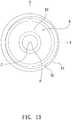
- the first ring 61 of the bearing 6 has a groove 76, a central axis P of which is not identical to a central axis C of the bearing 6, i.e., the first ring 61 is not concentric with the bearing 6.
- the screw bolt 53 of the transmission mechanism 51 is rotatably with the bearing 6, the first ring 61 of bearing 6 is non-circular, and the shape of the second positioning orifice 32 of the base 3 corresponds to the first ring 61 so as to avoid an idle rotation of the bearing 6 in the second positioning orifice 32 of the base 3 or a removal of the bearing 6 from the second positioning orifice 32.
- the piston 54 operates in the cylinder 4 smoothly, thus prolonging the service life of the air compressor 2.
Landscapes
- Engineering & Computer Science (AREA)
- General Engineering & Computer Science (AREA)
- Mechanical Engineering (AREA)
- Compressor (AREA)
- Compressors, Vaccum Pumps And Other Relevant Systems (AREA)
- Mounting Of Bearings Or Others (AREA)
- Rolling Contact Bearings (AREA)
Abstract
Description
- The present invention relates to a structure of fixing a bearing of an air compressor which avoids an idle rotation of the bearing in the base or a removal of the bearing from the second positioning orifice.
- With reference to
FIG. 14 , aconventional air compressor 1 for a vehicle contains: abase 11, acylinder 12 connected on thebase 11, a motor fixed on the base, and a piston driven by the motor to move in thecylinder 12 reciprocatingly, thus drawing, compressing, pressurizing, and discharging air out of the cylinder. - The motor is driven by a gear mechanism and a crank mechanism so as to actuate the piston to move. The gear mechanism includes a pinion fitted on a central shaft of the motor and a driven gear meshing with the pinion, a counterweight block of the crank mechanism is connected on the driven gear, and a connection post is rotatably connected with the piston. The
base 11 includes anorifice 110 configured to accommodate abearing 111 which is circular, and the connection post is eccentric with a shaft. When the driven gear is actuated by the pinion to rotate, the piston moves in thecylinder 12 reciprocatingly. - However, the
base 11 is made of plastic, so it is easy to be softened. The piston pulls thebearing 111 each other to cause deformation, and the piston offset greatly to damage theorifice 110, thus reducing a service life of the piston and thebearing 111. - The present invention has arisen to mitigate and/or obviate the afore-described disadvantages.
- The primary aspect of the present invention is to provide a structure of fixing a bearing of an air compressor which avoids an idle rotation of the bearing in the base or a removal of the bearing from the second positioning orifice.
- Another aspect of the present invention is to provide a structure of fixing a bearing of an air compressor in which the piston operates in the cylinder smoothly, thus prolonging a service life of the air compressor.
-
-
FIG. 1 is a perspective view showing the assembly of an air compressor according to a preferred embodiment of the present invention. -
FIG. 2 is a perspective view showing the exploded components of the air compressor according to the preferred embodiment of the present invention. -
FIG. 3 is a cross sectional view showing the assembly of the air compressor according to the preferred embodiment of the present invention. -
FIG. 4 is a cross-sectional perspective view showing the assembly of a part of a structure of fixing a bearing of an air compressor according to the preferred embodiment of the present invention. -
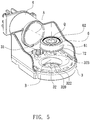
FIG. 5 is a cross-sectional perspective view showing the exploded components of a part of the structure of fixing the bearing of the air compressor according to the preferred embodiment of the present invention. -
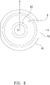
FIG. 6 is a side plan view showing the assembly of a part of a structure of fixing a bearing of an air compressor according to another preferred embodiment of the present invention. -
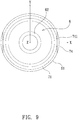
FIG. 7 is a side plan view showing the assembly of a part of a structure of fixing a bearing of an air compressor according to another preferred embodiment of the present invention. -
FIG. 8 is a perspective view showing the assembly of a part of a structure of fixing a bearing of an air compressor according to another preferred embodiment of the present invention. -
FIG. 9 is a side plan view ofFIG. 8 . -
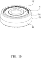
FIG. 10 is a perspective view showing the assembly of a part of a structure of fixing a bearing of an air compressor according to another preferred embodiment of the present invention. -
FIG. 11 is a perspective view showing the assembly of a part of a structure of fixing a bearing of an air compressor according to another preferred embodiment of the present invention. -
FIG. 12 is a side plan view ofFIG. 11 . -
FIG. 13 is a side plan view showing the assembly of a part of a structure of fixing a bearing of an air compressor according to another preferred embodiment of the present invention. -
FIG. 14 is a perspective view showing the exploded components of a conventional air compressor. - With reference to
FIGS. 1-3 , a structure of fixing abearing 6 of anair compressor 2 according to a preferred embodiment of the present invention, theair compressor 2 comprises: abase 3, acylinder 4 connected on thebase 3, amotor 5 and atransmission mechanism 51 which are connected with thebase 3. - The
base 3 includes multiple positioning orifices (i.e., afirst positioning orifice 31 and a second positioning orifice 32), wherein thefirst positioning orifice 31 accommodates apinion 50 on a core end of themotor 5, thesecond positioning orifice 32 accommodates thebearing 6, wherein thebearing 6 includes afirst ring 61, asecond ring 62, andmultiple balls 63 defined between thefirst ring 61 and thesecond ring 62, wherein thesecond positioning orifice 32 includes ashoulder 320 formed on a bottom thereof to avoid a removal of thebearing 6 from thesecond positioning orifice 32, and thesecond positioning orifice 32 includes a non-circular surroundingface 323 formed around a top thereof so that thebearing 6 is replaced onto thebase 3, a central axis A of thecylinder 4 is perpendicular to a longitudinal axis B extending from a center of thesecond positioning orifice 32 so as to produce an intersection point Q, as shown inFIG. 5 . In the meantime, apiston 54 of thecylinder 4 operates normally instead of eccentrically. The non-circular surroundingface 323 facilitates a removal of thebearing 6 from the central axis of thecylinder 4 so that the central axis A is not perpendicular to and is intersected with the longitudinal axis B so that thepiston 54 of thecylinder 4 operates eccentrically, thus not producing the intersection point Q. - The
cylinder 4 is integrally connected on thebase 3, and thecylinder 4 includes anair storage chamber 41 communicating therewith, wherein theair storage chamber 41 has anair outflow pipe 411 configured to output air, and theair storage chamber 41 has apressure gauge 412. - The
transmission mechanism 51 actuates thepiston 54 to move in thecylinder 4 reciprocatingly so as to produce compressed air, wherein thetransmission mechanism 51 is a gear integrally formed in a powder metallurgy manner and meshing with thepinion 50, wherein thetransmission mechanism 51 includes a threadedhole 510 defined on a center thereof and aconnection post 53 beside the threadedhole 510, wherein theconnection post 53 has anotch 530 defined around a distal end thereof away from the threadedhole 510. - Referring to
FIGS. 2-4 , thepiston 54 is rotatably connected with theconnection post 53 of thetransmission mechanism 51, alocking disc 531 is retained with thenotch 530 of theconnection post 53 to avoid a removal of thepiston 54 when thetransmission mechanism 51 operates. Thepiston 54 is accommodated into thecylinder 4, the threadedhole 510 of thetransmission mechanism 51 corresponds to thesecond ring 62 of thebearing 6 in thesecond positioning orifice 32 of thebase 3, and ascrew bolt 52 is inserted through thesecond ring 62 of thebearing 6 from thebase 3 to screw with the threadedhole 510. - As shown in
FIGS. 2-12 , thefirst ring 61 of thebearing 6 is non-circular, and a shape of thesecond positioning orifice 32 of thebase 3 corresponds to thefirst ring 61 so as to avoid an idle rotation of thebearing 6 in thesecond positioning orifice 32 of thebase 3 or a removal of thebearing 6 from thesecond positioning orifice 32. - As illustrated in
FIGS. 2-4 , thefirst ring 61 of thebearing 6 has aperipheral recess 71 retained with arib 321 of thesecond positioning orifice 32, such that thefirst ring 61 of thebearing 6 is locked, thebearing 6 does not remove when thetransmission mechanism 51 operates, and thepiston 54 operates in thecylinder 4 smoothly, thus prolonging a service life of theair compressor 2. - With reference to
FIG. 5 , in another embodiment, thering 61 of thebearing 6 has aprotrusion 72 retained with atrench 322 of thesecond positioning orifice 32 of thebase 3, such that thefirst ring 61 of thebearing 6 is locked, thebearing 6 does not remove when thetransmission mechanism 51 operates, and thepiston 54 operates in thecylinder 4 smoothly, thus prolonging the service life of theair compressor 2. - Referring to
FIG. 6 , in another embodiment, thefirst ring 61 of thebearing 6 has at least onetangent plane 73 formed on an X axis of a three-dimensional space. - As shown in
FIG. 7 , in another embodiment, thefirst ring 61 of thebearing 6 has a partialtangent plane 74 formed on an X axis of a three-dimensional space., i.e., thefirst ring 61 of thebearing 6 has at least oneplatform 741 formed on the X axis so that thebearing 6 does not rotate idly in or does not remove from thesecond positioning orifice 3, when thetransmission mechanism 51 operates. - As shown in
FIGS. 8-9 , in another embodiment, thefirst ring 61 of thebearing 6 has theperipheral recess 71 retained with therib 321, the partialtangent plane 74 and the at least oneplatform 741 which are formed on the X axis of a three-dimensional space. - As illustrated in
FIG. 10 , in another embodiment, thefirst ring 61 of thebearing 6 has aperipheral face 75 and abeveled face 751 extending from theperipheral face 75, wherein a diameter of thebeveled face 751 is less than theperipheral face 75 so that thebearing 6 does not remove from thesecond positioning orifice 32 of thebase 3, when thetransmission mechanism 51 operates. - With reference to
FIGS. 11-12 , in another embodiment, thefirst ring 61 of thebearing 6 has theperipheral face 75, thebeveled face 751, the partialtangent plane 74 and the at least oneplatform 741 which are formed on the X axis of the three-dimensional space. - Referring to
FIG. 13 , thefirst ring 61 of thebearing 6 has agroove 76, a central axis P of which is not identical to a central axis C of thebearing 6, i.e., thefirst ring 61 is not concentric with thebearing 6. - Accordingly, the
screw bolt 53 of thetransmission mechanism 51 is rotatably with thebearing 6, thefirst ring 61 ofbearing 6 is non-circular, and the shape of thesecond positioning orifice 32 of thebase 3 corresponds to thefirst ring 61 so as to avoid an idle rotation of thebearing 6 in thesecond positioning orifice 32 of thebase 3 or a removal of thebearing 6 from thesecond positioning orifice 32. Preferably, thepiston 54 operates in thecylinder 4 smoothly, thus prolonging the service life of theair compressor 2.
Claims (13)
- Air compressor with a structure for fixing a bearing (6) of the air compressor (2), comprising:a base (3) including multiple positioning orifices (31), (32), one of the multiple positioning orifices (31) accommodates a bearing (6);a cylinder (4) integrally connected with the base (3) and including an air storage chamber (41) communicating with the cylinder (4);a transmission mechanism (51) actuating a piston (54) to move in the cylinder (4) reciprocatingly so as to produce compressed air;wherein the first ring (61) of the bearing (6) is non-circular, and a shape of the one positioning orifice (32) of the base (3) corresponds to the first ring (61) so as to avoid an idle rotation of the bearing (6) in the one positioning orifice (32) of the base (3) or a removal of the bearing (6) from the second positioning orifice (32).
- Air compressor as claimed in claim 1, wherein the multiple positioning orifice (31), (32) are a first positioning orifice (31) and a second positioning orifice (32), wherein the first positioning orifice (31) accommodates a pinion (50) on a core end of the motor (5), and the second positioning orifice (32) accommodates the bearing (6), wherein the bearing (6) includes a first ring (61), a second ring (62), and multiple balls (63) defined between the first ring (61) and the second ring (62), wherein the second positioning orifice (32) includes a shoulder 320 formed on a bottom thereof to avoid a removal of the bearing (6) from the second positioning orifice (32), and the second positioning orifice (32) includes a non-circular surrounding face (323) formed around a top thereof so that the bearing (6) is replaced onto the base (3), a central axis (A) of the cylinder (4) is perpendicular to a longitudinal axis (B) extending from a center of the second positioning orifice (32) so as to produce an intersection point (Q), in the meantime, a piston (54) of the cylinder (4) operates normally, wherein the non-circular surrounding face (323) facilitates a removal of the bearing (6) from the central axis of the cylinder (4) so that the central axis (A) is not perpendicular to and is intersected with the longitudinal axis (B) so that the piston (54) of the cylinder (4) operates eccentrically, thus not producing the intersection point (Q).
- Air compressor as claimed in claim 1, wherein the transmission mechanism (51) includes a threaded hole (510) defined on a center thereof and a connection post (53) beside the threaded hole (510), the threaded hole (510) of the transmission mechanism (51) corresponds to the second ring (62) of the bearing (6) in the second positioning orifice (32) of the base (3), a screw bolt (52) is inserted through the second ring (62) of the bearing (6) from the base (3) to screw with the threaded hole (510), and the piston (54) is rotatably connected with the connection post (53) of the transmission mechanism (51).
- Air compressor as claimed in claim 3, wherein the transmission mechanism (51) is a gear integrally formed in a powder metallurgy manner and meshing with the pinion (50).
- Air compressor as claimed in claim 2, wherein the first ring (61) of the bearing (6) has a peripheral recess (71) retained with a rib (321) of the second positioning orifice (32), such that the first ring (61) of the bearing (6) is locked, the bearing (6) does not remove when the transmission mechanism (51) operates.
- Air compressor as claimed in claim 2, wherein the ring (61) of the bearing (6) has a protrusion (72) retained with a trench (322) of the second positioning orifice (32) of the base (3), such that the first ring (61) of the bearing (6) is locked, the bearing (6) does not remove when the transmission mechanism (51) operates.
- Air compressor as claimed in claim 2, wherein the first ring (61) of the bearing (6) has at least one tangent plane (73) formed on an X axis.
- Air compressor as claimed in claim 5, wherein the first ring (61) of the bearing (6) has a partial tangent plane (74) formed on an X axis, wherein the first ring (61) of the bearing (6) has at least one platform (741) formed on the X axis so that the bearing (6) does not rotate idly in or does not remove from the second positioning orifice (3), when the transmission mechanism (51) operates.
- Air compressor as claimed in claim 8, wherein the first ring (61) of the bearing (6) has the peripheral recess (71) retained with the rib (321), and the partial tangent plane (74) and the at least one platform (741) which are formed on the X axis.
- Air compressor as claimed in claim 8, wherein the first ring (61) of the bearing (6) has a peripheral face (75) and a beveled face (751) extending from the peripheral face (75), wherein a diameter of the beveled face (751) is less than the peripheral face (75) so that the bearing (6) does not remove from the second positioning orifice (32) of the base (3), when the transmission mechanism (51) operates.
- Air compressor as claimed in claim 10, wherein the first ring (61) of the bearing (6) has the peripheral face (75), the beveled face (751), the partial tangent plane (74) and the at least one platform (741) which are formed on the X axis.
- Air compressor as claimed in claim 5, wherein the first ring (61) of the bearing (6) has a groove (76), a central axis P of which is not identical to a central axis C of the bearing (6), and the first ring (61) is not concentric with the bearing (6).
- Air compressor as claimed in claim 1, wherein the piston (54) is rotatably connected with a connection post (53) of the transmission mechanism (51), a locking disc (531) is retained with a notch (530) of the connection post (53) to avoid a removal of the piston (54), when the transmission mechanism (51) operates.
Priority Applications (1)
| Application Number | Priority Date | Filing Date | Title |
|---|---|---|---|
| PL19190880T PL3608540T3 (en) | 2018-08-09 | 2019-08-08 | Structure of fixing bearing of air compressor |
Applications Claiming Priority (1)
| Application Number | Priority Date | Filing Date | Title |
|---|---|---|---|
| TW107127890A TWI687602B (en) | 2018-08-09 | 2018-08-09 | Structure of fixing bearing of air compressor |
Publications (2)
| Publication Number | Publication Date |
|---|---|
| EP3608540A1 true EP3608540A1 (en) | 2020-02-12 |
| EP3608540B1 EP3608540B1 (en) | 2021-05-19 |
Family
ID=67587565
Family Applications (1)
| Application Number | Title | Priority Date | Filing Date |
|---|---|---|---|
| EP19190880.5A Active EP3608540B1 (en) | 2018-08-09 | 2019-08-08 | Structure of fixing bearing of air compressor |
Country Status (10)
| Country | Link |
|---|---|
| US (1) | US10914298B2 (en) |
| EP (1) | EP3608540B1 (en) |
| JP (2) | JP6876756B2 (en) |
| KR (1) | KR102140475B1 (en) |
| CN (2) | CN210859103U (en) |
| DE (1) | DE202019104170U1 (en) |
| DK (1) | DK3608540T3 (en) |
| HU (1) | HUE055847T2 (en) |
| PL (1) | PL3608540T3 (en) |
| TW (1) | TWI687602B (en) |
Cited By (1)
| Publication number | Priority date | Publication date | Assignee | Title |
|---|---|---|---|---|
| EP3628865B1 (en) * | 2018-09-28 | 2022-06-08 | UNIK World Industrial Co., Ltd. | Air compressor |
Families Citing this family (5)
| Publication number | Priority date | Publication date | Assignee | Title |
|---|---|---|---|---|
| TWI676509B (en) * | 2017-11-30 | 2019-11-11 | 已久工業股份有限公司 | Method and structure for mounting a bearing to an air compressor |
| TWI698581B (en) * | 2018-12-14 | 2020-07-11 | 周文三 | Conenction structure for motor of air compressor |
| TWI691649B (en) * | 2018-12-17 | 2020-04-21 | 周文三 | Positioning structure of motor of air compressor |
| CN114483527B (en) * | 2020-10-27 | 2024-05-24 | 莱克电气股份有限公司 | Inflator pump that conveniently carries |
| CN115217744B (en) * | 2022-07-08 | 2023-10-27 | 合肥通用机械研究院有限公司 | Oil-free compressor transmission device and piston ring optimal design method thereof |
Citations (4)
| Publication number | Priority date | Publication date | Assignee | Title |
|---|---|---|---|---|
| US20040105766A1 (en) * | 2002-01-25 | 2004-06-03 | Chou Wen San | Air compressor having stable configuration |
| EP2187073A1 (en) * | 2007-08-31 | 2010-05-19 | JTEKT Corporation | Bearing structure, and its manufacturing method |
| DE202015101980U1 (en) * | 2014-04-22 | 2015-05-05 | Wen-San Chou | Compressor with reduced weight |
| EP3258572A1 (en) * | 2014-08-21 | 2017-12-20 | Jiangxi Gongbu Machinery Co., Ltd. | Low speed and high torque electric motor outer rotor, electric motor and related crane |
Family Cites Families (16)
| Publication number | Priority date | Publication date | Assignee | Title |
|---|---|---|---|---|
| US6280163B1 (en) * | 1998-03-30 | 2001-08-28 | Wen San Chou | Spring blade intake valve for air compressor |
| ITTO20010604A1 (en) * | 2001-06-22 | 2002-12-22 | Sistemi Sospensioni Spa | ASSEMBLING THE BEARING FOR A WHEEL HUB ON A SUSPENSION OF A VEHICLE. |
| JP2005220957A (en) * | 2004-02-04 | 2005-08-18 | Nsk Ltd | Pulley device |
| JP2006077881A (en) * | 2004-09-09 | 2006-03-23 | Nsk Ltd | Creep preventing rolling bearing and creep preventing rolling bearing device |
| TWM276750U (en) * | 2005-02-23 | 2005-10-01 | Jiun-Jian Liau | Two-way vehicular burglar monitoring system using wireless cellphone |
| JP2007162870A (en) * | 2005-12-15 | 2007-06-28 | Nsk Ltd | Creep-preventive bearing |
| JP2009270644A (en) * | 2008-05-08 | 2009-11-19 | Ntn Corp | Resin pulley device |
| FR2932863B1 (en) * | 2008-06-23 | 2010-12-10 | Skf Ab | PULLEY DEVICE FOR TENDER ROLLER OR ROLLER. |
| US20130078119A1 (en) * | 2011-09-28 | 2013-03-28 | Wen San Chou | Bearing arrangement for air compressor |
| JP3173160U (en) * | 2011-11-09 | 2012-01-26 | 文三 周 | Compressor transmission mechanism |
| US20160082677A1 (en) * | 2014-09-24 | 2016-03-24 | Illinois Tool Works Inc. | Device for delivering a medium |
| TWI591257B (en) * | 2014-05-15 | 2017-07-11 | 周文三 | Rotating mechanism of an air compressor |
| CN104158325B (en) * | 2014-08-21 | 2017-06-27 | 江西工埠机械有限责任公司 | The permanent magnetism mounting structure of external rotor electric machine |
| TWI579460B (en) * | 2014-10-08 | 2017-04-21 | Wen-San Jhou | Improved air compressor |
| TWI589776B (en) * | 2015-03-11 | 2017-07-01 | 周文三 | Inflator kit |
| TWI617741B (en) * | 2016-01-14 | 2018-03-11 | 周文三 | Improved air compressor |
-
2018
- 2018-08-09 TW TW107127890A patent/TWI687602B/en active
-
2019
- 2019-07-24 KR KR1020190089499A patent/KR102140475B1/en active IP Right Grant
- 2019-07-29 DE DE202019104170.6U patent/DE202019104170U1/en active Active
- 2019-08-07 US US16/534,500 patent/US10914298B2/en active Active
- 2019-08-08 DK DK19190880.5T patent/DK3608540T3/en active
- 2019-08-08 HU HUE19190880A patent/HUE055847T2/en unknown
- 2019-08-08 PL PL19190880T patent/PL3608540T3/en unknown
- 2019-08-08 CN CN201921278839.6U patent/CN210859103U/en not_active Expired - Fee Related
- 2019-08-08 EP EP19190880.5A patent/EP3608540B1/en active Active
- 2019-08-08 JP JP2019145951A patent/JP6876756B2/en active Active
- 2019-08-08 CN CN201910729948.3A patent/CN110821784B/en active Active
- 2019-08-08 JP JP2019002974U patent/JP3223595U/en active Active
Patent Citations (4)
| Publication number | Priority date | Publication date | Assignee | Title |
|---|---|---|---|---|
| US20040105766A1 (en) * | 2002-01-25 | 2004-06-03 | Chou Wen San | Air compressor having stable configuration |
| EP2187073A1 (en) * | 2007-08-31 | 2010-05-19 | JTEKT Corporation | Bearing structure, and its manufacturing method |
| DE202015101980U1 (en) * | 2014-04-22 | 2015-05-05 | Wen-San Chou | Compressor with reduced weight |
| EP3258572A1 (en) * | 2014-08-21 | 2017-12-20 | Jiangxi Gongbu Machinery Co., Ltd. | Low speed and high torque electric motor outer rotor, electric motor and related crane |
Cited By (1)
| Publication number | Priority date | Publication date | Assignee | Title |
|---|---|---|---|---|
| EP3628865B1 (en) * | 2018-09-28 | 2022-06-08 | UNIK World Industrial Co., Ltd. | Air compressor |
Also Published As
| Publication number | Publication date |
|---|---|
| CN110821784B (en) | 2021-09-28 |
| JP2020026795A (en) | 2020-02-20 |
| CN210859103U (en) | 2020-06-26 |
| JP3223595U (en) | 2019-10-17 |
| US20200049138A1 (en) | 2020-02-13 |
| KR102140475B1 (en) | 2020-08-04 |
| US10914298B2 (en) | 2021-02-09 |
| DE202019104170U1 (en) | 2019-08-06 |
| TWI687602B (en) | 2020-03-11 |
| EP3608540B1 (en) | 2021-05-19 |
| KR20200018251A (en) | 2020-02-19 |
| PL3608540T3 (en) | 2021-11-22 |
| TW202009392A (en) | 2020-03-01 |
| CN110821784A (en) | 2020-02-21 |
| JP6876756B2 (en) | 2021-05-26 |
| HUE055847T2 (en) | 2021-12-28 |
| DK3608540T3 (en) | 2021-08-23 |
Similar Documents
| Publication | Publication Date | Title |
|---|---|---|
| EP3608540A1 (en) | Structure of fixing bearing of air compressor | |
| EP3667084B1 (en) | Conenction structure for motor of air compressor | |
| EP3628865A1 (en) | Air compressor | |
| EP2944816B1 (en) | Air compressor with improved rotating device | |
| US9803632B2 (en) | Air compressor of weight-reduction type | |
| US20210262524A1 (en) | Method of mounting a bearing to an air compressor, and air compressor having a bearing mounted by the method | |
| KR20200075748A (en) | Structure for engaging and positioning the motor in air compressor | |
| EP3628869B1 (en) | Transmission mechanism of air compressor | |
| JP2020016238A (en) | Pump module and high-pressure washing machine | |
| JP2018091338A (en) | Air compressor motor position setting structure | |
| US7168856B1 (en) | Wet cup throat seal and bearing assembly | |
| JP2605945B2 (en) | Oil pump manufacturing method | |
| TWM586750U (en) | Motor combination positioning structure of air compressor |
Legal Events
| Date | Code | Title | Description |
|---|---|---|---|
| PUAI | Public reference made under article 153(3) epc to a published international application that has entered the european phase |
Free format text: ORIGINAL CODE: 0009012 |
|
| STAA | Information on the status of an ep patent application or granted ep patent |
Free format text: STATUS: REQUEST FOR EXAMINATION WAS MADE |
|
| 17P | Request for examination filed |
Effective date: 20191023 |
|
| AK | Designated contracting states |
Kind code of ref document: A1 Designated state(s): AL AT BE BG CH CY CZ DE DK EE ES FI FR GB GR HR HU IE IS IT LI LT LU LV MC MK MT NL NO PL PT RO RS SE SI SK SM TR |
|
| AX | Request for extension of the european patent |
Extension state: BA ME |
|
| GRAP | Despatch of communication of intention to grant a patent |
Free format text: ORIGINAL CODE: EPIDOSNIGR1 |
|
| STAA | Information on the status of an ep patent application or granted ep patent |
Free format text: STATUS: GRANT OF PATENT IS INTENDED |
|
| RIC1 | Information provided on ipc code assigned before grant |
Ipc: F04B 39/00 20060101ALI20201106BHEP Ipc: F04B 35/00 20060101AFI20201106BHEP |
|
| INTG | Intention to grant announced |
Effective date: 20201201 |
|
| GRAS | Grant fee paid |
Free format text: ORIGINAL CODE: EPIDOSNIGR3 |
|
| GRAA | (expected) grant |
Free format text: ORIGINAL CODE: 0009210 |
|
| STAA | Information on the status of an ep patent application or granted ep patent |
Free format text: STATUS: THE PATENT HAS BEEN GRANTED |
|
| AK | Designated contracting states |
Kind code of ref document: B1 Designated state(s): AL AT BE BG CH CY CZ DE DK EE ES FI FR GB GR HR HU IE IS IT LI LT LU LV MC MK MT NL NO PL PT RO RS SE SI SK SM TR |
|
| REG | Reference to a national code |
Ref country code: GB Ref legal event code: FG4D |
|
| REG | Reference to a national code |
Ref country code: CH Ref legal event code: EP |
|
| REG | Reference to a national code |
Ref country code: DE Ref legal event code: R096 Ref document number: 602019004686 Country of ref document: DE |
|
| REG | Reference to a national code |
Ref country code: AT Ref legal event code: REF Ref document number: 1394226 Country of ref document: AT Kind code of ref document: T Effective date: 20210615 |
|
| REG | Reference to a national code |
Ref country code: IE Ref legal event code: FG4D |
|
| REG | Reference to a national code |
Ref country code: DK Ref legal event code: T3 Effective date: 20210817 |
|
| REG | Reference to a national code |
Ref country code: NL Ref legal event code: FP |
|
| REG | Reference to a national code |
Ref country code: LT Ref legal event code: MG9D |
|
| REG | Reference to a national code |
Ref country code: SE Ref legal event code: TRGR |
|
| PG25 | Lapsed in a contracting state [announced via postgrant information from national office to epo] |
Ref country code: BG Free format text: LAPSE BECAUSE OF FAILURE TO SUBMIT A TRANSLATION OF THE DESCRIPTION OR TO PAY THE FEE WITHIN THE PRESCRIBED TIME-LIMIT Effective date: 20210819 Ref country code: FI Free format text: LAPSE BECAUSE OF FAILURE TO SUBMIT A TRANSLATION OF THE DESCRIPTION OR TO PAY THE FEE WITHIN THE PRESCRIBED TIME-LIMIT Effective date: 20210519 Ref country code: HR Free format text: LAPSE BECAUSE OF FAILURE TO SUBMIT A TRANSLATION OF THE DESCRIPTION OR TO PAY THE FEE WITHIN THE PRESCRIBED TIME-LIMIT Effective date: 20210519 Ref country code: LT Free format text: LAPSE BECAUSE OF FAILURE TO SUBMIT A TRANSLATION OF THE DESCRIPTION OR TO PAY THE FEE WITHIN THE PRESCRIBED TIME-LIMIT Effective date: 20210519 |
|
| PG25 | Lapsed in a contracting state [announced via postgrant information from national office to epo] |
Ref country code: NO Free format text: LAPSE BECAUSE OF FAILURE TO SUBMIT A TRANSLATION OF THE DESCRIPTION OR TO PAY THE FEE WITHIN THE PRESCRIBED TIME-LIMIT Effective date: 20210819 Ref country code: LV Free format text: LAPSE BECAUSE OF FAILURE TO SUBMIT A TRANSLATION OF THE DESCRIPTION OR TO PAY THE FEE WITHIN THE PRESCRIBED TIME-LIMIT Effective date: 20210519 Ref country code: PT Free format text: LAPSE BECAUSE OF FAILURE TO SUBMIT A TRANSLATION OF THE DESCRIPTION OR TO PAY THE FEE WITHIN THE PRESCRIBED TIME-LIMIT Effective date: 20210920 Ref country code: RS Free format text: LAPSE BECAUSE OF FAILURE TO SUBMIT A TRANSLATION OF THE DESCRIPTION OR TO PAY THE FEE WITHIN THE PRESCRIBED TIME-LIMIT Effective date: 20210519 Ref country code: GR Free format text: LAPSE BECAUSE OF FAILURE TO SUBMIT A TRANSLATION OF THE DESCRIPTION OR TO PAY THE FEE WITHIN THE PRESCRIBED TIME-LIMIT Effective date: 20210820 Ref country code: IS Free format text: LAPSE BECAUSE OF FAILURE TO SUBMIT A TRANSLATION OF THE DESCRIPTION OR TO PAY THE FEE WITHIN THE PRESCRIBED TIME-LIMIT Effective date: 20210919 |
|
| REG | Reference to a national code |
Ref country code: HU Ref legal event code: AG4A Ref document number: E055847 Country of ref document: HU |
|
| PG25 | Lapsed in a contracting state [announced via postgrant information from national office to epo] |
Ref country code: SK Free format text: LAPSE BECAUSE OF FAILURE TO SUBMIT A TRANSLATION OF THE DESCRIPTION OR TO PAY THE FEE WITHIN THE PRESCRIBED TIME-LIMIT Effective date: 20210519 Ref country code: ES Free format text: LAPSE BECAUSE OF FAILURE TO SUBMIT A TRANSLATION OF THE DESCRIPTION OR TO PAY THE FEE WITHIN THE PRESCRIBED TIME-LIMIT Effective date: 20210519 Ref country code: EE Free format text: LAPSE BECAUSE OF FAILURE TO SUBMIT A TRANSLATION OF THE DESCRIPTION OR TO PAY THE FEE WITHIN THE PRESCRIBED TIME-LIMIT Effective date: 20210519 Ref country code: RO Free format text: LAPSE BECAUSE OF FAILURE TO SUBMIT A TRANSLATION OF THE DESCRIPTION OR TO PAY THE FEE WITHIN THE PRESCRIBED TIME-LIMIT Effective date: 20210519 Ref country code: SM Free format text: LAPSE BECAUSE OF FAILURE TO SUBMIT A TRANSLATION OF THE DESCRIPTION OR TO PAY THE FEE WITHIN THE PRESCRIBED TIME-LIMIT Effective date: 20210519 |
|
| REG | Reference to a national code |
Ref country code: DE Ref legal event code: R097 Ref document number: 602019004686 Country of ref document: DE |
|
| PLBE | No opposition filed within time limit |
Free format text: ORIGINAL CODE: 0009261 |
|
| STAA | Information on the status of an ep patent application or granted ep patent |
Free format text: STATUS: NO OPPOSITION FILED WITHIN TIME LIMIT |
|
| PG25 | Lapsed in a contracting state [announced via postgrant information from national office to epo] |
Ref country code: MC Free format text: LAPSE BECAUSE OF FAILURE TO SUBMIT A TRANSLATION OF THE DESCRIPTION OR TO PAY THE FEE WITHIN THE PRESCRIBED TIME-LIMIT Effective date: 20210519 |
|
| 26N | No opposition filed |
Effective date: 20220222 |
|
| PG25 | Lapsed in a contracting state [announced via postgrant information from national office to epo] |
Ref country code: IS Free format text: LAPSE BECAUSE OF FAILURE TO SUBMIT A TRANSLATION OF THE DESCRIPTION OR TO PAY THE FEE WITHIN THE PRESCRIBED TIME-LIMIT Effective date: 20210919 Ref country code: LU Free format text: LAPSE BECAUSE OF NON-PAYMENT OF DUE FEES Effective date: 20210808 Ref country code: AL Free format text: LAPSE BECAUSE OF FAILURE TO SUBMIT A TRANSLATION OF THE DESCRIPTION OR TO PAY THE FEE WITHIN THE PRESCRIBED TIME-LIMIT Effective date: 20210519 |
|
| PG25 | Lapsed in a contracting state [announced via postgrant information from national office to epo] |
Ref country code: IE Free format text: LAPSE BECAUSE OF NON-PAYMENT OF DUE FEES Effective date: 20210808 |
|
| PGFP | Annual fee paid to national office [announced via postgrant information from national office to epo] |
Ref country code: NL Payment date: 20220822 Year of fee payment: 4 |
|
| PGFP | Annual fee paid to national office [announced via postgrant information from national office to epo] |
Ref country code: TR Payment date: 20220803 Year of fee payment: 4 Ref country code: SE Payment date: 20220824 Year of fee payment: 4 Ref country code: IT Payment date: 20220831 Year of fee payment: 4 Ref country code: DK Payment date: 20220824 Year of fee payment: 4 Ref country code: CZ Payment date: 20220711 Year of fee payment: 4 |
|
| PGFP | Annual fee paid to national office [announced via postgrant information from national office to epo] |
Ref country code: PL Payment date: 20220712 Year of fee payment: 4 Ref country code: HU Payment date: 20220726 Year of fee payment: 4 Ref country code: FR Payment date: 20220822 Year of fee payment: 4 Ref country code: BE Payment date: 20220822 Year of fee payment: 4 |
|
| REG | Reference to a national code |
Ref country code: AT Ref legal event code: UEP Ref document number: 1394226 Country of ref document: AT Kind code of ref document: T Effective date: 20210519 |
|
| REG | Reference to a national code |
Ref country code: CH Ref legal event code: PL |
|
| PG25 | Lapsed in a contracting state [announced via postgrant information from national office to epo] |
Ref country code: LI Free format text: LAPSE BECAUSE OF NON-PAYMENT OF DUE FEES Effective date: 20220831 Ref country code: CH Free format text: LAPSE BECAUSE OF NON-PAYMENT OF DUE FEES Effective date: 20220831 |
|
| P01 | Opt-out of the competence of the unified patent court (upc) registered |
Effective date: 20230523 |
|
| PG25 | Lapsed in a contracting state [announced via postgrant information from national office to epo] |
Ref country code: CY Free format text: LAPSE BECAUSE OF FAILURE TO SUBMIT A TRANSLATION OF THE DESCRIPTION OR TO PAY THE FEE WITHIN THE PRESCRIBED TIME-LIMIT Effective date: 20210519 |
|
| PGFP | Annual fee paid to national office [announced via postgrant information from national office to epo] |
Ref country code: DE Payment date: 20230818 Year of fee payment: 5 |
|
| REG | Reference to a national code |
Ref country code: DK Ref legal event code: EBP Effective date: 20230831 |
|
| REG | Reference to a national code |
Ref country code: NL Ref legal event code: MM Effective date: 20230901 |
|
| GBPC | Gb: european patent ceased through non-payment of renewal fee |
Effective date: 20230808 |
|
| PG25 | Lapsed in a contracting state [announced via postgrant information from national office to epo] |
Ref country code: MK Free format text: LAPSE BECAUSE OF FAILURE TO SUBMIT A TRANSLATION OF THE DESCRIPTION OR TO PAY THE FEE WITHIN THE PRESCRIBED TIME-LIMIT Effective date: 20210519 Ref country code: HU Free format text: LAPSE BECAUSE OF NON-PAYMENT OF DUE FEES Effective date: 20230809 Ref country code: CZ Free format text: LAPSE BECAUSE OF NON-PAYMENT OF DUE FEES Effective date: 20230808 |
|
| REG | Reference to a national code |
Ref country code: BE Ref legal event code: MM Effective date: 20230831 |
|
| PG25 | Lapsed in a contracting state [announced via postgrant information from national office to epo] |
Ref country code: NL Free format text: LAPSE BECAUSE OF NON-PAYMENT OF DUE FEES Effective date: 20230901 |