EP3608287A1 - Capping machine and operating method thereof - Google Patents
Capping machine and operating method thereof Download PDFInfo
- Publication number
- EP3608287A1 EP3608287A1 EP18306084.7A EP18306084A EP3608287A1 EP 3608287 A1 EP3608287 A1 EP 3608287A1 EP 18306084 A EP18306084 A EP 18306084A EP 3608287 A1 EP3608287 A1 EP 3608287A1
- Authority
- EP
- European Patent Office
- Prior art keywords
- cap
- gripping device
- carts
- stretch
- capping machine
- Prior art date
- Legal status (The legal status is an assumption and is not a legal conclusion. Google has not performed a legal analysis and makes no representation as to the accuracy of the status listed.)
- Granted
Links
Images



Classifications
-
- B—PERFORMING OPERATIONS; TRANSPORTING
- B67—OPENING, CLOSING OR CLEANING BOTTLES, JARS OR SIMILAR CONTAINERS; LIQUID HANDLING
- B67B—APPLYING CLOSURE MEMBERS TO BOTTLES JARS, OR SIMILAR CONTAINERS; OPENING CLOSED CONTAINERS
- B67B3/00—Closing bottles, jars or similar containers by applying caps
- B67B3/20—Closing bottles, jars or similar containers by applying caps by applying and rotating preformed threaded caps
- B67B3/204—Linear-type capping machines
- B67B3/2046—Linear-type capping machines using friction means for screwing the caps, e.g. belts or wheels
Definitions
- the present invention is relative to a capping machine and to an operating method thereof.
- the filled containers are generally closed in an automated manner by means of specific capping machines.
- Known capping machines normally comprise a horizontal rotating carousel that defines a plurality of peripheral seats for housing and retaining the containers, and a screwing unit consisting of a corresponding plurality of gripping devices that are driven in rotation by the carousel and are respectively vertically aligned with the seats.
- the screwing devices carry respective caps and enforce a screw motion of the caps about the respective necks of the containers.
- each screwing device is vertically movable along the axis of the corresponding neck and is adapted to apply a screwing torque on the corresponding cap.
- the containers and the caps are fed to the capping machine through transport means such as star wheels and/or linear conveyors; similarly, the closed containers are drawn from the capping machine through further analogous transport means.
- capping machines are scarcely satisfactory from the point of view of the use flexibility.
- capping machines are typically compatible with only one kind of caps and one kind of containers.
- An additional need is to provide a capping machine that is more compact and occupies less space than the known rotary machines.
- numeral 1 indicates, as a whole, a capping machine, in particular for applying internally threaded round caps 2 on product containers, e.g. bottles 3 containing for example pourable liquid products.
- Bottles 3 are fed to the capping machine already filled with a predetermined quantity of product, and may be made for instance of a plastic material or glass.
- bottles 3 are filled with a food product such as milk, fruit juice, wine, coke, etc.
- bottles 3 may be filled with industrial or cosmetic products like lubricant oil, liquid soap, detergents, etc.
- each bottle 3 is defined by an elongated cylindrical-like body ( Figure 2 , 3 and 5 ) that has a lateral wall 4 and extends parallel to a vertical direction Y from a base 5 to a neck 6, which is opposite to the base 5; in particular, the lateral wall 4 has an upper portion tapering to the neck 6, which has a diameter lower than that of the base 5.
- Each neck 6 has a lower cylindrical portion 6a ( Figure 5 ) joined to the lateral wall 4 and an upper cylindrical portion 6b having the same diameter as the one of portion 6a and being externally threaded.
- each cap 2 is suitable for being screwed onto one corresponding threaded portion 6b according to a direction parallel to direction Y.
- each cap 2 is defined by a disk-shaped end wall 2a and a by cylindrical lateral wall 2b protruding orthogonally from the outer profile of the end wall 2a and on one side only thereof.
- the lateral wall 2b is internally threaded and is axially delimited between the end wall 2a to a free circular edge 2c.
- capping machine 1 comprises:
- the path Q extends parallel to a horizontal direction X and, therefore, is rectilinear.
- the conveyor apparatus 8 comprises a first conveyor member 11 that extends along a feeding stretch Q1 of the path Q, arranged upstream of the capping stretch Q2 with reference to the moving direction of the bottles 3.
- the first conveyor member 11 comprises a lower conveyor belt 12 ( Figure 2 ) supporting the bases 5 of the bottles 3 to drive the latter along the stretch Q1, and a pair of upper passive belts 13 arranged at respective lateral sides of conveyor belt 12 and cooperating in contact with lateral walls 4 of bottles 3, so as to prevent lateral displacements of the bottles 3 themselves.
- passive belts 13 prevent also rotations of the bottles 3 around their respective axes A, so that bottles 3 are fed to conveyor belt 12 with a controlled and predetermined orientation that does not change during the travel of the bottles 3 along the stretch Q1.
- the conveyor apparatus 8 comprises a second conveyor member 14 extending along the stretch Q2 and preferably comprising a couple of endless tracks 16a, 16b (partially illustrated) having respective branches or portions 17a, 17b that extend parallel to stretch Q2 and are respectively aligned substantially with passive belts 13.
- the second conveyor member 14 further comprises a plurality of bottle handling devices 18 ( Figure 3 ), each of which is adapted to clamp and hold portion 6a of neck 6 of one bottle 3 by means of two jaws 18a, 18b that respectively make part of two carts 19a, 19b coupled in a sliding manner to tracks 16a, 16b.
- each track 16a, 16b houses a stator armature 22 ( Figure 5 ) formed by a plurality of individually excitable solenoids, whilst carts 19a, 19b house respective permanent magnets (not shown) moving relatively to tracks 16a, 16b, in reply to current supplied to the solenoids.
- the tracks 16a, 16b are converging between each other such that carts 19a, 19b confer to respective jaws 18a, 18b a clamping movement that terminates exactly at the beginning of the stretch Q2.
- the bottles 3 are supplied by the first conveyor member 11 to respective devices 18 at the end of the stretch Q1 (i.e. at the beginning of the stretch Q2), where jaws 18a, 18b clamp the portion 6a of neck 6 of one respective bottle 3.
- each bottle 3 is driven at the velocity V2 through the jaws 18a, 18b along the stretch Q2. Thanks to the jaws 18a, 18b, each bottle 3 maintains its own orientation during the clamping and the transport phase along the stretch Q2.
- the conveyor apparatus 8 also comprises a third conveyor member 20 extending along a delivery stretch Q3 of the path Q, downstream of the stretch Q2 with reference to the moving direction of the bottles 3.
- the tracks 16a, 16b start to diverge between each other such that the jaws 18a, 18b release the bottles 3 onto a conveyor belt 21 of the third conveyor member 20.
- the third conveyor member 20 receives bottles 3 that are already closed by caps 2. Moreover, the conveyor member 20 is constructively similar to the conveyor member 11, so it is not described in further detail.
- cap screwing unit 9 comprises a plurality of gripping devices 25 configured to screw respective caps 2 onto the bottles 3.
- Each gripping device 25 receives a corresponding cap 2 at a station I and moves parallel to direction X along a path P.
- Path P extends downstream of the station I and is aligned above the capping stretch Q2 of path Q.
- Cap screwing unit 9 further comprises an infeed assembly 26 ( Figures 1 and 2 ) for feeding the caps 2 to the gripping devices 25 at the station I.
- the incoming cap 2 at the station I has its axis parallel to direction Y.
- the end wall 2a of each cap 2 is horizontally oriented and the lateral wall 2b extends downward from the end wall 2a.
- the infeed assembly 26 comprises, in particular, a conveyor, preferably defined by a chute 28 ( Figure 2 ), for advancing caps 2 toward station I. Moreover, the infeed assembly 26 further comprises a stop device 33 for stopping the caps 2 downstream of the chute 28. In particular, the caps 2 rest onto the chute 28 with the edges 2c in contact with the chute 28.
- the infeed assembly 26 comprises two facing lateral belts 34, frictionally interacting with lateral walls 2b of caps 2 and independently drivable with different velocities.
- the belts 34 guide the caps 2 toward the station I.
- the belts 34 contextually impose a predetermined orientation to caps 2 while feeding the latter to the gripping devices 25.
- cap screwing unit 9 further comprises two endless tracks 38a, 38b that are arranged on respective opposite lateral sides of the screwing stretch of path P and have at least respective rectilinear branches or portions 39a, 39b extending parallel and close to the path P itself.
- branches 39a, 39b extend at respective opposite lateral sides of the path P according to a direction Z, which is orthogonal to both directions X, Y. More specifically, the branches 39a, 39b are equally spaced from the path P along direction Z, so as to leave enough clearance for moving the gripping devices 25 therebetween.
- the endless tracks 38a, 38b extend along respective elliptical paths R1, R2 having the same geometric and dimensional properties.
- Paths R1, R2 are both arranged on an ideal horizontal plane including the path P, in particular in symmetric mirrored positions with respect to the latter path P.
- paths R1, R2 may be also arranged on parallel vertical planes placed on both sides of path P.
- cap screwing unit 9 comprises a fist and a second plurality of carts 25a, 25b respectively coupled to tracks 38a, 38b in a sliding manner, such that carts 25a are relatively movable with respect to carts 25b.
- One cart 25a and one cart 25b make part of one corresponding gripping device 25 when both carts 25a, 25b move along the respective branches 39a, 39b.
- the carts 25a, 25b of one gripping device 25 have at least respective portions that are facing each other along the direction Z.
- two carts 25a, 25b define one corresponding gripping device 25.
- all carts 25a and all carts 25b are self-movable and respectively move along the corresponding tracks 38a, 38b independently of each other.
- carts 25a, 25b are movable along tracks 38a, 38b exactly in the same manner as carts 19a, 19b move along tracks 16a, 16b.
- tracks 38a, 38b house respective armatures 22, whilst carts 25a, 25b house respective permanent magnets like carts 19.
- the corresponding carts 25a, 25b define together a housing or seat 40 having a dimension along direction Z such that the same housing 40 is suitable to be engaged by a cap 2 in a sliding manner along direction X.
- carts 25a, 25b have respective recesses 40a, 40b, that form the housing 40 and preferably have the same depth along direction Z. More specifically, both recesses 40a, 40b are delimited in depth along direction Z by respective vertical surfaces 41a, 41b ( Figures 3 , 4 ).
- Vertical surfaces 41a, 41b comes in sliding contact with the lateral wall 2b of a cap 2 when the respective gripping device 25 receives such cap 2.
- surfaces 41a, 41b are textured, conveniently with the same texture of the lateral wall 2b of the respective cap 2, in order to increase friction between surfaces 41a, 41b and the lateral wall 2b itself. In this way, surfaces 41a, 41b allow a controlled sliding of the cap 2 engaged therebetween.
- recesses 40a, 40b are upwardly delimited by respective contoured surfaces 42a, 42b that are adapted to come in sliding contact with the end wall 2a of a cap 2 when the gripping device 25 receives such cap 2.
- the received cap 2 engages both the recesses 40a, 40b maintaining the orientation that the same cap 2 already had at the station I.
- Contoured surfaces 42a, 42b define respective cams that are ramp-shaped to guide the movement of the received cap 2 along direction Y.
- the contoured surfaces 42a, 42b are respectively defined by two ramp-shaped cam profiles extending planarly along the direction Z from the corresponding surfaces 41a, 41b. Therefore, the contoured surfaces 42a, 42b intersect the respective surfaces 41a, 41b forming such cam profiles.
- the above cam profiles have respective opposite vertical developments with respect to the horizontal moving direction of the bottles 3, i.e. to the direction X.
- the cam profiles are mirror-symmetrical to each other with respect to an ideal plane extending along the moving direction of the bottles 3 or caps 2, i.e. stretch Q2 or path P.
- contoured surfaces 42a are defined by declining ramps in the moving direction of the carts 25a along path P; in a different manner, contoured surfaces 42b are defined by climbing ramps in the moving direction of the carts 25b along path P.
- the mutual position of the carts 25a, 25b is such that the portions of the contoured surfaces 42a, 42b in contact with the end wall 2a are at the same height level.
- the screw motion is obtained by moving the carts 25a, 25b relatively to one another.
- the movement of the cap 2 is obtained by controlling/changing the speed of the carts 25a, 25b. More precisely, the received cap 2 has a screw motion parallel to direction Y once the carts 25a, 25b are moved at different speeds.
- the variation in the mutual position along direction X between the carts 25a, 25b imparts a rotary motion to the cap 2, which, as a result of the engagement between the internal thread of lateral wall 2b of the cap 2 itself and the threaded portion 6b of the neck 6 of the respective bottle 3, results in a helical movement of such cap 2 along an axis parallel to direction Y.
- the relative motion between carts 25a, 25b causes the corresponding surfaces 41a, 41b to exert respective friction forces on the lateral wall 2a of the cap 2 held by the respective gripping device 25.
- the cap 2 receives a torque causing the rolling of the cap 2 onto both surfaces 41a, 41b. Accordingly, while the cap 2 translates relatively to the surfaces 41a, 41b, the contoured surfaces 42a, 42b guide the downward motion of the cap 2 along direction Y.
- cap screwing unit 9 further comprises a sensor system SS having a plurality of transducers configured to:
- the transducers may be partly selected from the group of optical position sensors, like for instance linear or angular encoders (in particular coupled to conveyor members 11, 20), infrared or visible-field cameras, laser sensors, etc., or from the groups of inductive/capacitive sensors.
- optical position sensors like for instance linear or angular encoders (in particular coupled to conveyor members 11, 20), infrared or visible-field cameras, laser sensors, etc., or from the groups of inductive/capacitive sensors.
- cap screwing unit 9 also comprises an electronic control unit ECU that is connected to the sensor system SS such as to receive signals generated therewith and is configured to extract from such signals information relative to the positions of bottles 3, carts 19a, 19b, 25a, 25b, and caps 2.
- ECU electronice control unit
- the electronic control unit ECU is further configured to coordinate on the basis of the above information the relative movement of carts 25a, 25b with the movement of carts 19, in particular by controlling the current supplied to the solenoids of tracks 16a, 16b, 38a, 38b.
- the electronic control unit ECU moves carts 19a, 19b along the respective tracks 16a, 16b, and carts 25a, 25b respectively along the paths R1, R2.
- the electronic control unit ECU synchronizes:
- carts 25a, 25b grasp a cap 2 at the station I before starting to travel on the respective branches 39a, 39b.
- Such cap 2 is axially aligned above the threaded portion 6b of the neck 6 of the bottle 3 arrived below the station I.
- the cart 25a meets the cap 2 at a rearward end portion 45a thereof, in respect to the moving direction of bottles 3.
- the cart 25b meets the cap 2 at the forward end portion 45b thereof.
- the cart 25a is placed ahead than the cart 25b at the receiving configuration RC.
- the electronic control unit ECU positions the jaws 18a, 18b at the beginning of the stretch Q2 through the control of the two associated carts 19a, 19b.
- the jaws 18a, 18b clamp the portion 6a of the neck 6 such that the respective bottle 3 can move forward in reply to the joint movement of the carts 19a, 19b.
- the carts 25a, 25b are driven such that the received cap 2 remains aligned above the corresponding threaded portion 6b of the neck 6 of the bottle 3.
- the electronic control unit ECU drives carts 19a, 19b, 25a, 25b all at the constant velocity V2 until they reach a starting configuration SC.
- the mutual positions between the cap 2, the bottle 3 and both carts 25a, 25b remain unchanged with respect to the receiving configuration RC.
- both carts 25a, 25b become aligned parallel to the path P.
- the electronic control unit ECU starts to drive the carts 25a, 25b at respective velocities V1, V3 until they reach a final configuration FC.
- Velocity V1 is higher than velocity V3.
- the difference between the velocities V1, V3 may be equal to the velocity V2.
- the cap 2 would roll onto both surfaces 41a, 41b and have:
- the cap 2 always remains axially aligned above the threaded portion 6b of the respective bottle 3 while the same cap 2 has a screw motion toward the threaded portion 6b itself.
- the vertical component of such screw motion is guided by the contoured surfaces 42a, 42b.
- the cap 2 is then screwed onto the threaded portion 6b of the neck 6 of the respective bottle 3. Based on the extensions of the surfaces 41a, 41b, the cap 2 can perform more than one round about the axis A.
- the cap 2 is respectively placed at a forward end portion 46a of the cart 25a and at a rearward end portion of the cart 25b, according to the moving direction of the bottles 3.
- the mutual position of the carts 25a, 25b at the final configuration FC is symmetrical to that of the same carts 25a, 25b at the starting configuration SC.
- the carts 25a, 25b reach an intermediate configuration IC, in which the surfaces 41a, 41b are facing each other and the cap 2 is placed at respective central portions 47a, 47b of the relative carts 25a, 25b.
- the electronic control unit ECU starts to drive again the carts 25a, 25b at the velocity V2. Accordingly, the cap 2 stops to roll onto the surfaces 41a, 41b.
- carts 25a, 25b of one gripping device 25 can independently move with respect to one another. Accordingly, each cart 25a, 25b may move along the respective track 38a, 38b with a specific motion law.
- the capping machine 1 is suitable for screwing caps with different shapes onto respective bottles 3, without any need of a re-configuration of gripping devices 25.
- the electronic control unit ECU drives the carts 19a, 19b, 25a, 25b in such a way that the gripping devices 25 along the path P are synchronized with the bottles 3 along the stretch Q2.
- the electronic control unit ECU can control the movement of carts 25a, 25b, such that the latter exert a predetermined screwing torque on each cap 2.
- the gripping devices 25 allow the fast screwing of the caps 2 with very high accuracy.
- the texturing of the surfaces 41a, 41b increase sensitiveness of the gripping device 25 and so the efficiency of the whole capping machine 1.
- the path P and the stretch Q2 may also not be rectilinear; and/or the gripping device 25 may not be simply defined by one cart 25a and one cart 25b.
- the gripping device 25 may comprise many kinds of known transmissions that transform an input relative motion between carts 25a, 25b in an output screw motion of the received cap 2.
- carts 25a, 25b may be actuated differently with respect to what described and illustrated.
- carts 25a, 25b may not be self-movable but driven by respective electric or pneumatic motors.
- the stator armature 40 may be carried by the carts 25a, 25b while permanents magnets may be carried by tracks 38a, 38b.
- the conveyor apparatus 8 may have many different arrangements with respect to that illustrated.
- the conveyor apparatus 8 may consist of a single linear conveyor belt below the bottles 3 and/or one or more star wheels.
- cap screwing unit 9 can be adopted for screwing internally threaded caps onto other kinds of containers than bottles 3, e.g. jars containing solid or semi-solid products, possibly immersed in a liquid, such as marmalade, tuna, pickles, olives, etc.
Landscapes
- Engineering & Computer Science (AREA)
- Mechanical Engineering (AREA)
- Sealing Of Jars (AREA)
Abstract
Description
- The present invention is relative to a capping machine and to an operating method thereof.
- As it is known, many food or industrial pourable products such as fruit juice, milk, water, carbonated beverages or, respectively, lubricant oil and detergents are sold in variously-shaped containers having externally threaded necks suitable to receive respective caps.
- During the packaging process of such products, the filled containers are generally closed in an automated manner by means of specific capping machines.
- Known capping machines normally comprise a horizontal rotating carousel that defines a plurality of peripheral seats for housing and retaining the containers, and a screwing unit consisting of a corresponding plurality of gripping devices that are driven in rotation by the carousel and are respectively vertically aligned with the seats.
- The screwing devices carry respective caps and enforce a screw motion of the caps about the respective necks of the containers. In particular, each screwing device is vertically movable along the axis of the corresponding neck and is adapted to apply a screwing torque on the corresponding cap. The containers and the caps are fed to the capping machine through transport means such as star wheels and/or linear conveyors; similarly, the closed containers are drawn from the capping machine through further analogous transport means.
- The known capping machines are scarcely satisfactory from the point of view of the use flexibility. In particular, such capping machines are typically compatible with only one kind of caps and one kind of containers.
- Therefore, for instance, in a bottling plant for the packaging of several types of pourable products, a respective number of distinct and bulky screwing devices are needed.
- In view of the above, a need is felt to provide an improved capping machine that is suitable for closing many different kinds of containers, without the necessity of stopping the capping machine itself and/or performing any kind of tool replacement.
- In addition, a further need is felt to provide a capping machine that is capable of closing containers with better accuracy and care than the known solutions available on the market, against a comparable energy expenditure.
- An additional need is to provide a capping machine that is more compact and occupies less space than the known rotary machines.
- The above needs are fulfilled in a simple and economic manner by a capping machine as claimed in claim 1 and by a method for operating the capping machine as claimed in claim 10.
- The present invention will be described hereafter with reference to the accompanying drawings, which show a nonlimiting embodiment thereof, in which:
-
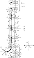
Figure 1 is a partial and schematic plan view of a capping machine according to the invention; -
Figure 2 is a front view of portion of the capping machine ofFigure 1 , with parts removed for clarity; -
Figure 3 shows, in a perspective view and in enlarged scale, a gripping device of the capping machine ofFigure 1 during a capping operation on a respective product container; -
Figure 4 shows opposite front views of the gripping device ofFigure 4 taken from a point of observation placed on the product container during the capping operation; and -
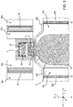
Figure 5 is a side view, with parts removed for clarity and in an enlarged scale, of the gripping device ofFigures 3 and4 during the capping operation on the product container. - With reference to
Figure 1 , numeral 1 indicates, as a whole, a capping machine, in particular for applying internally threadedround caps 2 on product containers,e.g. bottles 3 containing for example pourable liquid products. -
Bottles 3 are fed to the capping machine already filled with a predetermined quantity of product, and may be made for instance of a plastic material or glass. Preferably,bottles 3 are filled with a food product such as milk, fruit juice, wine, coke, etc. Alternatively,bottles 3 may be filled with industrial or cosmetic products like lubricant oil, liquid soap, detergents, etc. - In the shown embodiment, each
bottle 3 is defined by an elongated cylindrical-like body (Figure 2 ,3 and5 ) that has alateral wall 4 and extends parallel to a vertical direction Y from abase 5 to aneck 6, which is opposite to thebase 5; in particular, thelateral wall 4 has an upper portion tapering to theneck 6, which has a diameter lower than that of thebase 5. - Here and in the following, terms such as "lower", "upper", "lateral", "side", "downwards", "upwards", "below", "above", etc...., have to be referred to the normal use conditions of a capping machine.
- Each
neck 6 has a lowercylindrical portion 6a (Figure 5 ) joined to thelateral wall 4 and an uppercylindrical portion 6b having the same diameter as the one ofportion 6a and being externally threaded. - Each
cap 2 is suitable for being screwed onto one corresponding threadedportion 6b according to a direction parallel to direction Y. In particular, eachcap 2 is defined by a disk-shaped end wall 2a and a by cylindricallateral wall 2b protruding orthogonally from the outer profile of theend wall 2a and on one side only thereof. Thelateral wall 2b is internally threaded and is axially delimited between theend wall 2a to a freecircular edge 2c. - As visible in
Figure 1 , capping machine 1 comprises: - a
conveyor apparatus 8 configured to advance thebottles 3 in one row according to a moving direction (indicated by arrows inFigures 1 and4 ) along a path Q; and - a
cap screwing unit 9 configured to screw thecaps 2 onto theportions 6b of the respective bottles 3while thebottles 3 themselves are traveling along a capping stretch Q2 of the path Q. - Preferably, the path Q extends parallel to a horizontal direction X and, therefore, is rectilinear.
- The
conveyor apparatus 8 comprises afirst conveyor member 11 that extends along a feeding stretch Q1 of the path Q, arranged upstream of the capping stretch Q2 with reference to the moving direction of thebottles 3. - In particular, the
first conveyor member 11 comprises a lower conveyor belt 12 (Figure 2 ) supporting thebases 5 of thebottles 3 to drive the latter along the stretch Q1, and a pair of upperpassive belts 13 arranged at respective lateral sides ofconveyor belt 12 and cooperating in contact withlateral walls 4 ofbottles 3, so as to prevent lateral displacements of thebottles 3 themselves. - Moreover,
passive belts 13 prevent also rotations of thebottles 3 around their respective axes A, so thatbottles 3 are fed toconveyor belt 12 with a controlled and predetermined orientation that does not change during the travel of thebottles 3 along the stretch Q1. - Furthermore, the
conveyor apparatus 8 comprises asecond conveyor member 14 extending along the stretch Q2 and preferably comprising a couple ofendless tracks portions passive belts 13. - The
second conveyor member 14 further comprises a plurality of bottle handling devices 18 (Figure 3 ), each of which is adapted to clamp and holdportion 6a ofneck 6 of onebottle 3 by means of twojaws carts - In particular, the
carts corresponding device 18 are self-movable and move alongtracks track Figure 5 ) formed by a plurality of individually excitable solenoids, whilstcarts tracks - Immediately before the beginning of the
branches bottles 3, thetracks carts respective jaws bottles 3 are supplied by thefirst conveyor member 11 torespective devices 18 at the end of the stretch Q1 (i.e. at the beginning of the stretch Q2), wherejaws portion 6a ofneck 6 of onerespective bottle 3. - Then, the
bottles 3 are driven at the velocity V2 through thejaws jaws bottle 3 maintains its own orientation during the clamping and the transport phase along the stretch Q2. - As shown in
Figure 1 , theconveyor apparatus 8 also comprises athird conveyor member 20 extending along a delivery stretch Q3 of the path Q, downstream of the stretch Q2 with reference to the moving direction of thebottles 3. - At the end of the stretch Q2 (i.e. at the beginning of the stretch Q3), the
tracks jaws bottles 3 onto aconveyor belt 21 of thethird conveyor member 20. - The
third conveyor member 20 receivesbottles 3 that are already closed bycaps 2. Moreover, theconveyor member 20 is constructively similar to theconveyor member 11, so it is not described in further detail. - With reference to the enclosed Figures,
cap screwing unit 9 comprises a plurality ofgripping devices 25 configured to screwrespective caps 2 onto thebottles 3. Eachgripping device 25 receives acorresponding cap 2 at a station I and moves parallel to direction X along a path P. Path P extends downstream of the station I and is aligned above the capping stretch Q2 of path Q. -
Cap screwing unit 9 further comprises an infeed assembly 26 (Figures 1 and2 ) for feeding thecaps 2 to thegripping devices 25 at the station I. - More specifically, the
incoming cap 2 at the station I has its axis parallel to direction Y. In particular, theend wall 2a of eachcap 2 is horizontally oriented and thelateral wall 2b extends downward from theend wall 2a. - The infeed
assembly 26 comprises, in particular, a conveyor, preferably defined by a chute 28 (Figure 2 ), for advancingcaps 2 toward station I. Moreover, the infeedassembly 26 further comprises astop device 33 for stopping thecaps 2 downstream of thechute 28. In particular, thecaps 2 rest onto thechute 28 with theedges 2c in contact with thechute 28. - Furthermore, the infeed
assembly 26 comprises two facinglateral belts 34, frictionally interacting withlateral walls 2b ofcaps 2 and independently drivable with different velocities. - Therefore, the
belts 34 guide thecaps 2 toward the station I. In addition, thebelts 34 contextually impose a predetermined orientation tocaps 2 while feeding the latter to thegripping devices 25. - With reference to
Figure 1 ,cap screwing unit 9 further comprises twoendless tracks portions branches branches gripping devices 25 therebetween. - According to the shown embodiment, the
endless tracks - As a possible alternative not shown, paths R1, R2 may be also arranged on parallel vertical planes placed on both sides of path P.
- According to an aspect of the present invention,
cap screwing unit 9 comprises a fist and a second plurality ofcarts tracks carts 25a are relatively movable with respect tocarts 25b. - One
cart 25a and onecart 25b make part of one corresponding grippingdevice 25 when bothcarts respective branches carts gripping device 25 have at least respective portions that are facing each other along the direction Z. Preferably, twocarts device 25. - Advantageously, all
carts 25a and allcarts 25b are self-movable and respectively move along the correspondingtracks - More specifically,
carts tracks carts tracks Figure 5 ,tracks respective armatures 22, whilstcarts - In the shown embodiment, when a
gripping device 25 is formed (Figure 3 ), the correspondingcarts seat 40 having a dimension along direction Z such that thesame housing 40 is suitable to be engaged by acap 2 in a sliding manner along direction X. - In particular,
carts respective recesses housing 40 and preferably have the same depth along direction Z. More specifically, bothrecesses vertical surfaces Figures 3 ,4 ). -
Vertical surfaces lateral wall 2b of acap 2 when the respectivegripping device 25 receivessuch cap 2. - For instance, surfaces 41a, 41b are textured, conveniently with the same texture of the
lateral wall 2b of therespective cap 2, in order to increase friction betweensurfaces lateral wall 2b itself. In this way, surfaces 41a, 41b allow a controlled sliding of thecap 2 engaged therebetween. Furthermore, recesses 40a, 40b are upwardly delimited by respectivecontoured surfaces end wall 2a of acap 2 when thegripping device 25 receivessuch cap 2. - The received
cap 2 engages both therecesses same cap 2 already had at the station I. -
Contoured surfaces cap 2 along direction Y. In particular, thecontoured surfaces surfaces contoured surfaces respective surfaces - Advantageously, the above cam profiles have respective opposite vertical developments with respect to the horizontal moving direction of the
bottles 3, i.e. to the direction X. In other words, the cam profiles are mirror-symmetrical to each other with respect to an ideal plane extending along the moving direction of thebottles 3 orcaps 2, i.e. stretch Q2 or path P. - In the specific embodiment shown in the enclosed Figures, contoured
surfaces 42a are defined by declining ramps in the moving direction of thecarts 25a along path P; in a different manner, contouredsurfaces 42b are defined by climbing ramps in the moving direction of thecarts 25b along path P. - As illustrated in
Figure 3 , to guarantee a horizontal orientation of theend wall 2a when one grippingdevice 25 receives onecap 2, the mutual position of thecarts contoured surfaces end wall 2a are at the same height level. - Therefore, once a
cap 2 has been received by agripping device 25, that grippingdevice 25 can be operated along the path P for giving a screw motion to thecap 2. - According to a further aspect of the invention, the screw motion is obtained by moving the
carts cap 2 is obtained by controlling/changing the speed of thecarts cap 2 has a screw motion parallel to direction Y once thecarts - In other words, the variation in the mutual position along direction X between the
carts cap 2, which, as a result of the engagement between the internal thread oflateral wall 2b of thecap 2 itself and the threadedportion 6b of theneck 6 of therespective bottle 3, results in a helical movement ofsuch cap 2 along an axis parallel to direction Y. - According to the shown embodiment, the relative motion between
carts surfaces lateral wall 2a of thecap 2 held by the respectivegripping device 25. - Therefore, the
cap 2 receives a torque causing the rolling of thecap 2 onto bothsurfaces cap 2 translates relatively to thesurfaces contoured surfaces cap 2 along direction Y. - According to a preferred aspect of the invention,
cap screwing unit 9 further comprises a sensor system SS having a plurality of transducers configured to: - detect a corresponding plurality of quantities indicative of the positions of each of the
bottles 3,carts - generate a corresponding plurality of output signals based on the respective detected quantities.
- Preferably, the transducers may be partly selected from the group of optical position sensors, like for instance linear or angular encoders (in particular coupled to
conveyor members 11, 20), infrared or visible-field cameras, laser sensors, etc., or from the groups of inductive/capacitive sensors. - Moreover,
cap screwing unit 9 also comprises an electronic control unit ECU that is connected to the sensor system SS such as to receive signals generated therewith and is configured to extract from such signals information relative to the positions ofbottles 3,carts - The electronic control unit ECU is further configured to coordinate on the basis of the above information the relative movement of
carts tracks - During the operation of the capping machine 1, a row of
bottles 3 is transported by theconveyor member 11 along the stretch Q1. - Simultaneously, the electronic control unit ECU moves
carts respective tracks carts - The electronic control unit ECU synchronizes:
- the arriving of a
bottle 3 exactly below the station I; and - a relative positioning of one
cart 25a and onecart 25b at a receiving configuration RC, in which the latter form the relativegripping device 25. - In the receiving configuration RC,
carts cap 2 at the station I before starting to travel on therespective branches Such cap 2 is axially aligned above the threadedportion 6b of theneck 6 of thebottle 3 arrived below the station I. - In particular, at the receiving configuration RC, the
cart 25a meets thecap 2 at arearward end portion 45a thereof, in respect to the moving direction ofbottles 3. On the other hand, thecart 25b meets thecap 2 at theforward end portion 45b thereof. - Therefore, the
cart 25a is placed ahead than thecart 25b at the receiving configuration RC. - When the
bottle 3 arrives at the beginning of the stretch Q2, the electronic control unit ECU positions thejaws carts - Hence, the
jaws portion 6a of theneck 6 such that therespective bottle 3 can move forward in reply to the joint movement of thecarts carts cap 2 remains aligned above the corresponding threadedportion 6b of theneck 6 of thebottle 3. - Then, the electronic control unit ECU drives
carts cap 2, thebottle 3 and bothcarts carts - Here, the electronic control unit ECU starts to drive the
carts - Velocity V1 is higher than velocity V3.
- For instance, the difference between the velocities V1, V3 may be equal to the velocity V2. Thus, considering ideal gripping conditions, the
cap 2 would roll onto bothsurfaces - a translational velocity along the X axis equal to V2; and
- an angular velocity around the Y axis that is the product of the velocity V2 and the radius of the
cap 2. - Therefore, the
cap 2 always remains axially aligned above the threadedportion 6b of therespective bottle 3 while thesame cap 2 has a screw motion toward the threadedportion 6b itself. As already disclosed above, the vertical component of such screw motion is guided by thecontoured surfaces - The
cap 2 is then screwed onto the threadedportion 6b of theneck 6 of therespective bottle 3. Based on the extensions of thesurfaces cap 2 can perform more than one round about the axis A. - At the final configuration FC, the
cap 2 is respectively placed at aforward end portion 46a of thecart 25a and at a rearward end portion of thecart 25b, according to the moving direction of thebottles 3. In particular, the mutual position of thecarts same carts - More specifically, between the starting and the final configurations SC, FC, the
carts surfaces cap 2 is placed at respectivecentral portions relative carts - After the final configuration FC is reached, the electronic control unit ECU starts to drive again the
carts cap 2 stops to roll onto thesurfaces - Finally, the
carts branches cap 2, whilejaws bottle 3 onto theconveyor belt 21. - From the above, the advantages of the invention become apparent to a person skilled in the specific sector of capping machines for capping product containers.
- In particular,
carts gripping device 25 can independently move with respect to one another. Accordingly, eachcart respective track - Therefore, the capping machine 1 is suitable for screwing caps with different shapes onto
respective bottles 3, without any need of a re-configuration ofgripping devices 25. - Moreover, there is no need of actively controlling the movement of the
bottles 3 along the stretch Q1 with the movement ofcarts - Indeed, the electronic control unit ECU drives the
carts gripping devices 25 along the path P are synchronized with thebottles 3 along the stretch Q2. - Since the
carts respective surfaces caps 2, the electronic control unit ECU can control the movement ofcarts cap 2. - Therefore, the
gripping devices 25 allow the fast screwing of thecaps 2 with very high accuracy. The texturing of thesurfaces gripping device 25 and so the efficiency of the whole capping machine 1. - In view of the above, it becomes apparent to a skilled person in the field that modifications and changes may be applied to the capping machine 1 as above described without exiting from the scope of protection as defined in the appended claims.
- In particular, the path P and the stretch Q2 may also not be rectilinear; and/or the
gripping device 25 may not be simply defined by onecart 25a and onecart 25b. - For example, the gripping
device 25 may comprise many kinds of known transmissions that transform an input relative motion betweencarts cap 2. - Furthermore,
carts carts stator armature 40 may be carried by thecarts tracks - The
conveyor apparatus 8 may have many different arrangements with respect to that illustrated. In particular, theconveyor apparatus 8 may consist of a single linear conveyor belt below thebottles 3 and/or one or more star wheels. - Eventually,
cap screwing unit 9 can be adopted for screwing internally threaded caps onto other kinds of containers thanbottles 3, e.g. jars containing solid or semi-solid products, possibly immersed in a liquid, such as marmalade, tuna, pickles, olives, etc.
Claims (13)
- A capping machine (9) comprising:- a conveyor apparatus (8) advancing, in use, a plurality of product containers (3) along a first path (Q);- at least one gripping device (25) movable along a second path (P) and configured to receive and hold at least one internally threaded cap (2) suitable for being screwed onto an externally threaded neck (6) of one respective container (3); said second path (P) comprising at least a screwing stretch, which is placed above, and aligned with, at least a conveyor stretch (Q2) of said first path (Q) and in which one said cap (2) is screwed, in use, onto said neck (6) of one respective container (3);characterized in that said gripping device (25) comprises a first and a second cart (25a, 25b) that are configured to retain therebetween the cap (2) to be screwed on the respective container (3) and that are movable along respective track portions (39a, 39b) extending parallel to said second path (P); and in that said first cart (25a) is movable relatively to said second cart (25b) at least when said gripping device (25) moves along said screwing stretch so as to impart a rotary motion to said cap (2) resulting in use in a screw motion on the neck (6) of the respective container (3).
- The capping machine according to claim 1, wherein said first and second carts (25a, 25b) are self-movable.
- The capping machine according to claim 2, further comprising:- a sensor system (SS) configured to generate one or more signals associated to respective quantities that are indicative of the position of said containers (3);- an electronic control unit (ECU) that is coupled to said sensor system (SS) to receive said signals and extract from said signals information relative to the position of said containers (3), the electronic control unit (ECU) being configured to control the movement of said first and second carts (25a, 25b) on the basis of said information.
- The capping machine according to any one of the preceding claims, wherein said screwing stretch is rectilinear.
- The capping machine according to any one of the preceding claims, wherein said track portions (39a, 39b) are part of respective endless tracks (38a, 38b) arranged on respective opposite lateral sides of said screwing stretch of said second path (P).
- The capping machine according to any one of the preceding claims, wherein said track portions (39a, 39b) are spaced from one another, said screwing stretch being intermediately placed between said track portions (39a, 39b) and laying with said track portions (39a, 39b) on a motion plane for said gripping device (25).
- The capping machine according to claim 6, wherein said first and second carts (25a, 25b) have respective recesses (40a, 40b) forming a seat (40) suitable for being engaged by said cap (2), said recesses (40a, 40b) being respectively delimited by:- a first and a second textured surface (41a, 41b) parallel to one another when said gripping device (25) moves along said screwing stretch and allowing a controlled sliding of the engaged cap (2); and- a first and a second cam surface (42a, 42b) respectively intersecting said first and second textured surfaces (41a, 41b) such to form respective cam profiles, which are mirror-symmetrical with respect to said motion plane;wherein said first and second cam surface (42a, 42b) are ramp-shaped to guide, in use, the translational component of said screw motion of the respective cap (2) and extend transversally to said textured surfaces (41a, 41b) .
- The capping machine according to any one of the preceding claims, wherein said conveyor apparatus (8) comprises a conveyor member (12) having third and fourth carts (19a, 19b) and respective conveyor tracks (16a, 16b) to which said third and fourth carts (19a, 19b) are respectively coupled in a sliding manner;
said third and fourth carts (19a, 19b) being self-movable along respective conveyor track portions (17a, 17b) of said conveyor tracks (16a, 16b) extending parallel to said conveyor stretch (Q2). - The capping machine according to claim 8, wherein each of said third carts (19a) and each of said fourth carts (19b) comprise respectively a first and a second jaw (18a, 18b) configured to clamp one of said containers (3).
- A method for operating a capping machine according to any one of the preceding claims, the method comprising the steps of:- moving said gripping device (25) along said second path (P);- feeding one cap (2) to said gripping device (25);- holding said cap (2) through said gripping device (25) so as to maintain an axis of said cap (2) aligned with, and above, an axis of one respective container (2), at least when said gripping device (25) moves along said screwing stretch; and- engaging said cap (2) with the neck (6) of said container (3);characterized by further comprising the step of:- imparting a rotary motion to said cap (2) by moving said first cart (25a) relatively to said second cart (25b), so as to produce a screw motion onto said neck (6) of said container (3).
- The method according to claim 10, wherein said gripping device (25) is initially moved along said stretch according to a first velocity (V2), and in that said rotary motion is imparted to said cap (2) by changing the respective velocities of said first and second cart (25a, 25b), so that said first and second cart (25a, 25b) move respectively according to a second and a third velocity (V1, V3); said second velocity (V1) being greater than said third velocity (V3).
- The method according to claim 10 or 11, wherein said gripping device (25) is moved along said second path (P) passing from a first configuration (RC), in which said gripping device receives and holds one respective cap (2) in a housing (40) between said first and second cart (25a, 25b), to a second configuration in which said gripping device (25) releases said cap (2) screwed onto the respective container (3);
the first cart (25a) being behind and respectively ahead the second cart (25b) along said screwing stretch, when said gripping device (25) is in the first and in the second configuration. - The method according to claim 12, wherein said gripping device (25) is moved so as to reach a third configuration (IC) between said first and second configurations;
said first and second carts (25a, 25b) having at the third configuration (IC) respective parallel surfaces (41a, 41b) that are faced to each other and are both in contact with the respective said cap (2) at respective central portions of said surfaces (41a, 41b).
Priority Applications (2)
| Application Number | Priority Date | Filing Date | Title |
|---|---|---|---|
| EP18306084.7A EP3608287B1 (en) | 2018-08-07 | 2018-08-07 | Capping machine and operating method thereof |
| PCT/EP2019/069647 WO2020030416A1 (en) | 2018-08-07 | 2019-07-22 | Capping machine and operating method thereof |
Applications Claiming Priority (1)
| Application Number | Priority Date | Filing Date | Title |
|---|---|---|---|
| EP18306084.7A EP3608287B1 (en) | 2018-08-07 | 2018-08-07 | Capping machine and operating method thereof |
Publications (2)
| Publication Number | Publication Date |
|---|---|
| EP3608287A1 true EP3608287A1 (en) | 2020-02-12 |
| EP3608287B1 EP3608287B1 (en) | 2021-03-31 |
Family
ID=63209370
Family Applications (1)
| Application Number | Title | Priority Date | Filing Date |
|---|---|---|---|
| EP18306084.7A Active EP3608287B1 (en) | 2018-08-07 | 2018-08-07 | Capping machine and operating method thereof |
Country Status (2)
| Country | Link |
|---|---|
| EP (1) | EP3608287B1 (en) |
| WO (1) | WO2020030416A1 (en) |
Families Citing this family (3)
| Publication number | Priority date | Publication date | Assignee | Title |
|---|---|---|---|---|
| CN111960356A (en) * | 2020-09-10 | 2020-11-20 | 砀山县虹桥食品有限公司 | Quick packaging hardware of canned fruit |
| JP7455306B2 (en) * | 2021-02-12 | 2024-03-26 | 株式会社サイレック | capper |
| JP2023153717A (en) * | 2022-04-05 | 2023-10-18 | 株式会社サイレック | capper |
Citations (3)
| Publication number | Priority date | Publication date | Assignee | Title |
|---|---|---|---|---|
| US20070193226A1 (en) * | 2006-02-21 | 2007-08-23 | Luc Jalbert | Apparatus and method for rotating a cap relatively to a container |
| EP2746175A1 (en) * | 2012-12-21 | 2014-06-25 | Tetra Laval Holdings & Finance S.A. | Unit for the application of opening devices on sealed packages of food products |
| US20150166317A1 (en) * | 2013-12-16 | 2015-06-18 | Eli Uriel | Hybrid capper |
-
2018
- 2018-08-07 EP EP18306084.7A patent/EP3608287B1/en active Active
-
2019
- 2019-07-22 WO PCT/EP2019/069647 patent/WO2020030416A1/en not_active Ceased
Patent Citations (3)
| Publication number | Priority date | Publication date | Assignee | Title |
|---|---|---|---|---|
| US20070193226A1 (en) * | 2006-02-21 | 2007-08-23 | Luc Jalbert | Apparatus and method for rotating a cap relatively to a container |
| EP2746175A1 (en) * | 2012-12-21 | 2014-06-25 | Tetra Laval Holdings & Finance S.A. | Unit for the application of opening devices on sealed packages of food products |
| US20150166317A1 (en) * | 2013-12-16 | 2015-06-18 | Eli Uriel | Hybrid capper |
Also Published As
| Publication number | Publication date |
|---|---|
| WO2020030416A1 (en) | 2020-02-13 |
| EP3608287B1 (en) | 2021-03-31 |
Similar Documents
| Publication | Publication Date | Title |
|---|---|---|
| JP4885137B2 (en) | Device for grouping individual goods | |
| US9682829B2 (en) | Method and transport device for converting a first container stream into a second container stream | |
| US9085420B2 (en) | Orienting apparatus and method | |
| US9283709B2 (en) | Container treatment plant comprising an oven and a blow molder with individually driven carriers for preforms | |
| EP3608287B1 (en) | Capping machine and operating method thereof | |
| US7481309B2 (en) | Method of separating, synchronizing and compacting packed groups of articles | |
| EP2746165A1 (en) | Device for gripping and transferring individual products | |
| US8404175B2 (en) | Method and device for the production of plastic packaging containers | |
| EP3254994A1 (en) | A conveying wheel for transporting articles and an apparatus for handling articles including at least one such conveying wheel | |
| US10640300B2 (en) | System and method for aligning an object | |
| ZA896763B (en) | Article separating and loading apparatus | |
| EP4003845B1 (en) | An article picking and treating apparatus | |
| KR20150096790A (en) | Unit for the application of opening devices on sealed packages of food products | |
| US8939272B2 (en) | Article orienting machine | |
| ES2982363T3 (en) | Packaging device | |
| CN101336159B (en) | Unit for applying opening devices to packages of pourable food products | |
| EP1578680B1 (en) | Method and apparatus for arranging and orienting packages | |
| US9434548B2 (en) | Installation for processing articles, the installation including a screw transfer device | |
| US20150166317A1 (en) | Hybrid capper | |
| CN220616437U (en) | Apparatus for manufacturing packaged products | |
| CN101717000B (en) | Anti-fleeing package process and system of filled and sealed bottled liquid state products | |
| KR200464716Y1 (en) | Case moving apparatus | |
| CN107000879A (en) | For the former for the base portion for forming container | |
| CN214059055U (en) | Single-channel linear bottle arranging device | |
| CN121419931A (en) | Grouping equipment, methods, and facilities for lateral transfer of products |
Legal Events
| Date | Code | Title | Description |
|---|---|---|---|
| PUAI | Public reference made under article 153(3) epc to a published international application that has entered the european phase |
Free format text: ORIGINAL CODE: 0009012 |
|
| STAA | Information on the status of an ep patent application or granted ep patent |
Free format text: STATUS: THE APPLICATION HAS BEEN PUBLISHED |
|
| AK | Designated contracting states |
Kind code of ref document: A1 Designated state(s): AL AT BE BG CH CY CZ DE DK EE ES FI FR GB GR HR HU IE IS IT LI LT LU LV MC MK MT NL NO PL PT RO RS SE SI SK SM TR |
|
| AX | Request for extension of the european patent |
Extension state: BA ME |
|
| STAA | Information on the status of an ep patent application or granted ep patent |
Free format text: STATUS: REQUEST FOR EXAMINATION WAS MADE |
|
| 17P | Request for examination filed |
Effective date: 20200605 |
|
| RBV | Designated contracting states (corrected) |
Designated state(s): AL AT BE BG CH CY CZ DE DK EE ES FI FR GB GR HR HU IE IS IT LI LT LU LV MC MK MT NL NO PL PT RO RS SE SI SK SM TR |
|
| GRAP | Despatch of communication of intention to grant a patent |
Free format text: ORIGINAL CODE: EPIDOSNIGR1 |
|
| STAA | Information on the status of an ep patent application or granted ep patent |
Free format text: STATUS: GRANT OF PATENT IS INTENDED |
|
| INTG | Intention to grant announced |
Effective date: 20210118 |
|
| GRAS | Grant fee paid |
Free format text: ORIGINAL CODE: EPIDOSNIGR3 |
|
| GRAA | (expected) grant |
Free format text: ORIGINAL CODE: 0009210 |
|
| STAA | Information on the status of an ep patent application or granted ep patent |
Free format text: STATUS: THE PATENT HAS BEEN GRANTED |
|
| AK | Designated contracting states |
Kind code of ref document: B1 Designated state(s): AL AT BE BG CH CY CZ DE DK EE ES FI FR GB GR HR HU IE IS IT LI LT LU LV MC MK MT NL NO PL PT RO RS SE SI SK SM TR |
|
| REG | Reference to a national code |
Ref country code: GB Ref legal event code: FG4D Ref country code: CH Ref legal event code: EP |
|
| REG | Reference to a national code |
Ref country code: AT Ref legal event code: REF Ref document number: 1376739 Country of ref document: AT Kind code of ref document: T Effective date: 20210415 |
|
| REG | Reference to a national code |
Ref country code: DE Ref legal event code: R096 Ref document number: 602018014690 Country of ref document: DE |
|
| REG | Reference to a national code |
Ref country code: IE Ref legal event code: FG4D |
|
| REG | Reference to a national code |
Ref country code: LT Ref legal event code: MG9D |
|
| PG25 | Lapsed in a contracting state [announced via postgrant information from national office to epo] |
Ref country code: BG Free format text: LAPSE BECAUSE OF FAILURE TO SUBMIT A TRANSLATION OF THE DESCRIPTION OR TO PAY THE FEE WITHIN THE PRESCRIBED TIME-LIMIT Effective date: 20210630 Ref country code: FI Free format text: LAPSE BECAUSE OF FAILURE TO SUBMIT A TRANSLATION OF THE DESCRIPTION OR TO PAY THE FEE WITHIN THE PRESCRIBED TIME-LIMIT Effective date: 20210331 Ref country code: HR Free format text: LAPSE BECAUSE OF FAILURE TO SUBMIT A TRANSLATION OF THE DESCRIPTION OR TO PAY THE FEE WITHIN THE PRESCRIBED TIME-LIMIT Effective date: 20210331 Ref country code: NO Free format text: LAPSE BECAUSE OF FAILURE TO SUBMIT A TRANSLATION OF THE DESCRIPTION OR TO PAY THE FEE WITHIN THE PRESCRIBED TIME-LIMIT Effective date: 20210630 |
|
| PG25 | Lapsed in a contracting state [announced via postgrant information from national office to epo] |
Ref country code: RS Free format text: LAPSE BECAUSE OF FAILURE TO SUBMIT A TRANSLATION OF THE DESCRIPTION OR TO PAY THE FEE WITHIN THE PRESCRIBED TIME-LIMIT Effective date: 20210331 Ref country code: LV Free format text: LAPSE BECAUSE OF FAILURE TO SUBMIT A TRANSLATION OF THE DESCRIPTION OR TO PAY THE FEE WITHIN THE PRESCRIBED TIME-LIMIT Effective date: 20210331 Ref country code: SE Free format text: LAPSE BECAUSE OF FAILURE TO SUBMIT A TRANSLATION OF THE DESCRIPTION OR TO PAY THE FEE WITHIN THE PRESCRIBED TIME-LIMIT Effective date: 20210331 |
|
| REG | Reference to a national code |
Ref country code: NL Ref legal event code: MP Effective date: 20210331 |
|
| REG | Reference to a national code |
Ref country code: AT Ref legal event code: MK05 Ref document number: 1376739 Country of ref document: AT Kind code of ref document: T Effective date: 20210331 |
|
| PG25 | Lapsed in a contracting state [announced via postgrant information from national office to epo] |
Ref country code: EE Free format text: LAPSE BECAUSE OF FAILURE TO SUBMIT A TRANSLATION OF THE DESCRIPTION OR TO PAY THE FEE WITHIN THE PRESCRIBED TIME-LIMIT Effective date: 20210331 Ref country code: CZ Free format text: LAPSE BECAUSE OF FAILURE TO SUBMIT A TRANSLATION OF THE DESCRIPTION OR TO PAY THE FEE WITHIN THE PRESCRIBED TIME-LIMIT Effective date: 20210331 Ref country code: LT Free format text: LAPSE BECAUSE OF FAILURE TO SUBMIT A TRANSLATION OF THE DESCRIPTION OR TO PAY THE FEE WITHIN THE PRESCRIBED TIME-LIMIT Effective date: 20210331 Ref country code: SM Free format text: LAPSE BECAUSE OF FAILURE TO SUBMIT A TRANSLATION OF THE DESCRIPTION OR TO PAY THE FEE WITHIN THE PRESCRIBED TIME-LIMIT Effective date: 20210331 Ref country code: NL Free format text: LAPSE BECAUSE OF FAILURE TO SUBMIT A TRANSLATION OF THE DESCRIPTION OR TO PAY THE FEE WITHIN THE PRESCRIBED TIME-LIMIT Effective date: 20210331 Ref country code: AT Free format text: LAPSE BECAUSE OF FAILURE TO SUBMIT A TRANSLATION OF THE DESCRIPTION OR TO PAY THE FEE WITHIN THE PRESCRIBED TIME-LIMIT Effective date: 20210331 |
|
| PG25 | Lapsed in a contracting state [announced via postgrant information from national office to epo] |
Ref country code: PT Free format text: LAPSE BECAUSE OF FAILURE TO SUBMIT A TRANSLATION OF THE DESCRIPTION OR TO PAY THE FEE WITHIN THE PRESCRIBED TIME-LIMIT Effective date: 20210802 Ref country code: PL Free format text: LAPSE BECAUSE OF FAILURE TO SUBMIT A TRANSLATION OF THE DESCRIPTION OR TO PAY THE FEE WITHIN THE PRESCRIBED TIME-LIMIT Effective date: 20210331 Ref country code: RO Free format text: LAPSE BECAUSE OF FAILURE TO SUBMIT A TRANSLATION OF THE DESCRIPTION OR TO PAY THE FEE WITHIN THE PRESCRIBED TIME-LIMIT Effective date: 20210331 Ref country code: SK Free format text: LAPSE BECAUSE OF FAILURE TO SUBMIT A TRANSLATION OF THE DESCRIPTION OR TO PAY THE FEE WITHIN THE PRESCRIBED TIME-LIMIT Effective date: 20210331 Ref country code: IS Free format text: LAPSE BECAUSE OF FAILURE TO SUBMIT A TRANSLATION OF THE DESCRIPTION OR TO PAY THE FEE WITHIN THE PRESCRIBED TIME-LIMIT Effective date: 20210731 |
|
| REG | Reference to a national code |
Ref country code: DE Ref legal event code: R097 Ref document number: 602018014690 Country of ref document: DE |
|
| PG25 | Lapsed in a contracting state [announced via postgrant information from national office to epo] |
Ref country code: ES Free format text: LAPSE BECAUSE OF FAILURE TO SUBMIT A TRANSLATION OF THE DESCRIPTION OR TO PAY THE FEE WITHIN THE PRESCRIBED TIME-LIMIT Effective date: 20210331 Ref country code: DK Free format text: LAPSE BECAUSE OF FAILURE TO SUBMIT A TRANSLATION OF THE DESCRIPTION OR TO PAY THE FEE WITHIN THE PRESCRIBED TIME-LIMIT Effective date: 20210331 Ref country code: AL Free format text: LAPSE BECAUSE OF FAILURE TO SUBMIT A TRANSLATION OF THE DESCRIPTION OR TO PAY THE FEE WITHIN THE PRESCRIBED TIME-LIMIT Effective date: 20210331 |
|
| PLBE | No opposition filed within time limit |
Free format text: ORIGINAL CODE: 0009261 |
|
| STAA | Information on the status of an ep patent application or granted ep patent |
Free format text: STATUS: NO OPPOSITION FILED WITHIN TIME LIMIT |
|
| 26N | No opposition filed |
Effective date: 20220104 |
|
| REG | Reference to a national code |
Ref country code: CH Ref legal event code: PL |
|
| PG25 | Lapsed in a contracting state [announced via postgrant information from national office to epo] |
Ref country code: MC Free format text: LAPSE BECAUSE OF FAILURE TO SUBMIT A TRANSLATION OF THE DESCRIPTION OR TO PAY THE FEE WITHIN THE PRESCRIBED TIME-LIMIT Effective date: 20210331 |
|
| REG | Reference to a national code |
Ref country code: BE Ref legal event code: MM Effective date: 20210831 |
|
| PG25 | Lapsed in a contracting state [announced via postgrant information from national office to epo] |
Ref country code: LI Free format text: LAPSE BECAUSE OF NON-PAYMENT OF DUE FEES Effective date: 20210831 Ref country code: CH Free format text: LAPSE BECAUSE OF NON-PAYMENT OF DUE FEES Effective date: 20210831 |
|
| PG25 | Lapsed in a contracting state [announced via postgrant information from national office to epo] |
Ref country code: IS Free format text: LAPSE BECAUSE OF FAILURE TO SUBMIT A TRANSLATION OF THE DESCRIPTION OR TO PAY THE FEE WITHIN THE PRESCRIBED TIME-LIMIT Effective date: 20210731 Ref country code: LU Free format text: LAPSE BECAUSE OF NON-PAYMENT OF DUE FEES Effective date: 20210807 |
|
| PG25 | Lapsed in a contracting state [announced via postgrant information from national office to epo] |
Ref country code: IE Free format text: LAPSE BECAUSE OF NON-PAYMENT OF DUE FEES Effective date: 20210807 Ref country code: BE Free format text: LAPSE BECAUSE OF NON-PAYMENT OF DUE FEES Effective date: 20210831 |
|
| PGFP | Annual fee paid to national office [announced via postgrant information from national office to epo] |
Ref country code: IT Payment date: 20220720 Year of fee payment: 5 Ref country code: DE Payment date: 20220720 Year of fee payment: 5 |
|
| PGFP | Annual fee paid to national office [announced via postgrant information from national office to epo] |
Ref country code: FR Payment date: 20220721 Year of fee payment: 5 |
|
| GBPC | Gb: european patent ceased through non-payment of renewal fee |
Effective date: 20220807 |
|
| PG25 | Lapsed in a contracting state [announced via postgrant information from national office to epo] |
Ref country code: CY Free format text: LAPSE BECAUSE OF FAILURE TO SUBMIT A TRANSLATION OF THE DESCRIPTION OR TO PAY THE FEE WITHIN THE PRESCRIBED TIME-LIMIT Effective date: 20210331 |
|
| PG25 | Lapsed in a contracting state [announced via postgrant information from national office to epo] |
Ref country code: HU Free format text: LAPSE BECAUSE OF FAILURE TO SUBMIT A TRANSLATION OF THE DESCRIPTION OR TO PAY THE FEE WITHIN THE PRESCRIBED TIME-LIMIT; INVALID AB INITIO Effective date: 20180807 Ref country code: GR Free format text: LAPSE BECAUSE OF FAILURE TO SUBMIT A TRANSLATION OF THE DESCRIPTION OR TO PAY THE FEE WITHIN THE PRESCRIBED TIME-LIMIT Effective date: 20210331 |
|
| PG25 | Lapsed in a contracting state [announced via postgrant information from national office to epo] |
Ref country code: GB Free format text: LAPSE BECAUSE OF NON-PAYMENT OF DUE FEES Effective date: 20220807 |
|
| REG | Reference to a national code |
Ref country code: DE Ref legal event code: R119 Ref document number: 602018014690 Country of ref document: DE |
|
| PG25 | Lapsed in a contracting state [announced via postgrant information from national office to epo] |
Ref country code: MK Free format text: LAPSE BECAUSE OF FAILURE TO SUBMIT A TRANSLATION OF THE DESCRIPTION OR TO PAY THE FEE WITHIN THE PRESCRIBED TIME-LIMIT Effective date: 20210331 |
|
| PG25 | Lapsed in a contracting state [announced via postgrant information from national office to epo] |
Ref country code: IT Free format text: LAPSE BECAUSE OF NON-PAYMENT OF DUE FEES Effective date: 20230807 Ref country code: FR Free format text: LAPSE BECAUSE OF NON-PAYMENT OF DUE FEES Effective date: 20230831 Ref country code: DE Free format text: LAPSE BECAUSE OF NON-PAYMENT OF DUE FEES Effective date: 20240301 |
|
| PG25 | Lapsed in a contracting state [announced via postgrant information from national office to epo] |
Ref country code: MT Free format text: LAPSE BECAUSE OF FAILURE TO SUBMIT A TRANSLATION OF THE DESCRIPTION OR TO PAY THE FEE WITHIN THE PRESCRIBED TIME-LIMIT Effective date: 20210331 |
|
| PG25 | Lapsed in a contracting state [announced via postgrant information from national office to epo] |
Ref country code: TR Free format text: LAPSE BECAUSE OF FAILURE TO SUBMIT A TRANSLATION OF THE DESCRIPTION OR TO PAY THE FEE WITHIN THE PRESCRIBED TIME-LIMIT Effective date: 20210331 |