EP3608227A1 - Aircraft interior configuration with flexible use space - Google Patents
Aircraft interior configuration with flexible use space Download PDFInfo
- Publication number
- EP3608227A1 EP3608227A1 EP19189311.4A EP19189311A EP3608227A1 EP 3608227 A1 EP3608227 A1 EP 3608227A1 EP 19189311 A EP19189311 A EP 19189311A EP 3608227 A1 EP3608227 A1 EP 3608227A1
- Authority
- EP
- European Patent Office
- Prior art keywords
- seat
- disposed
- attendant
- seats
- flexible use
- Prior art date
- Legal status (The legal status is an assumption and is not a legal conclusion. Google has not performed a legal analysis and makes no representation as to the accuracy of the status listed.)
- Granted
Links
Images


Classifications
-
- B—PERFORMING OPERATIONS; TRANSPORTING
- B64—AIRCRAFT; AVIATION; COSMONAUTICS
- B64D—EQUIPMENT FOR FITTING IN OR TO AIRCRAFT; FLIGHT SUITS; PARACHUTES; ARRANGEMENT OR MOUNTING OF POWER PLANTS OR PROPULSION TRANSMISSIONS IN AIRCRAFT
- B64D11/00—Passenger or crew accommodation; Flight-deck installations not otherwise provided for
- B64D11/06—Arrangements of seats, or adaptations or details specially adapted for aircraft seats
- B64D11/0639—Arrangements of seats, or adaptations or details specially adapted for aircraft seats with features for adjustment or converting of seats
-
- A—HUMAN NECESSITIES
- A61—MEDICAL OR VETERINARY SCIENCE; HYGIENE
- A61G—TRANSPORT, PERSONAL CONVEYANCES, OR ACCOMMODATION SPECIALLY ADAPTED FOR PATIENTS OR DISABLED PERSONS; OPERATING TABLES OR CHAIRS; CHAIRS FOR DENTISTRY; FUNERAL DEVICES
- A61G3/00—Ambulance aspects of vehicles; Vehicles with special provisions for transporting patients or disabled persons, or their personal conveyances, e.g. for facilitating access of, or for loading, wheelchairs
- A61G3/08—Accommodating or securing wheelchairs or stretchers
- A61G3/0808—Accommodating or securing wheelchairs
-
- B—PERFORMING OPERATIONS; TRANSPORTING
- B64—AIRCRAFT; AVIATION; COSMONAUTICS
- B64D—EQUIPMENT FOR FITTING IN OR TO AIRCRAFT; FLIGHT SUITS; PARACHUTES; ARRANGEMENT OR MOUNTING OF POWER PLANTS OR PROPULSION TRANSMISSIONS IN AIRCRAFT
- B64D11/00—Passenger or crew accommodation; Flight-deck installations not otherwise provided for
- B64D11/06—Arrangements of seats, or adaptations or details specially adapted for aircraft seats
- B64D11/062—Belts or other passenger restraint means for passenger seats
-
- B—PERFORMING OPERATIONS; TRANSPORTING
- B64—AIRCRAFT; AVIATION; COSMONAUTICS
- B64D—EQUIPMENT FOR FITTING IN OR TO AIRCRAFT; FLIGHT SUITS; PARACHUTES; ARRANGEMENT OR MOUNTING OF POWER PLANTS OR PROPULSION TRANSMISSIONS IN AIRCRAFT
- B64D11/00—Passenger or crew accommodation; Flight-deck installations not otherwise provided for
- B64D11/06—Arrangements of seats, or adaptations or details specially adapted for aircraft seats
- B64D11/0627—Seats combined with storage means
-
- B—PERFORMING OPERATIONS; TRANSPORTING
- B64—AIRCRAFT; AVIATION; COSMONAUTICS
- B64D—EQUIPMENT FOR FITTING IN OR TO AIRCRAFT; FLIGHT SUITS; PARACHUTES; ARRANGEMENT OR MOUNTING OF POWER PLANTS OR PROPULSION TRANSMISSIONS IN AIRCRAFT
- B64D11/00—Passenger or crew accommodation; Flight-deck installations not otherwise provided for
- B64D11/06—Arrangements of seats, or adaptations or details specially adapted for aircraft seats
- B64D11/0691—Arrangements of seats, or adaptations or details specially adapted for aircraft seats specially adapted for cabin crew
-
- B—PERFORMING OPERATIONS; TRANSPORTING
- B64—AIRCRAFT; AVIATION; COSMONAUTICS
- B64D—EQUIPMENT FOR FITTING IN OR TO AIRCRAFT; FLIGHT SUITS; PARACHUTES; ARRANGEMENT OR MOUNTING OF POWER PLANTS OR PROPULSION TRANSMISSIONS IN AIRCRAFT
- B64D11/00—Passenger or crew accommodation; Flight-deck installations not otherwise provided for
- B64D11/06—Arrangements of seats, or adaptations or details specially adapted for aircraft seats
- B64D11/0698—Seats suspended from aircraft walls
-
- A—HUMAN NECESSITIES
- A61—MEDICAL OR VETERINARY SCIENCE; HYGIENE
- A61G—TRANSPORT, PERSONAL CONVEYANCES, OR ACCOMMODATION SPECIALLY ADAPTED FOR PATIENTS OR DISABLED PERSONS; OPERATING TABLES OR CHAIRS; CHAIRS FOR DENTISTRY; FUNERAL DEVICES
- A61G2220/00—Adaptations of particular transporting means
- A61G2220/10—Aircrafts
Definitions
- the present disclosure is generally directed to an aircraft interior configuration including flexible use space, and more particularly, flexible use space in the main cabin reconfigurable to accommodate conventional traveling passengers or those requiring securement space for a wheelchair or other items.
- One obstacle is that aircraft aisles are typically too narrow to accommodate a standard width wheelchair.
- Another obstacle involves creating space in the main cabin to accommodate and secure a wheelchair. While the first obstacle can potentially be overcome by creating a certified wheelchair having a narrow width, the second obstacle requires an interior cabin configuration able to accommodate and secure in place a wheelchair without abandoning a traditional passenger seating arrangement, and without sacrificing seating density.
- the present invention is directed to an interior configuration for an aircraft including an aisle extending along a longitudinal direction which in use corresponds to a longitudinal axis of the aircraft, a flexible use space disposed laterally adjacent the aisle, a bulkhead disposed at one end of the flexible use space, and attendant seats disposed in the flexible use space affixed to the bulkhead, with each attendant seat comprising a flip-up seat bottom.
- the flexible use space is reconfigurable between a first configuration in which the attendant seats are used as passenger seats and a second configuration in which at least one seat bottom is flipped up to provide space to receive and secure an item in place on the floor palette.
- the interior configuration may comprise a floor palette disposed in the flexible use space and including at least one seat track and at least one restraint assembly for securing an item in place of the floor palette.
- the invention also relates to an aircraft comprising such an interior.
- the attendant seats may include an inboard attendant seat disposed adjacent the aisle, an outboard attendant seat disposed adjacent a fuselage of the aircraft, and a middle attendant seat disposed between the inboard and outboard attendant seats, wherein in the second configuration the seat bottom of the outboard attendant seat is flipped down for use as a seat and the seat bottom of each of the middle and inboard attendant seats is flipped up to provide securement space in the flexible use space to receive and secure in place a wheelchair on the floor palette.
- the bulkhead may be a rear bulkhead disposed perpendicular to the longitudinal direction, and the attendant seats may be disposed laterally adjacent and forward facing.
- the bulkhead may include at least one seat track for affixing the attendant seats to the bulkhead, and the attendant seats may be free of attachment to the floor palette.
- the floor palette may include at least one seat track disposed perpendicular to the longitudinal axis of the aircraft and at least one seat track disposed parallel to the longitudinal direction.
- the floor palette may, in use, be affixed to the floor of the aircraft and may include at least one recess disposed along an edge thereof positioned in surrounding relation to a leg of a seat disposed adjacent the flexible use space.
- the at least one restraint assembly may include an adjustable length strap having a fastener at each end adapted to engage in the at least one seat track of the floor palette.
- the interior configuration may include passenger seats disposed adjacent the flexible use space, wherein the passenger seats and the attendant seats are disposed in the same facing orientation and are visually similar in appearance.
- Each of the attendant seats may include a frame affixed to the bulkhead and a backrest supported by the frame, and the seat bottom may be pivotably attached to the frame.
- the present invention is directed to an interior configuration for an aircraft including an aisle extending along a longitudinal direction which in use corresponds to a longitudinal axis of the aircraft, a plurality of rows of passenger seats disposed adjacent the aisle, and a rear bulkhead disposed aft of the plurality of rows of passenger seats, wherein a last row of the plurality of rows of passenger seats is disposed in a flexible use space, and each seat in the last row is an attendant seat affixed to the rear bulkhead and includes a flip-up seat bottom, and wherein the flexible use space is reconfigurable between a first configuration in which the attendant seats are used as passenger seats and a second configuration in which at least one seat bottom is flipped up to provide securement space to receive and secure an item in place within the flexible use space.
- the rear bulkhead may include at least one seat track for affixing the attendant seats to the rear bulkhead, and the attendant seats may be free of attachment to the floor palette.
- the floor palette may include at least one seat track disposed perpendicular to the longitudinal direction and at least one seat track disposed parallel to the longitudinal axis of the aircraft.
- the at least one restraint assembly may include an adjustable length strap having a fastener at each end adapted to engage in the at least one seat track of the floor palette.
- the rear bulkhead may be disposed perpendicular to the longitudinal direction and the plurality of rows of seats may be forward facing.
- the present invention is directed to an interior configuration for an aircraft including a passenger cabin, an aisle disposed within the passenger cabin, a conventional passenger seating area disposed within the passenger cabin, a flexible use space disposed within the passenger cabin adjacent the aisle and the conventional passenger seating area, and a bulkhead disposed adjacent the flexible use space, wherein the flexible use space is reconfigurable between a first configuration for passenger seating and a second configuration providing securement space for an item.
- the interior configuration of the second aspect may include a row of attendant seats disposed in the flexible use space and affixed to the bulkhead, each attendant seat including a flip-up seat bottom movable between a first position for use as a passenger seat and a second position providing securement space forward of the respective attendant seat, a floor palette disposed in the flexible use space including at least one seat track, and at least one restraint assembly configured to secure to the at least one seat track of the floor palette to secure an item in place on the floor palette.
- Embodiments of the present invention can include one or more or any combination of the above aspects, features and configurations.
- a main passenger cabin configuration having a zone or zones dedicated for conventional passenger seating and a zone or zones providing flexible use space.
- flexible use space generally refers to space within a passenger seating area readily reconfigurable to provide conventional passenger seating, securement space for a wheelchair, securement space for pet storage, securement space for other items, and combinations thereof.
- Flexible use space may occupy a portion of a conventional passenger seating zone or may be separate therefrom.
- flexible use space may occupy a portion of a conventional passenger seating zone such that the flexible use space is visually indistinguishable from an adjacent conventional passenger seating zone when the flexible use space is used for conventional passenger seating.
- Certain seat components such as backrests, armrests and headrests may be the same or similar in both the conventional passenger seating zone and the flexible use space for visually consistency throughout the passenger cabin.
- Flexible use space may be disposed in any location within the aircraft benefitting from the ability to reconfigure between passenger seating and another purpose, including but not limited to, at the rear of the passenger cabin adjacent the lavatory, at the front of the main cabin adjacent a forward bulkhead, in premium class seating areas, in galley areas, etc.
- the flexible use space can be configured to provide conventional passenger seating. In another aspect, the flexible use space can be configured to provide securement space for items. In a further aspect, the flexible use space can be configured to provide both conventional passenger seating and securement space at the same time.
- FIG. 1 depicts an exemplary aircraft interior configuration 100 generally including conventional passenger seating 102 adjacent flexible use space 104.
- the conventional passenger seating space 102 shown includes rows of economy class seats disposed forward facing.
- Each row of seats 106 includes three laterally adjacent seats including an inboard seat, an outboard seat, and a middle seat disposed between the inboard and outboard seats.
- the seat backrests may be recline-capable.
- Each row of seats 106 is supported on a frame that secures to the aircraft floor using conventional seat tracks 108 and track fasteners 110.
- the seat tracks 108 are disposed parallel to a longitudinal direction 112 that corresponds to the longitudinal aircraft axis 112 and run substantially the length of the passenger cabin.
- the aircraft interior configuration 100 further includes an aircraft aisle 114 disposed parallel to the longitudinal aircraft axis 112.
- the aircraft aisle 114 is a center aisle that runs the length of the passenger cabin.
- the flexible use space 104 is a dedicated portion of the seating arrangement that can be configured for conventional passenger seating and/or securement space for items. As shown, the flexible use space 104 is disposed aft of the last row of conventional passenger seats and forward of a rear bulkhead 116. The rear bulkhead 116 can be disposed adjacent a lavatory, can be a lavatory wall, can divide seating spaces, can be a monument, etc. The flexible use space 104 is disposed laterally adjacent the aircraft aisle 114 such that the flexible use space 104 is accessible from the aisle 114. The flexible use space 104 as shown extends between the last row of conventional seats and the bulkhead 116, and from the aisle 114 to the fuselage 118. Other dispositions and configurations are envisioned such as adjacent a forward bulkhead, adjacent a lavatory, adjacent a galley, etc.
- An aircraft passenger seating arrangement may include one or any number of flexible use spaces in any disposition and within any seating class or classes.
- Each attendant seat 120 generally refers to a low-profile passenger seat of the type configured to mount in an alternative location as compared to a conventional passenger seat that secures to the floor.
- Each attendant seat 120 generally includes a frame 122 configured for wall mounting, a backrest 124 supported by the frame 122, and a seat bottom 126 supported by the frame 122 and/or the backrest 124.
- the seat bottom 126 is a flip-up seat bottom, meaning that the seat bottom is movable or reconfigurable between a use position disposed substantially horizontal and a stowed position disposed generally vertical.
- each attendant seat 120 may further include at least one pivoting armrest 128.
- Each attendant seat 120 is preferably devoid of legs and/or frame members disposed under the seat bottom that extend into the securement space when the seat bottom is raised. In one embodiment, the attendant seats are free of any direct attachment to the aircraft floor.
- the attendant seats 120 shown in FIG. 1 are arranged as a row of laterally adjacent attendant seats 120 including an inboard attendant seat 130, an outboard attendant seat 132, and a middle attendant seat 134 disposed between the inboard and outboard attendant seats.
- Other attendant seat configurations are envisioned including 1, 2, 3...n number of attendant seats in various configurations and facing directions.
- the attendant seats shown are forward facing like the conventional seats for visually consistency throughout the seating class. As such, the flexible use space 104 is visually indistinguishable from the adjacent conventional seating area.
- the seat pitch between the last row of conventional seats and the row of attendant seats may be consistent with the seat pitch between rows of conventional seats.
- the seat pitch between the last row of conventional seats and the row of attendant seats may be greater to better accommodate a wheelchair and/or the storage of large objects.
- the same or similar backrests, headrests and pivoting armrests may be used in both the conventional passenger seats and the attendant seats for visual consistency.
- Seat tracks 136 embedded within or affixed to the forward face of the rear bulkhead 116 serve to wall mount the attendant seats 120.
- the seat tracks 136 include an upper seat track 138 disposed near a top of the backrests 124, and a lower seat track 140 disposed just above the floor 142.
- the seat tracks 136 may additionally include a middle seat track disposed between the lower and upper seat tracks.
- the seat tracks 136 are provided in number and disposition based on one or more of the location and type of attendant seats used, items envisioned to be stowed, wheelchair configurations, etc.
- the seat tracks 136 allow the attendant seats to mount to a wall, at a height consistent with the adjacent conventional passenger seats, and free of attachment to the floor 142.
- securement space is provided between the backside of the last row of conventional seats and the stowed attendant seats for receiving and securing items such as a wheelchair, pet carrier, large objects, etc.
- the floor palette 144 mounts directly to the aircraft floor 142, for example, using the seat tracks 108 in the floor 142.
- the floor palette 144 includes at least one seat track 146 embedded within or affixed thereto.
- the floor palette 144 includes first seat tracks 148 disposed proximate the rear end of the floor palette and parallel to the longitudinal aircraft axis, and second seat tracks 150 disposed proximate the forward end of the floor palette 144 and perpendicular to the longitudinal aircraft axis.
- the interior configuration includes three separate sets of seat tracks including floor tracks 108 disposed in the floor 142 for securing the conventional passenger seats and the floor palette 144, seat tracks 146 disposed in the floor palette 144 for securing restraint assemblies as discussed in detail below, and seat tracks 136 disposed in the bulkhead 116 for securing the attendant seats 120.
- the floor palette 144 installs within the flexible use space 104 and may be sized to substantially correspond to the square footage of the flexible use space 104.
- the floor palette 144 may be unitary or multi-piece to facilitate installation and depending on the square footage of the flexible use space.
- the floor palette 144 preferably has a lightweight construction, is resistant to deformation, transfer loads on the restraint assemblies to the floor 142 and has a thin vertical profile to avoid a tripping hazard.
- FIG. 1 depicts the flexible use space 104 in a configuration for passenger seating
- FIG. 2 depicts the flexible use space 104 in a configuration providing securement space for an item, for example, a wheelchair.
- Securement space is shown generally at reference numeral 152 laterally adjacent the aisle 114 and directly forward of the inboard and middle attendant seats 130 and 134 with their respective seat bottoms 126 in the stowed position.
- the securement space 152 in this configuration is accessible directly from the aisle 114.
- a wheelchair 154 can be secured in place on the floor palette 144 using one or more restraint assemblies 156 each generally including an adjustable length strap 158 and fasteners 160 disposed at opposing ends of the strap 158 configured to engage within the seat tracks 146 of the floor palette 144.
- the wheelchair 154 may be secured in place using one or more restraint assemblies 156, wherein each restraint assembly 156 secures to one of the first and second seat tracks 148 and 150 and around part of the wheelchair. Restraint assemblies 156 may be used on both sides of the wheelchair, for example, securing both wheels. Restraint assemblies 156 may be secured to one or more of the seat tracks in any of the floor, floor palette, and bulkhead.
- FIG. 3 depicts an aircraft interior configuration in which the flexible use space 104 is disposed in a last row of passenger seats immediately forward of the rear bulkhead 116.
- the seat bottom 126 of the middle attendant seat 134 is in the stowed position
- the seat bottom 126 of the inboard attendant seat 130 is in the stowed position
- the seat bottom 126 of the outboard attendant seat 132 is in the use position.
- Such flexible use space configuration provides securement space forward of the middle and inboard attendant seats 134, 130 for securing in place, for example, a wheelchair as shown in FIG. 4 , and a passenger seat at the outboard attendant seat 132 position for a passenger able to use a conventional passenger seat, for example, a caregiver accompanying the wheelchair user.
- Fig. 4 depicts the seat bottom of the outboard attendant seat 132 removed to provide additional storage space to one side of the secured wheelchair 154.
- FIG. 5 depicts the flexible use space 104 in a passenger seating configuration in which all attendant seat bottoms 126 are in the use position.
- FIG. 5 further depicts the shape of the floor palette 144 to include along the forward edge thereof at least one recess 162 positioned in surrounding relation to a leg and track fastener of a passenger seat adjacent the flexible use space.
- the recesses 162 allow portions of the floor palette 144 to extend forward of the rear legs of the adjacent row of passenger seats, thereby expanding the flexible use space and locating the first seat tracks 148 farther from the second seat tracks 150 for leverage, to accommodate larger items, etc.
- FIG. 6 depicts an exemplary seating arrangement generally including rows of economy class passenger seats, a center aisle 114, and a rear bulkhead 116 disposed behind the last row of seats.
- Flexible use space is provided in the last row of seats on one or both sides of the aisle 114.
- the conventional passenger seats and the attendant seats within the flexible use space may share components to provide visual consistency throughout the cabin, such that to passengers boarding the aircraft it appears as a standard non-accessible interior.
- FIG. 7 depicts an aircraft interior configuration wherein the flexible use space 104 is configured to accommodate a wheelchair user and a caregiver or accompanying passenger seated alongside the secured wheelchair user.
- FIG. 8 depicts an aircraft interior configuration wherein the flexible use space 104 is configured to accommodate two wheelchair users in a side-by-side arrangement, airframe interior space permitting.
- FIG. 9 depicts an exemplary structural floor palette 144 configuration and the dispositions of the various seat tracks of the floor palette 144, the floor 142, and the bulkhead 116.
- the number and locations of the seat tracks of the floor palette and the bulkhead can be customized to accommodate different attendant seat constructions and envisioned to be secured in the securement space.
- FIG. 10 depicts an aircraft interior configuration in which the flexible use space is configured to provide passenger seating at the inboard attendant seat position 130 and pet carrier securement space at one or more of the middle and outboard attendant seat positions 134, 132.
- the pet carrier 164 may be secured in place using at least one restraint assembly 156. As shown, the pet carrier 164 is secured in place using two separate restraint assemblies 156 installed crisscrossing over the top of the pet carrier, with each restraint assembly secured to separate spaced-apart seat tracks 146 of the floor palette 144. This restraint assembly configuration can be used to secure an item in place on the floor palette 144.
- FIG. 11 depicts an aircraft interior configuration in which the flexible use space is configured to provide passenger seating at the inboard attendant seat position 130, and large object (e.g., musical instrument) securement space at one or more of the middle and outboard attendant seat positions 134, 132.
- the large object 166 may be secured in place using at least one restraint assembly 156 secured to a seat track 146 of the floor palette 144 and an upper seat track 136 of the rear bulkhead 116.
- the various seat tracks of the floor palette 144 and bulkhead 116 and dispositions thereof can be used to secure any item in place within the securement space, for example, against the fuselage, against the stowed attendant seats, on the floor palette, etc.
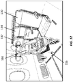
- FIG. 12 depicts an aircraft interior configuration in which the flexible use space is configured to provide passenger seating at the inboard attendant seat position 130, and stroller 166 securement space at the middle and outboard attendant seat positions 134, 132.
- the stroller 166 may be secured in place using at least one restraint assembly 156 secured to the seat tracks 146 of the floor palette 144.
- Exemplary restraint assemblies 156 may include adjustable-length straps.
- the lap belts of the attendant seats can be configured to function as securement straps.
- the lap belt ends may include detachable anchor points such that the ends can detach from their respective anchor points when functioning as a lap belt, and secure to one of the seat tracks of the floor palette and the bulkhead to function as a restraint assembly.
- the lap belt ends may anchor to the lower bulkhead seat track when the lap belt is used as a lap belt and may anchor to the same or other seat tracks when the lap belt is used as a securement strap.
- the lap belts may have an adjustable length and lap belt extensions may be used when securing a large object. Oversized items and items requiring a large distance between attachment points may require dedicated straps having a long length.
- the number of restraint assemblies, type of restraint assemblies, and attachment locations may depend on the item to be secured.
Landscapes
- Engineering & Computer Science (AREA)
- Aviation & Aerospace Engineering (AREA)
- Health & Medical Sciences (AREA)
- Public Health (AREA)
- Life Sciences & Earth Sciences (AREA)
- Animal Behavior & Ethology (AREA)
- General Health & Medical Sciences (AREA)
- Veterinary Medicine (AREA)
- Seats For Vehicles (AREA)
- Mechanical Engineering (AREA)
Abstract
Description
- The present disclosure is generally directed to an aircraft interior configuration including flexible use space, and more particularly, flexible use space in the main cabin reconfigurable to accommodate conventional traveling passengers or those requiring securement space for a wheelchair or other items.
- Conventional traveling passengers are typically able to board a plane on their own and make use of standard aircraft passenger seats. Passengers confined to a wheelchair cannot, and thus require special boarding procedures and accommodations. Part of the special boarding procedures involves transferring a passenger from their own personal wheelchair to a transfer wheelchair able to traverse a narrow aircraft aisle. Such transfer is not only disruptive to the passenger, but transfer wheelchairs are not catered to specific passenger needs and cannot be used for seating during flight. Thus, the passenger must be transferred a second time from the transfer wheelchair to a standard passenger seat, further disrupting the passenger.
- To minimize disruption and better cater to passenger needs, it would be desirable to allow a wheelchair user to remain in their own personal wheelchair during boarding and flight. One obstacle is that aircraft aisles are typically too narrow to accommodate a standard width wheelchair. Another obstacle involves creating space in the main cabin to accommodate and secure a wheelchair. While the first obstacle can potentially be overcome by creating a certified wheelchair having a narrow width, the second obstacle requires an interior cabin configuration able to accommodate and secure in place a wheelchair without abandoning a traditional passenger seating arrangement, and without sacrificing seating density.
- Accordingly, what is needed is an aircraft interior configuration having a flexible use space that can easily be reconfigured to accommodate conventional traveling passengers or wheelchair users, as well as other provide other uses such as care giver seating, storing pet crates, and storing large objects or objects of value.
- In a first aspect, the present invention is directed to an interior configuration for an aircraft including an aisle extending along a longitudinal direction which in use corresponds to a longitudinal axis of the aircraft, a flexible use space disposed laterally adjacent the aisle, a bulkhead disposed at one end of the flexible use space, and attendant seats disposed in the flexible use space affixed to the bulkhead, with each attendant seat comprising a flip-up seat bottom. The flexible use space is reconfigurable between a first configuration in which the attendant seats are used as passenger seats and a second configuration in which at least one seat bottom is flipped up to provide space to receive and secure an item in place on the floor palette. The interior configuration may comprise a floor palette disposed in the flexible use space and including at least one seat track and at least one restraint assembly for securing an item in place of the floor palette. The invention also relates to an aircraft comprising such an interior.
- The attendant seats may include an inboard attendant seat disposed adjacent the aisle, an outboard attendant seat disposed adjacent a fuselage of the aircraft, and a middle attendant seat disposed between the inboard and outboard attendant seats, wherein in the second configuration the seat bottom of the outboard attendant seat is flipped down for use as a seat and the seat bottom of each of the middle and inboard attendant seats is flipped up to provide securement space in the flexible use space to receive and secure in place a wheelchair on the floor palette.
- The bulkhead may be a rear bulkhead disposed perpendicular to the longitudinal direction, and the attendant seats may be disposed laterally adjacent and forward facing.
- In a further aspect, the bulkhead may include at least one seat track for affixing the attendant seats to the bulkhead, and the attendant seats may be free of attachment to the floor palette.
- The floor palette may include at least one seat track disposed perpendicular to the longitudinal axis of the aircraft and at least one seat track disposed parallel to the longitudinal direction.
- The floor palette may, in use, be affixed to the floor of the aircraft and may include at least one recess disposed along an edge thereof positioned in surrounding relation to a leg of a seat disposed adjacent the flexible use space.
- The at least one restraint assembly may include an adjustable length strap having a fastener at each end adapted to engage in the at least one seat track of the floor palette.
- The interior configuration may include passenger seats disposed adjacent the flexible use space, wherein the passenger seats and the attendant seats are disposed in the same facing orientation and are visually similar in appearance.
- Each of the attendant seats may include a frame affixed to the bulkhead and a backrest supported by the frame, and the seat bottom may be pivotably attached to the frame.
- The present invention is directed to an interior configuration for an aircraft including an aisle extending along a longitudinal direction which in use corresponds to a longitudinal axis of the aircraft, a plurality of rows of passenger seats disposed adjacent the aisle, and a rear bulkhead disposed aft of the plurality of rows of passenger seats, wherein a last row of the plurality of rows of passenger seats is disposed in a flexible use space, and each seat in the last row is an attendant seat affixed to the rear bulkhead and includes a flip-up seat bottom, and wherein the flexible use space is reconfigurable between a first configuration in which the attendant seats are used as passenger seats and a second configuration in which at least one seat bottom is flipped up to provide securement space to receive and secure an item in place within the flexible use space.
- The rear bulkhead may include at least one seat track for affixing the attendant seats to the rear bulkhead, and the attendant seats may be free of attachment to the floor palette.
- The floor palette may include at least one seat track disposed perpendicular to the longitudinal direction and at least one seat track disposed parallel to the longitudinal axis of the aircraft.
- The at least one restraint assembly may include an adjustable length strap having a fastener at each end adapted to engage in the at least one seat track of the floor palette.
- The rear bulkhead may be disposed perpendicular to the longitudinal direction and the plurality of rows of seats may be forward facing.
- In a second aspect, the present invention is directed to an interior configuration for an aircraft including a passenger cabin, an aisle disposed within the passenger cabin, a conventional passenger seating area disposed within the passenger cabin, a flexible use space disposed within the passenger cabin adjacent the aisle and the conventional passenger seating area, and a bulkhead disposed adjacent the flexible use space, wherein the flexible use space is reconfigurable between a first configuration for passenger seating and a second configuration providing securement space for an item.
- The interior configuration of the second aspect may include a row of attendant seats disposed in the flexible use space and affixed to the bulkhead, each attendant seat including a flip-up seat bottom movable between a first position for use as a passenger seat and a second position providing securement space forward of the respective attendant seat, a floor palette disposed in the flexible use space including at least one seat track, and at least one restraint assembly configured to secure to the at least one seat track of the floor palette to secure an item in place on the floor palette.
- Embodiments of the present invention can include one or more or any combination of the above aspects, features and configurations.
- Implementations of the present invention may be better understood when consideration is given to the following detailed description thereof. Such description refers to the included drawings, which are not necessarily to scale, and in which some features may be exaggerated, and some features may be omitted or may be represented schematically in the interest of clarity. Like reference numbers in the drawings may represent and refer to the same or similar element, feature, or function. In the drawings:
-
FIG. 1 is a perspective view of a portion of an aircraft interior configuration including flexible use space according to the present invention; -
FIG. 2 is a perspective view of the aircraft interior according toFIG. 1 showing flexible use space configured for securement space for a wheelchair; -
FIG. 3 is a perspective view of flexible use space according toFIG. 1 shown configured to provide securement space; -
FIG. 4 is a perspective view of flexible use space according toFIG. 1 shown configured for securement space for a wheelchair secured to the floor palette; -
FIG. 5 is a side view of flexible use space according toFIG. 1 shown configured for conventional passenger seating; -
FIG. 6 is a front view of the aircraft interior configuration according toFIG. 1 showing consistency among the visual appearance of passenger seats within and outside of a flexible use space; -
FIG. 7 is a perspective view of flexible use space according toFIG. 1 showing a caregiver seat positioned alongside securement space for a wheelchair; -
FIG. 8 is a perspective view of flexible use space according toFIG. 1 configured to provide securement space for two wheelchairs side-by-side; -
FIG. 9 is a perspective view of an aircraft interior configuration according toFIG. 1 showing a bulkhead having seat tracks, a floor palette having seat tracks, and conventional floor seat tracks; -
FIG. 10 is a perspective view of flexible use space shown configured for passenger seating and pet carrier securement; -
FIG. 11 is a perspective view of flexible use space according toFIG. 1 shown configured for passenger seating and large object securement; and -
FIG. 12 is a perspective view of flexible use space according toFIG. 1 shown configured for passenger seating and stroller securement. - The description set forth below in connection with the appended drawings is intended to be a description of various, illustrative embodiments of the disclosed subject matter. Specific features and functionalities are described in connection with each illustrative embodiment; however, it will be apparent to those skilled in the art that the disclosed embodiments may be practiced without each of those specific features and functionalities.
- The aspects, features and functions described below in connection with one embodiment are intended to be applicable to the other embodiments described below except where expressly stated or where an aspect, feature or function is incompatible with an embodiment. Further, the terms "about" and "substantially" with reference to any recited numerical value includes the recited value within a margin of 20%, more preferably 10%, and even more preferably 5%, and any values therebetween.
- Referring to the drawings, disclosed are aspects of an aircraft interior configuration, and particularly, a main passenger cabin configuration having a zone or zones dedicated for conventional passenger seating and a zone or zones providing flexible use space. As used herein, the term "flexible use space" generally refers to space within a passenger seating area readily reconfigurable to provide conventional passenger seating, securement space for a wheelchair, securement space for pet storage, securement space for other items, and combinations thereof. Flexible use space may occupy a portion of a conventional passenger seating zone or may be separate therefrom. In one embodiment, flexible use space may occupy a portion of a conventional passenger seating zone such that the flexible use space is visually indistinguishable from an adjacent conventional passenger seating zone when the flexible use space is used for conventional passenger seating. Certain seat components such as backrests, armrests and headrests may be the same or similar in both the conventional passenger seating zone and the flexible use space for visually consistency throughout the passenger cabin. Flexible use space may be disposed in any location within the aircraft benefitting from the ability to reconfigure between passenger seating and another purpose, including but not limited to, at the rear of the passenger cabin adjacent the lavatory, at the front of the main cabin adjacent a forward bulkhead, in premium class seating areas, in galley areas, etc.
- In one aspect, the flexible use space can be configured to provide conventional passenger seating. In another aspect, the flexible use space can be configured to provide securement space for items. In a further aspect, the flexible use space can be configured to provide both conventional passenger seating and securement space at the same time.
-
FIG. 1 depicts an exemplary aircraftinterior configuration 100 generally includingconventional passenger seating 102 adjacentflexible use space 104. The conventionalpassenger seating space 102 shown includes rows of economy class seats disposed forward facing. Each row ofseats 106 includes three laterally adjacent seats including an inboard seat, an outboard seat, and a middle seat disposed between the inboard and outboard seats. The seat backrests may be recline-capable. Each row ofseats 106 is supported on a frame that secures to the aircraft floor usingconventional seat tracks 108 andtrack fasteners 110. As shown, the seat tracks 108 are disposed parallel to alongitudinal direction 112 that corresponds to thelongitudinal aircraft axis 112 and run substantially the length of the passenger cabin. The aircraftinterior configuration 100 further includes anaircraft aisle 114 disposed parallel to thelongitudinal aircraft axis 112. In an exemplary embodiment, theaircraft aisle 114 is a center aisle that runs the length of the passenger cabin. - The
flexible use space 104 is a dedicated portion of the seating arrangement that can be configured for conventional passenger seating and/or securement space for items. As shown, theflexible use space 104 is disposed aft of the last row of conventional passenger seats and forward of arear bulkhead 116. Therear bulkhead 116 can be disposed adjacent a lavatory, can be a lavatory wall, can divide seating spaces, can be a monument, etc. Theflexible use space 104 is disposed laterally adjacent theaircraft aisle 114 such that theflexible use space 104 is accessible from theaisle 114. Theflexible use space 104 as shown extends between the last row of conventional seats and thebulkhead 116, and from theaisle 114 to thefuselage 118. Other dispositions and configurations are envisioned such as adjacent a forward bulkhead, adjacent a lavatory, adjacent a galley, etc. An aircraft passenger seating arrangement may include one or any number of flexible use spaces in any disposition and within any seating class or classes. - Disposed within the
flexible use space 104 is at least oneattendant seat 120. As used herein, the term "attendant seat" generally refers to a low-profile passenger seat of the type configured to mount in an alternative location as compared to a conventional passenger seat that secures to the floor. Eachattendant seat 120 generally includes aframe 122 configured for wall mounting, abackrest 124 supported by theframe 122, and aseat bottom 126 supported by theframe 122 and/or thebackrest 124. Theseat bottom 126 is a flip-up seat bottom, meaning that the seat bottom is movable or reconfigurable between a use position disposed substantially horizontal and a stowed position disposed generally vertical. In the stowed position, theseat bottom 126 may reside against the front of thebackrest 124 and may lock in place. Theseat bottom 126 may be pivotably attached to theframe 122 or thebackrest 124 to facilitate movement between the use and stowed positions of theseat bottom 126. Eachattendant seat 120 may further include at least onepivoting armrest 128. Eachattendant seat 120 is preferably devoid of legs and/or frame members disposed under the seat bottom that extend into the securement space when the seat bottom is raised. In one embodiment, the attendant seats are free of any direct attachment to the aircraft floor. - The
attendant seats 120 shown inFIG. 1 are arranged as a row of laterally adjacentattendant seats 120 including an inboardattendant seat 130, an outboardattendant seat 132, and a middleattendant seat 134 disposed between the inboard and outboard attendant seats. Other attendant seat configurations are envisioned including 1, 2, 3...n number of attendant seats in various configurations and facing directions. The attendant seats shown are forward facing like the conventional seats for visually consistency throughout the seating class. As such, theflexible use space 104 is visually indistinguishable from the adjacent conventional seating area. The seat pitch between the last row of conventional seats and the row of attendant seats may be consistent with the seat pitch between rows of conventional seats. In an alternative embodiment, the seat pitch between the last row of conventional seats and the row of attendant seats may be greater to better accommodate a wheelchair and/or the storage of large objects. The same or similar backrests, headrests and pivoting armrests may be used in both the conventional passenger seats and the attendant seats for visual consistency. - Seat tracks 136 embedded within or affixed to the forward face of the
rear bulkhead 116 serve to wall mount the attendant seats 120. As shown, the seat tracks 136 include anupper seat track 138 disposed near a top of thebackrests 124, and alower seat track 140 disposed just above thefloor 142. The seat tracks 136 may additionally include a middle seat track disposed between the lower and upper seat tracks. The seat tracks 136 are provided in number and disposition based on one or more of the location and type of attendant seats used, items envisioned to be stowed, wheelchair configurations, etc. The seat tracks 136 allow the attendant seats to mount to a wall, at a height consistent with the adjacent conventional passenger seats, and free of attachment to thefloor 142. Thus, when theseat bottoms 126 are stowed, securement space is provided between the backside of the last row of conventional seats and the stowed attendant seats for receiving and securing items such as a wheelchair, pet carrier, large objects, etc. - Also disposed within the
flexible use space 104 is astructural floor palette 144. Thefloor palette 144 mounts directly to theaircraft floor 142, for example, using the seat tracks 108 in thefloor 142. Thefloor palette 144 includes at least oneseat track 146 embedded within or affixed thereto. As shown, thefloor palette 144 includes first seat tracks 148 disposed proximate the rear end of the floor palette and parallel to the longitudinal aircraft axis, and second seat tracks 150 disposed proximate the forward end of thefloor palette 144 and perpendicular to the longitudinal aircraft axis. As such, the interior configuration includes three separate sets of seat tracks including floor tracks 108 disposed in thefloor 142 for securing the conventional passenger seats and thefloor palette 144, seat tracks 146 disposed in thefloor palette 144 for securing restraint assemblies as discussed in detail below, andseat tracks 136 disposed in thebulkhead 116 for securing the attendant seats 120. - The
floor palette 144 installs within theflexible use space 104 and may be sized to substantially correspond to the square footage of theflexible use space 104. Thefloor palette 144 may be unitary or multi-piece to facilitate installation and depending on the square footage of the flexible use space. Thefloor palette 144 preferably has a lightweight construction, is resistant to deformation, transfer loads on the restraint assemblies to thefloor 142 and has a thin vertical profile to avoid a tripping hazard. - Whereas
FIG. 1 depicts theflexible use space 104 in a configuration for passenger seating,FIG. 2 depicts theflexible use space 104 in a configuration providing securement space for an item, for example, a wheelchair. Securement space is shown generally atreference numeral 152 laterally adjacent theaisle 114 and directly forward of the inboard and middleattendant seats respective seat bottoms 126 in the stowed position. Thus, thesecurement space 152 in this configuration is accessible directly from theaisle 114. Once situated, awheelchair 154 can be secured in place on thefloor palette 144 using one ormore restraint assemblies 156 each generally including anadjustable length strap 158 andfasteners 160 disposed at opposing ends of thestrap 158 configured to engage within the seat tracks 146 of thefloor palette 144. As shown, thewheelchair 154 may be secured in place using one ormore restraint assemblies 156, wherein eachrestraint assembly 156 secures to one of the first and second seat tracks 148 and 150 and around part of the wheelchair.Restraint assemblies 156 may be used on both sides of the wheelchair, for example, securing both wheels.Restraint assemblies 156 may be secured to one or more of the seat tracks in any of the floor, floor palette, and bulkhead. -
FIG. 3 depicts an aircraft interior configuration in which theflexible use space 104 is disposed in a last row of passenger seats immediately forward of therear bulkhead 116. As shown, theseat bottom 126 of the middleattendant seat 134 is in the stowed position, theseat bottom 126 of the inboardattendant seat 130 is in the stowed position, and theseat bottom 126 of the outboardattendant seat 132 is in the use position. Such flexible use space configuration provides securement space forward of the middle and inboardattendant seats FIG. 4 , and a passenger seat at the outboardattendant seat 132 position for a passenger able to use a conventional passenger seat, for example, a caregiver accompanying the wheelchair user.Fig. 4 depicts the seat bottom of the outboardattendant seat 132 removed to provide additional storage space to one side of thesecured wheelchair 154. -
FIG. 5 depicts theflexible use space 104 in a passenger seating configuration in which allattendant seat bottoms 126 are in the use position.FIG. 5 further depicts the shape of thefloor palette 144 to include along the forward edge thereof at least onerecess 162 positioned in surrounding relation to a leg and track fastener of a passenger seat adjacent the flexible use space. Therecesses 162 allow portions of thefloor palette 144 to extend forward of the rear legs of the adjacent row of passenger seats, thereby expanding the flexible use space and locating the first seat tracks 148 farther from the second seat tracks 150 for leverage, to accommodate larger items, etc. -
FIG. 6 depicts an exemplary seating arrangement generally including rows of economy class passenger seats, acenter aisle 114, and arear bulkhead 116 disposed behind the last row of seats. Flexible use space is provided in the last row of seats on one or both sides of theaisle 114. As discussed above, the conventional passenger seats and the attendant seats within the flexible use space may share components to provide visual consistency throughout the cabin, such that to passengers boarding the aircraft it appears as a standard non-accessible interior. -
FIG. 7 depicts an aircraft interior configuration wherein theflexible use space 104 is configured to accommodate a wheelchair user and a caregiver or accompanying passenger seated alongside the secured wheelchair user. -
FIG. 8 depicts an aircraft interior configuration wherein theflexible use space 104 is configured to accommodate two wheelchair users in a side-by-side arrangement, airframe interior space permitting. -
FIG. 9 depicts an exemplarystructural floor palette 144 configuration and the dispositions of the various seat tracks of thefloor palette 144, thefloor 142, and thebulkhead 116. The number and locations of the seat tracks of the floor palette and the bulkhead can be customized to accommodate different attendant seat constructions and envisioned to be secured in the securement space. -
FIG. 10 depicts an aircraft interior configuration in which the flexible use space is configured to provide passenger seating at the inboardattendant seat position 130 and pet carrier securement space at one or more of the middle and outboardattendant seat positions pet carrier 164 may be secured in place using at least onerestraint assembly 156. As shown, thepet carrier 164 is secured in place using twoseparate restraint assemblies 156 installed crisscrossing over the top of the pet carrier, with each restraint assembly secured to separate spaced-apart seat tracks 146 of thefloor palette 144. This restraint assembly configuration can be used to secure an item in place on thefloor palette 144. -
FIG. 11 depicts an aircraft interior configuration in which the flexible use space is configured to provide passenger seating at the inboardattendant seat position 130, and large object (e.g., musical instrument) securement space at one or more of the middle and outboardattendant seat positions large object 166 may be secured in place using at least onerestraint assembly 156 secured to aseat track 146 of thefloor palette 144 and anupper seat track 136 of therear bulkhead 116. The various seat tracks of thefloor palette 144 andbulkhead 116 and dispositions thereof can be used to secure any item in place within the securement space, for example, against the fuselage, against the stowed attendant seats, on the floor palette, etc. -
FIG. 12 depicts an aircraft interior configuration in which the flexible use space is configured to provide passenger seating at the inboardattendant seat position 130, andstroller 166 securement space at the middle and outboardattendant seat positions stroller 166 may be secured in place using at least onerestraint assembly 156 secured to the seat tracks 146 of thefloor palette 144. -
Exemplary restraint assemblies 156 may include adjustable-length straps. Alternatively, the lap belts of the attendant seats can be configured to function as securement straps. For example, the lap belt ends may include detachable anchor points such that the ends can detach from their respective anchor points when functioning as a lap belt, and secure to one of the seat tracks of the floor palette and the bulkhead to function as a restraint assembly. For example, the lap belt ends may anchor to the lower bulkhead seat track when the lap belt is used as a lap belt and may anchor to the same or other seat tracks when the lap belt is used as a securement strap. The lap belts may have an adjustable length and lap belt extensions may be used when securing a large object. Oversized items and items requiring a large distance between attachment points may require dedicated straps having a long length. The number of restraint assemblies, type of restraint assemblies, and attachment locations may depend on the item to be secured. - The foregoing description provides embodiments of the invention by way of example only. It is envisioned that other embodiments may perform similar functions and/or achieve similar results. Such equivalent embodiments and examples may be within the scope of the present invention that is defined by the appended claims.
Claims (15)
- An interior configuration (100) for an aircraft, comprising:an aisle (114) extending along a longitudinal direction (112) which in use corresponds to a longitudinal axis (112) of the aircraft;a flexible use space (104) disposed laterally adjacent the aisle (114);a bulkhead (116) disposed at one end of the flexible use space (104); andattendant seats (130, 132, 134) disposed in the flexible use space (104) affixed to the bulkhead (116), each attendant seat (130, 132, 134) comprising a flip-up seat bottom (126);wherein the flexible use space (104) is reconfigurable between a first configuration in which the attendant seats (130, 132, 134) are used as passenger seats, and a second configuration in which at least one seat bottom (126) is flipped up to provide securement space to receive and secure an item (154, 164, 166) in place on the floor palette (144).
- The interior configuration according to claim 1, further comprising
a floor palette (144) disposed in the flexible use space (104) comprising at least one seat track (148, 150); and
at least one restraint assembly (156) for securing an item in place on the floor palette (144). - The interior configuration according to claim 1 or 2, wherein the attendant seats (120) comprise an inboard attendant seat (130) disposed adjacent the aisle (114), an outboard attendant seat (132) disposed adjacent a fuselage of the aircraft, and a middle attendant seat (134) disposed between the inboard (130) and outboard (132) attendant seats, and wherein in the second configuration the seat bottom (126) of the outboard attendant seat (132) is flipped down for use as a seat and the seat bottom (126) of each of the middle (134) and inboard (130) attendant seats is flipped up to provide securement space in the flexible use space (104) to receive and secure in place a wheelchair (154) on the floor palette (144) using the at least one restraint assembly (156).
- The interior configuration according to one or more of claims 1-3, wherein the bulkhead is a rear bulkhead (116) disposed perpendicular to the longitudinal direction (112), the attendant seats (120) are disposed forward facing, and passenger seats adjacent the flexible use space (104) are disposed forward facing.
- The interior configuration according to one or more of claims 2-4, wherein the bulkhead (116) comprises spaced upper (138) and lower (140) seat tracks, and wherein the attendant seats (120) are free of attachment to the floor palette (144).
- The interior configuration according to one or more of claims 2-5, wherein the floor palette (144) comprises at least one seat track (148) disposed perpendicular to the longitudinal direction (112) and at least one seat track (150) disposed parallel to the longitudinal direction (114), and/or wherein the floor palette (144), in use, is affixed to a floor (142) of the aircraft and comprises at least one recess (162) disposed along an edge thereof positioned in surrounding relation to a leg of a passenger seat disposed adjacent the flexible use space (104).
- The interior configuration according to one or more of claims 2-6, wherein the at least one restraint assembly (156) is an attendant seat lap belt comprising detachable anchor points at opposing ends of an adjustable length strap (158).
- The interior configuration according to one or more of claims 1-7, further comprising passenger seats disposed adjacent the flexible use space (104), wherein the passenger seats and the attendant seats (120) face in a common direction and are visually similar in appearance.
- The interior configuration according to one or more of claims 1-8, wherein each (130, 132, 134) of the attendant seats (120) further comprises a frame (122) affixed to the bulkhead (116) and a backrest (124) supported by the frame (122), and wherein the seat bottom (126) is pivotably attached to the frame (122).
- An interior configuration for an aircraft according to one or more of claims 1-9 comprising:a plurality of rows (106) of passenger seats disposed adjacent the aisle (114); andthe bulkhead being a rear bulkhead (116) being disposed aft of the plurality of rows (106) of passenger seats;wherein a last row (106) of the plurality of rows of passenger seats is disposed in the flexible use space (104), wherein each seat in the last row (106) is an attendant seat (130, 132, 134).
- The interior configuration according to claim 10 and dependent of claim 2, wherein the rear bulkhead (116) comprises at least one seat track (138) to which the attendant seats (120) are affixed, and wherein the attendant seats (120) are free of attachment to the floor palette (144).
- The interior configuration according to one or more of claims 2-11, wherein the at least one restraint assembly (156) comprises an adjustable length strap (158) having a fastener at each end adapted to engage in the at least one seat track (148,150) of the floor palette (144).
- The interior configuration according to one or more of claims 10-12, wherein the rear bulkhead (116) is disposed perpendicular to the longitudinal direction (112), and the plurality of rows (106) of seats are forward facing.
- An interior configuration for an aircraft, comprising:a passenger cabin;an aisle (114) disposed within the passenger cabin;a conventional passenger seating area disposed within the passenger cabin;a flexible use space (104) disposed within the passenger cabin adjacent the aisle (114) and the conventional passenger seating area; anda bulkhead (116) disposed adjacent the flexible use space (104);wherein the flexible use space (104) is reconfigurable between a first configuration for passenger seating and a second configuration providing securement space for an item.
- The interior configuration according to claim 14, further comprising:a row of attendant seats (120) disposed in the flexible use space (104) and affixed to the bulkhead (116), each attendant seat (130, 132, 134) comprising a flip-up seat bottom (126) movable between a first position for use as a passenger seat and a second position providing securement space forward of the respective attendant seat (130, 132, 134); and wherein preferablya floor palette (144) disposed in the flexible use space (104) comprising at least one seat track (148, 150); andat least one restraint assembly (156) configured to secure to the at least one seat track (148, 150) of the floor palette (144) to secure an item (154, 164, 166) in place on the floor palette (144).
Applications Claiming Priority (1)
| Application Number | Priority Date | Filing Date | Title |
|---|---|---|---|
| US16/049,972 US10953987B2 (en) | 2018-07-31 | 2018-07-31 | Aircraft interior configuration with flexible use space |
Publications (2)
| Publication Number | Publication Date |
|---|---|
| EP3608227A1 true EP3608227A1 (en) | 2020-02-12 |
| EP3608227B1 EP3608227B1 (en) | 2023-07-12 |
Family
ID=67514368
Family Applications (1)
| Application Number | Title | Priority Date | Filing Date |
|---|---|---|---|
| EP19189311.4A Active EP3608227B1 (en) | 2018-07-31 | 2019-07-31 | Aircraft interior configuration with flexible use space |
Country Status (2)
| Country | Link |
|---|---|
| US (1) | US10953987B2 (en) |
| EP (1) | EP3608227B1 (en) |
Cited By (4)
| Publication number | Priority date | Publication date | Assignee | Title |
|---|---|---|---|---|
| US10953987B2 (en) | 2018-07-31 | 2021-03-23 | B/E Aerospace, Inc. | Aircraft interior configuration with flexible use space |
| WO2021219693A1 (en) * | 2020-04-30 | 2021-11-04 | Airbus Operations Gmbh | Holding system for a wheelchair in an aircraft |
| EP4227219A1 (en) * | 2022-02-15 | 2023-08-16 | B/E Aerospace, Inc. | Use of forward closet in single aisle aircraft for wheelchair accommodation |
| EP4588799A1 (en) | 2024-01-17 | 2025-07-23 | Airbus Operations GmbH | Transport of passengers with reduced mobility |
Families Citing this family (16)
| Publication number | Priority date | Publication date | Assignee | Title |
|---|---|---|---|---|
| JP7014096B2 (en) * | 2018-08-22 | 2022-02-01 | トヨタ自動車株式会社 | vehicle |
| USD989687S1 (en) * | 2020-11-06 | 2023-06-20 | Rh Us, Llc | Aircraft interior |
| GB2602064B (en) * | 2020-12-17 | 2023-05-10 | Priestman Goode Ltd | Vehicle seat for accommodating a wheelchair |
| USD978549S1 (en) * | 2021-02-19 | 2023-02-21 | Rh Us, Llc | Aircraft interior |
| USD977268S1 (en) * | 2021-02-19 | 2023-02-07 | Rh Us, Llc | Aircraft interior |
| USD1041930S1 (en) * | 2021-02-19 | 2024-09-17 | Rh Us, Llc | Aircraft interior |
| USD1029516S1 (en) * | 2021-02-19 | 2024-06-04 | Rh Us, Llc | Aircraft interior |
| US12214884B2 (en) | 2021-10-01 | 2025-02-04 | B/E Aerospace, Inc. | Expandable lavatory and cabin configuration including dedicated seating area and expandable lavatory |
| US12274651B2 (en) * | 2021-12-08 | 2025-04-15 | Toyota Boshoku Kabushiki Kaisha | Wheelchair restraint apparatus |
| US20240016673A1 (en) * | 2022-07-15 | 2024-01-18 | Supernal, Llc | Systems, methods, and devices for wheelchair restraint |
| US12534203B2 (en) * | 2022-09-15 | 2026-01-27 | B/E Aerospace, Inc. | Person with reduced mobility stretcher and wheelchair monument for aircraft systems |
| US12582564B2 (en) | 2022-09-15 | 2026-03-24 | B/E Aerospace, Inc. | Multi-use aircraft monuments with wheelchair accommodations |
| US20240335046A1 (en) * | 2023-04-06 | 2024-10-10 | Delta Air Lines, Inc. | Adjustable seating area for person with reduced mobility |
| US20240350334A1 (en) * | 2023-04-18 | 2024-10-24 | Delta Air Lines, Inc. | Securing a person with reduced mobility device in a seating area |
| US12515799B2 (en) | 2023-08-03 | 2026-01-06 | B/E Aerospace, Inc. | Wireless power passenger seat |
| US20250269963A1 (en) * | 2024-02-22 | 2025-08-28 | B/E Aerospace, Inc. | Expandable lavatory for full-size wheelchairs |
Citations (4)
| Publication number | Priority date | Publication date | Assignee | Title |
|---|---|---|---|---|
| US6113325A (en) * | 1997-09-29 | 2000-09-05 | Craft; Richard D. | Wheelchair restraint system for a transportation vehicle |
| WO2016157081A1 (en) * | 2015-03-30 | 2016-10-06 | Berro Paolo | Device and transport unit for disabled persons inside a passenger compartment of an aircraft |
| US20170320580A1 (en) * | 2016-05-03 | 2017-11-09 | Airbus Operations Gmbh | Expandable aircraft monument, and aircraft area having an expandable aircraft monument |
| US20190071181A1 (en) * | 2017-09-04 | 2019-03-07 | Airbus Operations Gmbh | Passenger seat arrangement, passenger seat system and aircraft cabin region having a passenger seat arrangement |
Family Cites Families (29)
| Publication number | Priority date | Publication date | Assignee | Title |
|---|---|---|---|---|
| US2556076A (en) * | 1944-09-15 | 1951-06-05 | Robert B Evans | Troopship type airplane seat structure |
| US3314720A (en) * | 1965-02-11 | 1967-04-18 | Millington Ralph | Safety troop seat |
| US4266822A (en) * | 1978-11-15 | 1981-05-12 | American Seating Company | Foldable transportation seat |
| US5026225A (en) | 1988-04-14 | 1991-06-25 | Mcintyre Jack L | Passenger and wheelchair securement system for vehicles |
| US5259575A (en) * | 1992-03-20 | 1993-11-09 | Cabrera Carlos P | Airplane stretcher system |
| US5383629A (en) * | 1992-10-07 | 1995-01-24 | Air Methods Corporation International | Emergency medical system |
| US5769360A (en) * | 1995-03-27 | 1998-06-23 | Research Foundation Of The State University Of New York | Easy transport seat |
| US6691952B2 (en) * | 2001-09-26 | 2004-02-17 | Marvin Keogh | Aircraft medical unit |
| US6923606B2 (en) * | 2002-01-30 | 2005-08-02 | Arinc Incorporated | Medical evacuation patient support pallet |
| US7455490B1 (en) * | 2004-07-21 | 2008-11-25 | Gregory F Goosen | Wheelchair holding device |
| US9616843B2 (en) * | 2004-10-15 | 2017-04-11 | Valeda Company Llc | Barrier with integrated wheelchair restraints |
| US8414234B2 (en) * | 2004-10-15 | 2013-04-09 | Q'Straint | 3-point wheelchair passenger securement system |
| US9107786B2 (en) * | 2008-10-05 | 2015-08-18 | Valeda Company, Llc | 3-point wheelchair passenger securement system |
| US10292879B2 (en) * | 2005-10-17 | 2019-05-21 | Valeda Company, Llc | Wheelchair passenger securement system with bumper |
| US8152101B2 (en) * | 2006-09-12 | 2012-04-10 | Law Sondra F | System and method for integrating handicapped accessible seats into aircraft interior configurations |
| CN102481218B (en) * | 2009-08-18 | 2014-09-03 | 丰田车体株式会社 | Wheelchair seat belt device |
| DE102009056188A1 (en) * | 2009-11-27 | 2011-06-01 | Airbus Operations Gmbh | Aircraft seat arrangement for aircraft passengers with reduced mobility |
| US8911188B1 (en) * | 2013-05-24 | 2014-12-16 | Franz Kiel Gmbh | Double folding seat for a vehicle |
| EP2886447A1 (en) * | 2013-12-18 | 2015-06-24 | Airbus Operations, S.L. | A double-deck airplane |
| EP2927127B1 (en) * | 2014-04-04 | 2020-10-14 | Airbus Operations GmbH | Apparatus for holding a cabin attendant seat, cabin arrangement in a vehicle and vehicle having a cabin and such a cabin arrangement |
| EP2927125B1 (en) * | 2014-04-04 | 2020-10-21 | Airbus Operations GmbH | Partition element for an aircraft cabin and cabin arrangement |
| EP2939920B1 (en) * | 2014-04-29 | 2021-10-13 | Airbus Operations GmbH | Deployable floor panel arrangement for aircraft cabin area |
| US9504617B2 (en) * | 2014-07-15 | 2016-11-29 | 4One, Llc | Mobility securement system |
| US9585800B2 (en) * | 2014-07-15 | 2017-03-07 | 4One, Llc | Mobility securement system |
| US9688165B2 (en) * | 2015-07-10 | 2017-06-27 | Franz Kiel Gmbh | Seat assembly for a vehicle |
| US9833367B2 (en) * | 2015-08-28 | 2017-12-05 | Franz Kiel Gmbh | Modular element for a vehicle |
| US10130529B2 (en) * | 2016-02-16 | 2018-11-20 | Indiana Mills & Manufacturing, Inc. | Apparatus for mounting wheelchair securement devices to existing vehicle seat mounting structures |
| US10285880B1 (en) * | 2017-11-09 | 2019-05-14 | Ford Global Technologies, Llc | Wheelchair dock |
| US10953987B2 (en) | 2018-07-31 | 2021-03-23 | B/E Aerospace, Inc. | Aircraft interior configuration with flexible use space |
-
2018
- 2018-07-31 US US16/049,972 patent/US10953987B2/en active Active
-
2019
- 2019-07-31 EP EP19189311.4A patent/EP3608227B1/en active Active
Patent Citations (4)
| Publication number | Priority date | Publication date | Assignee | Title |
|---|---|---|---|---|
| US6113325A (en) * | 1997-09-29 | 2000-09-05 | Craft; Richard D. | Wheelchair restraint system for a transportation vehicle |
| WO2016157081A1 (en) * | 2015-03-30 | 2016-10-06 | Berro Paolo | Device and transport unit for disabled persons inside a passenger compartment of an aircraft |
| US20170320580A1 (en) * | 2016-05-03 | 2017-11-09 | Airbus Operations Gmbh | Expandable aircraft monument, and aircraft area having an expandable aircraft monument |
| US20190071181A1 (en) * | 2017-09-04 | 2019-03-07 | Airbus Operations Gmbh | Passenger seat arrangement, passenger seat system and aircraft cabin region having a passenger seat arrangement |
Cited By (7)
| Publication number | Priority date | Publication date | Assignee | Title |
|---|---|---|---|---|
| US10953987B2 (en) | 2018-07-31 | 2021-03-23 | B/E Aerospace, Inc. | Aircraft interior configuration with flexible use space |
| WO2021219693A1 (en) * | 2020-04-30 | 2021-11-04 | Airbus Operations Gmbh | Holding system for a wheelchair in an aircraft |
| EP4488177A3 (en) * | 2020-04-30 | 2025-03-19 | AIRBUS Operations GmbH | Holding system for a wheelchair in an aircraft |
| US12465534B2 (en) | 2020-04-30 | 2025-11-11 | Airbus Operations Gmbh | Holding system for a wheelchair in an aircraft |
| EP4227219A1 (en) * | 2022-02-15 | 2023-08-16 | B/E Aerospace, Inc. | Use of forward closet in single aisle aircraft for wheelchair accommodation |
| EP4588799A1 (en) | 2024-01-17 | 2025-07-23 | Airbus Operations GmbH | Transport of passengers with reduced mobility |
| US12575982B2 (en) | 2024-01-17 | 2026-03-17 | Airbus Operations Gmbh | Transport of passengers with reduced mobility |
Also Published As
| Publication number | Publication date |
|---|---|
| US20200039626A1 (en) | 2020-02-06 |
| EP3608227B1 (en) | 2023-07-12 |
| US10953987B2 (en) | 2021-03-23 |
Similar Documents
| Publication | Publication Date | Title |
|---|---|---|
| US10953987B2 (en) | Aircraft interior configuration with flexible use space | |
| EP3439957B1 (en) | Contoured class divider | |
| US7025306B2 (en) | Individual module for aircraft passengers | |
| US10676194B2 (en) | Contoured class divider | |
| EP3680173B1 (en) | Passenger seat reconfigurable for seating or storage | |
| EP3526120B1 (en) | Contoured class divider | |
| US20070241232A1 (en) | Seating for a Passenger Vehicle | |
| EP3636548B1 (en) | Vehicle business class seat and stowage system | |
| US11673671B2 (en) | Passenger seating arrangement | |
| EP3233636B1 (en) | Lavatory, first class, and business class seat integration | |
| CN113165747B (en) | Business class seats for passenger transport | |
| US8851568B2 (en) | Retractable passenger seat | |
| US12600480B2 (en) | Vehicle passenger seat assembly | |
| EP3647195B1 (en) | Aisle access side facing seat | |
| US10611483B2 (en) | Passenger seat arrangement for a transport vehicle | |
| EP4015385B1 (en) | Aircraft passenger seat row with cabin attendant seat | |
| US20260054838A1 (en) | Vip front row business class monument |
Legal Events
| Date | Code | Title | Description |
|---|---|---|---|
| PUAI | Public reference made under article 153(3) epc to a published international application that has entered the european phase |
Free format text: ORIGINAL CODE: 0009012 |
|
| STAA | Information on the status of an ep patent application or granted ep patent |
Free format text: STATUS: THE APPLICATION HAS BEEN PUBLISHED |
|
| AK | Designated contracting states |
Kind code of ref document: A1 Designated state(s): AL AT BE BG CH CY CZ DE DK EE ES FI FR GB GR HR HU IE IS IT LI LT LU LV MC MK MT NL NO PL PT RO RS SE SI SK SM TR |
|
| AX | Request for extension of the european patent |
Extension state: BA ME |
|
| STAA | Information on the status of an ep patent application or granted ep patent |
Free format text: STATUS: REQUEST FOR EXAMINATION WAS MADE |
|
| 17P | Request for examination filed |
Effective date: 20200803 |
|
| RBV | Designated contracting states (corrected) |
Designated state(s): AL AT BE BG CH CY CZ DE DK EE ES FI FR GB GR HR HU IE IS IT LI LT LU LV MC MK MT NL NO PL PT RO RS SE SI SK SM TR |
|
| STAA | Information on the status of an ep patent application or granted ep patent |
Free format text: STATUS: EXAMINATION IS IN PROGRESS |
|
| 17Q | First examination report despatched |
Effective date: 20211130 |
|
| GRAP | Despatch of communication of intention to grant a patent |
Free format text: ORIGINAL CODE: EPIDOSNIGR1 |
|
| STAA | Information on the status of an ep patent application or granted ep patent |
Free format text: STATUS: GRANT OF PATENT IS INTENDED |
|
| INTG | Intention to grant announced |
Effective date: 20230328 |
|
| GRAS | Grant fee paid |
Free format text: ORIGINAL CODE: EPIDOSNIGR3 |
|
| GRAA | (expected) grant |
Free format text: ORIGINAL CODE: 0009210 |
|
| STAA | Information on the status of an ep patent application or granted ep patent |
Free format text: STATUS: THE PATENT HAS BEEN GRANTED |
|
| AK | Designated contracting states |
Kind code of ref document: B1 Designated state(s): AL AT BE BG CH CY CZ DE DK EE ES FI FR GB GR HR HU IE IS IT LI LT LU LV MC MK MT NL NO PL PT RO RS SE SI SK SM TR |
|
| REG | Reference to a national code |
Ref country code: CH Ref legal event code: EP |
|
| P01 | Opt-out of the competence of the unified patent court (upc) registered |
Effective date: 20230608 |
|
| REG | Reference to a national code |
Ref country code: IE Ref legal event code: FG4D |
|
| REG | Reference to a national code |
Ref country code: DE Ref legal event code: R096 Ref document number: 602019032432 Country of ref document: DE |
|
| REG | Reference to a national code |
Ref country code: LT Ref legal event code: MG9D |
|
| REG | Reference to a national code |
Ref country code: NL Ref legal event code: MP Effective date: 20230712 |
|
| REG | Reference to a national code |
Ref country code: AT Ref legal event code: MK05 Ref document number: 1586886 Country of ref document: AT Kind code of ref document: T Effective date: 20230712 |
|
| PG25 | Lapsed in a contracting state [announced via postgrant information from national office to epo] |
Ref country code: NL Free format text: LAPSE BECAUSE OF FAILURE TO SUBMIT A TRANSLATION OF THE DESCRIPTION OR TO PAY THE FEE WITHIN THE PRESCRIBED TIME-LIMIT Effective date: 20230712 |
|
| PG25 | Lapsed in a contracting state [announced via postgrant information from national office to epo] |
Ref country code: GR Free format text: LAPSE BECAUSE OF FAILURE TO SUBMIT A TRANSLATION OF THE DESCRIPTION OR TO PAY THE FEE WITHIN THE PRESCRIBED TIME-LIMIT Effective date: 20231013 |
|
| PG25 | Lapsed in a contracting state [announced via postgrant information from national office to epo] |
Ref country code: ES Free format text: LAPSE BECAUSE OF FAILURE TO SUBMIT A TRANSLATION OF THE DESCRIPTION OR TO PAY THE FEE WITHIN THE PRESCRIBED TIME-LIMIT Effective date: 20230712 |
|
| PG25 | Lapsed in a contracting state [announced via postgrant information from national office to epo] |
Ref country code: IS Free format text: LAPSE BECAUSE OF FAILURE TO SUBMIT A TRANSLATION OF THE DESCRIPTION OR TO PAY THE FEE WITHIN THE PRESCRIBED TIME-LIMIT Effective date: 20231112 |
|
| PG25 | Lapsed in a contracting state [announced via postgrant information from national office to epo] |
Ref country code: SE Free format text: LAPSE BECAUSE OF FAILURE TO SUBMIT A TRANSLATION OF THE DESCRIPTION OR TO PAY THE FEE WITHIN THE PRESCRIBED TIME-LIMIT Effective date: 20230712 Ref country code: RS Free format text: LAPSE BECAUSE OF FAILURE TO SUBMIT A TRANSLATION OF THE DESCRIPTION OR TO PAY THE FEE WITHIN THE PRESCRIBED TIME-LIMIT Effective date: 20230712 Ref country code: PT Free format text: LAPSE BECAUSE OF FAILURE TO SUBMIT A TRANSLATION OF THE DESCRIPTION OR TO PAY THE FEE WITHIN THE PRESCRIBED TIME-LIMIT Effective date: 20231113 Ref country code: NO Free format text: LAPSE BECAUSE OF FAILURE TO SUBMIT A TRANSLATION OF THE DESCRIPTION OR TO PAY THE FEE WITHIN THE PRESCRIBED TIME-LIMIT Effective date: 20231012 Ref country code: LV Free format text: LAPSE BECAUSE OF FAILURE TO SUBMIT A TRANSLATION OF THE DESCRIPTION OR TO PAY THE FEE WITHIN THE PRESCRIBED TIME-LIMIT Effective date: 20230712 Ref country code: LT Free format text: LAPSE BECAUSE OF FAILURE TO SUBMIT A TRANSLATION OF THE DESCRIPTION OR TO PAY THE FEE WITHIN THE PRESCRIBED TIME-LIMIT Effective date: 20230712 Ref country code: IS Free format text: LAPSE BECAUSE OF FAILURE TO SUBMIT A TRANSLATION OF THE DESCRIPTION OR TO PAY THE FEE WITHIN THE PRESCRIBED TIME-LIMIT Effective date: 20231112 Ref country code: HR Free format text: LAPSE BECAUSE OF FAILURE TO SUBMIT A TRANSLATION OF THE DESCRIPTION OR TO PAY THE FEE WITHIN THE PRESCRIBED TIME-LIMIT Effective date: 20230712 Ref country code: GR Free format text: LAPSE BECAUSE OF FAILURE TO SUBMIT A TRANSLATION OF THE DESCRIPTION OR TO PAY THE FEE WITHIN THE PRESCRIBED TIME-LIMIT Effective date: 20231013 Ref country code: FI Free format text: LAPSE BECAUSE OF FAILURE TO SUBMIT A TRANSLATION OF THE DESCRIPTION OR TO PAY THE FEE WITHIN THE PRESCRIBED TIME-LIMIT Effective date: 20230712 Ref country code: ES Free format text: LAPSE BECAUSE OF FAILURE TO SUBMIT A TRANSLATION OF THE DESCRIPTION OR TO PAY THE FEE WITHIN THE PRESCRIBED TIME-LIMIT Effective date: 20230712 Ref country code: AT Free format text: LAPSE BECAUSE OF FAILURE TO SUBMIT A TRANSLATION OF THE DESCRIPTION OR TO PAY THE FEE WITHIN THE PRESCRIBED TIME-LIMIT Effective date: 20230712 |
|
| PG25 | Lapsed in a contracting state [announced via postgrant information from national office to epo] |
Ref country code: PL Free format text: LAPSE BECAUSE OF FAILURE TO SUBMIT A TRANSLATION OF THE DESCRIPTION OR TO PAY THE FEE WITHIN THE PRESCRIBED TIME-LIMIT Effective date: 20230712 |
|
| REG | Reference to a national code |
Ref country code: CH Ref legal event code: PL |
|
| REG | Reference to a national code |
Ref country code: BE Ref legal event code: MM Effective date: 20230731 |
|
| PG25 | Lapsed in a contracting state [announced via postgrant information from national office to epo] |
Ref country code: LU Free format text: LAPSE BECAUSE OF NON-PAYMENT OF DUE FEES Effective date: 20230731 |
|
| PG25 | Lapsed in a contracting state [announced via postgrant information from national office to epo] |
Ref country code: LU Free format text: LAPSE BECAUSE OF NON-PAYMENT OF DUE FEES Effective date: 20230731 |
|
| REG | Reference to a national code |
Ref country code: DE Ref legal event code: R097 Ref document number: 602019032432 Country of ref document: DE |
|
| REG | Reference to a national code |
Ref country code: IE Ref legal event code: MM4A |
|
| PG25 | Lapsed in a contracting state [announced via postgrant information from national office to epo] |
Ref country code: SM Free format text: LAPSE BECAUSE OF FAILURE TO SUBMIT A TRANSLATION OF THE DESCRIPTION OR TO PAY THE FEE WITHIN THE PRESCRIBED TIME-LIMIT Effective date: 20230712 Ref country code: RO Free format text: LAPSE BECAUSE OF FAILURE TO SUBMIT A TRANSLATION OF THE DESCRIPTION OR TO PAY THE FEE WITHIN THE PRESCRIBED TIME-LIMIT Effective date: 20230712 Ref country code: EE Free format text: LAPSE BECAUSE OF FAILURE TO SUBMIT A TRANSLATION OF THE DESCRIPTION OR TO PAY THE FEE WITHIN THE PRESCRIBED TIME-LIMIT Effective date: 20230712 Ref country code: DK Free format text: LAPSE BECAUSE OF FAILURE TO SUBMIT A TRANSLATION OF THE DESCRIPTION OR TO PAY THE FEE WITHIN THE PRESCRIBED TIME-LIMIT Effective date: 20230712 Ref country code: CZ Free format text: LAPSE BECAUSE OF FAILURE TO SUBMIT A TRANSLATION OF THE DESCRIPTION OR TO PAY THE FEE WITHIN THE PRESCRIBED TIME-LIMIT Effective date: 20230712 Ref country code: MC Free format text: LAPSE BECAUSE OF FAILURE TO SUBMIT A TRANSLATION OF THE DESCRIPTION OR TO PAY THE FEE WITHIN THE PRESCRIBED TIME-LIMIT Effective date: 20230712 Ref country code: CH Free format text: LAPSE BECAUSE OF NON-PAYMENT OF DUE FEES Effective date: 20230731 Ref country code: SK Free format text: LAPSE BECAUSE OF FAILURE TO SUBMIT A TRANSLATION OF THE DESCRIPTION OR TO PAY THE FEE WITHIN THE PRESCRIBED TIME-LIMIT Effective date: 20230712 |
|
| PLBE | No opposition filed within time limit |
Free format text: ORIGINAL CODE: 0009261 |
|
| STAA | Information on the status of an ep patent application or granted ep patent |
Free format text: STATUS: NO OPPOSITION FILED WITHIN TIME LIMIT |
|
| PG25 | Lapsed in a contracting state [announced via postgrant information from national office to epo] |
Ref country code: IT Free format text: LAPSE BECAUSE OF FAILURE TO SUBMIT A TRANSLATION OF THE DESCRIPTION OR TO PAY THE FEE WITHIN THE PRESCRIBED TIME-LIMIT Effective date: 20230712 Ref country code: BE Free format text: LAPSE BECAUSE OF NON-PAYMENT OF DUE FEES Effective date: 20230731 |
|
| 26N | No opposition filed |
Effective date: 20240415 |
|
| PG25 | Lapsed in a contracting state [announced via postgrant information from national office to epo] |
Ref country code: IE Free format text: LAPSE BECAUSE OF NON-PAYMENT OF DUE FEES Effective date: 20230731 |
|
| PG25 | Lapsed in a contracting state [announced via postgrant information from national office to epo] |
Ref country code: IE Free format text: LAPSE BECAUSE OF NON-PAYMENT OF DUE FEES Effective date: 20230731 Ref country code: SI Free format text: LAPSE BECAUSE OF FAILURE TO SUBMIT A TRANSLATION OF THE DESCRIPTION OR TO PAY THE FEE WITHIN THE PRESCRIBED TIME-LIMIT Effective date: 20230712 |
|
| PG25 | Lapsed in a contracting state [announced via postgrant information from national office to epo] |
Ref country code: BG Free format text: LAPSE BECAUSE OF FAILURE TO SUBMIT A TRANSLATION OF THE DESCRIPTION OR TO PAY THE FEE WITHIN THE PRESCRIBED TIME-LIMIT Effective date: 20230712 |
|
| PG25 | Lapsed in a contracting state [announced via postgrant information from national office to epo] |
Ref country code: BG Free format text: LAPSE BECAUSE OF FAILURE TO SUBMIT A TRANSLATION OF THE DESCRIPTION OR TO PAY THE FEE WITHIN THE PRESCRIBED TIME-LIMIT Effective date: 20230712 |
|
| PGFP | Annual fee paid to national office [announced via postgrant information from national office to epo] |
Ref country code: GB Payment date: 20250619 Year of fee payment: 7 |
|
| PGFP | Annual fee paid to national office [announced via postgrant information from national office to epo] |
Ref country code: FR Payment date: 20250620 Year of fee payment: 7 |
|
| PG25 | Lapsed in a contracting state [announced via postgrant information from national office to epo] |
Ref country code: CY Free format text: LAPSE BECAUSE OF FAILURE TO SUBMIT A TRANSLATION OF THE DESCRIPTION OR TO PAY THE FEE WITHIN THE PRESCRIBED TIME-LIMIT; INVALID AB INITIO Effective date: 20190731 |
|
| PG25 | Lapsed in a contracting state [announced via postgrant information from national office to epo] |
Ref country code: HU Free format text: LAPSE BECAUSE OF FAILURE TO SUBMIT A TRANSLATION OF THE DESCRIPTION OR TO PAY THE FEE WITHIN THE PRESCRIBED TIME-LIMIT; INVALID AB INITIO Effective date: 20190731 |
|
| PGFP | Annual fee paid to national office [announced via postgrant information from national office to epo] |
Ref country code: DE Payment date: 20250620 Year of fee payment: 7 |
|
| PG25 | Lapsed in a contracting state [announced via postgrant information from national office to epo] |
Ref country code: TR Free format text: LAPSE BECAUSE OF FAILURE TO SUBMIT A TRANSLATION OF THE DESCRIPTION OR TO PAY THE FEE WITHIN THE PRESCRIBED TIME-LIMIT Effective date: 20230712 |