EP3608183A1 - An adapter for an integrated unit with a bleed valve, a temperature sensor and a pressure sensor for a brake caliper - Google Patents
An adapter for an integrated unit with a bleed valve, a temperature sensor and a pressure sensor for a brake caliper Download PDFInfo
- Publication number
- EP3608183A1 EP3608183A1 EP19189833.7A EP19189833A EP3608183A1 EP 3608183 A1 EP3608183 A1 EP 3608183A1 EP 19189833 A EP19189833 A EP 19189833A EP 3608183 A1 EP3608183 A1 EP 3608183A1
- Authority
- EP
- European Patent Office
- Prior art keywords
- seat
- adapter
- bleed
- threaded
- internal cavity
- Prior art date
- Legal status (The legal status is an assumption and is not a legal conclusion. Google has not performed a legal analysis and makes no representation as to the accuracy of the status listed.)
- Granted
Links
Images

Classifications
-
- B—PERFORMING OPERATIONS; TRANSPORTING
- B60—VEHICLES IN GENERAL
- B60T—VEHICLE BRAKE CONTROL SYSTEMS OR PARTS THEREOF; BRAKE CONTROL SYSTEMS OR PARTS THEREOF, IN GENERAL; ARRANGEMENT OF BRAKING ELEMENTS ON VEHICLES IN GENERAL; PORTABLE DEVICES FOR PREVENTING UNWANTED MOVEMENT OF VEHICLES; VEHICLE MODIFICATIONS TO FACILITATE COOLING OF BRAKES
- B60T11/00—Transmitting braking action from initiating means to ultimate brake actuator without power assistance or drive or where such assistance or drive is irrelevant
- B60T11/10—Transmitting braking action from initiating means to ultimate brake actuator without power assistance or drive or where such assistance or drive is irrelevant transmitting by fluid means, e.g. hydraulic
- B60T11/28—Valves specially adapted therefor
- B60T11/30—Bleed valves for hydraulic brake systems
-
- B—PERFORMING OPERATIONS; TRANSPORTING
- B60—VEHICLES IN GENERAL
- B60T—VEHICLE BRAKE CONTROL SYSTEMS OR PARTS THEREOF; BRAKE CONTROL SYSTEMS OR PARTS THEREOF, IN GENERAL; ARRANGEMENT OF BRAKING ELEMENTS ON VEHICLES IN GENERAL; PORTABLE DEVICES FOR PREVENTING UNWANTED MOVEMENT OF VEHICLES; VEHICLE MODIFICATIONS TO FACILITATE COOLING OF BRAKES
- B60T17/00—Component parts, details, or accessories of power brake systems not covered by groups B60T8/00, B60T13/00 or B60T15/00, or presenting other characteristic features
- B60T17/18—Safety devices; Monitoring
- B60T17/22—Devices for monitoring or checking brake systems; Signal devices
- B60T17/221—Procedure or apparatus for checking or keeping in a correct functioning condition of brake systems
- B60T17/222—Procedure or apparatus for checking or keeping in a correct functioning condition of brake systems by filling or bleeding of hydraulic systems
Definitions
- the present invention concerns an adapter for an integrated unit with a bleed valve, a temperature sensor and a pressure sensor for a brake caliper.
- the braking system and in particular the brake fluid circuit, must in effect be sized in such a way that the temperature of the brake fluid never reaches, even in particularly severe conditions, the maximum allowable temperature, beyond which the fluid vaporizes. Being compressible, gaseous substances such as fluid vapors and air that may be trapped in the brake fluid do not allow the pressure required for applying the brakes to be transmitted.
- the brake fluid temperature of a vehicle braking system is measured by means of a thermocouple applied in a threaded seat with a conical end provided in an upper part of the brake caliper.
- the threaded seat houses a hollow bleed screw.
- the bleed screw is penetrated by a central channel that serves to remove air bubbles from the brake fluid.
- the thermocouple is mounted in the threaded seat for the bleed screw by means of a threaded fastening element with a conical end of a shape and size corresponding to that of the bleed screw.
- the bleed screw To apply the thermocouple, the bleed screw must first be removed from its seat in the brake caliper, then a first bleed step is carried out, then the thermocouple is applied and the threaded fastener that carries the thermocouple is tightened. Once the test has been completed and the temperature has been measured, the thermocouple must be removed, a second bleed operation must be carried out, and the bleed screw must be remounted on the brake caliper.
- a pressure sensor is currently applied upstream of the brake caliper, at an intermediate point of the braking system interposed between a rigid supply tube and a flexible tube that brings the brake fluid to the caliper.
- a T-connector three-way is introduced, which allows the passage of the brake fluid and also allows a pressure transducer to be connected. Therefore, to apply the pressure transducer, the hydraulic circuit is opened again, causing the introduction of considerable quantities of air into the braking circuit.
- Part of the air entering the circuit migrates through the flexible tube towards the brake caliper; another part of the air entering the circuit rises through the rigid tube towards the hydraulic control unit, which is located in the engine compartment in a higher position than the brake caliper and at the point where the connection for the pressure sensor is inserted.
- Each bleed procedure requires a certain number of bleed cycles to completely remove the air. It is necessary to carry out several subsequent bleed cycles and wait each time for the air bubbles dispersed inside the tubes to recompose after each bleed cycle to form larger air bubbles, which are easier to expel.
- a general object of the present invention is to overcome the aforementioned inconveniences by measuring the temperature and pressure of the brake fluid in a simpler and more expeditious way. Another object is to avoid or at least drastically reduce the introduction of air into the circuit of the braking system.
- the present invention proposes to make an adapter for an integrated unit with bleed valve, temperature sensor and pressure sensor for a brake caliper; the adapter allows both for bleeding the brake fluid and for measuring its temperature and pressure without having to disconnect the conduits of the hydraulic circuit of the braking system.
- an adapter has a hollow body, which forms an internal cavity, and a connecting appendage, which has an external thread and an internal passage. This passage opens at one end of the connecting appendage and is in fluid communication with the internal cavity.
- Two threaded seats are formed in the hollow body, both open externally and both in fluid communication with the internal cavity.
- a first threaded seat is configured to receive at least one temperature and/or pressure transducer.
- a second seat is configured to receive a bleed screw and has a conical end connection surface tapering towards and communicating with the internal cavity.
- an adapter indicated collectively at number 10, comprises a hollow body 11 that forms an internal cavity 12.
- the hollow body 11 is made of rigid material, preferably of metallic material.
- the hollow body 11 may be made of aluminum or aluminum alloys, which may withstand temperature peaks (800°C-1000°C) due to the proximity of the brake disc.
- the hollow body 11 forms a connecting appendage 13 penetrated by an internal passage 14 that opens externally and is in fluid communication with the internal cavity 12 of the hollow body 11.
- the connecting appendage 13 has a cylindrical portion 15 with an external thread 16, which allows screwing into a corresponding threaded bleed seat A formed in the body B of a brake caliper ( Figure 8 ), to which the adapter is to be mounted.
- the threaded bleed seat A of the brake caliper is the seat into which a traditional bleed screw may be screwed.
- the bleed seat A is closed by a threaded plug (not shown).
- the connecting appendage 13 may have a conical end portion 17, as in the embodiment illustrated, corresponding to a traditional conical surface in the bleed seat A of the brake caliper.
- the connecting appendage 13 allows the adapter to be mounted in the bleed seat A of the brake caliper.
- the internal passage 14 allows the brake fluid from the body B of the brake caliper to be introduced into the cavity 12 of the adapter.
- the body 11 of the adapter forms at least two cylindrical seats with respective internal threads: a first cylindrical seat 18 with an internal thread 19 and a second cylindrical seat 20 with an internal thread 21. Both seats 18 and 20 open to the outside and are in fluid communication with the internal cavity 12.
- At least one of the seats 18, 20 has a respective conical end connection surface 22, 23, tapered towards the cavity 12 and communicating therewith.
- the first seat 18 is configured to receive a bleed screw 24 ( Figures 5 and 6 ) suitable to allow the removal of air and vapor bubbles from the brake fluid contained in the cavity 12 and originating from the hydraulic circuit that activates the brake caliper.
- the bleed screw 24 has a structure that does not differ significantly from a traditional bleed screw and has a conical end 25 coupled with or corresponding to the conical end connection portion 20 of the seat 18. According to a configuration known per se, the bleed screw 24 may have a longitudinal channel 26 which opens at one end of the screw intended in use to be turned outwards, and a transverse channel 27 which opens near the conical end 25 and communicates with the longitudinal channel 25.
- the outer part of the bleed screw 24 may be miniaturized for reasons of space so that it does not protrude appreciably from the adapter when mounted thereto.
- the second threaded seat 20 is configured to receive a pressure transducer 28 with integrated temperature sensor to measure the temperature and pressure of the brake fluid introduced into the cavity 12.
- the integrated transducer 28 is known in the art and does not need to be described in detail here.
- an integrated transducer sold by Kulite Semiconductor Products, Inc. may be installed.
- the transducer 28 may be connected electrically, by means of a cable 29, to a connector 30 containing the electronics for power supply and management of the temperature and pressure sensors.
- the connector 30 is preferably fitted in the wheel arch of the motor vehicle, where the operating temperatures are lower than in the brake area.
- the connecting appendage When the adapter 10 is mounted on the brake caliper, the connecting appendage is turned downwards and inserted into the bleed seat A, while the threaded seats 18, 20 are turned upwards.
- the seats 18, 20 may be identical in shape and size, which allows the integrated transducer or the bleed valve to be mounted indifferently in either seat 18, 20.
- the measurement and bleed operations may be carried out as follows. First of all, the external closure plug, which normally closes the circuit, is removed from the seat A of the brake caliper. Then the connecting appendage 13 of the adapter is screwed into the seat A of the caliper. An integrated pressure-temperature transducer 28 is mounted in the first threaded seat 18 of the adapter. A bleed screw 24 is mounted in the second seat 20. The connector 30 is applied and connected electrically to an electronic control unit (not shown), conveniently located in a not excessively hot area of the vehicle to be tested, typically in the wheel arch. The air in the circuit is then removed by acting on the bleed screw 24, which is then closed.
- the test may then be carried out by measuring the temperature and the pressure of the brake fluid through the transducer 28. After the measurements have been made, the connector 30 is disconnected, and the adapter 10 is removed from the seat A of the brake caliper. A final bleed phase of the brake fluid is carried out; this bleed phase may be carried out by applying a traditional bleed screw in the seat A of the brake caliper, or the same bleed screw 24 unscrewed from the adapter 10.
- the pressure and temperature of the brake fluid in a braking system may be measured without disconnecting the conduits of the hydraulic circuit.
- Experimental tests carried out by the Applicant have shown that the use of an adapter as described above allows an overall reduction in the preparation and testing time of approximately 50%. It will be appreciated that the risk of air being introduced into the braking system and trapped therein is eliminated. Possible complications linked, according to the traditional art, to disconnecting the hydraulic circuit at a height from which any air bubbles introduced into the circuit tended to go up towards the hydraulic control unit of the vehicle, are eliminated.
- the small size of the adapter allows it to be mounted on virtually any brake caliper, without problems of interference with mechanical members close to the brake caliper.
- the internal cavity 12 may be obtained as an internal chamber 12 communicating on one side with the internal passage 14 and communicating directly, on the other side, with the threaded seats 18, 20.
- the internal cavity 12 may be obtained in the form of a branched channel obtained within the body 11 of the adapter.
- the channel may comprise two conduits 12a, 12b that fork from the internal passage 14 and connect it respectively to the first 18 and the second seat 20.
- the adapter may have two separate and distinct threaded seats instead of a single threaded seat for a single integrated temperature and pressure transducer.
- a first seat may be used to mount a pressure sensor and a second threaded seat may be used to mount a temperature sensor.
Landscapes
- Engineering & Computer Science (AREA)
- Transportation (AREA)
- Mechanical Engineering (AREA)
- Braking Arrangements (AREA)
- Valves And Accessory Devices For Braking Systems (AREA)
- Measuring Temperature Or Quantity Of Heat (AREA)
Abstract
Description
- The present invention concerns an adapter for an integrated unit with a bleed valve, a temperature sensor and a pressure sensor for a brake caliper.
- As is well known, during the development and testing operations of the brakes of a new motor vehicle, it is necessary to measure the temperature and pressure of the brake fluid. The braking system, and in particular the brake fluid circuit, must in effect be sized in such a way that the temperature of the brake fluid never reaches, even in particularly severe conditions, the maximum allowable temperature, beyond which the fluid vaporizes. Being compressible, gaseous substances such as fluid vapors and air that may be trapped in the brake fluid do not allow the pressure required for applying the brakes to be transmitted.
- Currently, the brake fluid temperature of a vehicle braking system is measured by means of a thermocouple applied in a threaded seat with a conical end provided in an upper part of the brake caliper. In normal vehicle use, the threaded seat houses a hollow bleed screw. The bleed screw is penetrated by a central channel that serves to remove air bubbles from the brake fluid. In the test phase, the thermocouple is mounted in the threaded seat for the bleed screw by means of a threaded fastening element with a conical end of a shape and size corresponding to that of the bleed screw.
- Whenever the hydraulic circuit of the braking system is opened, a bleed is required before closing the circuit.
- To apply the thermocouple, the bleed screw must first be removed from its seat in the brake caliper, then a first bleed step is carried out, then the thermocouple is applied and the threaded fastener that carries the thermocouple is tightened. Once the test has been completed and the temperature has been measured, the thermocouple must be removed, a second bleed operation must be carried out, and the bleed screw must be remounted on the brake caliper.
- To measure the brake fluid pressure, a pressure sensor is currently applied upstream of the brake caliper, at an intermediate point of the braking system interposed between a rigid supply tube and a flexible tube that brings the brake fluid to the caliper. In this intermediate position, a T-connector (three-way) is introduced, which allows the passage of the brake fluid and also allows a pressure transducer to be connected. Therefore, to apply the pressure transducer, the hydraulic circuit is opened again, causing the introduction of considerable quantities of air into the braking circuit. Part of the air entering the circuit migrates through the flexible tube towards the brake caliper; another part of the air entering the circuit rises through the rigid tube towards the hydraulic control unit, which is located in the engine compartment in a higher position than the brake caliper and at the point where the connection for the pressure sensor is inserted.
- Each bleed procedure requires a certain number of bleed cycles to completely remove the air. It is necessary to carry out several subsequent bleed cycles and wait each time for the air bubbles dispersed inside the tubes to recompose after each bleed cycle to form larger air bubbles, which are easier to expel.
- The bleed operations described above must be repeated for each wheel of the vehicle and require the intervention of two operators, one to work the bleed valve, the other to depress the brake pedal from inside the motor vehicle.
- A general object of the present invention is to overcome the aforementioned inconveniences by measuring the temperature and pressure of the brake fluid in a simpler and more expeditious way. Another object is to avoid or at least drastically reduce the introduction of air into the circuit of the braking system.
- The aforesaid and other objects and advantages, which will be better understood hereinafter, are achieved according to an aspect of the present invention, by an adapter having the features defined in claim 1. Preferred embodiments of the adapter are defined in the dependent claims. According to another aspect, the invention proposes to implement a method as defined in claim 8.
- The present invention proposes to make an adapter for an integrated unit with bleed valve, temperature sensor and pressure sensor for a brake caliper; the adapter allows both for bleeding the brake fluid and for measuring its temperature and pressure without having to disconnect the conduits of the hydraulic circuit of the braking system.
- In summary, an adapter has a hollow body, which forms an internal cavity, and a connecting appendage, which has an external thread and an internal passage. This passage opens at one end of the connecting appendage and is in fluid communication with the internal cavity. Two threaded seats are formed in the hollow body, both open externally and both in fluid communication with the internal cavity. A first threaded seat is configured to receive at least one temperature and/or pressure transducer. A second seat is configured to receive a bleed screw and has a conical end connection surface tapering towards and communicating with the internal cavity.
- The features and advantages of the present invention will become clearer from the detailed description that follows, provided purely by way of non-limiting example. Reference is made to the accompanying drawings, wherein:
-
Figure 1 is a side view of an adapter according to an embodiment of the invention; -
Figure 2 is a longitudinal sectional view of the adapter along the line II-II inFigure 1 ; -
Figures 3 and 4 are respective views of the two opposite ends of the adapter inFigure 1 ; -
Figure 5 is a side view of a bleed screw applicable to the adapter ofFigure 1 ; -
Figure 6 is a longitudinal sectional view of the bleed screw along the line VI-VI inFigure 5 ; -
Figure 7 is a longitudinal sectional view of an alternative embodiment of the adapter to that ofFigure 2 ; -
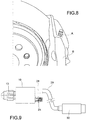
Figure 8 is a partial perspective view of a brake caliper; and -
Figure 9 is a schematic view of the adapter with a bleed screw and transducer mounted. - With reference initially to
figures 1 to 4 , an adapter, indicated collectively atnumber 10, comprises ahollow body 11 that forms aninternal cavity 12. Thehollow body 11 is made of rigid material, preferably of metallic material. For example, thehollow body 11 may be made of aluminum or aluminum alloys, which may withstand temperature peaks (800°C-1000°C) due to the proximity of the brake disc. - The
hollow body 11 forms a connectingappendage 13 penetrated by aninternal passage 14 that opens externally and is in fluid communication with theinternal cavity 12 of thehollow body 11. - The connecting
appendage 13 has acylindrical portion 15 with anexternal thread 16, which allows screwing into a corresponding threaded bleed seat A formed in the body B of a brake caliper (Figure 8 ), to which the adapter is to be mounted. The threaded bleed seat A of the brake caliper is the seat into which a traditional bleed screw may be screwed. During normal use of the vehicle, the bleed seat A is closed by a threaded plug (not shown). - The connecting
appendage 13 may have aconical end portion 17, as in the embodiment illustrated, corresponding to a traditional conical surface in the bleed seat A of the brake caliper. - The connecting
appendage 13 allows the adapter to be mounted in the bleed seat A of the brake caliper. In the installed condition, theinternal passage 14 allows the brake fluid from the body B of the brake caliper to be introduced into thecavity 12 of the adapter. - The
body 11 of the adapter forms at least two cylindrical seats with respective internal threads: a firstcylindrical seat 18 with aninternal thread 19 and a secondcylindrical seat 20 with aninternal thread 21. Bothseats internal cavity 12. - At least one of the
seats end connection surface cavity 12 and communicating therewith. - The
first seat 18 is configured to receive a bleed screw 24 (Figures 5 and 6 ) suitable to allow the removal of air and vapor bubbles from the brake fluid contained in thecavity 12 and originating from the hydraulic circuit that activates the brake caliper. - The
bleed screw 24 has a structure that does not differ significantly from a traditional bleed screw and has aconical end 25 coupled with or corresponding to the conicalend connection portion 20 of theseat 18. According to a configuration known per se, thebleed screw 24 may have alongitudinal channel 26 which opens at one end of the screw intended in use to be turned outwards, and atransverse channel 27 which opens near theconical end 25 and communicates with thelongitudinal channel 25. - The outer part of the
bleed screw 24 may be miniaturized for reasons of space so that it does not protrude appreciably from the adapter when mounted thereto. - The second threaded
seat 20 is configured to receive apressure transducer 28 with integrated temperature sensor to measure the temperature and pressure of the brake fluid introduced into thecavity 12. The integratedtransducer 28 is known in the art and does not need to be described in detail here. For example, an integrated transducer sold by Kulite Semiconductor Products, Inc. may be installed. - The
transducer 28 may be connected electrically, by means of acable 29, to aconnector 30 containing the electronics for power supply and management of the temperature and pressure sensors. Theconnector 30 is preferably fitted in the wheel arch of the motor vehicle, where the operating temperatures are lower than in the brake area. - When the
adapter 10 is mounted on the brake caliper, the connecting appendage is turned downwards and inserted into the bleed seat A, while the threadedseats - The
seats seat - The measurement and bleed operations may be carried out as follows. First of all, the external closure plug, which normally closes the circuit, is removed from the seat A of the brake caliper. Then the connecting
appendage 13 of the adapter is screwed into the seat A of the caliper. An integrated pressure-temperature transducer 28 is mounted in the first threadedseat 18 of the adapter. Ableed screw 24 is mounted in thesecond seat 20. Theconnector 30 is applied and connected electrically to an electronic control unit (not shown), conveniently located in a not excessively hot area of the vehicle to be tested, typically in the wheel arch. The air in the circuit is then removed by acting on thebleed screw 24, which is then closed. The test may then be carried out by measuring the temperature and the pressure of the brake fluid through thetransducer 28. After the measurements have been made, theconnector 30 is disconnected, and theadapter 10 is removed from the seat A of the brake caliper. A final bleed phase of the brake fluid is carried out; this bleed phase may be carried out by applying a traditional bleed screw in the seat A of the brake caliper, or thesame bleed screw 24 unscrewed from theadapter 10. - As may be appreciated, due to the configuration described above, the pressure and temperature of the brake fluid in a braking system may be measured without disconnecting the conduits of the hydraulic circuit. Experimental tests carried out by the Applicant have shown that the use of an adapter as described above allows an overall reduction in the preparation and testing time of approximately 50%. It will be appreciated that the risk of air being introduced into the braking system and trapped therein is eliminated. Possible complications linked, according to the traditional art, to disconnecting the hydraulic circuit at a height from which any air bubbles introduced into the circuit tended to go up towards the hydraulic control unit of the vehicle, are eliminated. The small size of the adapter allows it to be mounted on virtually any brake caliper, without problems of interference with mechanical members close to the brake caliper.
- According to one embodiment (
Figure 2 ), theinternal cavity 12 may be obtained as aninternal chamber 12 communicating on one side with theinternal passage 14 and communicating directly, on the other side, with the threadedseats - According to an alternative embodiment (
Figure 7 ), theinternal cavity 12 may be obtained in the form of a branched channel obtained within thebody 11 of the adapter. The channel may comprise twoconduits internal passage 14 and connect it respectively to the first 18 and thesecond seat 20. - According to a further alternative embodiment (not shown), the adapter may have two separate and distinct threaded seats instead of a single threaded seat for a single integrated temperature and pressure transducer. According to this variant, a first seat may be used to mount a pressure sensor and a second threaded seat may be used to mount a temperature sensor.
- Different aspects and embodiments of the adapter and the measurement method have been described. It is understood that each embodiment may be combined with any other embodiment. Moreover, without altering the principle of the invention, the embodiments and the details of construction may vary widely with respect to those described and illustrated purely by way of non-limiting example, without thereby departing from the scope of the invention as defined in the accompanying claims.
Claims (8)
- An adapter (10) for an integrated unit with a bleed valve, a temperature sensor and a pressure sensor for a brake caliper, the adapter comprising:- a hollow body (11), which forms an internal cavity (12);- a connecting appendage (13) having an external thread (16) and an internal passage (14) which opens on one end of the connecting appendage and is in fluid communication with the internal cavity (12);- at least a first seat (18) in fluid communication with the internal cavity (12) and having an internal thread (19) configured to receive at least one temperature and/or pressure transducer (28);- at least a second seat (20) in fluid communication with the internal cavity (12), wherein the second seat (20) has an internal thread (21) which is configured to receive a bleed screw (24), and a conical end connection surface (23) tapering towards and communicating with the internal cavity (12).
- An adapter according to claim 1, wherein the connecting appendage (13) has a cylindrical portion (15) providing the external thread (16), and a conical end portion (17).
- An adapter according to claim 1 or 2, wherein also the first seat (18) has a conical end connection surface (22) tapering towards and communicating with the internal cavity (12).
- An adapter according to claim 3, wherein the seats (18, 20) have a same shape and size.
- An adapter according to any one of the preceding claims, wherein the internal cavity (12) is shaped as a chamber (12) communicating on one side with the internal passage (14) and communicating directly, on the other side, with both threaded seats (18, 20).
- An adapter according to any one of claims 1 to 4, wherein the internal cavity (12) is shaped as a channel comprising two conduits (12a, 12b) which bifurcate from the internal passage (14) and connect the internal passage to the first seat (18) and the second seat (20), respectively.
- An adapter according to any one of the preceding claims, wherein the adapter has a further, third threaded seat, distinct and separate from the first and second threaded seats (18, 20), the third threaded seat being in fluid communication with the internal cavity (12) and having an internal thread configured to receive a temperature or pressure sensor.
- A method of measuring the temperature and pressure of the brake fluid in a braking system of a motor vehicle, the method comprising the steps of:providing an adapter (10) according to any one of the preceding claims,applying the adapter (10) to a brake caliper of a motor vehicle by screwing the threaded connecting appendage (13) into a threaded bleed seat (A) formed in the body (B) of the brake caliper,mounting an integrated pressure-temperature transducer (28) in the first threaded seat (18) of the adapter,mounting a bleed screw (24) in the second threaded seat (20),connecting electrically the transducer (28) to an electronic control unit of the motor vehicle, located in a remote position with respect to the brake caliper, by means of a connector (30) electrically connected to the transducer (28) through a cable (29),removing air and vapor from the brake fluid of the hydraulic circuit of the braking system by means of the bleed screw (24), and then closing the hydraulic circuit of the braking system by acting on the bleed screw (24),measuring the temperature and pressure of the brake fluid by means of the transducer (28),disconnecting the connector (30) from the electronic control unit of the vehicle,removing the adapter (10) from the bleed seat (A) of the brake caliper,performing a final bleed phase by mounting a bleed screw into the bleed seat (A), andclosing the bleed seat (A) by means of a threaded closure plug.
Applications Claiming Priority (1)
| Application Number | Priority Date | Filing Date | Title |
|---|---|---|---|
| IT102018000007883A IT201800007883A1 (en) | 2018-08-06 | 2018-08-06 | Adapter for an integrated unit with bleed valve, temperature sensor and pressure sensor for a brake caliper. |
Publications (2)
| Publication Number | Publication Date |
|---|---|
| EP3608183A1 true EP3608183A1 (en) | 2020-02-12 |
| EP3608183B1 EP3608183B1 (en) | 2021-03-24 |
Family
ID=63965921
Family Applications (1)
| Application Number | Title | Priority Date | Filing Date |
|---|---|---|---|
| EP19189833.7A Active EP3608183B1 (en) | 2018-08-06 | 2019-08-02 | An adapter for an integrated unit with a bleed valve, a temperature sensor and a pressure sensor for a brake caliper |
Country Status (3)
| Country | Link |
|---|---|
| EP (1) | EP3608183B1 (en) |
| ES (1) | ES2877634T3 (en) |
| IT (1) | IT201800007883A1 (en) |
Cited By (1)
| Publication number | Priority date | Publication date | Assignee | Title |
|---|---|---|---|---|
| US20230184303A1 (en) * | 2021-12-13 | 2023-06-15 | Jhih-Hua Zeng | Brake fluid pipe detector |
Citations (5)
| Publication number | Priority date | Publication date | Assignee | Title |
|---|---|---|---|---|
| US5964326A (en) * | 1998-03-17 | 1999-10-12 | Lee; Kin Bong | Apparatus for bleeding and refilling hydraulic brake system |
| WO2004011819A1 (en) * | 2002-07-30 | 2004-02-05 | Freni Brembo S.P.A. | Caliper for a disc brake |
| US20040074722A1 (en) * | 2002-09-11 | 2004-04-22 | Philippe Queval | Method for filling hydraulic apparatus with liquid, and apparatus thus filled |
| US20060192426A1 (en) * | 2002-08-14 | 2006-08-31 | Martin Baechle | Method for bleeding and refilling an electrohydraulic brake system |
| GB2457473A (en) * | 2008-02-14 | 2009-08-19 | Bifold Fluidpower Ltd | Isolation valve manifold |
-
2018
- 2018-08-06 IT IT102018000007883A patent/IT201800007883A1/en unknown
-
2019
- 2019-08-02 EP EP19189833.7A patent/EP3608183B1/en active Active
- 2019-08-02 ES ES19189833T patent/ES2877634T3/en active Active
Patent Citations (5)
| Publication number | Priority date | Publication date | Assignee | Title |
|---|---|---|---|---|
| US5964326A (en) * | 1998-03-17 | 1999-10-12 | Lee; Kin Bong | Apparatus for bleeding and refilling hydraulic brake system |
| WO2004011819A1 (en) * | 2002-07-30 | 2004-02-05 | Freni Brembo S.P.A. | Caliper for a disc brake |
| US20060192426A1 (en) * | 2002-08-14 | 2006-08-31 | Martin Baechle | Method for bleeding and refilling an electrohydraulic brake system |
| US20040074722A1 (en) * | 2002-09-11 | 2004-04-22 | Philippe Queval | Method for filling hydraulic apparatus with liquid, and apparatus thus filled |
| GB2457473A (en) * | 2008-02-14 | 2009-08-19 | Bifold Fluidpower Ltd | Isolation valve manifold |
Cited By (2)
| Publication number | Priority date | Publication date | Assignee | Title |
|---|---|---|---|---|
| US20230184303A1 (en) * | 2021-12-13 | 2023-06-15 | Jhih-Hua Zeng | Brake fluid pipe detector |
| US12253128B2 (en) * | 2021-12-13 | 2025-03-18 | Jhih-Hua Zeng | Brake fluid pipe detector |
Also Published As
| Publication number | Publication date |
|---|---|
| ES2877634T3 (en) | 2021-11-17 |
| EP3608183B1 (en) | 2021-03-24 |
| IT201800007883A1 (en) | 2020-02-06 |
Similar Documents
| Publication | Publication Date | Title |
|---|---|---|
| US10981621B2 (en) | Hydraulic line connection for a hydraulic brake for handlebar steering and handlebar with hydraulic brake | |
| JP4787222B2 (en) | Brake system | |
| CN106458179B (en) | Hydraulic block for hydraulic assembly of anti-skid adjustment system for vehicle hydraulic braking equipment | |
| EP3608183B1 (en) | An adapter for an integrated unit with a bleed valve, a temperature sensor and a pressure sensor for a brake caliper | |
| CN109844350B (en) | Pneumatic Disc Brakes | |
| US4566805A (en) | Device for determining and checking condition state and other parameters of a pressure fluid | |
| CN104596907A (en) | Measurement method for large-displacement shear-flow of rock under high temperature and high pressure | |
| CN206420616U (en) | A kind of pressure sensor off-line calibration device | |
| CN207019834U (en) | Antifreezing joint for pressure gauge and its antifreeze detection means of fluid pressure | |
| EP3984787B1 (en) | Multifunctional external inflating valve and mounting method for loading device of inflating valve | |
| CN101706328A (en) | Thermocouple lead sealing equipment | |
| JP5686908B2 (en) | Method for inspecting circuit separation of double gear pump | |
| CN110375893B (en) | Double-layer piston type pulling and pressing dual-purpose tension meter | |
| US2664101A (en) | Automatic shutoff valve for pressure fluid systems | |
| CN104007247B (en) | Tunnel tunnel face confining pressure and extrusion deformation relation test unit and test method | |
| CN106352997B (en) | A device for measuring oil temperature of cylinder block | |
| WO2020147811A1 (en) | Integrity detection system and method for freeze dryer filter | |
| EP0978712A1 (en) | Temperature sensor holding means | |
| US1200432A (en) | Fitting for pressure-gages. | |
| CN108020468B (en) | Pressure-resistant test platform for automobile brake rubber pipe | |
| JP4973883B2 (en) | Cylinder pressure measurement parts | |
| CN107345609A (en) | A kind of axial pressing type fast assembling-disassembling sealing detection piecing devices | |
| EP4378772B1 (en) | Brake system component for a vehicle, testing system for assessing a quality parameter of a brake fluid, test device, vehicle, and method for assessing a quality parameter of a brake fluid | |
| KR102507265B1 (en) | Brake pad mounting omission checker and brake pad omission inspection method using the same | |
| JP5912460B2 (en) | Residual air amount measuring method and measuring jig |
Legal Events
| Date | Code | Title | Description |
|---|---|---|---|
| PUAI | Public reference made under article 153(3) epc to a published international application that has entered the european phase |
Free format text: ORIGINAL CODE: 0009012 |
|
| STAA | Information on the status of an ep patent application or granted ep patent |
Free format text: STATUS: THE APPLICATION HAS BEEN PUBLISHED |
|
| AK | Designated contracting states |
Kind code of ref document: A1 Designated state(s): AL AT BE BG CH CY CZ DE DK EE ES FI FR GB GR HR HU IE IS IT LI LT LU LV MC MK MT NL NO PL PT RO RS SE SI SK SM TR |
|
| AX | Request for extension of the european patent |
Extension state: BA ME |
|
| STAA | Information on the status of an ep patent application or granted ep patent |
Free format text: STATUS: REQUEST FOR EXAMINATION WAS MADE |
|
| 17P | Request for examination filed |
Effective date: 20200805 |
|
| RBV | Designated contracting states (corrected) |
Designated state(s): AL AT BE BG CH CY CZ DE DK EE ES FI FR GB GR HR HU IE IS IT LI LT LU LV MC MK MT NL NO PL PT RO RS SE SI SK SM TR |
|
| GRAP | Despatch of communication of intention to grant a patent |
Free format text: ORIGINAL CODE: EPIDOSNIGR1 |
|
| STAA | Information on the status of an ep patent application or granted ep patent |
Free format text: STATUS: GRANT OF PATENT IS INTENDED |
|
| INTG | Intention to grant announced |
Effective date: 20201008 |
|
| GRAS | Grant fee paid |
Free format text: ORIGINAL CODE: EPIDOSNIGR3 |
|
| GRAA | (expected) grant |
Free format text: ORIGINAL CODE: 0009210 |
|
| STAA | Information on the status of an ep patent application or granted ep patent |
Free format text: STATUS: THE PATENT HAS BEEN GRANTED |
|
| AK | Designated contracting states |
Kind code of ref document: B1 Designated state(s): AL AT BE BG CH CY CZ DE DK EE ES FI FR GB GR HR HU IE IS IT LI LT LU LV MC MK MT NL NO PL PT RO RS SE SI SK SM TR |
|
| REG | Reference to a national code |
Ref country code: GB Ref legal event code: FG4D |
|
| REG | Reference to a national code |
Ref country code: CH Ref legal event code: EP |
|
| REG | Reference to a national code |
Ref country code: IE Ref legal event code: FG4D |
|
| REG | Reference to a national code |
Ref country code: DE Ref legal event code: R096 Ref document number: 602019003395 Country of ref document: DE Ref country code: AT Ref legal event code: REF Ref document number: 1374188 Country of ref document: AT Kind code of ref document: T Effective date: 20210415 |
|
| REG | Reference to a national code |
Ref country code: LT Ref legal event code: MG9D |
|
| PG25 | Lapsed in a contracting state [announced via postgrant information from national office to epo] |
Ref country code: NO Free format text: LAPSE BECAUSE OF FAILURE TO SUBMIT A TRANSLATION OF THE DESCRIPTION OR TO PAY THE FEE WITHIN THE PRESCRIBED TIME-LIMIT Effective date: 20210624 Ref country code: FI Free format text: LAPSE BECAUSE OF FAILURE TO SUBMIT A TRANSLATION OF THE DESCRIPTION OR TO PAY THE FEE WITHIN THE PRESCRIBED TIME-LIMIT Effective date: 20210324 Ref country code: GR Free format text: LAPSE BECAUSE OF FAILURE TO SUBMIT A TRANSLATION OF THE DESCRIPTION OR TO PAY THE FEE WITHIN THE PRESCRIBED TIME-LIMIT Effective date: 20210625 Ref country code: BG Free format text: LAPSE BECAUSE OF FAILURE TO SUBMIT A TRANSLATION OF THE DESCRIPTION OR TO PAY THE FEE WITHIN THE PRESCRIBED TIME-LIMIT Effective date: 20210624 Ref country code: HR Free format text: LAPSE BECAUSE OF FAILURE TO SUBMIT A TRANSLATION OF THE DESCRIPTION OR TO PAY THE FEE WITHIN THE PRESCRIBED TIME-LIMIT Effective date: 20210324 |
|
| PG25 | Lapsed in a contracting state [announced via postgrant information from national office to epo] |
Ref country code: SE Free format text: LAPSE BECAUSE OF FAILURE TO SUBMIT A TRANSLATION OF THE DESCRIPTION OR TO PAY THE FEE WITHIN THE PRESCRIBED TIME-LIMIT Effective date: 20210324 Ref country code: RS Free format text: LAPSE BECAUSE OF FAILURE TO SUBMIT A TRANSLATION OF THE DESCRIPTION OR TO PAY THE FEE WITHIN THE PRESCRIBED TIME-LIMIT Effective date: 20210324 Ref country code: LV Free format text: LAPSE BECAUSE OF FAILURE TO SUBMIT A TRANSLATION OF THE DESCRIPTION OR TO PAY THE FEE WITHIN THE PRESCRIBED TIME-LIMIT Effective date: 20210324 |
|
| REG | Reference to a national code |
Ref country code: NL Ref legal event code: MP Effective date: 20210324 |
|
| REG | Reference to a national code |
Ref country code: AT Ref legal event code: MK05 Ref document number: 1374188 Country of ref document: AT Kind code of ref document: T Effective date: 20210324 |
|
| PG25 | Lapsed in a contracting state [announced via postgrant information from national office to epo] |
Ref country code: NL Free format text: LAPSE BECAUSE OF FAILURE TO SUBMIT A TRANSLATION OF THE DESCRIPTION OR TO PAY THE FEE WITHIN THE PRESCRIBED TIME-LIMIT Effective date: 20210324 |
|
| PG25 | Lapsed in a contracting state [announced via postgrant information from national office to epo] |
Ref country code: SM Free format text: LAPSE BECAUSE OF FAILURE TO SUBMIT A TRANSLATION OF THE DESCRIPTION OR TO PAY THE FEE WITHIN THE PRESCRIBED TIME-LIMIT Effective date: 20210324 Ref country code: AT Free format text: LAPSE BECAUSE OF FAILURE TO SUBMIT A TRANSLATION OF THE DESCRIPTION OR TO PAY THE FEE WITHIN THE PRESCRIBED TIME-LIMIT Effective date: 20210324 Ref country code: EE Free format text: LAPSE BECAUSE OF FAILURE TO SUBMIT A TRANSLATION OF THE DESCRIPTION OR TO PAY THE FEE WITHIN THE PRESCRIBED TIME-LIMIT Effective date: 20210324 Ref country code: CZ Free format text: LAPSE BECAUSE OF FAILURE TO SUBMIT A TRANSLATION OF THE DESCRIPTION OR TO PAY THE FEE WITHIN THE PRESCRIBED TIME-LIMIT Effective date: 20210324 Ref country code: LT Free format text: LAPSE BECAUSE OF FAILURE TO SUBMIT A TRANSLATION OF THE DESCRIPTION OR TO PAY THE FEE WITHIN THE PRESCRIBED TIME-LIMIT Effective date: 20210324 |
|
| REG | Reference to a national code |
Ref country code: ES Ref legal event code: FG2A Ref document number: 2877634 Country of ref document: ES Kind code of ref document: T3 Effective date: 20211117 |
|
| PG25 | Lapsed in a contracting state [announced via postgrant information from national office to epo] |
Ref country code: IS Free format text: LAPSE BECAUSE OF FAILURE TO SUBMIT A TRANSLATION OF THE DESCRIPTION OR TO PAY THE FEE WITHIN THE PRESCRIBED TIME-LIMIT Effective date: 20210724 Ref country code: PL Free format text: LAPSE BECAUSE OF FAILURE TO SUBMIT A TRANSLATION OF THE DESCRIPTION OR TO PAY THE FEE WITHIN THE PRESCRIBED TIME-LIMIT Effective date: 20210324 Ref country code: SK Free format text: LAPSE BECAUSE OF FAILURE TO SUBMIT A TRANSLATION OF THE DESCRIPTION OR TO PAY THE FEE WITHIN THE PRESCRIBED TIME-LIMIT Effective date: 20210324 Ref country code: RO Free format text: LAPSE BECAUSE OF FAILURE TO SUBMIT A TRANSLATION OF THE DESCRIPTION OR TO PAY THE FEE WITHIN THE PRESCRIBED TIME-LIMIT Effective date: 20210324 Ref country code: PT Free format text: LAPSE BECAUSE OF FAILURE TO SUBMIT A TRANSLATION OF THE DESCRIPTION OR TO PAY THE FEE WITHIN THE PRESCRIBED TIME-LIMIT Effective date: 20210726 |
|
| REG | Reference to a national code |
Ref country code: DE Ref legal event code: R097 Ref document number: 602019003395 Country of ref document: DE |
|
| PG25 | Lapsed in a contracting state [announced via postgrant information from national office to epo] |
Ref country code: AL Free format text: LAPSE BECAUSE OF FAILURE TO SUBMIT A TRANSLATION OF THE DESCRIPTION OR TO PAY THE FEE WITHIN THE PRESCRIBED TIME-LIMIT Effective date: 20210324 Ref country code: DK Free format text: LAPSE BECAUSE OF FAILURE TO SUBMIT A TRANSLATION OF THE DESCRIPTION OR TO PAY THE FEE WITHIN THE PRESCRIBED TIME-LIMIT Effective date: 20210324 |
|
| PLBE | No opposition filed within time limit |
Free format text: ORIGINAL CODE: 0009261 |
|
| STAA | Information on the status of an ep patent application or granted ep patent |
Free format text: STATUS: NO OPPOSITION FILED WITHIN TIME LIMIT |
|
| PG25 | Lapsed in a contracting state [announced via postgrant information from national office to epo] |
Ref country code: SI Free format text: LAPSE BECAUSE OF FAILURE TO SUBMIT A TRANSLATION OF THE DESCRIPTION OR TO PAY THE FEE WITHIN THE PRESCRIBED TIME-LIMIT Effective date: 20210324 |
|
| 26N | No opposition filed |
Effective date: 20220104 |
|
| PG25 | Lapsed in a contracting state [announced via postgrant information from national office to epo] |
Ref country code: MC Free format text: LAPSE BECAUSE OF FAILURE TO SUBMIT A TRANSLATION OF THE DESCRIPTION OR TO PAY THE FEE WITHIN THE PRESCRIBED TIME-LIMIT Effective date: 20210324 |
|
| REG | Reference to a national code |
Ref country code: BE Ref legal event code: MM Effective date: 20210831 |
|
| PG25 | Lapsed in a contracting state [announced via postgrant information from national office to epo] |
Ref country code: IS Free format text: LAPSE BECAUSE OF FAILURE TO SUBMIT A TRANSLATION OF THE DESCRIPTION OR TO PAY THE FEE WITHIN THE PRESCRIBED TIME-LIMIT Effective date: 20210724 Ref country code: LU Free format text: LAPSE BECAUSE OF NON-PAYMENT OF DUE FEES Effective date: 20210802 |
|
| PG25 | Lapsed in a contracting state [announced via postgrant information from national office to epo] |
Ref country code: IE Free format text: LAPSE BECAUSE OF NON-PAYMENT OF DUE FEES Effective date: 20210802 Ref country code: BE Free format text: LAPSE BECAUSE OF NON-PAYMENT OF DUE FEES Effective date: 20210831 |
|
| REG | Reference to a national code |
Ref country code: CH Ref legal event code: PL |
|
| PG25 | Lapsed in a contracting state [announced via postgrant information from national office to epo] |
Ref country code: LI Free format text: LAPSE BECAUSE OF NON-PAYMENT OF DUE FEES Effective date: 20220831 Ref country code: CH Free format text: LAPSE BECAUSE OF NON-PAYMENT OF DUE FEES Effective date: 20220831 |
|
| PG25 | Lapsed in a contracting state [announced via postgrant information from national office to epo] |
Ref country code: CY Free format text: LAPSE BECAUSE OF FAILURE TO SUBMIT A TRANSLATION OF THE DESCRIPTION OR TO PAY THE FEE WITHIN THE PRESCRIBED TIME-LIMIT Effective date: 20210324 |
|
| PG25 | Lapsed in a contracting state [announced via postgrant information from national office to epo] |
Ref country code: HU Free format text: LAPSE BECAUSE OF FAILURE TO SUBMIT A TRANSLATION OF THE DESCRIPTION OR TO PAY THE FEE WITHIN THE PRESCRIBED TIME-LIMIT; INVALID AB INITIO Effective date: 20190802 |
|
| PG25 | Lapsed in a contracting state [announced via postgrant information from national office to epo] |
Ref country code: MK Free format text: LAPSE BECAUSE OF FAILURE TO SUBMIT A TRANSLATION OF THE DESCRIPTION OR TO PAY THE FEE WITHIN THE PRESCRIBED TIME-LIMIT Effective date: 20210324 |
|
| PG25 | Lapsed in a contracting state [announced via postgrant information from national office to epo] |
Ref country code: TR Free format text: LAPSE BECAUSE OF FAILURE TO SUBMIT A TRANSLATION OF THE DESCRIPTION OR TO PAY THE FEE WITHIN THE PRESCRIBED TIME-LIMIT Effective date: 20210324 |
|
| PG25 | Lapsed in a contracting state [announced via postgrant information from national office to epo] |
Ref country code: MT Free format text: LAPSE BECAUSE OF FAILURE TO SUBMIT A TRANSLATION OF THE DESCRIPTION OR TO PAY THE FEE WITHIN THE PRESCRIBED TIME-LIMIT Effective date: 20210324 |
|
| PGFP | Annual fee paid to national office [announced via postgrant information from national office to epo] |
Ref country code: ES Payment date: 20250901 Year of fee payment: 7 |
|
| PGFP | Annual fee paid to national office [announced via postgrant information from national office to epo] |
Ref country code: DE Payment date: 20250822 Year of fee payment: 7 |
|
| PGFP | Annual fee paid to national office [announced via postgrant information from national office to epo] |
Ref country code: IT Payment date: 20250609 Year of fee payment: 7 |
|
| PGFP | Annual fee paid to national office [announced via postgrant information from national office to epo] |
Ref country code: GB Payment date: 20250820 Year of fee payment: 7 |
|
| PGFP | Annual fee paid to national office [announced via postgrant information from national office to epo] |
Ref country code: FR Payment date: 20250730 Year of fee payment: 7 |