EP3608135A1 - Open roof construction for a vehicle and method of attaching a panel - Google Patents
Open roof construction for a vehicle and method of attaching a panel Download PDFInfo
- Publication number
- EP3608135A1 EP3608135A1 EP18188278.8A EP18188278A EP3608135A1 EP 3608135 A1 EP3608135 A1 EP 3608135A1 EP 18188278 A EP18188278 A EP 18188278A EP 3608135 A1 EP3608135 A1 EP 3608135A1
- Authority
- EP
- European Patent Office
- Prior art keywords
- panel
- opening
- screw
- holes
- funnel
- Prior art date
- Legal status (The legal status is an assumption and is not a legal conclusion. Google has not performed a legal analysis and makes no representation as to the accuracy of the status listed.)
- Granted
Links
- 238000010276 construction Methods 0.000 title claims abstract description 30
- 238000000034 method Methods 0.000 title claims description 6
- 230000007246 mechanism Effects 0.000 claims abstract description 19
- 238000004804 winding Methods 0.000 description 3
- 230000002349 favourable effect Effects 0.000 description 1
- 239000011521 glass Substances 0.000 description 1
- 238000004519 manufacturing process Methods 0.000 description 1
- 230000002787 reinforcement Effects 0.000 description 1
- 230000000284 resting effect Effects 0.000 description 1
- 230000000475 sunscreen effect Effects 0.000 description 1
- 239000000516 sunscreening agent Substances 0.000 description 1
Images


Classifications
-
- B—PERFORMING OPERATIONS; TRANSPORTING
- B60—VEHICLES IN GENERAL
- B60J—WINDOWS, WINDSCREENS, NON-FIXED ROOFS, DOORS, OR SIMILAR DEVICES FOR VEHICLES; REMOVABLE EXTERNAL PROTECTIVE COVERINGS SPECIALLY ADAPTED FOR VEHICLES
- B60J7/00—Non-fixed roofs; Roofs with movable panels, e.g. rotary sunroofs
- B60J7/02—Non-fixed roofs; Roofs with movable panels, e.g. rotary sunroofs of sliding type, e.g. comprising guide shoes
- B60J7/022—Sliding roof trays or assemblies
-
- B—PERFORMING OPERATIONS; TRANSPORTING
- B60—VEHICLES IN GENERAL
- B60J—WINDOWS, WINDSCREENS, NON-FIXED ROOFS, DOORS, OR SIMILAR DEVICES FOR VEHICLES; REMOVABLE EXTERNAL PROTECTIVE COVERINGS SPECIALLY ADAPTED FOR VEHICLES
- B60J7/00—Non-fixed roofs; Roofs with movable panels, e.g. rotary sunroofs
- B60J7/02—Non-fixed roofs; Roofs with movable panels, e.g. rotary sunroofs of sliding type, e.g. comprising guide shoes
- B60J7/04—Non-fixed roofs; Roofs with movable panels, e.g. rotary sunroofs of sliding type, e.g. comprising guide shoes with rigid plate-like element or elements, e.g. open roofs with harmonica-type folding rigid panels
- B60J7/043—Sunroofs e.g. sliding above the roof
-
- B—PERFORMING OPERATIONS; TRANSPORTING
- B60—VEHICLES IN GENERAL
- B60J—WINDOWS, WINDSCREENS, NON-FIXED ROOFS, DOORS, OR SIMILAR DEVICES FOR VEHICLES; REMOVABLE EXTERNAL PROTECTIVE COVERINGS SPECIALLY ADAPTED FOR VEHICLES
- B60J7/00—Non-fixed roofs; Roofs with movable panels, e.g. rotary sunroofs
- B60J7/0007—Non-fixed roofs; Roofs with movable panels, e.g. rotary sunroofs moveable head-liners, screens, curtains or blinds for ceilings
- B60J7/0023—Non-fixed roofs; Roofs with movable panels, e.g. rotary sunroofs moveable head-liners, screens, curtains or blinds for ceilings flexible and foldable
-
- B—PERFORMING OPERATIONS; TRANSPORTING
- B60—VEHICLES IN GENERAL
- B60J—WINDOWS, WINDSCREENS, NON-FIXED ROOFS, DOORS, OR SIMILAR DEVICES FOR VEHICLES; REMOVABLE EXTERNAL PROTECTIVE COVERINGS SPECIALLY ADAPTED FOR VEHICLES
- B60J7/00—Non-fixed roofs; Roofs with movable panels, e.g. rotary sunroofs
- B60J7/02—Non-fixed roofs; Roofs with movable panels, e.g. rotary sunroofs of sliding type, e.g. comprising guide shoes
- B60J7/04—Non-fixed roofs; Roofs with movable panels, e.g. rotary sunroofs of sliding type, e.g. comprising guide shoes with rigid plate-like element or elements, e.g. open roofs with harmonica-type folding rigid panels
- B60J7/057—Driving or actuating arrangements e.g. manually operated levers or knobs
- B60J7/0573—Driving or actuating arrangements e.g. manually operated levers or knobs power driven arrangements, e.g. electrical
Definitions
- the invention firstly relates to an open roof construction for a vehicle according to the preamble of claim 1.
- At least one pair of holes is provided with a funnel which is in line with this pair of holes at least when the panel is in its closed position in order to guide a screw driver to the respective screw which is pre-mounted in or in front of the pair of holes.
- At least one pair of holes is in a position before or behind the passage opening when the panel is in its closed position within the roof opening, and wherein the frame is provided with a mounting opening in a longitudinal position which is transversely in line with said at least one pair of holes and which is dimensioned to allow passage of a screw driver to fasten the screw of said at least one pair of holes.
- Such mounting opening allows attachment of the panel to the operating mechanism in the closed position of the panel which has the advantage that attachment and height adjustment of the panel can be done in one operation.
- such mounting opening may not provide a proper view of the screw head, so that the funnel facilitates engagement with the screw head.
- such mounting opening may also be useful without the use of a funnel.
- the at least one funnel is attached, for example clipped, to a guide rail for the operating mechanism, which extends at least along the passage opening in the frame in longitudinal direction of the vehicle.
- the funnel is used for a screw near the front of the panel it may be provided in a wind deflector which is in a lower rest position when the panel is in the closed position.
- the funnel is used for the screw near the rear of the panel it may be provided on or be part of a rear beam of the frame.
- the funnel has an entrance opening where the screwdriver is inserted and an exit opening opposite the pair of holes, and it is favorable if the entrance opening cross-section is at least twice that of the exit opening to still guide the screw driver bit to the screw head even if there is a big misalignment.
- the funnel may be adapted to accommodate and hold a head of the screw in position in front of the pair of holes, or the funnel may even be adapted to accommodate and hold the head of the screw and a washer associated with the screw.
- the exit opening will generally have a circular cross-section, but the entrance opening may have a cross section different from a circle, such as rectangular or oval.
- Such different cross section may be chosen if circumstances require it, for example due to dimensional constraints, because a small vertical package of the open roof construction is very important.
- the funnel may even be open at the top, but may then be delimited in the closed position of the panel by another part of the open roof construction, such as the panel or a part attached to it, and wherein preferably the inner cross section of the open top funnel is more than 60% of a complete cross section.
- the invention also includes a method of attaching a panel to an operating mechanism of an open roof construction, comprising the steps of: providing a frame having a passage opening therein, providing an operating mechanism at each longitudinal side of the passage opening, said operating mechanism including a movable panel support, providing a panel having on each longitudinal side a panel bracket for attachment to the corresponding panel support by means of a screw fitting in a corresponding holes in the panel bracket and panel support, respectively, the longitudinal dimension of the panel being larger than that of the passage opening, and at least one of the holes being positioned before or behind the passage opening when the panel is in its closed position, providing the frame with a mounting opening in a position in the same transverse plane as the corresponding holes in the panel bracket and support when the panel is in its closed position, and bringing a screw driver through said opening in line with the screw which is pre-mounted in or in front of the holes and fastening the screw.
- the screw driver is brought in line with the screw by means of a funnel mounted in line with the corresponding holes so as to guide the screw driver to the screw.
- the screw may be pre-mounted in the holes, but it is also possible to pre-mount the screw and optionally a washer in the funnel.
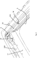
- FIG. 1 an example is illustrated of an open roof construction for a vehicle, such as a passenger car.
- Said open roof construction is for opening and closing at least one roof opening 1 in a fixed roof part 2 of the vehicle and includes at least one movable panel, in particular a rigid, transparent panel 3 which, by an operating mechanism 4 not illustrated in detail but known per se, can be moved for opening and closing said roof opening 1.
- movable panel 3 is guided in longitudinal guide rails 5 mounted to or formed in stationary roof part 2 along longitudinal sides of roof opening 1.
- a user operated device such as a motor or crank (not illustrated) is operably coupled to panel 3 via cables or the like to move panel 3 selectively between its open and closed positions.
- closure panel 3 has been illustrated in a position in which it closes roof opening 1.
- the invention can be used for all types of open roof constructions comprising one or more panels.
- the panel 3 comprises a panel main body 6, in particular made of glass or plastic to reduce the weight of panel 3.
- the panel 3 further comprises a panel bracket 7, which is for example attached to or is part of a reinforcement mounted to the bottom side of panel main body 6.
- the operating mechanism 4 includes a movable panel support 8 on its upper side to allow attachment of panel bracket 7 and therewith movement of panel 3 between the closed and open positions.
- the guide rails 5 for the operating mechanism 4 are provided on both longitudinal sides (i.e. running in longitudinal direction of the vehicle) of a passage opening 9 in a frame 10 acting as stationary part of the open roof construction and being adapted to be attached to fixed roof part 2 of the vehicle.
- the passage opening 9 is smaller in size than roof opening 1 both at the front and rear of roof opening 1 where a wind deflector 11 and a rollo winding tube 12 of a rollo sunscreen system are arranged, respectively, and at the longitudinal sides where guide rails 5 are mounted on frame 10 at a position bordering passage opening 9, but at least partially below roof opening 1.
- the guide rails 5 are mounted on side beams 10A, 10B of frame 10, wind deflector 11 on a front beam 10C and rollo winding tube 12 on a rear beam 10D of frame 10.
- the panel supports are provided with a number of holes 13 and panel brackets 7 with the same number of threaded holes 14, such that a screw 15 can be inserted into aligned holes 13 and 14 and tightened to clamp panel supports 8 to the respective panel brackets 7.
- a washer 16 may be used in each screwed connection.
- a funnel 18 is arranged for each pair of holes 13, 14.
- the funnel 18 is aligned with holes 13, 14 at least when panel 3 is in its closed position within roof opening 1. If funnels 18 would be mounted to panel 3, then they would always be aligned with holes 13, 14, but if funnels 18 are mounted to a part of frame 10, they are positioned such that they are only aligned with the corresponding holes 13, 14 when panel 3 is closed.
- the screws 15 are preferably tightened in the closed position of panel 3, because panel 3 is preferably adjusted to the correct height with respect to fixed roof part 2, i.e. flush with the surrounding fixed roof part, when it is in closed position, so in this way adjustment and following final attachment of panel bracket 7 to panel support 8 can be done in one sequence without having to move panel 3.
- rear cross beam 10D of frame 10 is provided with a mounting opening 19 at a longitudinal position which is in the same transverse plane as the rear pair of holes 13, 14.
- Mounting opening 19 is also positioned at an appropriate distance from panel support 8 and thus from the head of screw 15 in order to engage screw driver S with screw 15, and is dimensioned to allow passage of the screw driver head and bit.
- funnel 18 for the rear pair of holes 13, 14 is mounted on a support member 24 which is part of or arranged on rear beam 10D such that funnel 18 is aligned with rear pair of holes 13, 14 when panel 3 is in its closed position.
- Figs. 4 and 6 show that funnels 19 for the central portion of panel 3 are clipped on a flange 20 of guide rail 15. If the level of the upper side of flange 20 is above the opening in funnel 18, flange 20 will have a passage opening 21 for screw driver 17. The opening 21 could also be used to clip funnel 18 to flange 20.
- FIG. 7 shows funnel 18 at the front pair of holes 13 and 14.
- Front beam has a mounting opening (not shown) in front beam 10C and funnel 18 is provided in a side arm 11A of wind deflector 11. Wind deflector 11 will be in a low resting position below fixed roof part 2 when panel 3 is in its closed position.
- Fig. 8 shows a very schematic illustration of a funnel 18.
- Funnel 18 has an entrance 22 where screw driver S enters funnel 18 and an exit 23 opposite to holes 13, 14.
- Exit 23 has a cross section or diameter D1 which is large enough to allow passage of the screw driver bit and small enough to ensure that the screw driver bit is brought in engagement with screw 15.
- Entrance 22 is larger than exit 23 so that funnel 18 is formed where the screw driver bit is easily caught by entrance 22 and then guided by a narrowing passage 25 through funnel 18 to small exit 23 where the screw driver bit will be aligned with holes 13, 14 and screw 15.
- Diameter D2 (or smallest dimension of entrance 22) is preferably 2 times or more larger than exit diameter D1. Diameter D2 will be limited by the available space.
- Fig. 9 shows 3 embodiments of funnel 18 of which the entrance has a cross section that is either circular ( Fig. 9A ) or has a shape diverging from a circle.
- the entrance 22 has an oval cross section
- entrance 22 of Fig. 9C is rectangular, in particular square.
- Figs. 9B and 9C show larger entrances than Fig. 9A , but the height is not or hardly greater.
- Fig. 10 shows a funnel 18 which has an open top, at least in the first part of funnel 18 from entrance 22. This reduces the height of funnel 18, while in the closed position of panel 3, the bottom side of panel main body 6 (or a part attached to it) will be close to the top side of funnel 18 so that it will act as a part of funnel 18.
- funnel 18 is adapted to accommodate and hold screw 15 and washer 16 in a position to be engaged by screw driver S and to be pushed out by it so that the screw thread thereof will be inserted through hole 13 in panel bracket 7 and into threaded hole 14 of panel support 8. In this way, it is not necessary to pre-mount screw 15 into holes 13, 14 in an open position of panel 3 before screw 15 is brought into alignment with the respective funnel 18 when panel 3 is moved to its closed position.
- the passage in funnel 18 smaller at the entrance side of screw 15 to even better guide screw driver S to screw 15 and provide a limiting wall for the head of screw 15.
- hole 13 in panel bracket 7 is (much) larger than the shaft of screw 15 so that panel bracket 7 can be adjusted with respect to panel support 8 to obtain a correct position of panel 3 when it is closed.
- the invention is not limited to the embodiments described before, which may be varied widely within the scope of the invention as defined by the appending claims.
- the funnels also in other positions, for example in front of a screw for adjusting the wind deflector or other parts that are finally fastened with the open roof construction already mounted in the vehicle and difficult to reach or see.
- the mounting opening in the frame for the screw driver may be a hole separate from the passage opening, for example if it is made behind the rollo screen winding tube, but it may also connect to the passage opening, for example formed as a bulge or recess to the mainly rectangular passage opening.
Abstract
Description
- The invention firstly relates to an open roof construction for a vehicle according to the preamble of
claim 1. - These types of open roof constructions are still manufactured partly by human manipulations. The screws for attaching the panel to the operating mechanism are tightened by a screw driver handled by an operator.
- It is one of the objects of the present invention to improve the open roof construction so as to facilitate manufacture thereof.
- To obtain these and other objects, at least one pair of holes is provided with a funnel which is in line with this pair of holes at least when the panel is in its closed position in order to guide a screw driver to the respective screw which is pre-mounted in or in front of the pair of holes.
- In this way, it is much easier to bring a bit of the screw driver in engagement with the screw head, in particular if the operator has no or a bad view on the screw head.
- For example, if at least one pair of holes is in a position before or behind the passage opening when the panel is in its closed position within the roof opening, and wherein the frame is provided with a mounting opening in a longitudinal position which is transversely in line with said at least one pair of holes and which is dimensioned to allow passage of a screw driver to fasten the screw of said at least one pair of holes.
- Such mounting opening allows attachment of the panel to the operating mechanism in the closed position of the panel which has the advantage that attachment and height adjustment of the panel can be done in one operation. However, such mounting opening may not provide a proper view of the screw head, so that the funnel facilitates engagement with the screw head. However, such mounting opening may also be useful without the use of a funnel.
- In one embodiment, the at least one funnel is attached, for example clipped, to a guide rail for the operating mechanism, which extends at least along the passage opening in the frame in longitudinal direction of the vehicle.
- If the funnel is used for a screw near the front of the panel it may be provided in a wind deflector which is in a lower rest position when the panel is in the closed position.
- If the funnel is used for the screw near the rear of the panel it may be provided on or be part of a rear beam of the frame.
- The funnel has an entrance opening where the screwdriver is inserted and an exit opening opposite the pair of holes, and it is favorable if the entrance opening cross-section is at least twice that of the exit opening to still guide the screw driver bit to the screw head even if there is a big misalignment.
- The funnel may be adapted to accommodate and hold a head of the screw in position in front of the pair of holes, or the funnel may even be adapted to accommodate and hold the head of the screw and a washer associated with the screw.
- In this way it is not necessary to pre-mount the screw in the pair of holes, for example if the panel is in the open position and then move the panel to the closed position to perform the final mounting operation. The funnel will be attached to the open roof construction with the screw and washer already in place.
- The exit opening will generally have a circular cross-section, but the entrance opening may have a cross section different from a circle, such as rectangular or oval.
- Such different cross section may be chosen if circumstances require it, for example due to dimensional constraints, because a small vertical package of the open roof construction is very important.
- The funnel may even be open at the top, but may then be delimited in the closed position of the panel by another part of the open roof construction, such as the panel or a part attached to it, and wherein preferably the inner cross section of the open top funnel is more than 60% of a complete cross section.
- This will still allow for a reliable guidance of the screw driver bit to the screw head.
- The invention also includes a method of attaching a panel to an operating mechanism of an open roof construction, comprising the steps of: providing a frame having a passage opening therein, providing an operating mechanism at each longitudinal side of the passage opening, said operating mechanism including a movable panel support, providing a panel having on each longitudinal side a panel bracket for attachment to the corresponding panel support by means of a screw fitting in a corresponding holes in the panel bracket and panel support, respectively, the longitudinal dimension of the panel being larger than that of the passage opening, and at least one of the holes being positioned before or behind the passage opening when the panel is in its closed position, providing the frame with a mounting opening in a position in the same transverse plane as the corresponding holes in the panel bracket and support when the panel is in its closed position, and bringing a screw driver through said opening in line with the screw which is pre-mounted in or in front of the holes and fastening the screw.
- Preferably, the screw driver is brought in line with the screw by means of a funnel mounted in line with the corresponding holes so as to guide the screw driver to the screw.
- The screw may be pre-mounted in the holes, but it is also possible to pre-mount the screw and optionally a washer in the funnel.
- Further details and advantages of the invention will follow from the below description with reference to the drawings showing embodiments of the invention.
-
Fig. 1 is a perspective view of a vehicle roof having an open roof construction according to the invention. -
Fig. 2 is an enlarged exploded view of the open roof construction ofFig. 1 with the panel shown separately and a screw on a larger scale. -
Fig. 3 is an enlarged detail of the rear part of the open roof construction. -
Fig. 4 is a view similar to that ofFig. 3 , illustrating how screw drivers are used to attach the panel to its operating mechanism. -
Fig. 5A is a simplified sectional view along the line V-V inFig. 4 on a larger scale. -
Fig. 5B is an enlarged top view of the funnel and its support member ofFig. 5A . -
Fig. 6 and7 are views similar to that ofFig. 5A , albeit on a larger scale, but showing screw tightening in the middle and front section of the panel. -
Fig. 8 illustrates the dimensional aspects of the funnel according to the invention. -
Fig. 9A, B, C are front views of three embodiments of the funnel. -
Fig. 10 is an enlarged front view of the funnel, screw and washer. -
Fig. 11 is a still larger cross-sectional view as inFig. 7 with the screw and washer pre-mounted in the funnel. - Firstly referring to
Fig. 1 , an example is illustrated of an open roof construction for a vehicle, such as a passenger car. Said open roof construction is for opening and closing at least one roof opening 1 in afixed roof part 2 of the vehicle and includes at least one movable panel, in particular a rigid,transparent panel 3 which, by anoperating mechanism 4 not illustrated in detail but known per se, can be moved for opening and closing saidroof opening 1. Commonly, as is known,movable panel 3 is guided inlongitudinal guide rails 5 mounted to or formed instationary roof part 2 along longitudinal sides ofroof opening 1. A user operated device such as a motor or crank (not illustrated) is operably coupled topanel 3 via cables or the like to movepanel 3 selectively between its open and closed positions. InFig. 1 closure panel 3 has been illustrated in a position in which it closes roof opening 1. The invention can be used for all types of open roof constructions comprising one or more panels. - The
panel 3 comprises a panelmain body 6, in particular made of glass or plastic to reduce the weight ofpanel 3. Thepanel 3 further comprises apanel bracket 7, which is for example attached to or is part of a reinforcement mounted to the bottom side of panelmain body 6. Theoperating mechanism 4 includes amovable panel support 8 on its upper side to allow attachment ofpanel bracket 7 and therewith movement ofpanel 3 between the closed and open positions. - The
guide rails 5 for theoperating mechanism 4 are provided on both longitudinal sides (i.e. running in longitudinal direction of the vehicle) of a passage opening 9 in aframe 10 acting as stationary part of the open roof construction and being adapted to be attached to fixedroof part 2 of the vehicle. The passage opening 9 is smaller in size than roof opening 1 both at the front and rear of roof opening 1 where awind deflector 11 and arollo winding tube 12 of a rollo sunscreen system are arranged, respectively, and at the longitudinal sides whereguide rails 5 are mounted onframe 10 at a position bordering passage opening 9, but at least partially below roof opening 1. Theguide rails 5 are mounted onside beams frame 10,wind deflector 11 on afront beam 10C and rollowinding tube 12 on arear beam 10D offrame 10. - In order to attach
panel brackets 7 to the respective panel supports 8, the panel supports are provided with a number ofholes 13 andpanel brackets 7 with the same number of threadedholes 14, such that ascrew 15 can be inserted into alignedholes respective panel brackets 7. Awasher 16 may be used in each screwed connection. - In order to tighten
screws 15 use is made during assembly of a screw driver S which is operated by an operator. To allow easy alignment of a bit of screw driver S with a screw driver recess in the head ofscrews 15, afunnel 18 is arranged for each pair ofholes funnel 18 is aligned withholes panel 3 is in its closed position within roof opening 1. Iffunnels 18 would be mounted topanel 3, then they would always be aligned withholes funnels 18 are mounted to a part offrame 10, they are positioned such that they are only aligned with thecorresponding holes panel 3 is closed. Thescrews 15 are preferably tightened in the closed position ofpanel 3, becausepanel 3 is preferably adjusted to the correct height with respect to fixedroof part 2, i.e. flush with the surrounding fixed roof part, when it is in closed position, so in this way adjustment and following final attachment ofpanel bracket 7 topanel support 8 can be done in one sequence without having to movepanel 3. - In order to attach
panel brackets 7 to panel supports 8 over the full length ofpanel 3, some pairs ofholes frame 10, which is normally used to bring screw driver bit at the level ofscrews 15 from below. If a pair of holes is behind or in front of passage opening 9, as seen in longitudinal direction of the vehicle, this cannot be used to access front andrear screws 15. - As is shown in
Fig. 4 of the drawings,rear cross beam 10D offrame 10 is provided with a mounting opening 19 at a longitudinal position which is in the same transverse plane as the rear pair ofholes Mounting opening 19 is also positioned at an appropriate distance frompanel support 8 and thus from the head ofscrew 15 in order to engage screw driver S withscrew 15, and is dimensioned to allow passage of the screw driver head and bit. - Also shown in
Fig. 4 andFig. 5A, 5B is thatfunnel 18 for the rear pair ofholes support member 24 which is part of or arranged onrear beam 10D such thatfunnel 18 is aligned with rear pair ofholes panel 3 is in its closed position. -
Figs. 4 and6 show that funnels 19 for the central portion ofpanel 3 are clipped on aflange 20 ofguide rail 15. If the level of the upper side offlange 20 is above the opening infunnel 18,flange 20 will have apassage opening 21 for screw driver 17. Theopening 21 could also be used to clipfunnel 18 toflange 20. -
Fig. 7 shows funnel 18 at the front pair ofholes front beam 10C and funnel 18 is provided in a side arm 11A ofwind deflector 11.Wind deflector 11 will be in a low resting position below fixedroof part 2 whenpanel 3 is in its closed position. -
Fig. 8 shows a very schematic illustration of afunnel 18.Funnel 18 has anentrance 22 where screw driver S entersfunnel 18 and anexit 23 opposite toholes Exit 23 has a cross section or diameter D1 which is large enough to allow passage of the screw driver bit and small enough to ensure that the screw driver bit is brought in engagement withscrew 15.Entrance 22 is larger thanexit 23 so thatfunnel 18 is formed where the screw driver bit is easily caught byentrance 22 and then guided by a narrowingpassage 25 throughfunnel 18 tosmall exit 23 where the screw driver bit will be aligned withholes screw 15. Diameter D2 (or smallest dimension of entrance 22) is preferably 2 times or more larger than exit diameter D1. Diameter D2 will be limited by the available space. -
Fig. 9 shows 3 embodiments offunnel 18 of which the entrance has a cross section that is either circular (Fig. 9A ) or has a shape diverging from a circle. InFig. 9B , theentrance 22 has an oval cross section, whileentrance 22 ofFig. 9C is rectangular, in particular square.Figs. 9B and 9C show larger entrances thanFig. 9A , but the height is not or hardly greater. -
Fig. 10 shows afunnel 18 which has an open top, at least in the first part offunnel 18 fromentrance 22. This reduces the height offunnel 18, while in the closed position ofpanel 3, the bottom side of panel main body 6 (or a part attached to it) will be close to the top side offunnel 18 so that it will act as a part offunnel 18. - In a last embodiment according to
Fig. 11 , funnel 18 is adapted to accommodate and holdscrew 15 andwasher 16 in a position to be engaged by screw driver S and to be pushed out by it so that the screw thread thereof will be inserted throughhole 13 inpanel bracket 7 and into threadedhole 14 ofpanel support 8. In this way, it is not necessary to pre-mountscrew 15 intoholes panel 3 beforescrew 15 is brought into alignment with therespective funnel 18 whenpanel 3 is moved to its closed position. Of course it is possible to make the passage infunnel 18 smaller at the entrance side ofscrew 15 to even better guide screw driver S to screw 15 and provide a limiting wall for the head ofscrew 15. - As is shown,
hole 13 inpanel bracket 7 is (much) larger than the shaft ofscrew 15 so thatpanel bracket 7 can be adjusted with respect topanel support 8 to obtain a correct position ofpanel 3 when it is closed. - The invention is not limited to the embodiments described before, which may be varied widely within the scope of the invention as defined by the appending claims. For example, it would be possible to use the funnels also in other positions, for example in front of a screw for adjusting the wind deflector or other parts that are finally fastened with the open roof construction already mounted in the vehicle and difficult to reach or see. The mounting opening in the frame for the screw driver may be a hole separate from the passage opening, for example if it is made behind the rollo screen winding tube, but it may also connect to the passage opening, for example formed as a bulge or recess to the mainly rectangular passage opening. Generally there will be a mounting opening near each panel support.
Claims (15)
- Open roof construction for a vehicle having a roof opening (1) in its fixed roof (2), comprising a frame (10) including a passage opening (9) for placement below the roof opening in the fixed roof, the passage opening being smaller than the roof opening, a panel (3) for closing the roof opening in a closed position and at least partially opening the roof opening in an open position, and an operating mechanism (4) on each side of the passage opening for supporting and moving the panel, the panel having a panel bracket (7) below each longitudinal side and the operating mechanisms (4) each include a panel support (8), the panel bracket and the panel support each being elongated and extending a substantial part of the longitudinal length of the panel and each having a plurality of holes (13, 14) and a screw (15) for each pair of holes (13, 14) to attach the panel bracket to the panel support, characterized in that at least one pair of holes (13, 14) is provided with a funnel (18) which is in line with this pair of holes at least when the panel (3) is in its closed position in order to guide a screw driver (S) to the respective screw (15) which is pre-mounted in or in front of the pair of holes.
- Open roof construction according to claim 1, wherein at least one pair of holes (13, 14) is in a position before or behind the passage opening (9), as seen in longitudinal direction, when the panel (3) is in its closed position within the roof opening (1), and wherein the frame (10) is provided with a mounting opening (19) in a longitudinal position which is in the same transverse plane as said at least one pair of holes (13, 14) and which is dimensioned to allow passage of the screw driver (S) to fasten the screw (15) of said at least one pair of holes.
- Open roof construction according to claim 1 or 2, wherein the at least one funnel (18) is attached, for example clipped, to a guide rail (5) for the operating mechanism (4), which extends along the passage opening (9) in the frame (10) in longitudinal direction of the vehicle.
- Open roof construction according to claim 2, wherein the funnel (18) for the screw (15) near the front of the panel (3) is provided in a wind deflector (11) which is in a lower rest position when the panel (3) is in the closed position.
- Open roof construction according to claim 2, wherein the funnel (18) for the screw (15) near the rear of the panel (3) is provided on or is part of a rear beam (10D) of the frame (10).
- Open roof construction according to any of the preceding claims, wherein the funnel (18) has an entrance opening (22) where the screwdriver (S) is inserted and an exit opening (23) opposite the pair of holes (13, 14), and wherein the cross-section of the entrance opening is at least twice that of the exit opening.
- Open roof construction according to any of the preceding claims, wherein the funnel (18) is adapted to accommodate and hold a head of the screw (15) in position in front of the pair of holes (13, 14).
- Open roof construction according to claim 7, wherein the funnel (18) is adapted to accommodate and hold the head of the screw (15) and a washer (16) associated with the screw.
- Open roof construction according to claim 6, wherein the exit opening (23) has a circular cross-section and the entrance opening (22) has a cross section different from a circle, such as rectangular or oval.
- Open roof construction according to any of the preceding claims, wherein the funnel (18) is open at the top, but is delimited in the closed position of the panel (3) by another part of the open roof construction, such as the panel (3), and wherein preferably the inner cross section of the open top funnel (18) is more than 60% of a complete cross section.
- Open roof construction for a vehicle having a roof opening (1) in its fixed roof (2), comprising a frame (10) including a passage opening (9) for placement below the roof opening in the fixed roof, the passage opening being smaller than the roof opening, a panel (3) for closing the roof opening in a closed position and at least partially opening the roof opening in an open position, and an operating mechanism (4) on each side of the passage opening for supporting and moving the panel, the panel having a panel bracket (7) below each longitudinal side and the operating mechanisms (4) each include a panel support (8), the panel bracket and the panel support each being elongated and extending a substantial part of the longitudinal length of the panel and each having a plurality of holes (13, 14) and a screw (15) for each pair of holes (13, 14) to attach the panel bracket to the panel support, characterized in that the frame (10) is provided with a mounting opening (19) in a longitudinal position which is transversely in line with said at least one pair of holes (13, 14) and which is dimensioned to allow passage of a screw driver (S) to fasten the screw (15) of said at least one pair of holes.
- Method of attaching a panel to an operating mechanism of an open roof construction, comprising the steps of:providing a frame having a passage opening therein,providing an operating mechanism at each longitudinal side of the passage opening, said operating mechanism including a movable panel support,providing a panel having on each longitudinal side a panel bracket for attachment to the corresponding panel support by means of a screw fitting in a corresponding holes in the panel bracket and panel support, respectively, the longitudinal dimension of the panel being larger than that of the passage opening, and at least one of the holes being positioned before or behind the passage opening when the panel is in its closed position,providing the frame with a mounting opening transversely in line with the corresponding holes in the panel bracket and support when the panel is in its closed position, andbringing a screw driver through said opening in line with the screw which is pre-mounted in or in front of the holes and fastening the screw.
- Method according to claim 12, wherein the screw driver is brought in line with the screw by means of a funnel mounted in line with the corresponding holes so as to guide the screw driver to the screw.
- Method according to claim 12 or 13, wherein the screw is pre-mounted in the holes.
- Method according to claim 12 or 13, wherein the screw and optionally a washer, is pre-mounted in the funnel.
Priority Applications (3)
| Application Number | Priority Date | Filing Date | Title |
|---|---|---|---|
| EP18188278.8A EP3608135B1 (en) | 2018-08-09 | 2018-08-09 | Open roof construction for a vehicle and method of attaching a panel |
| US16/531,468 US11001130B2 (en) | 2018-08-09 | 2019-08-05 | Open roof construction for a vehicle and method of attaching a panel |
| CN201910733875.5A CN110816233B (en) | 2018-08-09 | 2019-08-05 | Open roof construction for a vehicle and method of attaching a panel |
Applications Claiming Priority (1)
| Application Number | Priority Date | Filing Date | Title |
|---|---|---|---|
| EP18188278.8A EP3608135B1 (en) | 2018-08-09 | 2018-08-09 | Open roof construction for a vehicle and method of attaching a panel |
Publications (2)
| Publication Number | Publication Date |
|---|---|
| EP3608135A1 true EP3608135A1 (en) | 2020-02-12 |
| EP3608135B1 EP3608135B1 (en) | 2022-03-09 |
Family
ID=63207636
Family Applications (1)
| Application Number | Title | Priority Date | Filing Date |
|---|---|---|---|
| EP18188278.8A Active EP3608135B1 (en) | 2018-08-09 | 2018-08-09 | Open roof construction for a vehicle and method of attaching a panel |
Country Status (3)
| Country | Link |
|---|---|
| US (1) | US11001130B2 (en) |
| EP (1) | EP3608135B1 (en) |
| CN (1) | CN110816233B (en) |
Citations (3)
| Publication number | Priority date | Publication date | Assignee | Title |
|---|---|---|---|---|
| EP2368735A1 (en) * | 2010-03-23 | 2011-09-28 | Inalfa Roof Systems Group B.V. | Open roof construction for a vehicle |
| DE102014104834A1 (en) * | 2014-04-04 | 2015-10-08 | Webasto SE | System for a vehicle roof |
| DE102015121045A1 (en) * | 2015-12-03 | 2017-06-08 | Webasto SE | Roof module and gasket for a vehicle roof |
Family Cites Families (24)
| Publication number | Priority date | Publication date | Assignee | Title |
|---|---|---|---|---|
| DE1077542B (en) | 1958-10-18 | 1960-03-10 | Baier Wilhelm Kg | Guide rail for rigid vehicle sliding roofs |
| JPS5868424A (en) | 1981-10-20 | 1983-04-23 | Nisshin Steel Co Ltd | Method and tool for preventing ear breakage of band steel coil |
| DE3146905C2 (en) | 1981-11-26 | 1984-11-08 | Rockwell Golde Gmbh, 6000 Frankfurt | Sunroof for automobiles |
| US4650243A (en) | 1983-08-26 | 1987-03-17 | Sky-Top Sunroofs, Ltd. | Sliding and venting sunroof |
| DE3343900A1 (en) | 1983-12-05 | 1985-06-13 | Karosseriewerke Weinsberg Gmbh, 7102 Weinsberg | Front-end support for motor vehicle roof covers which can be at least swivelled out |
| DE3435813C2 (en) | 1984-09-28 | 1986-10-16 | Rockwell Golde Gmbh, 6000 Frankfurt | Method and device for height adjustment and assembly of the cover of a sliding and / or lifting roof structure to be built into a motor vehicle roof |
| DE3510759A1 (en) | 1985-03-25 | 1986-09-25 | Karosseriewerke Weinsberg Gmbh, 7102 Weinsberg | Height-adjustment device for vehicle roof covers which can at least be knocked out |
| US4719828A (en) * | 1987-01-05 | 1988-01-19 | Corsetti John A | Screw starter devices |
| DE8706217U1 (en) * | 1987-04-30 | 1988-03-31 | Farmont, Rolf, Dr., 4000 Duesseldorf, De | |
| FR2619535B1 (en) | 1987-08-20 | 1994-06-17 | Webasto Ag Fahrzeugtechnik | VEHICLE ROOF WITH A ROOF OPENING |
| US5026113A (en) | 1988-09-09 | 1991-06-25 | Sky-Top Sunroofs Ltd. | Sliding and venting sunroof |
| DE4108195C1 (en) * | 1991-03-14 | 1992-04-23 | Webasto Ag Fahrzeugtechnik, 8035 Stockdorf, De | Sliding and lifting vehicle roof - has height adjustment using screw between guide frame and reinforcement frame |
| CH689971A5 (en) * | 1994-05-04 | 2000-02-29 | Bobst Sa | Device for centering and locking a tool-supporting frame in a cutting press. |
| JP3637772B2 (en) * | 1998-05-25 | 2005-04-13 | 住友電装株式会社 | Screw tightening guide plate |
| CN2362660Y (en) * | 1999-01-19 | 2000-02-09 | 王勤 | Screw guiding cap |
| DE20023526U1 (en) | 1999-04-22 | 2004-08-26 | Inalfa Roof Systems Group B.V. | Open roof construction for vehicle, has link including two plate members at least at the location of the point of attachment between which the lip of the closure element is accommodated |
| JP3813907B2 (en) * | 2002-06-20 | 2006-08-23 | 株式会社ケーヒン | Fastening auxiliary structure |
| JP2006347272A (en) * | 2005-06-14 | 2006-12-28 | Toyota Industries Corp | Under cover mounting structure for industrial vehicle |
| JP2008254100A (en) * | 2007-04-03 | 2008-10-23 | Yamaha Corp | Tool for screw mounting work |
| JP5359583B2 (en) * | 2009-06-15 | 2013-12-04 | アイシン精機株式会社 | Sliding roof equipment |
| AT511091B1 (en) * | 2011-04-19 | 2012-09-15 | Blum Gmbh Julius | DRAWER WHEEL WITH TILT ADJUSTMENT |
| US9290084B2 (en) * | 2014-05-30 | 2016-03-22 | GM Global Technology Operations LLC | Modular sunroof frame assembly and method |
| EP3085562B1 (en) * | 2015-04-20 | 2018-03-14 | Inalfa Roof Systems Group B.V. | Roof assembly for a vehicle |
| CN105107091B (en) * | 2015-08-21 | 2017-08-29 | 北京品驰医疗设备有限公司 | Sealing-plug and the implantable medical device using the sealing-plug |
-
2018
- 2018-08-09 EP EP18188278.8A patent/EP3608135B1/en active Active
-
2019
- 2019-08-05 CN CN201910733875.5A patent/CN110816233B/en active Active
- 2019-08-05 US US16/531,468 patent/US11001130B2/en active Active
Patent Citations (3)
| Publication number | Priority date | Publication date | Assignee | Title |
|---|---|---|---|---|
| EP2368735A1 (en) * | 2010-03-23 | 2011-09-28 | Inalfa Roof Systems Group B.V. | Open roof construction for a vehicle |
| DE102014104834A1 (en) * | 2014-04-04 | 2015-10-08 | Webasto SE | System for a vehicle roof |
| DE102015121045A1 (en) * | 2015-12-03 | 2017-06-08 | Webasto SE | Roof module and gasket for a vehicle roof |
Also Published As
| Publication number | Publication date |
|---|---|
| US11001130B2 (en) | 2021-05-11 |
| US20200047596A1 (en) | 2020-02-13 |
| EP3608135B1 (en) | 2022-03-09 |
| CN110816233A (en) | 2020-02-21 |
| CN110816233B (en) | 2023-08-08 |
Similar Documents
| Publication | Publication Date | Title |
|---|---|---|
| US8069610B2 (en) | Adjustable window lifter guide rail | |
| US5632121A (en) | Adjusting device for a door window pane, frameless and cooperating with a window lifter, of a motor vehicle | |
| US20100084887A1 (en) | Unit support for a motor vehicle door | |
| US5794480A (en) | Device for driving of sliding roofs, window raisers, or the like | |
| CN109466287A (en) | With the light-type two-piece type frameless door module for adjusting feature | |
| US20050268558A1 (en) | Window regulator slider and vehicle window regulator equipped with a window regulator slider | |
| US5601329A (en) | Sealing system for sealing vehicle window panes against a vehicle hood | |
| US20210188061A1 (en) | Convertible skeleton door | |
| ES2254379T3 (en) | STRUCTURAL ELEMENT TO ASSEMBLE IN A VEHICLE STRUCTURE. | |
| EP3608135B1 (en) | Open roof construction for a vehicle and method of attaching a panel | |
| US7438353B2 (en) | Guide tube-fixing structure for sunroof device | |
| US11230172B2 (en) | Roof assembly for a vehicle and a method of assembling | |
| US9481319B2 (en) | TV mount for over-the-road truck | |
| US20180072243A1 (en) | Door frame of a motor vehicle | |
| US8528259B1 (en) | Method of adjusting door glass cross car for frameless window systems | |
| US5560152A (en) | Drop window intended for a motor vehicle | |
| US7043878B2 (en) | Cabriolet door with adjustable window regulator rail and corresponding method of assembly | |
| US6832811B2 (en) | Open roof construction for a vehicle | |
| CN113167093B (en) | Window lift system and motor vehicle door | |
| US7097231B2 (en) | Door module and door assembly method | |
| US11851107B2 (en) | Vehicle roof assembly | |
| KR100348050B1 (en) | A mounting structure of window channel for vehicle | |
| JPH0534248Y2 (en) | ||
| KR20060120748A (en) | Limit system of vehicle passage mounted in tunnel | |
| KR100844421B1 (en) | Mounting structure of stanchion for bus |
Legal Events
| Date | Code | Title | Description |
|---|---|---|---|
| PUAI | Public reference made under article 153(3) epc to a published international application that has entered the european phase |
Free format text: ORIGINAL CODE: 0009012 |
|
| STAA | Information on the status of an ep patent application or granted ep patent |
Free format text: STATUS: THE APPLICATION HAS BEEN PUBLISHED |
|
| AK | Designated contracting states |
Kind code of ref document: A1 Designated state(s): AL AT BE BG CH CY CZ DE DK EE ES FI FR GB GR HR HU IE IS IT LI LT LU LV MC MK MT NL NO PL PT RO RS SE SI SK SM TR |
|
| AX | Request for extension of the european patent |
Extension state: BA ME |
|
| STAA | Information on the status of an ep patent application or granted ep patent |
Free format text: STATUS: REQUEST FOR EXAMINATION WAS MADE |
|
| 17P | Request for examination filed |
Effective date: 20200728 |
|
| RBV | Designated contracting states (corrected) |
Designated state(s): AL AT BE BG CH CY CZ DE DK EE ES FI FR GB GR HR HU IE IS IT LI LT LU LV MC MK MT NL NO PL PT RO RS SE SI SK SM TR |
|
| STAA | Information on the status of an ep patent application or granted ep patent |
Free format text: STATUS: EXAMINATION IS IN PROGRESS |
|
| 17Q | First examination report despatched |
Effective date: 20210408 |
|
| GRAP | Despatch of communication of intention to grant a patent |
Free format text: ORIGINAL CODE: EPIDOSNIGR1 |
|
| STAA | Information on the status of an ep patent application or granted ep patent |
Free format text: STATUS: GRANT OF PATENT IS INTENDED |
|
| INTG | Intention to grant announced |
Effective date: 20211111 |
|
| GRAS | Grant fee paid |
Free format text: ORIGINAL CODE: EPIDOSNIGR3 |
|
| GRAA | (expected) grant |
Free format text: ORIGINAL CODE: 0009210 |
|
| STAA | Information on the status of an ep patent application or granted ep patent |
Free format text: STATUS: THE PATENT HAS BEEN GRANTED |
|
| AK | Designated contracting states |
Kind code of ref document: B1 Designated state(s): AL AT BE BG CH CY CZ DE DK EE ES FI FR GB GR HR HU IE IS IT LI LT LU LV MC MK MT NL NO PL PT RO RS SE SI SK SM TR |
|
| REG | Reference to a national code |
Ref country code: CH Ref legal event code: EP Ref country code: AT Ref legal event code: REF Ref document number: 1473833 Country of ref document: AT Kind code of ref document: T Effective date: 20220315 |
|
| REG | Reference to a national code |
Ref country code: IE Ref legal event code: FG4D |
|
| REG | Reference to a national code |
Ref country code: DE Ref legal event code: R096 Ref document number: 602018031871 Country of ref document: DE |
|
| REG | Reference to a national code |
Ref country code: LT Ref legal event code: MG9D |
|
| REG | Reference to a national code |
Ref country code: NL Ref legal event code: MP Effective date: 20220309 |
|
| PG25 | Lapsed in a contracting state [announced via postgrant information from national office to epo] |
Ref country code: SE Free format text: LAPSE BECAUSE OF FAILURE TO SUBMIT A TRANSLATION OF THE DESCRIPTION OR TO PAY THE FEE WITHIN THE PRESCRIBED TIME-LIMIT Effective date: 20220309 Ref country code: RS Free format text: LAPSE BECAUSE OF FAILURE TO SUBMIT A TRANSLATION OF THE DESCRIPTION OR TO PAY THE FEE WITHIN THE PRESCRIBED TIME-LIMIT Effective date: 20220309 Ref country code: NO Free format text: LAPSE BECAUSE OF FAILURE TO SUBMIT A TRANSLATION OF THE DESCRIPTION OR TO PAY THE FEE WITHIN THE PRESCRIBED TIME-LIMIT Effective date: 20220609 Ref country code: LT Free format text: LAPSE BECAUSE OF FAILURE TO SUBMIT A TRANSLATION OF THE DESCRIPTION OR TO PAY THE FEE WITHIN THE PRESCRIBED TIME-LIMIT Effective date: 20220309 Ref country code: HR Free format text: LAPSE BECAUSE OF FAILURE TO SUBMIT A TRANSLATION OF THE DESCRIPTION OR TO PAY THE FEE WITHIN THE PRESCRIBED TIME-LIMIT Effective date: 20220309 Ref country code: BG Free format text: LAPSE BECAUSE OF FAILURE TO SUBMIT A TRANSLATION OF THE DESCRIPTION OR TO PAY THE FEE WITHIN THE PRESCRIBED TIME-LIMIT Effective date: 20220609 |
|
| REG | Reference to a national code |
Ref country code: AT Ref legal event code: MK05 Ref document number: 1473833 Country of ref document: AT Kind code of ref document: T Effective date: 20220309 |
|
| PG25 | Lapsed in a contracting state [announced via postgrant information from national office to epo] |
Ref country code: LV Free format text: LAPSE BECAUSE OF FAILURE TO SUBMIT A TRANSLATION OF THE DESCRIPTION OR TO PAY THE FEE WITHIN THE PRESCRIBED TIME-LIMIT Effective date: 20220309 Ref country code: GR Free format text: LAPSE BECAUSE OF FAILURE TO SUBMIT A TRANSLATION OF THE DESCRIPTION OR TO PAY THE FEE WITHIN THE PRESCRIBED TIME-LIMIT Effective date: 20220610 Ref country code: FI Free format text: LAPSE BECAUSE OF FAILURE TO SUBMIT A TRANSLATION OF THE DESCRIPTION OR TO PAY THE FEE WITHIN THE PRESCRIBED TIME-LIMIT Effective date: 20220309 |
|
| PG25 | Lapsed in a contracting state [announced via postgrant information from national office to epo] |
Ref country code: NL Free format text: LAPSE BECAUSE OF FAILURE TO SUBMIT A TRANSLATION OF THE DESCRIPTION OR TO PAY THE FEE WITHIN THE PRESCRIBED TIME-LIMIT Effective date: 20220309 |
|
| PG25 | Lapsed in a contracting state [announced via postgrant information from national office to epo] |
Ref country code: SM Free format text: LAPSE BECAUSE OF FAILURE TO SUBMIT A TRANSLATION OF THE DESCRIPTION OR TO PAY THE FEE WITHIN THE PRESCRIBED TIME-LIMIT Effective date: 20220309 Ref country code: SK Free format text: LAPSE BECAUSE OF FAILURE TO SUBMIT A TRANSLATION OF THE DESCRIPTION OR TO PAY THE FEE WITHIN THE PRESCRIBED TIME-LIMIT Effective date: 20220309 Ref country code: RO Free format text: LAPSE BECAUSE OF FAILURE TO SUBMIT A TRANSLATION OF THE DESCRIPTION OR TO PAY THE FEE WITHIN THE PRESCRIBED TIME-LIMIT Effective date: 20220309 Ref country code: PT Free format text: LAPSE BECAUSE OF FAILURE TO SUBMIT A TRANSLATION OF THE DESCRIPTION OR TO PAY THE FEE WITHIN THE PRESCRIBED TIME-LIMIT Effective date: 20220711 Ref country code: ES Free format text: LAPSE BECAUSE OF FAILURE TO SUBMIT A TRANSLATION OF THE DESCRIPTION OR TO PAY THE FEE WITHIN THE PRESCRIBED TIME-LIMIT Effective date: 20220309 Ref country code: EE Free format text: LAPSE BECAUSE OF FAILURE TO SUBMIT A TRANSLATION OF THE DESCRIPTION OR TO PAY THE FEE WITHIN THE PRESCRIBED TIME-LIMIT Effective date: 20220309 Ref country code: CZ Free format text: LAPSE BECAUSE OF FAILURE TO SUBMIT A TRANSLATION OF THE DESCRIPTION OR TO PAY THE FEE WITHIN THE PRESCRIBED TIME-LIMIT Effective date: 20220309 Ref country code: AT Free format text: LAPSE BECAUSE OF FAILURE TO SUBMIT A TRANSLATION OF THE DESCRIPTION OR TO PAY THE FEE WITHIN THE PRESCRIBED TIME-LIMIT Effective date: 20220309 |
|
| PG25 | Lapsed in a contracting state [announced via postgrant information from national office to epo] |
Ref country code: PL Free format text: LAPSE BECAUSE OF FAILURE TO SUBMIT A TRANSLATION OF THE DESCRIPTION OR TO PAY THE FEE WITHIN THE PRESCRIBED TIME-LIMIT Effective date: 20220309 Ref country code: IS Free format text: LAPSE BECAUSE OF FAILURE TO SUBMIT A TRANSLATION OF THE DESCRIPTION OR TO PAY THE FEE WITHIN THE PRESCRIBED TIME-LIMIT Effective date: 20220709 Ref country code: AL Free format text: LAPSE BECAUSE OF FAILURE TO SUBMIT A TRANSLATION OF THE DESCRIPTION OR TO PAY THE FEE WITHIN THE PRESCRIBED TIME-LIMIT Effective date: 20220309 |
|
| REG | Reference to a national code |
Ref country code: DE Ref legal event code: R097 Ref document number: 602018031871 Country of ref document: DE |
|
| PLBE | No opposition filed within time limit |
Free format text: ORIGINAL CODE: 0009261 |
|
| STAA | Information on the status of an ep patent application or granted ep patent |
Free format text: STATUS: NO OPPOSITION FILED WITHIN TIME LIMIT |
|
| PG25 | Lapsed in a contracting state [announced via postgrant information from national office to epo] |
Ref country code: DK Free format text: LAPSE BECAUSE OF FAILURE TO SUBMIT A TRANSLATION OF THE DESCRIPTION OR TO PAY THE FEE WITHIN THE PRESCRIBED TIME-LIMIT Effective date: 20220309 |
|
| 26N | No opposition filed |
Effective date: 20221212 |
|
| PG25 | Lapsed in a contracting state [announced via postgrant information from national office to epo] |
Ref country code: SI Free format text: LAPSE BECAUSE OF FAILURE TO SUBMIT A TRANSLATION OF THE DESCRIPTION OR TO PAY THE FEE WITHIN THE PRESCRIBED TIME-LIMIT Effective date: 20220309 |
|
| PG25 | Lapsed in a contracting state [announced via postgrant information from national office to epo] |
Ref country code: MC Free format text: LAPSE BECAUSE OF FAILURE TO SUBMIT A TRANSLATION OF THE DESCRIPTION OR TO PAY THE FEE WITHIN THE PRESCRIBED TIME-LIMIT Effective date: 20220309 |
|
| REG | Reference to a national code |
Ref country code: CH Ref legal event code: PL |
|
| GBPC | Gb: european patent ceased through non-payment of renewal fee |
Effective date: 20220809 |
|
| PG25 | Lapsed in a contracting state [announced via postgrant information from national office to epo] |
Ref country code: LU Free format text: LAPSE BECAUSE OF NON-PAYMENT OF DUE FEES Effective date: 20220809 Ref country code: LI Free format text: LAPSE BECAUSE OF NON-PAYMENT OF DUE FEES Effective date: 20220831 Ref country code: CH Free format text: LAPSE BECAUSE OF NON-PAYMENT OF DUE FEES Effective date: 20220831 |
|
| REG | Reference to a national code |
Ref country code: BE Ref legal event code: MM Effective date: 20220831 |
|
| PG25 | Lapsed in a contracting state [announced via postgrant information from national office to epo] |
Ref country code: IT Free format text: LAPSE BECAUSE OF FAILURE TO SUBMIT A TRANSLATION OF THE DESCRIPTION OR TO PAY THE FEE WITHIN THE PRESCRIBED TIME-LIMIT Effective date: 20220309 Ref country code: IE Free format text: LAPSE BECAUSE OF NON-PAYMENT OF DUE FEES Effective date: 20220809 |
|
| PG25 | Lapsed in a contracting state [announced via postgrant information from national office to epo] |
Ref country code: BE Free format text: LAPSE BECAUSE OF NON-PAYMENT OF DUE FEES Effective date: 20220831 |
|
| PG25 | Lapsed in a contracting state [announced via postgrant information from national office to epo] |
Ref country code: GB Free format text: LAPSE BECAUSE OF NON-PAYMENT OF DUE FEES Effective date: 20220809 |
|
| PGFP | Annual fee paid to national office [announced via postgrant information from national office to epo] |
Ref country code: FR Payment date: 20230825 Year of fee payment: 6 Ref country code: DE Payment date: 20230829 Year of fee payment: 6 |
|
| PG25 | Lapsed in a contracting state [announced via postgrant information from national office to epo] |
Ref country code: HU Free format text: LAPSE BECAUSE OF FAILURE TO SUBMIT A TRANSLATION OF THE DESCRIPTION OR TO PAY THE FEE WITHIN THE PRESCRIBED TIME-LIMIT; INVALID AB INITIO Effective date: 20180809 |