EP3608114A1 - Assembly of a guiding structure and a print head carriage - Google Patents
Assembly of a guiding structure and a print head carriage Download PDFInfo
- Publication number
- EP3608114A1 EP3608114A1 EP18188394.3A EP18188394A EP3608114A1 EP 3608114 A1 EP3608114 A1 EP 3608114A1 EP 18188394 A EP18188394 A EP 18188394A EP 3608114 A1 EP3608114 A1 EP 3608114A1
- Authority
- EP
- European Patent Office
- Prior art keywords
- carriage
- along
- horizontal axis
- relative
- sub
- Prior art date
- Legal status (The legal status is an assumption and is not a legal conclusion. Google has not performed a legal analysis and makes no representation as to the accuracy of the status listed.)
- Granted
Links
Images





Classifications
-
- B—PERFORMING OPERATIONS; TRANSPORTING
- B41—PRINTING; LINING MACHINES; TYPEWRITERS; STAMPS
- B41J—TYPEWRITERS; SELECTIVE PRINTING MECHANISMS, i.e. MECHANISMS PRINTING OTHERWISE THAN FROM A FORME; CORRECTION OF TYPOGRAPHICAL ERRORS
- B41J25/00—Actions or mechanisms not otherwise provided for
- B41J25/001—Mechanisms for bodily moving print heads or carriages parallel to the paper surface
- B41J25/005—Mechanisms for bodily moving print heads or carriages parallel to the paper surface for serial printing movements superimposed to character- or line-spacing movements
-
- B—PERFORMING OPERATIONS; TRANSPORTING
- B41—PRINTING; LINING MACHINES; TYPEWRITERS; STAMPS
- B41J—TYPEWRITERS; SELECTIVE PRINTING MECHANISMS, i.e. MECHANISMS PRINTING OTHERWISE THAN FROM A FORME; CORRECTION OF TYPOGRAPHICAL ERRORS
- B41J19/00—Character- or line-spacing mechanisms
-
- B—PERFORMING OPERATIONS; TRANSPORTING
- B41—PRINTING; LINING MACHINES; TYPEWRITERS; STAMPS
- B41J—TYPEWRITERS; SELECTIVE PRINTING MECHANISMS, i.e. MECHANISMS PRINTING OTHERWISE THAN FROM A FORME; CORRECTION OF TYPOGRAPHICAL ERRORS
- B41J19/00—Character- or line-spacing mechanisms
- B41J19/14—Character- or line-spacing mechanisms with means for effecting line or character spacing in either direction
- B41J19/142—Character- or line-spacing mechanisms with means for effecting line or character spacing in either direction with a reciprocating print head printing in both directions across the paper width
-
- B—PERFORMING OPERATIONS; TRANSPORTING
- B41—PRINTING; LINING MACHINES; TYPEWRITERS; STAMPS
- B41J—TYPEWRITERS; SELECTIVE PRINTING MECHANISMS, i.e. MECHANISMS PRINTING OTHERWISE THAN FROM A FORME; CORRECTION OF TYPOGRAPHICAL ERRORS
- B41J25/00—Actions or mechanisms not otherwise provided for
- B41J25/001—Mechanisms for bodily moving print heads or carriages parallel to the paper surface
-
- B—PERFORMING OPERATIONS; TRANSPORTING
- B41—PRINTING; LINING MACHINES; TYPEWRITERS; STAMPS
- B41J—TYPEWRITERS; SELECTIVE PRINTING MECHANISMS, i.e. MECHANISMS PRINTING OTHERWISE THAN FROM A FORME; CORRECTION OF TYPOGRAPHICAL ERRORS
- B41J25/00—Actions or mechanisms not otherwise provided for
- B41J25/001—Mechanisms for bodily moving print heads or carriages parallel to the paper surface
- B41J25/003—Mechanisms for bodily moving print heads or carriages parallel to the paper surface for changing the angle between a print element array axis and the printing line, e.g. for dot density changes
-
- B—PERFORMING OPERATIONS; TRANSPORTING
- B41—PRINTING; LINING MACHINES; TYPEWRITERS; STAMPS
- B41J—TYPEWRITERS; SELECTIVE PRINTING MECHANISMS, i.e. MECHANISMS PRINTING OTHERWISE THAN FROM A FORME; CORRECTION OF TYPOGRAPHICAL ERRORS
- B41J25/00—Actions or mechanisms not otherwise provided for
- B41J25/304—Bodily-movable mechanisms for print heads or carriages movable towards or from paper surface
- B41J25/308—Bodily-movable mechanisms for print heads or carriages movable towards or from paper surface with print gap adjustment mechanisms
- B41J25/3086—Bodily-movable mechanisms for print heads or carriages movable towards or from paper surface with print gap adjustment mechanisms with print gap adjustment means between the print head and its carriage
-
- B—PERFORMING OPERATIONS; TRANSPORTING
- B41—PRINTING; LINING MACHINES; TYPEWRITERS; STAMPS
- B41J—TYPEWRITERS; SELECTIVE PRINTING MECHANISMS, i.e. MECHANISMS PRINTING OTHERWISE THAN FROM A FORME; CORRECTION OF TYPOGRAPHICAL ERRORS
- B41J25/00—Actions or mechanisms not otherwise provided for
- B41J25/304—Bodily-movable mechanisms for print heads or carriages movable towards or from paper surface
- B41J25/316—Bodily-movable mechanisms for print heads or carriages movable towards or from paper surface with tilting motion mechanisms relative to paper surface
Definitions
- the present invention relates to an assembly of a guiding structure and a print head carriage.
- a scanning-type inkjet printer comprises an inkjet print head mounted on a carriage guided to move along a certain axis by a guiding structure, to deposit swaths of ink droplets onto a recording medium moving relative to the guiding structure along an axis normal to the axis of carriage motion.
- a recording medium being moved to advance over a certain distance in between different swaths, multiple swaths of ink droplets can be deposited side by side onto a recording medium so that the multiple swaths of ink droplets form a complete printed image.
- the print head carriage comprises a base carriage controllably movable relative to the guiding structure along a first horizontal axis, wherein a print head is mounted on a sub-carriage controllably movable relative to the base carriage along a second horizontal axis.
- a position of the print head relative to the guiding structure can be adjusted, to correct for errors in the positioning of a recording medium relative to the guiding structure, or to compensate for inaccuracies in the guidance of the base carriage causing the base carriage to move to some extent along the axis of medium advance while moving along the axis of carriage motion.
- the present invention aims to provide a more versatile assembly of a guiding structure and a print head carriage.
- the print head carriage comprises an intermediate carriage controllably movable relative to the base carriage along a vertical axis, the sub-carriage mounted on the intermediate carriage for moving together with the intermediate carriage relative to the base carriage, the sub-carriage controllably movable relative to the intermediate carriage along the second horizontal axis.
- a print head mounted on the sub-carriage can be positioned not only at various distances from the guiding structure, but also at various heights above a supporting surface for supporting a recording medium.
- an assembly according to the invention can be used for printing on a range of recording media of various thicknesses, notably without the need of lifting a whole assembly of a guiding structure and a print head carriage to a certain height above a supporting surface as described.
- a scanning-type inkjet printer comprises an inkjet print head 3 mounted on a print head carriage 2 arranged to move relative to a recording medium 4 along a first horizontal axis Y while being guided by a guiding structure 1.
- Either the guiding structure 1 or the recording medium 4 is movably arranged in order for the guiding structure 1 and the recording medium 4 to be moved relative to each other along a second horizontal axis X normal to the first horizontal axis Y.
- a swath of ink droplets is deposited onto the recording medium 4 by the print head 3 ejecting sequences of ink droplets towards the recording medium 4 while the print head carriage 2 is moving along the first horizontal axis Y, guided by the guiding structure 1.
- the guiding structure 1 and the recording medium 4 are moved relative to each other along the second horizontal axis X, so that multiple swaths of ink droplets deposited onto the recording medium 4 can form a complete printed image.
- the guiding structure 1 comprises an elongated main part 10, oriented to extend along the first horizontal axis Y.
- the guiding structure 1 further comprises a pair of primary guidance rails 20a, 20b, mounted above each other on a front face 11 of the main part 10 oriented orthogonally with respect to the second horizontal axis X.
- the primary guidance rails 20a, 20b extend in parallel to each other along the first horizontal axis Y, spaced apart along the vertical axis Z.
- a pair of primary runner blocks 120a, 120b is arranged on each of the primary guidance rails 20a, 20b.
- Each primary runner block 120a, 120b is configured to slide along a respective primary guidance rail 20a, 20b, thereby being able to translate along the first horizontal axis Y.
- Each primary runner block 120a, 120b engages a primary guidance rail 20a, 20b in such a way, that the translational degrees of freedom of the primary runner block 120a, 120b along the second horizontal axis X and the vertical axis Z and the rotational degrees of freedom of the primary runner block 120a, 120b about all of the three axes X, Y, Z are constrained relative to the rail 20a, 20b.
- a base carriage 100 of the print head carriage 2 comprises a main plate 110 oriented orthogonally with respect to the second horizontal axis X, the main plate 110 having different plate sections 111a, 111b each positioned at a different one of the primary runner blocks 120a, 120b.
- Each plate section 111a, 111b is connected to a main section 112 of the main plate 110 via one or more flexible bridges 113, 114, the flexible bridges 113, 114 allowing for a certain motion of a connected plate section 111a, 111b relative to the main section 112.
- Each flexible bridge 113, 114 comprises a section 115 of the main plate 110 having a middle portion 115b of a certain width extending in between two end portions 115a, 115c of a reduced width.
- a flexible bridge 113, 114 constrains on a limited scale only a translational degree of freedom along an axis extending from the one end portion 115a to the other end portion 115c, allowing plate sections 111a, 111b, 112 connected to the respective end portions 115a, 115c to move relative to each other in all other degrees of freedom, both translational and rotational.
- the plate sections 111a positioned at the primary runner blocks 120a arranged on the bottom primary guidance rail 20a are each connected to the main section 112 by a flexible bridge 113 extending along the first horizontal axis Y and a flexible bridge 114 extending along the vertical axis Z.
- a respective plate section 111a is thereby constrained relative to the main section 112 in translational degrees of freedom along the first horizontal axis Y and the vertical axis Z, and allowed to move relative to the main section 112 along the second horizontal axis X, as well as in all rotational degrees of freedom.
- the plate sections 111b positioned at the primary runner blocks 120b arranged on the top primary guidance rail 20b are each connected to the main section 112 only by a flexible bridge 113 extending along the first horizontal axis Y.
- a respective plate section 111b is thereby constrained relative to the main section 112 in a translational degree of freedom along the first horizontal axis Y, and allowed to move relative to the main section 112 along the second horizontal axis X and the vertical axis Z, as well as in all rotational degrees of freedom.
- the base carriage 100 further comprises two pairs of secondary runner blocks 130a, 130b, each secondary runner block 130a, 130b mounted on one of the primary runner blocks 120a, 120b, and two secondary guidance rails 140, each secondary guidance rail 140 arranged to be guided by a respective pair of the secondary runner blocks 130a, 130b.
- Each pair of a secondary runner blocks 130a, 130b comprises one runner block 130a mounted on a primary runner block 120a arranged on the bottom primary guidance rail 20a, and one runner block 130b mounted on a primary runner block 120b arranged on the top primary guidance rail 20b.
- Each secondary guidance rail 140 is oriented along the vertical axis Z, and configured to slide along said vertical axis Z relative to a respective pair of secondary runner blocks 130a, 130b engaging the rail 140.
- Each secondary runner block 130a, 130b engages a secondary guidance rail 140 in such a way, that the translational degrees of freedom of the guidance rail 140 along the two horizontal axes X, Y and the rotational degrees of freedom about all of the three axes X, Y, Z are constrained relative to the runner block 130a, 130b.
- Each section 111a, 111b of the main plate 110 positioned at a respective primary runner block 120a, 120b is fixed to the secondary runner block 130a, 130b mounted on that primary runner block 120a, 120b.
- the main plate 110 is not overly constrained by the plate sections 111a, 111b being fixed, despite any inaccuracies in the alignment of the two primary guidance rails 20a, 20b, or any different amounts of thermal expansion between the main plate 110 of the base carriage 100 and the main part 10 of the guiding structure 1.
- Each secondary runner block 130a, 130b is connected to a respective primary runner block 120a, 120b via a flexible structure 150, the flexible structure 150 allowing for a certain motion of the secondary runner block 130a, 130b relative to the primary runner block 120a, 120b.
- each flexible structure 150 comprises a pair of flexing plates 151 oriented orthogonally with respect to the first horizontal axis Y, each flexing plate 151 having a relatively thin middle portion 151b extending along the second horizontal axis X in between two wider end portions 151a, 151c.
- Each flexing plate 151 being able to flex about the first horizontal axis Y at the middle portion 151b, the pair of flexing plates 151, arranged on opposite sides of a secondary runner block 130b along the first horizontal axis Y, constrains such a secondary runner block 130b relative to the connected primary runner block 120b in respect of a translational degree of freedom along the second horizontal axis X while providing a rotational degree of freedom about the first horizontal axis Y.
- each flexing plate 151 is connected to a primary runner block 120b via a pair of flexing plate sections 152 arranged at a top end and a bottom end of the end portion 151a, each flexing plate section 152 oriented orthogonally with respect to the vertical axis Z.
- Each flexing plate section 152 being able to flex about the first horizontal axis Y, each pair of flexing plate sections 152 connected to a flexing plate 151 allows a secondary runner block 130b fixed to the other end portion 151b of the flexing plate 151 to translate to a limited extent along the vertical axis Z relative to the primary runner block 120b.
- each flexing plate 151 being able to flex about the vertical axis Z relative to the flexing plate sections 152 arranged at the top end and the bottom end, a secondary runner block 130b fixed to the other end portion 151b is also allowed to rotate to some extent about the vertical axis Z relative to the primary runner block 120b.
- each flexing plate 151 being able to flex about the first horizontal axis X
- a secondary runner block 130b fixed to the other end portion 151b is also allowed to translate to some extent along the first horizontal axis Y relative to the primary runner block 120b, and to rotate to some extent about the second horizontal axis X relative to the primary runner block 120b.
- each flexible structure 150 constrains a secondary runner block 130a, 130b relative to a primary runner block 120a, 120b in respect of a translational degree of freedom along the second horizontal axis X, and provides the secondary runner block 130a, 130b with translational degrees of freedom relative to the primary runner block 120a, 120b along the first horizontal axis Y and the vertical axis Z, and rotational degrees of freedom relative to the primary runner block 120a, 120b about all three axes X, Y, Z.
- the secondary guidance rails 140 are not overly constrained by the secondary runner blocks 130a, 130b each being mounted on a respective primary runner block 120a, 120b, despite any inaccuracies in the mutual alignment of the two primary guidance rails 20a, 20b and/or the two secondary guidance rails 140.
- the two secondary guidance rails 140 are mutually connected by a driving plate 160 extending in parallel to the main plate 110.
- the base carriage 100 comprises a first pair of linear motors 170 each connected to a different end 163 of the driving plate 160 for driving said end 163 to move along the vertical axis Z relative to the main plate 110, the two linear motors 170 thereby being able also to drive the two secondary guidance rails 140 to move along the vertical axis Z relative to the main plate 110 together with the driving plate 160.
- the two linear motors 170 having different positions along the first horizontal axis Y allows the two linear motors 170 also to tilt the driving plate 160 to some extent about the second horizontal axis X, by the linear motors 170 driving the different ends 163 of the driving plate 160 towards different positions along the vertical axis Z.
- each secondary guidance rail 140 being connected to a main section 162 of the driving plate 160 by a flexible section 161 allowing the main section 162 to tilt about the second horizontal X relative to the respective guidance rail 140.
- each secondary guidance rail 140 carries a pair of mounting elements 180a, 180b enabling an intermediate carriage 300 to be mounted onto the pair of secondary guidance rails 140, the mounting elements 180a, 180b spaced apart on each guidance rail 140 along the vertical axis Z.
- Each upper mounting element 180b serves to hold a top end of a respective first leaf spring (not shown) connecting the intermediate carriage 300 to the base carriage 100, the first leaf spring having at least a portion extending along the vertical axis Z oriented orthogonally with respect to the first horizontal axis Y to allow a bottom end of the first leaf spring, fixed to a part of the intermediate carriage 300, to move along the first horizontal axis Y while a translation along the vertical axis Z is constrained.
- Each lower mounting element 180a serves to hold a back end of a respective second leaf spring 181a connecting the intermediate carriage 300 to the base carriage 100, the second leaf spring 181a having at least a portion extending along the second horizontal axis X oriented orthogonally with respect to the vertical axis Z as well as a portion extending along the second horizontal axis X oriented orthogonally with respect to the first horizontal axis Y, to allow a front end of the second leaf spring 181a, fixed to another part of the intermediate carriage 300, to move along both the first horizontal axis Y and the vertical axis Z while a translation along the second horizontal axis X is constrained.
- a translation of the intermediate carriage 300 as a whole relative to the base carriage 100 along the first horizontal axis Y is constrained by a rod (not shown) connecting yet another part of the intermediate carriage 300 to the base carriage 100, extending along the first horizontal axis Y.
- the intermediate carriage 300 is minimally constrained with respect to translations relative to the base carriage 100 along the first horizontal axis Y and the vertical axis Z, which allows for the intermediate carriage 300 and the base carriage 100 to be subject to different amounts of thermal expansion.
- the intermediate carriage 300 is fixedly constrained with respect to a translation relative to the base carriage 100 along the second horizontal axis X, which allows for horizontal reaction forces resulting from the sub-carriage 200 being driven to move relative to the intermediate carriage 300 along the second horizontal axis X to be transferred, via the pair of secondary guidance rails 140, the secondary runner blocks 130a, 130b, the flexible structures 150, and the primary runner blocks 120a, 120b, to the guidance rails 20a, 20b and the main part 10 of the guiding structure 1.
- a sub-carriage 200 mounted on the intermediate carriage 300 comprises a support plate 210 for supporting at least one print head, or a substructure carrying at least one print head, with a portion of the print head facing a recording medium 4, the support plate 210 horizontally oriented and arranged at a bottom of the sub-carriage 200.
- the support plate 210 is connected to a main structure 310 of the intermediate carriage 300 via a pair of leaf spring structures 220, 230 extending along the vertical axis Z, the leaf spring structures 220, 230 spaced apart along the first horizontal axis Y and fixed to the support plate 210 at opposite ends 211, 212 thereof, on opposite sides of an area 213 for receiving a print head.
- a leaf spring structure 220 connecting a first end 211 of the support plate 210 to the main structure 310 comprises a pair of leaf springs 221 oriented in parallel to each other orthogonally with respect to the first horizontal axis Y, and two leaf spring sections 222 oriented orthogonally with respect to the second horizontal axis X, each leaf spring section 222 connecting the pair of leaf springs 221 to one of the support plate 210 and the main structure 310.
- the pair of leaf springs 221 is configured to flex about the second horizontal axis X, providing the first end 211 of the support plate 210 with a translational degree of freedom relative to the main structure 310 along the first horizontal axis Y, thereby enabling the support plate 210 and the main structure 310 to be subject to different amounts of thermal expansion.
- the two leaf spring sections 222 are each configured to flex about the first horizontal axis Y, enabling the first end 211 of the support plate 213 to be moved along the second horizontal axis X.
- a leaf spring structure 230 connecting the second end 212 of the support plate 210 to the main structure 310 comprises a relatively stiff middle section 231, and two leaf springs 232 oriented orthogonally with respect to the second horizontal axis X, each leaf spring 232 connecting the middle section 231 to one of the support plate 210 and the main structure 310.
- Each leaf spring 232 is configured to flex about the first horizontal axis Y, enabling also the second end 212 of the support plate 210 to be moved along the second horizontal axis X.
- the relatively stiff middle section 231 keeps the second end 212 of the support plate 210 fixed relative to the main structure 310 along the first horizontal axis Y.
- the leaf spring structures 220, 230 together constrain a rotational degree of freedom of the support plate 210 about the second horizontal axis X.
- a rotation of the sub-carriage 200 relative to the intermediate carriage 300 about the first horizontal axis Y is constrained by a flexible rod 240 connecting the support plate 210 to the main structure 310, extending along the vertical axis Z, positioned in between the two leaf spring structures 220, 230 along the first horizontal axis Y, and spaced apart with respect to the two leaf spring structures 220, 230 along the second horizontal axis X.
- a top end 241 of the rod 240 is connected to a lever 250 mounted on the main structure 310 of the intermediate carriage 300, the lever 250 operable for accurately adjusting a position of said top end 241 along the vertical axis Z in order to control a rotational position of the support plate 210 about the first horizontal axis Y, the support plate 210 connected to the other end of the rod 240.
- a position of each end 211, 212 of the support plate 210 along the second horizontal axis X can be adjusted by a second pair of linear motors 260, each linear motor 260 positioned on the main structure 310 and connected to one of the ends 211, 212 for driving the respective end 211, 212 to move relative to the main structure 310 along said axis X.
- the two linear motors 260 having different positions along the first horizontal axis Y allows the two linear motors 260 also to rotate the support plate 210 to some extent about the vertical axis Z, by the linear motors 260 driving the different ends 211, 212 of the support plate 210 towards different positions along the second horizontal axis X.
- Each linear motor 170, 260 may comprise a voice coil.
- the translational degree of freedom along the vertical axis Z of the intermediate carriage 300 relative to the base carriage 100 allows an assembly 1, 2 as described to be used for printing on recording media of various thicknesses.
- the intermediate carriage 300 is moved relative to the base carriage 100 in order to set a print head mounted on the sub-carriage 200 at a suitable height above a supporting surface for supporting a recording medium 4.
- the sub-carriage 200 may also be tilted to some extent about the second horizontal axis X, in order to compensate for any inaccuracies in the assembly 1, 2 causing the print head not to be appropriately aligned with the supporting surface.
- Aligning the sub-carriage 200 before printing may also comprise the tilting of the sub-carriage 200 about the first horizontal axis Y by control of the lever 250.
- the translational degree of freedom along the second horizontal axis X of the sub-carriage 200 relative to the intermediate carriage 300 allows the position of a print head relative to the guiding structure 1 to be continuously corrected in order for the print head to follow a straight path in parallel to the guiding structure 1, despite any inaccuracies in the main part 10 of the guiding structure 1 causing the guidance rails 20a, 20b not to be perfectly straight or aligned within a perfectly flat, vertical plane, oriented orthogonally with respect to the second horizontal axis X.
- the position of a print head mounted on the sub-carriage 200 is continuously adjusted by the second pair of linear motors 260 driving the sub-carriage 200 to move in a certain direction along the second horizontal axis X, enabled by the flexibility of the leaf spring structures 220, 230 connecting the sub-carriage 200 to the intermediate carriage 300.
- a rotational position of the print head about the vertical axis Z may be adjusted at the same time, by the two linear motors 260 being controlled independently, for driving the two ends 211, 212 of the sub-carriage 200 to move at different speeds or in different directions along the second horizontal axis X.
- the base carriage 100, the sub-carriage 200 and the intermediate carriage 300 are constrained relative to each other in respect of some degrees of freedom, and configured to translate and/or rotate relative to each other in respect of other degrees of freedom.
- the position and/or orientation of certain carriages 100, 200, 300 relative to each other can be adjusted, in order to properly align a print head 3 with a recording medium 4 and/or with an axis of carriage motion Y.
Landscapes
- Ink Jet (AREA)
Abstract
Description
- The present invention relates to an assembly of a guiding structure and a print head carriage.
- A scanning-type inkjet printer comprises an inkjet print head mounted on a carriage guided to move along a certain axis by a guiding structure, to deposit swaths of ink droplets onto a recording medium moving relative to the guiding structure along an axis normal to the axis of carriage motion. By a recording medium being moved to advance over a certain distance in between different swaths, multiple swaths of ink droplets can be deposited side by side onto a recording medium so that the multiple swaths of ink droplets form a complete printed image.
- In a known printer of the described type, the print head carriage comprises a base carriage controllably movable relative to the guiding structure along a first horizontal axis, wherein a print head is mounted on a sub-carriage controllably movable relative to the base carriage along a second horizontal axis. By a controlled motion of the sub-carriage relative to the base carriage, a position of the print head relative to the guiding structure can be adjusted, to correct for errors in the positioning of a recording medium relative to the guiding structure, or to compensate for inaccuracies in the guidance of the base carriage causing the base carriage to move to some extent along the axis of medium advance while moving along the axis of carriage motion.
- The present invention aims to provide a more versatile assembly of a guiding structure and a print head carriage.
- According to an aspect of the invention, in an assembly of a guiding structure and a print head carriage as described, the print head carriage comprises an intermediate carriage controllably movable relative to the base carriage along a vertical axis, the sub-carriage mounted on the intermediate carriage for moving together with the intermediate carriage relative to the base carriage, the sub-carriage controllably movable relative to the intermediate carriage along the second horizontal axis.
- By the sub-carriage being mounted on an intermediate carriage, the intermediate carriage being controllably movable relative to the base carriage along a vertical axis and the sub-carriage being controllably movable relative to the intermediate carriage along the second horizontal axis, a print head mounted on the sub-carriage can be positioned not only at various distances from the guiding structure, but also at various heights above a supporting surface for supporting a recording medium. As a result, an assembly according to the invention can be used for printing on a range of recording media of various thicknesses, notably without the need of lifting a whole assembly of a guiding structure and a print head carriage to a certain height above a supporting surface as described.
- Other objects, features, and advantages of the present invention will become more apparent from the following detailed description when read in conjunction with the accompanying drawings, in which:
-
Figure 1 shows a schematic perspective view of an assembly of a guiding structure and a print head carriage in a scanning-type printer, the print head carriage carrying a print head; -
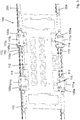
Figure 2 shows a pair of guidance rails of the guiding structure ofFigure 1 , a pair of runner blocks arranged on each guidance rail; -
Figure 3 shows a main plate of a base carriage; -
Figure 4 shows two pairs of secondary runner blocks each mounted on one of the runner blocks ofFigure 2 , a secondary guidance rail arranged to be guided by each pair of secondary runner blocks; -
Figure 5 shows in detail a structure flexibly connecting a secondary runner block to one of the runner blocks ofFigure 2 , and a mounting element for mounting an intermediate carriage onto a secondary guidance rail; -
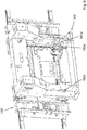
Figure 6 shows an assembly of a base carriage and an intermediate carriage, and -
Figure 7 shows an assembly of an intermediate carriage and a sub-carriage. - With reference to
Figure 1 , a scanning-type inkjet printer comprises aninkjet print head 3 mounted on aprint head carriage 2 arranged to move relative to arecording medium 4 along a first horizontal axis Y while being guided by a guidingstructure 1. - Either the guiding
structure 1 or therecording medium 4 is movably arranged in order for the guidingstructure 1 and therecording medium 4 to be moved relative to each other along a second horizontal axis X normal to the first horizontal axis Y. - In operation, a swath of ink droplets is deposited onto the
recording medium 4 by theprint head 3 ejecting sequences of ink droplets towards therecording medium 4 while theprint head carriage 2 is moving along the first horizontal axis Y, guided by the guidingstructure 1. - In between the deposition of different swaths, the guiding
structure 1 and therecording medium 4 are moved relative to each other along the second horizontal axis X, so that multiple swaths of ink droplets deposited onto therecording medium 4 can form a complete printed image. - In the shown embodiment, the guiding
structure 1 comprises an elongatedmain part 10, oriented to extend along the first horizontal axis Y. - The guiding
structure 1 further comprises a pair ofprimary guidance rails front face 11 of themain part 10 oriented orthogonally with respect to the second horizontal axis X. Theprimary guidance rails - With reference to
Figure 2 , a pair ofprimary runner blocks primary guidance rails - Each
primary runner block primary guidance rail - Each
primary runner block primary guidance rail primary runner block primary runner block rail - With reference to
Figure 3 , abase carriage 100 of theprint head carriage 2 comprises amain plate 110 oriented orthogonally with respect to the second horizontal axis X, themain plate 110 havingdifferent plate sections primary runner blocks - Each
plate section main section 112 of themain plate 110 via one or moreflexible bridges flexible bridges plate section main section 112. - Each
flexible bridge section 115 of themain plate 110 having amiddle portion 115b of a certain width extending in between twoend portions section 115 being able to flex about various axes, including an axis normal to thesection 115 at each of theend portions flexible bridge end portion 115a to theother end portion 115c, allowingplate sections respective end portions - In the shown embodiment, the
plate sections 111a positioned at theprimary runner blocks 120a arranged on the bottomprimary guidance rail 20a are each connected to themain section 112 by aflexible bridge 113 extending along the first horizontal axis Y and aflexible bridge 114 extending along the vertical axis Z. Arespective plate section 111a is thereby constrained relative to themain section 112 in translational degrees of freedom along the first horizontal axis Y and the vertical axis Z, and allowed to move relative to themain section 112 along the second horizontal axis X, as well as in all rotational degrees of freedom. - The
plate sections 111b positioned at theprimary runner blocks 120b arranged on the topprimary guidance rail 20b are each connected to themain section 112 only by aflexible bridge 113 extending along the first horizontal axis Y. Arespective plate section 111b is thereby constrained relative to themain section 112 in a translational degree of freedom along the first horizontal axis Y, and allowed to move relative to themain section 112 along the second horizontal axis X and the vertical axis Z, as well as in all rotational degrees of freedom. - With reference to
Figure 4 , thebase carriage 100 further comprises two pairs ofsecondary runner blocks secondary runner block primary runner blocks secondary guidance rails 140, eachsecondary guidance rail 140 arranged to be guided by a respective pair of thesecondary runner blocks - Each pair of a
secondary runner blocks runner block 130a mounted on aprimary runner block 120a arranged on the bottomprimary guidance rail 20a, and onerunner block 130b mounted on aprimary runner block 120b arranged on the topprimary guidance rail 20b. - Each
secondary guidance rail 140 is oriented along the vertical axis Z, and configured to slide along said vertical axis Z relative to a respective pair ofsecondary runner blocks rail 140. - Each
secondary runner block secondary guidance rail 140 in such a way, that the translational degrees of freedom of theguidance rail 140 along the two horizontal axes X, Y and the rotational degrees of freedom about all of the three axes X, Y, Z are constrained relative to therunner block - Each
section main plate 110 positioned at a respectiveprimary runner block secondary runner block primary runner block different plate sections main section 112 of themain plate 110 as described, themain plate 110 is not overly constrained by theplate sections primary guidance rails main plate 110 of thebase carriage 100 and themain part 10 of the guidingstructure 1. - Each
secondary runner block primary runner block flexible structure 150, theflexible structure 150 allowing for a certain motion of thesecondary runner block primary runner block - With reference to
Figure 5 , eachflexible structure 150 comprises a pair offlexing plates 151 oriented orthogonally with respect to the first horizontal axis Y, eachflexing plate 151 having a relativelythin middle portion 151b extending along the second horizontal axis X in between twowider end portions flexing plate 151 being able to flex about the first horizontal axis Y at themiddle portion 151b, the pair offlexing plates 151, arranged on opposite sides of asecondary runner block 130b along the first horizontal axis Y, constrains such asecondary runner block 130b relative to the connectedprimary runner block 120b in respect of a translational degree of freedom along the second horizontal axis X while providing a rotational degree of freedom about the first horizontal axis Y. - One
end portion 151a of eachflexing plate 151 is connected to aprimary runner block 120b via a pair offlexing plate sections 152 arranged at a top end and a bottom end of theend portion 151a, eachflexing plate section 152 oriented orthogonally with respect to the vertical axis Z. Eachflexing plate section 152 being able to flex about the first horizontal axis Y, each pair offlexing plate sections 152 connected to aflexing plate 151 allows asecondary runner block 130b fixed to theother end portion 151b of theflexing plate 151 to translate to a limited extent along the vertical axis Z relative to theprimary runner block 120b. - The one
end portion 151a of eachflexing plate 151 being able to flex about the vertical axis Z relative to theflexing plate sections 152 arranged at the top end and the bottom end, asecondary runner block 130b fixed to theother end portion 151b is also allowed to rotate to some extent about the vertical axis Z relative to theprimary runner block 120b. - The one
end portion 151a of eachflexing plate 151 being able to flex about the first horizontal axis X, asecondary runner block 130b fixed to theother end portion 151b is also allowed to translate to some extent along the first horizontal axis Y relative to theprimary runner block 120b, and to rotate to some extent about the second horizontal axis X relative to theprimary runner block 120b. - In summary, each
flexible structure 150 constrains asecondary runner block primary runner block secondary runner block primary runner block primary runner block - By each
flexible structure 150 allowing for a certain motion between asecondary runner block primary runner block secondary guidance rails 140 are not overly constrained by thesecondary runner blocks primary runner block primary guidance rails secondary guidance rails 140. - With further reference to
Figure 4 , the twosecondary guidance rails 140 are mutually connected by adriving plate 160 extending in parallel to themain plate 110. - The
base carriage 100 comprises a first pair oflinear motors 170 each connected to adifferent end 163 of thedriving plate 160 for driving saidend 163 to move along the vertical axis Z relative to themain plate 110, the twolinear motors 170 thereby being able also to drive the twosecondary guidance rails 140 to move along the vertical axis Z relative to themain plate 110 together with thedriving plate 160. - The two
linear motors 170 having different positions along the first horizontal axis Y allows the twolinear motors 170 also to tilt thedriving plate 160 to some extent about the second horizontal axis X, by thelinear motors 170 driving thedifferent ends 163 of thedriving plate 160 towards different positions along the vertical axis Z. - Limited tilting of the
driving plate 160 about the second horizontal axis X is enabled by eachsecondary guidance rail 140 being connected to amain section 162 of thedriving plate 160 by aflexible section 161 allowing themain section 162 to tilt about the second horizontal X relative to therespective guidance rail 140. - With further reference to
Figure 5 as well asFigure 6 , eachsecondary guidance rail 140 carries a pair ofmounting elements intermediate carriage 300 to be mounted onto the pair ofsecondary guidance rails 140, themounting elements guidance rail 140 along the vertical axis Z. - Each
upper mounting element 180b serves to hold a top end of a respective first leaf spring (not shown) connecting theintermediate carriage 300 to thebase carriage 100, the first leaf spring having at least a portion extending along the vertical axis Z oriented orthogonally with respect to the first horizontal axis Y to allow a bottom end of the first leaf spring, fixed to a part of theintermediate carriage 300, to move along the first horizontal axis Y while a translation along the vertical axis Z is constrained. - Each
lower mounting element 180a serves to hold a back end of a respectivesecond leaf spring 181a connecting theintermediate carriage 300 to thebase carriage 100, thesecond leaf spring 181a having at least a portion extending along the second horizontal axis X oriented orthogonally with respect to the vertical axis Z as well as a portion extending along the second horizontal axis X oriented orthogonally with respect to the first horizontal axis Y, to allow a front end of thesecond leaf spring 181a, fixed to another part of theintermediate carriage 300, to move along both the first horizontal axis Y and the vertical axis Z while a translation along the second horizontal axis X is constrained. - A translation of the
intermediate carriage 300 as a whole relative to thebase carriage 100 along the first horizontal axis Y is constrained by a rod (not shown) connecting yet another part of theintermediate carriage 300 to thebase carriage 100, extending along the first horizontal axis Y. - Being mounted as described, the
intermediate carriage 300 is minimally constrained with respect to translations relative to thebase carriage 100 along the first horizontal axis Y and the vertical axis Z, which allows for theintermediate carriage 300 and thebase carriage 100 to be subject to different amounts of thermal expansion. At the same time, theintermediate carriage 300 is fixedly constrained with respect to a translation relative to thebase carriage 100 along the second horizontal axis X, which allows for horizontal reaction forces resulting from thesub-carriage 200 being driven to move relative to theintermediate carriage 300 along the second horizontal axis X to be transferred, via the pair ofsecondary guidance rails 140, thesecondary runner blocks flexible structures 150, and theprimary runner blocks guidance rails main part 10 of the guidingstructure 1. - With reference to
Figure 7 , a sub-carriage 200 mounted on theintermediate carriage 300 comprises asupport plate 210 for supporting at least one print head, or a substructure carrying at least one print head, with a portion of the print head facing arecording medium 4, thesupport plate 210 horizontally oriented and arranged at a bottom of the sub-carriage 200. - The
support plate 210 is connected to amain structure 310 of theintermediate carriage 300 via a pair ofleaf spring structures leaf spring structures support plate 210 at opposite ends 211, 212 thereof, on opposite sides of anarea 213 for receiving a print head. - A
leaf spring structure 220 connecting afirst end 211 of thesupport plate 210 to themain structure 310 comprises a pair ofleaf springs 221 oriented in parallel to each other orthogonally with respect to the first horizontal axis Y, and twoleaf spring sections 222 oriented orthogonally with respect to the second horizontal axis X, eachleaf spring section 222 connecting the pair ofleaf springs 221 to one of thesupport plate 210 and themain structure 310. The pair ofleaf springs 221 is configured to flex about the second horizontal axis X, providing thefirst end 211 of thesupport plate 210 with a translational degree of freedom relative to themain structure 310 along the first horizontal axis Y, thereby enabling thesupport plate 210 and themain structure 310 to be subject to different amounts of thermal expansion. The twoleaf spring sections 222 are each configured to flex about the first horizontal axis Y, enabling thefirst end 211 of thesupport plate 213 to be moved along the second horizontal axis X. - A
leaf spring structure 230 connecting thesecond end 212 of thesupport plate 210 to themain structure 310 comprises a relatively stiffmiddle section 231, and twoleaf springs 232 oriented orthogonally with respect to the second horizontal axis X, eachleaf spring 232 connecting themiddle section 231 to one of thesupport plate 210 and themain structure 310. Eachleaf spring 232 is configured to flex about the first horizontal axis Y, enabling also thesecond end 212 of thesupport plate 210 to be moved along the second horizontal axis X. The relatively stiffmiddle section 231 keeps thesecond end 212 of thesupport plate 210 fixed relative to themain structure 310 along the first horizontal axis Y. - The
leaf spring structures support plate 210 about the second horizontal axis X. - A rotation of the sub-carriage 200 relative to the
intermediate carriage 300 about the first horizontal axis Y is constrained by aflexible rod 240 connecting thesupport plate 210 to themain structure 310, extending along the vertical axis Z, positioned in between the twoleaf spring structures leaf spring structures - A
top end 241 of therod 240 is connected to alever 250 mounted on themain structure 310 of theintermediate carriage 300, thelever 250 operable for accurately adjusting a position of saidtop end 241 along the vertical axis Z in order to control a rotational position of thesupport plate 210 about the first horizontal axis Y, thesupport plate 210 connected to the other end of therod 240. - A position of each
end support plate 210 along the second horizontal axis X can be adjusted by a second pair oflinear motors 260, eachlinear motor 260 positioned on themain structure 310 and connected to one of theends respective end main structure 310 along said axis X. - The two
linear motors 260 having different positions along the first horizontal axis Y allows the twolinear motors 260 also to rotate thesupport plate 210 to some extent about the vertical axis Z, by thelinear motors 260 driving the different ends 211, 212 of thesupport plate 210 towards different positions along the second horizontal axis X. - Each
linear motor - The translational degree of freedom along the vertical axis Z of the
intermediate carriage 300 relative to thebase carriage 100 allows anassembly - Before printing, by control of the first pair of
linear motors 170, theintermediate carriage 300 is moved relative to thebase carriage 100 in order to set a print head mounted on the sub-carriage 200 at a suitable height above a supporting surface for supporting arecording medium 4. - By control of the
same motors 170, before printing, the sub-carriage 200 may also be tilted to some extent about the second horizontal axis X, in order to compensate for any inaccuracies in theassembly - Aligning the sub-carriage 200 before printing may also comprise the tilting of the sub-carriage 200 about the first horizontal axis Y by control of the
lever 250. - The translational degree of freedom along the second horizontal axis X of the sub-carriage 200 relative to the
intermediate carriage 300 allows the position of a print head relative to the guidingstructure 1 to be continuously corrected in order for the print head to follow a straight path in parallel to the guidingstructure 1, despite any inaccuracies in themain part 10 of the guidingstructure 1 causing the guidance rails 20a, 20b not to be perfectly straight or aligned within a perfectly flat, vertical plane, oriented orthogonally with respect to the second horizontal axis X. - During printing, while the
base carriage 100 moves along the guidingstructure 1, the position of a print head mounted on the sub-carriage 200 is continuously adjusted by the second pair oflinear motors 260 driving the sub-carriage 200 to move in a certain direction along the second horizontal axis X, enabled by the flexibility of theleaf spring structures intermediate carriage 300. - A rotational position of the print head about the vertical axis Z may be adjusted at the same time, by the two
linear motors 260 being controlled independently, for driving the two ends 211, 212 of the sub-carriage 200 to move at different speeds or in different directions along the second horizontal axis X. - In summary, in an
assembly base carriage 100, the sub-carriage 200 and theintermediate carriage 300 are constrained relative to each other in respect of some degrees of freedom, and configured to translate and/or rotate relative to each other in respect of other degrees of freedom. By operation ofcertain actuators certain carriages print head 3 with arecording medium 4 and/or with an axis of carriage motion Y. This enables certain parts of theassembly main part 10 of the guidingstructure 1, parts of the sub-carriage 200, and themain structure 310 of theintermediate carriage 300, to be assembled from relatively inaccurately shaped, but light-weight, and low-cost materials, such as sheet metal parts. Any inaccuracies can then be compensated for by appropriate adjustment of a relative position and/or orientation as described. - It is to be understood that the disclosed embodiments are merely exemplary of the invention, which can be embodied in various forms. Specific structural and functional details are not to be interpreted as limiting, but merely as a basis for the claims and as a teaching for one skilled in the art to variously employ the present invention in virtually any appropriately detailed structure. In particular, features presented and described in separate dependent claims may be applied in combination, and any advantageous combination of such claims is herewith disclosed.
- The invention being thus described, it will be obvious that the same may be varied in many ways. Such variations are not to be regarded as a departure from the spirit and scope of the invention, and all such modifications as would be obvious to one skilled in the art are intended to be included within the scope of the following claims.
Claims (15)
- Assembly of a guiding structure (1) and a print head carriage (2), the print head carriage (2) comprising a base carriage (100) controllably movable relative to the guiding structure (1) along a first horizontal axis (Y), the print head carriage (2) comprising a sub-carriage (200) controllably movable relative to the base carriage (100) along a second horizontal axis (X),
wherein the print head carriage (2) comprises an intermediate carriage (300) controllably movable relative to the base carriage (100) along a vertical axis (Z), the sub-carriage (200) mounted on the intermediate carriage (300) for moving together with the intermediate carriage (300) relative to the base carriage (100), the sub-carriage (200) controllably movable relative to the intermediate carriage (300) along the second horizontal axis (X). - Assembly according to claim 1, wherein the intermediate carriage (300) is controllably tiltable relative to the base carriage (100) about the second horizontal axis (X), the sub-carriage (200) is controllably tiltable relative to the intermediate carriage (300) about the first horizontal axis (Y), and/or the sub-carriage (200) is controllably rotatable relative to the intermediate carriage (300) about the vertical axis (Z).
- Assembly according to claim 1 or 2, the guiding structure (1) comprising a pair of primary guidance rails (20a, 20b) extending along the first horizontal axis (Y), a pair of primary runner blocks (120a, 120b) arranged on each guidance rail (20a, 20b), the base carriage (100) comprising a pair of secondary guidance rails (140) extending along the vertical axis (Z), each secondary guidance rail (140) arranged to be guided by a pair of secondary runner blocks (130a, 130b), each secondary runner block (130a, 130b) mounted on a respective one of the primary runner blocks (120a, 120b).
- Assembly according to claim 3, wherein each secondary runner block (130a, 130b) is connected to a respective primary runner block (120a, 120b) via a flexible structure (150).
- Assembly according to claim 4, wherein the flexible structure (150) constrains the secondary runner block (130a, 130b) relative to the primary runner block (120a, 120b) in respect of a translational degree of freedom along the second horizontal axis (X).
- Assembly according to claim 4 or 5, wherein the flexible structure (150) provides the secondary runner block (130a, 130b) with translational degrees of freedom relative to the primary runner block (120a, 120b) along the first horizontal axis (Y) and the vertical axis (Z), and rotational degrees of freedom relative to the primary runner block (120a, 120b) about all three axes (X, Y, Z).
- Assembly according to one of claims 3 to 6, the base carriage (100) comprising a main plate (110) having different sections (111a, 111b) each fixed to a different runner block (120a, 120b, 130a, 130b), each plate section (111a, 111b) connected to a main section (112) of the main plate (110) via one or more flexible bridges (113, 114) allowing for a certain motion of a respective plate section (111a, 111b) relative to the main section (112).
- Assembly according to claim 7, the main plate (110) comprising two plate sections (111a) constrained relative to the main section (112) in translational degrees of freedom along the first horizontal axis (Y) and the vertical axis (Z), and two further plate sections (111b) constrained relative to the main section (112) in a translational degree of freedom along the first horizontal axis (Y) and allowed to move relative to the main section (112) along the vertical axis (Z).
- Assembly according to claim 7 or 8, wherein each plate section (111a, 111b) is fixed to a secondary runner block (130a, 130b).
- Assembly according to one of the preceding claims, wherein the intermediate carriage (300) is minimally constrained with respect to translations relative to the base carriage (100) along the first horizontal axis (Y) and the vertical axis (Z), and fixedly constrained with respect to a translation relative to the base carriage (100) along the second horizontal axis (X).
- Assembly according to one of the preceding claims, comprising at least one leaf spring structure (220, 230) connecting the sub-carriage (200) to the intermediate carriage (300), the leaf spring structure (220, 230) providing the sub-carriage (200) with a translational degree of freedom relative to the intermediate carriage (300) along the second horizontal axis (X).
- Assembly according to one of the preceding claims, comprising at least one leaf spring structure (220) connecting the sub-carriage (200) to the intermediate carriage (300), the leaf spring structure (220) providing an end (211) of the sub-carriage (200) with a translational degree of freedom relative to the intermediate carriage (300) along the first horizontal axis (Y).
- Assembly according to one of the preceding claims, comprising two actuators (170) for driving the intermediate carriage (300) to move relative to the base carriage (100) along the vertical axis (Z), the two actuators (170) having different positions along the first horizontal axis (Y).
- Assembly according to one of the preceding claims, comprising two actuators (260) for driving the sub-carriage (200) to move relative to the intermediate carriage (300) along the second horizontal axis (X), the two actuators (260) having different positions along the first horizontal axis (Y).
- Printer comprising an assembly according to one of the preceding claims.
Priority Applications (2)
| Application Number | Priority Date | Filing Date | Title |
|---|---|---|---|
| EP18188394.3A EP3608114B1 (en) | 2018-08-10 | 2018-08-10 | Assembly of a guiding structure and a print head carriage |
| US16/524,892 US10875328B2 (en) | 2018-08-10 | 2019-07-29 | Assembly of a guiding structure and a print head carriage |
Applications Claiming Priority (1)
| Application Number | Priority Date | Filing Date | Title |
|---|---|---|---|
| EP18188394.3A EP3608114B1 (en) | 2018-08-10 | 2018-08-10 | Assembly of a guiding structure and a print head carriage |
Publications (3)
| Publication Number | Publication Date |
|---|---|
| EP3608114A1 true EP3608114A1 (en) | 2020-02-12 |
| EP3608114B1 EP3608114B1 (en) | 2023-06-07 |
| EP3608114C0 EP3608114C0 (en) | 2023-06-07 |
Family
ID=63209229
Family Applications (1)
| Application Number | Title | Priority Date | Filing Date |
|---|---|---|---|
| EP18188394.3A Active EP3608114B1 (en) | 2018-08-10 | 2018-08-10 | Assembly of a guiding structure and a print head carriage |
Country Status (2)
| Country | Link |
|---|---|
| US (1) | US10875328B2 (en) |
| EP (1) | EP3608114B1 (en) |
Families Citing this family (3)
| Publication number | Priority date | Publication date | Assignee | Title |
|---|---|---|---|---|
| EP4197801B1 (en) * | 2021-12-20 | 2024-12-04 | Canon Production Printing Holding B.V. | Printer and guidance rail for a print head carriage |
| CN219427744U (en) * | 2023-01-10 | 2023-07-28 | 驱动数码电子(广东)有限公司 | Ink-jet printing structure |
| JP2024138718A (en) * | 2023-03-27 | 2024-10-09 | 株式会社リコー | Printing device |
Citations (3)
| Publication number | Priority date | Publication date | Assignee | Title |
|---|---|---|---|---|
| US20040250760A1 (en) * | 2001-09-28 | 2004-12-16 | Makoto Goto | Nozzle head, nozzle head holder, and droplet jet patterning device |
| JP2008062534A (en) * | 2006-09-08 | 2008-03-21 | Mimaki Engineering Co Ltd | Printer head of printer device |
| JP6284601B1 (en) * | 2016-10-14 | 2018-02-28 | 東友科技股▲ふん▼有限公司Teco Image Systems Co.,Ltd. | Print head pitch adjustment device |
Family Cites Families (1)
| Publication number | Priority date | Publication date | Assignee | Title |
|---|---|---|---|---|
| EP3395576B1 (en) * | 2017-04-26 | 2021-10-27 | Ricoh Company, Ltd. | Liquid discharge apparatus |
-
2018
- 2018-08-10 EP EP18188394.3A patent/EP3608114B1/en active Active
-
2019
- 2019-07-29 US US16/524,892 patent/US10875328B2/en active Active
Patent Citations (3)
| Publication number | Priority date | Publication date | Assignee | Title |
|---|---|---|---|---|
| US20040250760A1 (en) * | 2001-09-28 | 2004-12-16 | Makoto Goto | Nozzle head, nozzle head holder, and droplet jet patterning device |
| JP2008062534A (en) * | 2006-09-08 | 2008-03-21 | Mimaki Engineering Co Ltd | Printer head of printer device |
| JP6284601B1 (en) * | 2016-10-14 | 2018-02-28 | 東友科技股▲ふん▼有限公司Teco Image Systems Co.,Ltd. | Print head pitch adjustment device |
Also Published As
| Publication number | Publication date |
|---|---|
| EP3608114B1 (en) | 2023-06-07 |
| EP3608114C0 (en) | 2023-06-07 |
| US20200047527A1 (en) | 2020-02-13 |
| US10875328B2 (en) | 2020-12-29 |
Similar Documents
| Publication | Publication Date | Title |
|---|---|---|
| US10875328B2 (en) | Assembly of a guiding structure and a print head carriage | |
| KR101175935B1 (en) | Printable substrate and nozzle alignment system | |
| KR101188112B1 (en) | Dynamic printhead alignment assembly | |
| RU2538864C2 (en) | Single-pass inkjet printer | |
| WO2015144574A2 (en) | Mounting structure for a plurality of print head units | |
| KR101066585B1 (en) | Rotatable Printhead Array | |
| JP5804921B2 (en) | Carriage and inkjet device | |
| KR100948563B1 (en) | A print head mounting assembly and method for mounting a print head onto a carriage framework | |
| JP2013014046A (en) | Inkjet recording method and inkjet recording apparatus | |
| CN101171138B (en) | Segmented receiver platform and stroke distance calibration for digital printers | |
| US20080273910A1 (en) | Print Head Shuttle with Active Cooling | |
| JP4990523B2 (en) | Print head | |
| EP1676711B1 (en) | Printhead carriage | |
| JP4839079B2 (en) | Scanning printer frame structure | |
| EP1674280B1 (en) | Frame structure of a scanning-type printer | |
| US20230302825A1 (en) | Mounting systems for print medium supporting structures |
Legal Events
| Date | Code | Title | Description |
|---|---|---|---|
| PUAI | Public reference made under article 153(3) epc to a published international application that has entered the european phase |
Free format text: ORIGINAL CODE: 0009012 |
|
| STAA | Information on the status of an ep patent application or granted ep patent |
Free format text: STATUS: THE APPLICATION HAS BEEN PUBLISHED |
|
| AK | Designated contracting states |
Kind code of ref document: A1 Designated state(s): AL AT BE BG CH CY CZ DE DK EE ES FI FR GB GR HR HU IE IS IT LI LT LU LV MC MK MT NL NO PL PT RO RS SE SI SK SM TR |
|
| AX | Request for extension of the european patent |
Extension state: BA ME |
|
| RAP1 | Party data changed (applicant data changed or rights of an application transferred) |
Owner name: CANON PRODUCTION PRINTING HOLDING B.V. |
|
| STAA | Information on the status of an ep patent application or granted ep patent |
Free format text: STATUS: REQUEST FOR EXAMINATION WAS MADE |
|
| 17P | Request for examination filed |
Effective date: 20200812 |
|
| RBV | Designated contracting states (corrected) |
Designated state(s): AL AT BE BG CH CY CZ DE DK EE ES FI FR GB GR HR HU IE IS IT LI LT LU LV MC MK MT NL NO PL PT RO RS SE SI SK SM TR |
|
| RAP1 | Party data changed (applicant data changed or rights of an application transferred) |
Owner name: CANON PRODUCTION PRINTING HOLDING B.V. |
|
| GRAP | Despatch of communication of intention to grant a patent |
Free format text: ORIGINAL CODE: EPIDOSNIGR1 |
|
| STAA | Information on the status of an ep patent application or granted ep patent |
Free format text: STATUS: GRANT OF PATENT IS INTENDED |
|
| INTG | Intention to grant announced |
Effective date: 20220602 |
|
| GRAJ | Information related to disapproval of communication of intention to grant by the applicant or resumption of examination proceedings by the epo deleted |
Free format text: ORIGINAL CODE: EPIDOSDIGR1 |
|
| STAA | Information on the status of an ep patent application or granted ep patent |
Free format text: STATUS: REQUEST FOR EXAMINATION WAS MADE |
|
| GRAP | Despatch of communication of intention to grant a patent |
Free format text: ORIGINAL CODE: EPIDOSNIGR1 |
|
| STAA | Information on the status of an ep patent application or granted ep patent |
Free format text: STATUS: GRANT OF PATENT IS INTENDED |
|
| INTC | Intention to grant announced (deleted) | ||
| INTG | Intention to grant announced |
Effective date: 20221021 |
|
| GRAS | Grant fee paid |
Free format text: ORIGINAL CODE: EPIDOSNIGR3 |
|
| GRAA | (expected) grant |
Free format text: ORIGINAL CODE: 0009210 |
|
| STAA | Information on the status of an ep patent application or granted ep patent |
Free format text: STATUS: THE PATENT HAS BEEN GRANTED |
|
| AK | Designated contracting states |
Kind code of ref document: B1 Designated state(s): AL AT BE BG CH CY CZ DE DK EE ES FI FR GB GR HR HU IE IS IT LI LT LU LV MC MK MT NL NO PL PT RO RS SE SI SK SM TR |
|
| REG | Reference to a national code |
Ref country code: GB Ref legal event code: FG4D |
|
| REG | Reference to a national code |
Ref country code: CH Ref legal event code: EP Ref country code: AT Ref legal event code: REF Ref document number: 1573891 Country of ref document: AT Kind code of ref document: T Effective date: 20230615 |
|
| REG | Reference to a national code |
Ref country code: DE Ref legal event code: R096 Ref document number: 602018050732 Country of ref document: DE |
|
| U01 | Request for unitary effect filed |
Effective date: 20230703 |
|
| U07 | Unitary effect registered |
Designated state(s): AT BE BG DE DK EE FI FR IT LT LU LV MT NL PT SE SI Effective date: 20230711 |
|
| REG | Reference to a national code |
Ref country code: LT Ref legal event code: MG9D |
|
| PG25 | Lapsed in a contracting state [announced via postgrant information from national office to epo] |
Ref country code: NO Free format text: LAPSE BECAUSE OF FAILURE TO SUBMIT A TRANSLATION OF THE DESCRIPTION OR TO PAY THE FEE WITHIN THE PRESCRIBED TIME-LIMIT Effective date: 20230907 Ref country code: ES Free format text: LAPSE BECAUSE OF FAILURE TO SUBMIT A TRANSLATION OF THE DESCRIPTION OR TO PAY THE FEE WITHIN THE PRESCRIBED TIME-LIMIT Effective date: 20230607 |
|
| U20 | Renewal fee for the european patent with unitary effect paid |
Year of fee payment: 6 Effective date: 20231023 |
|
| PG25 | Lapsed in a contracting state [announced via postgrant information from national office to epo] |
Ref country code: RS Free format text: LAPSE BECAUSE OF FAILURE TO SUBMIT A TRANSLATION OF THE DESCRIPTION OR TO PAY THE FEE WITHIN THE PRESCRIBED TIME-LIMIT Effective date: 20230607 Ref country code: HR Free format text: LAPSE BECAUSE OF FAILURE TO SUBMIT A TRANSLATION OF THE DESCRIPTION OR TO PAY THE FEE WITHIN THE PRESCRIBED TIME-LIMIT Effective date: 20230607 Ref country code: GR Free format text: LAPSE BECAUSE OF FAILURE TO SUBMIT A TRANSLATION OF THE DESCRIPTION OR TO PAY THE FEE WITHIN THE PRESCRIBED TIME-LIMIT Effective date: 20230908 |
|
| PG25 | Lapsed in a contracting state [announced via postgrant information from national office to epo] |
Ref country code: SK Free format text: LAPSE BECAUSE OF FAILURE TO SUBMIT A TRANSLATION OF THE DESCRIPTION OR TO PAY THE FEE WITHIN THE PRESCRIBED TIME-LIMIT Effective date: 20230607 |
|
| PG25 | Lapsed in a contracting state [announced via postgrant information from national office to epo] |
Ref country code: IS Free format text: LAPSE BECAUSE OF FAILURE TO SUBMIT A TRANSLATION OF THE DESCRIPTION OR TO PAY THE FEE WITHIN THE PRESCRIBED TIME-LIMIT Effective date: 20231007 |
|
| PG25 | Lapsed in a contracting state [announced via postgrant information from national office to epo] |
Ref country code: SM Free format text: LAPSE BECAUSE OF FAILURE TO SUBMIT A TRANSLATION OF THE DESCRIPTION OR TO PAY THE FEE WITHIN THE PRESCRIBED TIME-LIMIT Effective date: 20230607 Ref country code: SK Free format text: LAPSE BECAUSE OF FAILURE TO SUBMIT A TRANSLATION OF THE DESCRIPTION OR TO PAY THE FEE WITHIN THE PRESCRIBED TIME-LIMIT Effective date: 20230607 Ref country code: RO Free format text: LAPSE BECAUSE OF FAILURE TO SUBMIT A TRANSLATION OF THE DESCRIPTION OR TO PAY THE FEE WITHIN THE PRESCRIBED TIME-LIMIT Effective date: 20230607 Ref country code: IS Free format text: LAPSE BECAUSE OF FAILURE TO SUBMIT A TRANSLATION OF THE DESCRIPTION OR TO PAY THE FEE WITHIN THE PRESCRIBED TIME-LIMIT Effective date: 20231007 Ref country code: CZ Free format text: LAPSE BECAUSE OF FAILURE TO SUBMIT A TRANSLATION OF THE DESCRIPTION OR TO PAY THE FEE WITHIN THE PRESCRIBED TIME-LIMIT Effective date: 20230607 |
|
| PG25 | Lapsed in a contracting state [announced via postgrant information from national office to epo] |
Ref country code: PL Free format text: LAPSE BECAUSE OF FAILURE TO SUBMIT A TRANSLATION OF THE DESCRIPTION OR TO PAY THE FEE WITHIN THE PRESCRIBED TIME-LIMIT Effective date: 20230607 |
|
| REG | Reference to a national code |
Ref country code: DE Ref legal event code: R097 Ref document number: 602018050732 Country of ref document: DE |
|
| PG25 | Lapsed in a contracting state [announced via postgrant information from national office to epo] |
Ref country code: MC Free format text: LAPSE BECAUSE OF FAILURE TO SUBMIT A TRANSLATION OF THE DESCRIPTION OR TO PAY THE FEE WITHIN THE PRESCRIBED TIME-LIMIT Effective date: 20230607 |
|
| REG | Reference to a national code |
Ref country code: CH Ref legal event code: PL |
|
| PG25 | Lapsed in a contracting state [announced via postgrant information from national office to epo] |
Ref country code: MC Free format text: LAPSE BECAUSE OF FAILURE TO SUBMIT A TRANSLATION OF THE DESCRIPTION OR TO PAY THE FEE WITHIN THE PRESCRIBED TIME-LIMIT Effective date: 20230607 |
|
| PLBE | No opposition filed within time limit |
Free format text: ORIGINAL CODE: 0009261 |
|
| STAA | Information on the status of an ep patent application or granted ep patent |
Free format text: STATUS: NO OPPOSITION FILED WITHIN TIME LIMIT |
|
| PG25 | Lapsed in a contracting state [announced via postgrant information from national office to epo] |
Ref country code: CH Free format text: LAPSE BECAUSE OF NON-PAYMENT OF DUE FEES Effective date: 20230831 |
|
| 26N | No opposition filed |
Effective date: 20240308 |
|
| REG | Reference to a national code |
Ref country code: IE Ref legal event code: MM4A |
|
| PG25 | Lapsed in a contracting state [announced via postgrant information from national office to epo] |
Ref country code: IE Free format text: LAPSE BECAUSE OF NON-PAYMENT OF DUE FEES Effective date: 20230810 |
|
| PG25 | Lapsed in a contracting state [announced via postgrant information from national office to epo] |
Ref country code: IE Free format text: LAPSE BECAUSE OF NON-PAYMENT OF DUE FEES Effective date: 20230810 |
|
| U20 | Renewal fee for the european patent with unitary effect paid |
Year of fee payment: 7 Effective date: 20240902 |
|
| PG25 | Lapsed in a contracting state [announced via postgrant information from national office to epo] |
Ref country code: CY Free format text: LAPSE BECAUSE OF FAILURE TO SUBMIT A TRANSLATION OF THE DESCRIPTION OR TO PAY THE FEE WITHIN THE PRESCRIBED TIME-LIMIT; INVALID AB INITIO Effective date: 20180810 |
|
| PG25 | Lapsed in a contracting state [announced via postgrant information from national office to epo] |
Ref country code: HU Free format text: LAPSE BECAUSE OF FAILURE TO SUBMIT A TRANSLATION OF THE DESCRIPTION OR TO PAY THE FEE WITHIN THE PRESCRIBED TIME-LIMIT; INVALID AB INITIO Effective date: 20180810 |
|
| U20 | Renewal fee for the european patent with unitary effect paid |
Year of fee payment: 8 Effective date: 20250901 |
|
| PGFP | Annual fee paid to national office [announced via postgrant information from national office to epo] |
Ref country code: GB Payment date: 20250820 Year of fee payment: 8 |
|
| PG25 | Lapsed in a contracting state [announced via postgrant information from national office to epo] |
Ref country code: TR Free format text: LAPSE BECAUSE OF FAILURE TO SUBMIT A TRANSLATION OF THE DESCRIPTION OR TO PAY THE FEE WITHIN THE PRESCRIBED TIME-LIMIT Effective date: 20230607 |