EP3608103B1 - Method and laminating apparatus for laminating a stack consisting of several substrate layers to form a composite body - Google Patents
Method and laminating apparatus for laminating a stack consisting of several substrate layers to form a composite body Download PDFInfo
- Publication number
- EP3608103B1 EP3608103B1 EP19188163.0A EP19188163A EP3608103B1 EP 3608103 B1 EP3608103 B1 EP 3608103B1 EP 19188163 A EP19188163 A EP 19188163A EP 3608103 B1 EP3608103 B1 EP 3608103B1
- Authority
- EP
- European Patent Office
- Prior art keywords
- laminating
- stack
- heating
- cooling
- holding
- Prior art date
- Legal status (The legal status is an assumption and is not a legal conclusion. Google has not performed a legal analysis and makes no representation as to the accuracy of the status listed.)
- Active
Links
- 238000010030 laminating Methods 0.000 title claims description 123
- 239000000758 substrate Substances 0.000 title claims description 40
- 239000002131 composite material Substances 0.000 title claims description 26
- 238000000034 method Methods 0.000 title claims description 19
- 238000010438 heat treatment Methods 0.000 claims description 96
- 238000001816 cooling Methods 0.000 claims description 88
- 238000003475 lamination Methods 0.000 claims description 44
- 230000008569 process Effects 0.000 claims description 7
- 238000012545 processing Methods 0.000 claims description 4
- 230000005540 biological transmission Effects 0.000 claims 1
- 238000006073 displacement reaction Methods 0.000 claims 1
- 210000002414 leg Anatomy 0.000 description 7
- 230000032258 transport Effects 0.000 description 6
- 230000007246 mechanism Effects 0.000 description 5
- 230000008859 change Effects 0.000 description 4
- 238000003825 pressing Methods 0.000 description 4
- 238000012546 transfer Methods 0.000 description 3
- 230000008901 benefit Effects 0.000 description 2
- 239000000463 material Substances 0.000 description 2
- 229920001169 thermoplastic Polymers 0.000 description 2
- 239000004416 thermosoftening plastic Substances 0.000 description 2
- 230000003321 amplification Effects 0.000 description 1
- 238000010276 construction Methods 0.000 description 1
- 239000000498 cooling water Substances 0.000 description 1
- 238000005520 cutting process Methods 0.000 description 1
- 230000006735 deficit Effects 0.000 description 1
- 238000013461 design Methods 0.000 description 1
- 238000011161 development Methods 0.000 description 1
- 230000018109 developmental process Effects 0.000 description 1
- 238000009434 installation Methods 0.000 description 1
- 239000011810 insulating material Substances 0.000 description 1
- 210000003127 knee Anatomy 0.000 description 1
- 238000004519 manufacturing process Methods 0.000 description 1
- 238000012544 monitoring process Methods 0.000 description 1
- 238000003199 nucleic acid amplification method Methods 0.000 description 1
- 229920000515 polycarbonate Polymers 0.000 description 1
- 239000004417 polycarbonate Substances 0.000 description 1
- 238000004801 process automation Methods 0.000 description 1
- 238000004080 punching Methods 0.000 description 1
- 230000000284 resting effect Effects 0.000 description 1
- 238000000926 separation method Methods 0.000 description 1
- 238000004904 shortening Methods 0.000 description 1
- 230000001360 synchronised effect Effects 0.000 description 1
Images


Classifications
-
- B—PERFORMING OPERATIONS; TRANSPORTING
- B32—LAYERED PRODUCTS
- B32B—LAYERED PRODUCTS, i.e. PRODUCTS BUILT-UP OF STRATA OF FLAT OR NON-FLAT, e.g. CELLULAR OR HONEYCOMB, FORM
- B32B41/00—Arrangements for controlling or monitoring lamination processes; Safety arrangements
-
- B—PERFORMING OPERATIONS; TRANSPORTING
- B30—PRESSES
- B30B—PRESSES IN GENERAL
- B30B1/00—Presses, using a press ram, characterised by the features of the drive therefor, pressure being transmitted directly, or through simple thrust or tension members only, to the press ram or platen
- B30B1/10—Presses, using a press ram, characterised by the features of the drive therefor, pressure being transmitted directly, or through simple thrust or tension members only, to the press ram or platen by toggle mechanism
- B30B1/16—Presses, using a press ram, characterised by the features of the drive therefor, pressure being transmitted directly, or through simple thrust or tension members only, to the press ram or platen by toggle mechanism operated by fluid-pressure means
-
- B—PERFORMING OPERATIONS; TRANSPORTING
- B30—PRESSES
- B30B—PRESSES IN GENERAL
- B30B15/00—Details of, or accessories for, presses; Auxiliary measures in connection with pressing
- B30B15/02—Dies; Inserts therefor; Mounting thereof; Moulds
- B30B15/026—Mounting of dies, platens or press rams
-
- B—PERFORMING OPERATIONS; TRANSPORTING
- B30—PRESSES
- B30B—PRESSES IN GENERAL
- B30B15/00—Details of, or accessories for, presses; Auxiliary measures in connection with pressing
- B30B15/06—Platens or press rams
- B30B15/062—Press plates
- B30B15/064—Press plates with heating or cooling means
-
- B—PERFORMING OPERATIONS; TRANSPORTING
- B32—LAYERED PRODUCTS
- B32B—LAYERED PRODUCTS, i.e. PRODUCTS BUILT-UP OF STRATA OF FLAT OR NON-FLAT, e.g. CELLULAR OR HONEYCOMB, FORM
- B32B37/00—Methods or apparatus for laminating, e.g. by curing or by ultrasonic bonding
- B32B37/06—Methods or apparatus for laminating, e.g. by curing or by ultrasonic bonding characterised by the heating method
-
- B—PERFORMING OPERATIONS; TRANSPORTING
- B32—LAYERED PRODUCTS
- B32B—LAYERED PRODUCTS, i.e. PRODUCTS BUILT-UP OF STRATA OF FLAT OR NON-FLAT, e.g. CELLULAR OR HONEYCOMB, FORM
- B32B37/00—Methods or apparatus for laminating, e.g. by curing or by ultrasonic bonding
- B32B37/08—Methods or apparatus for laminating, e.g. by curing or by ultrasonic bonding characterised by the cooling method
-
- B—PERFORMING OPERATIONS; TRANSPORTING
- B32—LAYERED PRODUCTS
- B32B—LAYERED PRODUCTS, i.e. PRODUCTS BUILT-UP OF STRATA OF FLAT OR NON-FLAT, e.g. CELLULAR OR HONEYCOMB, FORM
- B32B39/00—Layout of apparatus or plants, e.g. modular laminating systems
-
- B—PERFORMING OPERATIONS; TRANSPORTING
- B32—LAYERED PRODUCTS
- B32B—LAYERED PRODUCTS, i.e. PRODUCTS BUILT-UP OF STRATA OF FLAT OR NON-FLAT, e.g. CELLULAR OR HONEYCOMB, FORM
- B32B2425/00—Cards, e.g. identity cards, credit cards
-
- B—PERFORMING OPERATIONS; TRANSPORTING
- B32—LAYERED PRODUCTS
- B32B—LAYERED PRODUCTS, i.e. PRODUCTS BUILT-UP OF STRATA OF FLAT OR NON-FLAT, e.g. CELLULAR OR HONEYCOMB, FORM
- B32B2429/00—Carriers for sound or information
Definitions
- the invention relates to a method and a laminating device for laminating a stack consisting of several substrate layers to form a composite body, in particular a document body such as a security document.
- a method and a device for laminating a multilayer security document body are known, in which a thermal press with at least one movable die is used.
- This thermal press comprises an upper movable punch and a lower immovable punch.
- a press pad is assigned to each punch.
- a laminating sheet is provided in each case adjacent to this.
- a stack of substrate layers is provided between the laminating sheets and is laminated by the thermal press.
- several thermal presses are put into operation in series one after the other in order to work in a multi-stage short cycle. For example, two successive heating presses and two successive cooling presses are provided.
- the laminating sheet, the press pad and the stack are preheated.
- the stack is heated to a lamination temperature so that the individual layers are laminated together.
- the stack is cooled in a first stage and then completely cooled in the second cooling press.
- a laminating device for laminating a film tape-like multilayer thermoplastic film arrangement is known.
- This laminating device comprises a heating device and a cooling device, which in the direction of passage of the tape-like film are arranged one behind the other.
- the heating and cooling device in a row, the film arrangement can be laminated in successive steps in one work step and cooled in the next work step in the next station.
- this laminating device after the film arrangement has been laminated, the heating devices arranged on both sides of the film arrangement are each moved apart so that the cooling block is retracted in this upper and lower position of the heating device and the heating block then acts on the cooling block by means of pressing in order to put this cooling block on the Hold down film arrangement for cooling in the laminating position.
- This arrangement is complex in terms of installation space and cost-intensive in terms of construction.
- the invention is based on the object of creating a laminating device and a method for laminating a stack consisting of several substrate layers to form a composite body, in which the lamination time is reduced.
- a lamination device for laminating a stack consisting of several substrate layers to form a composite body, in particular a document body, in which a heating device and a cooling device are provided above the press table, which form a jointly movable upper laminating unit, which are thermally decoupled from one another and For the respective arrangement of the heating device or cooling device in relation to the working position, the upper laminating unit can be moved and in which a lower heating device and a lower cooling device are provided below the press table, which form a jointly movable lower laminating unit, the heating device and the cooling device being thermally decoupled from one another and for respective arrangement of the heating device or cooling device to the working position, the lower laminating unit can be moved.
- This upper and lower laminating unit which is arranged on both sides for stacking, enables the Substrate layers of the stack and more rapid cooling of the laminated composite body, although when moving the upper and lower laminating units, both the heating devices are moved together or simultaneously.
- a synchronous control for moving the upper and lower laminating unit within the laminating device preferably achieves a quick change between laminating and cooling.
- a guide device is preferably provided on the base body, by means of which the upper and lower laminating units can be transferred alternately from a rest position into a working position.
- the heating and cooling devices can be positioned outside of a working position in the lamination device in order to enable quick loading and unloading of the stack. This can be followed by a quick change between the heating and cooling devices by means of a simple movement to the at least one hold-down device and / or laminating sheet, whereby the process times can be reduced.
- the heating device and the cooling device each have a support surface which, in the working position, can be transferred to rest against the at least one hold-down device and / or laminating sheet. This enables full-surface contact and maximum energy transfer to be achieved.
- the heating and cooling device each has a pressure surface opposite the support surface, on which a press ram or a pressure plate of a movable ram can be positioned.
- a press ram or a pressure plate of a movable ram can be positioned.
- the guide device for movably receiving the heating and cooling device is preferably fastened to the base body by means of a spring mounting. As a result, when a pressing force is exerted by means of the press ram on the heating or cooling device, a traversing movement directed towards the stack is made possible. During the change between the heating and cooling device, the guide device can lift the heating and cooling device slightly in relation to the hold-down device, so that a free movement is made possible before the cooling or heating device is then pushed down again to the hold-down device.
- the upper heating and cooling device and the lower heating and cooling device are each preferably designed as a jointly movable laminating unit. This simplifies the control of the laminating device for heating and cooling the stack.
- the thermal separation with an insulating material between the cooling and heating device prevents mutual thermal impairment.
- the heating and cooling devices can be made available at the same time to operating temperature.
- the hold-down device can be designed as a laminating sheet.
- the laminating sheet can also be attached to the hold-down device, preferably replaceable.
- a workpiece carrier can preferably be positioned on the press table, which can be transferred from a transport device to the laminating device for laminating the stack and, after lamination, can be returned to the transport device.
- a laminating device can be integrated into a process automation in which the workpiece carrier transports the stack of substrate layers or the composite body from station to station.
- the press table of the laminating device is preferably designed as a plate with an opening which is attached to the Base body is provided.
- the workpiece carrier can preferably be positioned on the press table. Due to the design of the opening in the press table, the stack received by the workpiece carrier can be acted upon by the respective heating and cooling device of the respective working temperature from an upper side as well as an underside.
- the press table is preferably assigned an upper and a lower hold-down device and / or an upper and lower laminating sheet.
- the laminating sheets can either be moved to the working position or the laminating position so that they are assigned to the press table for laminating the stack, whereas when the laminated stack is cooled, the cooling device can attack the stack directly or with the interposition of a hold-down device.
- the workpiece carrier preferably has a receiving frame with a recess for the at least one substrate layer, and a fixing device for holding the substrate layers in the receiving frame is provided on at least one side edge of the recess.
- This fixing device can preferably be a clamping element.
- this fixing device can also be formed by pins or mandrels which penetrate the respective substrate layer.
- the base body of the laminating device preferably has a C-shaped machine frame which receives the press ram on an upper and a lower leg.
- These C-shaped machine frames have the advantage that there is good accessibility to the press table.
- a workpiece carrier can thereby be passed through the laminating device in a simple manner. As a result, such a lamination device can easily be incorporated into an automation process embed.
- the at least one hold-down device is preferably positioned to the side of the base body and can be transferred from a release position to a holding position with a moving device.
- the independent control of the hold-down device for the cooling and heating device has the advantage that when changing between the heating and cooling device, the laminated stack remains fixed in its position by the hold-down device. As a result, the quality for producing the composite body can be increased.
- the object on which the invention is based is further achieved by a method for laminating a stack consisting of several substrate layers to form a composite body, in which a stack of several substrate layers in a device, in particular in a laminating device, according to one of the preceding embodiments, a press table in a working position is assigned, in which at least one hold-down and / or at least one laminating sheet is transferred into a holding position and the stack is fixed, in which an upper and lower heating device of the upper and lower laminating unit is moved into a working position relative to the press table for heating and lamination of the stack, in which at least one movable stamp presses the upper and lower heating devices onto the at least one hold-down device and / or the at least one laminating sheet during a heating phase and a heat and pressure transfer is initiated into the stack, in which na ch the lamination of the stack, the at least one movable die is moved up and down and the upper and lower heating device is lifted from the press table and then moved into a
- This method enables the stack to be heated to the lamination temperature within a lamination device and the stack to be subsequently cooled, with the stack being fed through the at least one hold-down device and / or the at least one lamination sheet during lamination and cooling and during the change between the cooling device and the heating device is held in a defined position to the press table. This can reduce the process time. The energy for heating and cooling the stack can also be reduced, since only the hold-down device and the laminating sheet act as thermal mass.
- an upper laminating unit which comprises the upper heating and cooling device
- a lower laminating unit which comprises the lower heating and cooling device
- the hold-down device presses on the stack with a preset force. Due to this pre-fixing, the individual substrate layers lie already before the start of the heating phase against each other over the entire surface, whereby a shortening of the heating phase can be achieved.
- the heating and cooling devices each have a working temperature when the laminating device is in operation, even in the rest position. This means that the heating device is also heated to the lamination temperature adjacent to the working position, i.e. in the rest position, and the cooling device is heated to the cooling temperature provided for it, so that the respective process can be carried out immediately after the cooling or heating device has been positioned in the working position .
- the temperature is monitored with at least one temperature sensor, the height of the stack with a distance sensor, the compressive force on the stack with a force sensor and / or the lamination and cooling time with a timer. Process monitoring can thereby be achieved in order to determine at the same time whether the composite body produced is a good part or a reject part.
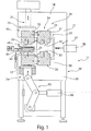
- FIG 1 a schematic side view of a laminating device 11 according to the invention is shown.
- the Figure 2 shows a schematic view from the front of the laminating device 11 according to Figure 1 .
- This laminating device 11 is for laminating one of several Substrate layers 12 existing stack 14 provided to form a composite body.
- This composite body can be designed as a document body, in particular as a security document or value document. Further identification documents or check cards, Visa cards or the like can also be formed by the composite body.
- an ID3 document or an ID1 document can be provided in the case of a security document body.
- the ID1 document can for example consist of 3 to 15 substrate layers and be laminated in a working position, as will be described below.
- Security documents with an RFID chip or other electronic components can also be provided between the substrate layers or within the substrate layers, which form a composite body after lamination.
- This composite body can be cut to a final format in a subsequent cutting and / or punching process. It is also possible for the substrate layers to be added in a final format so that the composite body has a final format after lamination.
- thermoplastic layers in particular polycarbonate, are used as substrate layers 12.
- Other materials that can be laminated with another material by means of pressure and temperature are also used.
- the laminating device 11 comprises a base body 16 which is designed, for example, as a C-shaped machine frame 17.
- This C-shaped machine frame 17 comprises an upper cross member 18 and a lower cross member 20.
- An upper lamination unit 29 and a lower lamination unit 30 are arranged on the upper cross member 18 and the lower cross member 20.
- the upper laminating unit 29 comprises a heating device 31 and a cooling device 32.
- the lower laminating unit 30 also comprises a heating device 31 and a cooling device 32.
- the upper and lower laminating units 29, 30 are preferably constructed identically.
- Press table 19 is provided, which is also attached to the base body 16 or is assigned to the base body 16 between the upper and lower laminating units 29, 30.
- the punch 21 can be actuated to move by a press.
- a press This can preferably be a hydraulic press, a pressure cylinder or the like.
- a toggle lever mechanism 55 can also be provided, which can be controlled by means of a pressure cylinder 56 in order to control the pressure plate 22 so that it can be moved vertically.
- further drive mechanisms can be provided which, due to their lever ratios, enable force amplification.
- a movable punch 21 is provided, which can be moved up and down relative to the press table 19.
- This movable stamp 21 comprises a pressure plate 22 which can be controlled so as to be movable in height.
- a hold-down device 24 can also be provided on an underside of the press table 19. This can be designed and arranged analogously to the upper hold-down device as well as being controllable.
- the upper and lower laminating units 29, 30 are arranged in a working position 35 with respect to the respective heating device 31. In this working position of the heating device 31, the heating and lamination of the stack 14 can take place after the infeed movement onto the stack 14. Thereafter, the upper and lower laminating units 29, 30 can preferably be moved simultaneously by a control device 57, so that the cooling device 32 is transferred to the working position 35, the heating devices 31 being able to be arranged in a rest position outside the C-shaped frame.
- This drive device 57 can be, for example, a pressure cylinder 58 with an adjusting mechanism which engages the upper and lower laminating units 29, 30 and through which the upper and lower laminating units 29, 30 can be moved relative to the C-shaped frame 17.
- the at least one hold-down device 24 is assigned to the side of the C-shaped machine frame 17, which is controlled by a moving device 25 which is connected to is attached to the C-shaped machine frame 17, can be moved up and down, that is, can be moved up and down parallel to the movable punch 21.
- This hold-down device 24 is, for example, L-shaped, so that an L-shaped leg 26 is aligned parallel to the press table 19 and the second L-shaped leg 27 is attached to the traversing device 25.
- struts or other fastening options can also be provided.
- FIG 3 a workpiece carrier 45 is shown in perspective.
- Figure 4 shows a schematic sectional view of the workpiece carrier 45.
- the workpiece carrier 45 comprises a receiving frame 61 with a recess 62, with a support surface 64 for the substrate layers 12 being formed by the circumferential receiving frame 61 formed by the recess 62.
- the size of the recess 62 corresponds to the contact surfaces 33 of the heating and cooling device 31, 32 or is slightly smaller.
- the size of the recess 62 is preferably selected such that it is the same size or larger than a final format of the composite body to be produced.
- At least one fixing device 63 is provided along a side edge of the receiving frame 61.
- these can be two spaced apart pins, mandrels, needles or the like which penetrate the respective substrate layer 12 and thereby enable the substrate layer 12 to be positioned and aligned in the receiving frame 61.
- the fixing devices 63 designed for example as mandrels, are preferably aligned in the longitudinal axis of the card body to be produced. A wave-free expansion of the layers 12 can thereby be made possible.
- the circumferential support surface 64 is preferably formed for an edge region of the substrate layer 12. This enables the substrate layers 12 to be fed to the workpiece carrier 45 and positioned in a processing station preceding the laminating device 11. Furthermore, before the workpiece carrier 45 is fed into the lamination station, individual substrate layers 12 can be printed and / or security features on or between the substrate layers 12 be introduced.
- the application of an IC chip or a transponder unit can also be provided.
- Such a workpiece carrier 45 with substrate layers 12 received therein is fed to the press table 19.
- the press table 19 preferably has an opening which corresponds in format and / or the size of the recess 62.
- the contact surface 33 of the heating and cooling device 31, 32 can be brought through the press table 19 into contact with the lowermost substrate layer 12.
- the lower hold-down 24 and / or the lower laminating sheet 36 can be designed accordingly so that the heating and cooling device 31, 32 can each assume the working position relative to the stack 14.
- the heating and cooling devices 31, 32 are designed, for example, as a common movable laminating unit 29, 30.
- This common, movable laminating unit 29, 30 is carried by a guide device 37, which preferably extends between the two C-shaped machine frames 17.
- the guide device 37 can be, for example, a linear guide, by means of which an inward and outward movement of the heating and / or cooling devices 31, 32 into and out of the working position 35 can be controlled.
- the guide device 37 is each resiliently supported in the feed direction of the movable die 21 by a bearing 38.
- a spring mounting 38 enables an infeed movement of the heating device 31 in the direction of the hold-down device 24 when a pressing force is introduced via the movable punch 21, for example on the heating device 31 positioned in the working position 35.
- This pressing force is then introduced into the heating device 31 via the pressure plate 22 engaging a pressure surface 23 of the heating device 31.
- the compressive force is transmitted to the upper and / or lower hold-down device 24 and / or the laminating sheet 36 via a support surface 33 of the heating device 31.
- the applied compressive force and temperature are transferred to the stack 14 via the hold-down device 24 and / or the laminating sheet 36.
- an exchangeable laminating plate 36 can be provided on a side of the hold-down device 24 facing the stack 14, in particular the L-shaped leg 26, an exchangeable laminating plate 36 can be provided. Surface structures can be introduced into the top layer of the stack 14 by means of such a laminating sheet 36.
- a method for laminating a stack 14 comprising a plurality of substrate layers 12 to form a composite body is discussed in more detail below.
- a workpiece carrier 45 is fed to the laminating device 11 by means of a transport conveyor device, which is not shown in more detail, for example. This can be done, for example, by a handling device or by the transport device itself.
- the workpiece carrier 45 with the substrate layers 12 applied thereon, which lie one on top of the other in a stack 14, is positioned in relation to the press table 19.
- the workpiece carrier 45 can be aligned with the press table 19 via the centering elements 43.
- the upper and / or lower hold-down device 24 is then moved towards the stack 12.
- the respective hold-down device 24 is moved into a holding position with a predetermined force. In this holding position, the substrate layers 12 are positioned and fixed lying close to one another or at least slightly pressed against one another.
- the heating device 31 of the upper and lower laminating units 29, 30 is then transferred from the rest position 34 to the working position 35.
- the cooling device 32 is moved to the left and is positioned outside of the C-shaped frame 17, for example.
- the heating device 31 is preferably already on a Laminating temperature heated.
- the heating device 31 can be made, for example, from electrically heatable cartridge heaters.
- the movable stamps 21 are activated, whereby the pressure plate 22 rests on the pressure surface 23 on the respective heating device 31 and is transferred to the hold-down device 24.
- the movable punches 21 are acted upon with a predetermined path and a predetermined compressive force.
- the laminating units 29, 30 are moved towards one another.
- the substrate layers 12 are then heated and laminated to form a composite body.
- the lamination of the composite body is monitored by sensors.
- a pressure force is monitored by means of a pressure sensor
- a distance of the stamp 21 or the hold-down device 24 is monitored with a distance sensor
- the lamination temperature is monitored with a temperature sensor
- the lamination time is monitored with a timer. All sensors lead to a control device, not shown in detail, which is used to control the laminating device 11.
- the movable punches 21 are moved up and down again. Accordingly, the heating devices 31 lift from the hold-down devices 24.
- the hold-down devices 24 remain in the preset position or in the holding position which is established after the stack 14 has been laminated.
- the raised heating devices 31 are moved into the rest position 34 and the cooling devices 32 are moved into the working position 35, as shown in FIG Figure 1 is shown.
- the movable punches 21 are then again activated and press the cooling devices 32 over their entire surface onto the hold-down devices 24.
- the cooling device 32 is preferably fed with cooling water.
- an oil or gel-like medium can also be provided.
- the movable punches 21 are lifted off.
- the cooling devices 32 lift from the hold-down devices 24.
- the hold-down device 24 is then raised.
- the workpiece carrier 45 can be led out of the laminating device 11 and moved to a further processing station by means of the transport device or transferred to a magazine for stacking the composite bodies or be available for a further processing step.
Description
Die Erfindung betrifft ein Verfahren sowie eine Laminiervorrichtung zum Laminieren eines aus mehreren Substratschichten bestehenden Stapels zu einem Verbundkörper, insbesondere Dokumentenkörper, wie beispielsweise einem Sicherheitsdokument.The invention relates to a method and a laminating device for laminating a stack consisting of several substrate layers to form a composite body, in particular a document body such as a security document.
Aus der
Aus der
Der Erfindung liegt die Aufgabe zugrunde, eine Laminiervorrichtung sowie ein Verfahren zum Laminieren eines aus mehreren Substratschichten bestehenden Stapels zu einem Verbundkörper zu schaffen, bei welchem die Laminationszeit reduziert wird.The invention is based on the object of creating a laminating device and a method for laminating a stack consisting of several substrate layers to form a composite body, in which the lamination time is reduced.
Diese Aufgabe wird durch eine Laminationsvorrichtung zum Laminieren eines aus mehreren Substratschichten bestehenden Stapels zu einem Verbundkörper, insbesondere Dokumentenkörper, gelöst, bei der oberhalb des Pressentischs eine Heizeinrichtung und eine Kühleinrichtung vorgesehen sind, die eine gemeinsam verfahrbare obere Laminiereinheit bilden, welche thermisch zueinander entkoppelt sind und zur jeweiligen Anordnung der Heizeinrichtung oder Kühleinrichtung zur Arbeitsposition die obere Laminiereinheit verfahrbar ist und bei der unterhalb des Pressentisches eine untere Heizeinrichtung und eine untere Kühleinrichtung vorgesehen sind, die eine gemeinsam verfahrbare untere Laminiereinheit bilden, wobei die Heizeinrichtung und die Kühleinrichtung thermisch zueinander entkoppelt sind und zur jeweiligen Anordnung der Heizeinrichtung oder Kühleinrichtung zur Arbeitsposition die untere Laminiereinheit verfahrbar ist.This object is achieved by a lamination device for laminating a stack consisting of several substrate layers to form a composite body, in particular a document body, in which a heating device and a cooling device are provided above the press table, which form a jointly movable upper laminating unit, which are thermally decoupled from one another and For the respective arrangement of the heating device or cooling device in relation to the working position, the upper laminating unit can be moved and in which a lower heating device and a lower cooling device are provided below the press table, which form a jointly movable lower laminating unit, the heating device and the cooling device being thermally decoupled from one another and for respective arrangement of the heating device or cooling device to the working position, the lower laminating unit can be moved.
Diese beidseitig zum Stapeln angeordnete obere und untere Laminiereinheit ermöglicht eine schnellere Erwärmung der Substratschichten des Stapels als auch eine schnellere Abkühlung des laminierten Verbundkörpers, obwohl beim Verfahren der oberen und unteren Laminiereinheit sowohl die Heizeinrichtung gemeinsam beziehungsweise gleichzeitig verfahren werden.This upper and lower laminating unit, which is arranged on both sides for stacking, enables the Substrate layers of the stack and more rapid cooling of the laminated composite body, although when moving the upper and lower laminating units, both the heating devices are moved together or simultaneously.
Bevorzugt wird durch eine synchrone Ansteuerung zum Verfahren der oberen und unteren Laminiereinheit innerhalb der Laminiervorrichtung ein schneller Wechsel zwischen dem Laminieren und Kühlen erzielt.A synchronous control for moving the upper and lower laminating unit within the laminating device preferably achieves a quick change between laminating and cooling.
Des Weiteren ist bevorzugt an dem Grundkörper eine Führungseinrichtung vorgesehen, durch welche die obere und untere Laminiereinheit abwechselnd aus einer Ruheposition in eine Arbeitsposition überführbar sind. Durch eine einfache Verfahrbewegung der Laminiereinheiten beziehungsweise der jeweiligen Heiz- und Kühleinrichtung entlang der Führungseinrichtung können die Heiz- und Kühleinrichtungen außerhalb einer Arbeitsposition in der Laminationsvorrichtung positioniert werden, um ein schnelles Be- und Entladen des Stapels zu ermöglichen. Darauffolgend kann ein schneller Wechsel zwischen der Heiz- und Kühlvorrichtungen durch eine einfache Verfahrbewegung zum zumindest einen Niederhalter und/oder Laminierblech erfolgen, wodurch die Prozesszeiten reduziert werden können.Furthermore, a guide device is preferably provided on the base body, by means of which the upper and lower laminating units can be transferred alternately from a rest position into a working position. With a simple movement of the lamination units or the respective heating and cooling device along the guide device, the heating and cooling devices can be positioned outside of a working position in the lamination device in order to enable quick loading and unloading of the stack. This can be followed by a quick change between the heating and cooling devices by means of a simple movement to the at least one hold-down device and / or laminating sheet, whereby the process times can be reduced.
Bevorzugt weisen die Heizeinrichtung und die Kühleinrichtung jeweils eine Auflagefläche auf, welche in der Arbeitsposition zur Anlage an dem zumindest einen Niederhalter und/oder Laminierblech überführbar ist. Dadurch kann eine vollflächige Kontaktierung und maximale Energieübertragung erzielt werden.Preferably, the heating device and the cooling device each have a support surface which, in the working position, can be transferred to rest against the at least one hold-down device and / or laminating sheet. This enables full-surface contact and maximum energy transfer to be achieved.
Vorteilhafterweise weist die Heiz- und Kühleinrichtung jeweils der Auflagefläche gegenüberliegend eine Druckfläche auf, an welcher ein Pressenstempel oder eine Druckplatte eines beweglichen Stempels positionierbar ist. Dies ermöglicht, dass nach dem Positionieren der Heizeinrichtung oder Kühleinrichtungen in der Arbeitsposition die Heiz- oder Kühleinrichtungen über den Pressenstempel auf den zumindest einen Niederhalter und/oder das zumindest eine Laminierblech zubewegt wird, sodass eine vollflächige Kontaktierung erfolgt. Darüber hinaus kann diese Kraft des Pressenstempels über die Heiz- oder Kühleinrichtungen, den zumindest einen Niederhalter und/oder das zumindest eine Laminier-blech auf den Stapel übertragen werden, um die Lamination unter Druck und Temperatur durchzuführen.Advantageously, the heating and cooling device each has a pressure surface opposite the support surface, on which a press ram or a pressure plate of a movable ram can be positioned. This makes it possible that after positioning the heating device or cooling devices in the working position, the heating or cooling devices are moved via the press ram towards the at least one hold-down device and / or the at least one laminating sheet, so that full-surface contact takes place. In addition, this force of the press ram can be controlled by the heating or cooling devices, the at least one hold-down device and / or the at least one laminating sheet are transferred to the stack in order to carry out the lamination under pressure and temperature.
Die Führungseinrichtung zur verfahrbaren Aufnahme der Heiz- und Kühleinrichtung ist bevorzugt an dem Grundkörper mittels einer Federlagerung befestigt. Dadurch ist bei dem Ausüben einer Presskraft mittels des Pressstempels auf die Heiz- oder Kühleinrichtung eine Verfahrbewegung auf den Stapel zugerichtet ermöglicht. Während dem Wechsel zwischen der Heiz- und Kühleinrichtung kann die Führungseinrichtung die Heiz- und Kühleinrichtung geringfügig gegenüber dem Niederhalter abheben, sodass eine freie Verfahrbewegung ermöglicht wird, bevor darauffolgend die Kühl- oder Heizeinrichtung zum Niederhalter wieder niedergedrückt wird.The guide device for movably receiving the heating and cooling device is preferably fastened to the base body by means of a spring mounting. As a result, when a pressing force is exerted by means of the press ram on the heating or cooling device, a traversing movement directed towards the stack is made possible. During the change between the heating and cooling device, the guide device can lift the heating and cooling device slightly in relation to the hold-down device, so that a free movement is made possible before the cooling or heating device is then pushed down again to the hold-down device.
Die obere Heiz- und Kühleinrichtung als auch die untere Heiz- und Kühleinrichtung sind jeweils bevorzugt als eine gemeinsam verfahrbare Laminiereinheit ausgebildet. Dies vereinfacht die Ansteuerung der Laminiervorrichtung zum Heizen und Kühlen des Stapels. Durch die thermische Trennung mit einem Isoliermaterial zwischen der Kühl- und Heizeinrichtung ist eine gegenseitige thermische Beeinträchtigung verhindert. Die Heiz- als auch Kühleinrichtung können gleichzeitig auf Betriebstemperatur bereitgestellt sein.The upper heating and cooling device and the lower heating and cooling device are each preferably designed as a jointly movable laminating unit. This simplifies the control of the laminating device for heating and cooling the stack. The thermal separation with an insulating material between the cooling and heating device prevents mutual thermal impairment. The heating and cooling devices can be made available at the same time to operating temperature.
Der Niederhalter kann als Laminierblech ausgebildet sein. Alternativ kann an dem Niederhalter auch das Laminierblech, vorzugsweise auswechselbar, befestigt sein.The hold-down device can be designed as a laminating sheet. Alternatively, the laminating sheet can also be attached to the hold-down device, preferably replaceable.
Auf dem Pressentisch kann bevorzugt ein Werkstückträger positionierbar sein, der von einer Transportvorrichtung zur Laminiervorrichtung zum Laminieren des Stapels überführbar und nach dem Laminieren wieder zur Transportvorrichtung zurückführbar ist. Dadurch kann eine solche Laminiervorrichtung in eine Prozessautomation eingebunden werden, bei welcher der Werkstückträger den Stapel von Substratschichten oder den Verbundkörper von Station zu Station transportiert.A workpiece carrier can preferably be positioned on the press table, which can be transferred from a transport device to the laminating device for laminating the stack and, after lamination, can be returned to the transport device. As a result, such a laminating device can be integrated into a process automation in which the workpiece carrier transports the stack of substrate layers or the composite body from station to station.
Des Weiteren ist bevorzugt der Pressentisch der Laminiervorrichtung als eine Platte mit einer Durchbrechung ausgebildet, welcher an dem Grundkörper vorgesehen ist. Zum Laminieren und Kühlen des Stapels ist der Werkstückträger bevorzugt auf dem Pressentisch positionierbar. Durch die Ausgestaltung der Durchbrechung im Pressentisch ist der vom Werkstückträger aufgenommene Stapel sowohl von einer Oberseite als auch einer Unterseite durch die jeweilige Heiz- und Kühleinrichtung der jeweiligen Arbeitstemperatur beaufschlagbar.Furthermore, the press table of the laminating device is preferably designed as a plate with an opening which is attached to the Base body is provided. For laminating and cooling the stack, the workpiece carrier can preferably be positioned on the press table. Due to the design of the opening in the press table, the stack received by the workpiece carrier can be acted upon by the respective heating and cooling device of the respective working temperature from an upper side as well as an underside.
Dem Pressentisch ist bevorzugt ein oberer und ein unterer Niederhalter und/oder ein oberes und unteres Laminierblech zugeordnet. Die Laminierbleche können wahlweise jeweils zur Arbeitsposition oder Laminierposition verfahren werden, sodass diese dem Pressentisch für das Laminieren des Stapels zugeordnet sind, wohingegen beim Kühlen des laminierten Stapels die Kühleinrichtung unmittelbar an dem Stapel angreifen kann oder unter Zwischenschaltung eines Niederhalters daran angreifen kann.The press table is preferably assigned an upper and a lower hold-down device and / or an upper and lower laminating sheet. The laminating sheets can either be moved to the working position or the laminating position so that they are assigned to the press table for laminating the stack, whereas when the laminated stack is cooled, the cooling device can attack the stack directly or with the interposition of a hold-down device.
Der Werkstückträger weist bevorzugt einen Aufnahmerahmen mit einer Ausnehmung für die zumindest eine Substratschicht auf, und an zumindest einer Seitenkante der Ausnehmung ist eine Fixiereinrichtung zum Halten der Substratschichten in dem Aufnahmerahmen vorgesehen. Dies ermöglicht, dass die einzelnen Substratschichten bereits vor dem Laminieren in einer definierten Lage zueinander ausgerichtet sind und auch während dem Laminieren in dieser ausgerichteten Position zueinander gehalten werden können. Bevorzugt kann es sich bei dieser Fixiereinrichtung um ein Klemmelement handeln. Alternativ kann diese Fixiereinrichtung auch durch Stifte oder Dorne ausgebildet sein, welche die jeweilige Substratschicht durchdringen.The workpiece carrier preferably has a receiving frame with a recess for the at least one substrate layer, and a fixing device for holding the substrate layers in the receiving frame is provided on at least one side edge of the recess. This enables the individual substrate layers to be aligned with one another in a defined position prior to lamination and can also be held in this aligned position with respect to one another during lamination. This fixing device can preferably be a clamping element. Alternatively, this fixing device can also be formed by pins or mandrels which penetrate the respective substrate layer.
Der Grundkörper der Laminiervorrichtung weist bevorzugt einen C-förmigen Maschinenrahmen auf, welcher an einem oberen und einem unteren Schenkel den Pressenstempel aufnimmt. Diese C-förmigen Maschinenrahmen weisen den Vorteil auf, dass eine gute Zugänglichkeit zum Pressentisch gegeben ist. Insbesondere kann dadurch ein Werkstückträger in einfacher Weise durch die Laminiervorrichtung hindurchgeführt werden. Dadurch lässt sich eine solche Laminationsvorrichtung einfach in einen Automatisierungsprozess einbinden.The base body of the laminating device preferably has a C-shaped machine frame which receives the press ram on an upper and a lower leg. These C-shaped machine frames have the advantage that there is good accessibility to the press table. In particular, a workpiece carrier can thereby be passed through the laminating device in a simple manner. As a result, such a lamination device can easily be incorporated into an automation process embed.
Des Weiteren ist bevorzugt seitlich zum Grundkörper der zumindest eine Niederhalter positioniert, der mit einer Verfahreinrichtung aus einer Freigabeposition in eine Halteposition überführbar ist. Die unabhängige Ansteuerung des Niederhalters zur Kühl- und Heizeinrichtung weist den Vorteil auf, dass bei einem Wechsel zwischen der Heiz- und Kühleinrichtung der laminierte Stapel in seiner Lage durch den Niederhalter fixiert gehalten bleibt. Dadurch kann die Qualität zur Herstellung des Verbundkörpers erhöht sein.Furthermore, the at least one hold-down device is preferably positioned to the side of the base body and can be transferred from a release position to a holding position with a moving device. The independent control of the hold-down device for the cooling and heating device has the advantage that when changing between the heating and cooling device, the laminated stack remains fixed in its position by the hold-down device. As a result, the quality for producing the composite body can be increased.
Die der Erfindung zugrundeliegende Aufgabe wird des Weiteren durch ein Verfahren zum Laminieren eines aus mehreren Substratschichten bestehenden Stapels zu einem Verbundkörper gelöst, bei dem ein Stapel aus mehreren Substratschichten in einer Vorrichtung, insbesondere in eine Laminiervorrichtung, nach einem der vorhergehenden Ausführungsformen einem Pressentisch in einer Arbeitsposition zugeordnet wird, bei dem zumindest ein Niederhalter und/oder zumindest ein Laminierblech in eine Halteposition übergeführt und der Stapel fixiert wird, bei dem zum Aufheizen und Laminieren des Stapels eine obere und untere Heizeinrichtung der oberen und unteren Laminiereinheit in eine Arbeitsposition zum Pressentisch verfahren werden, bei dem zumindest ein beweglicher Stempel während einer Heizphase die obere und die untere Heizeinrichtung auf den zumindest einen Niederhalter und/oder das zumindest eine Laminierblech drücken und eine Wärme- und Druckübertragung in den Stapel eingeleitet wird, bei dem nach dem Laminieren des Stapels der zumindest eine bewegliche Stempel nach oben und unten bewegt und die obere und untere Heizeinrichtung gegenüber dem Pressentisch abgehoben und darauffolgend in eine Ruheposition verfahren wird, bei dem nach dem Überführen der Heizeinrichtung aus der Arbeitsposition in die Ruheposition der Stapel durch den zumindest einen Niederhalter und/oder das zumindest eine Laminierblech fixiert gehalten bleibt, bei dem die obere und untere Kühleinrichtung während dem Überführen der oberen und unteren Heizeinrichtung in die Ruheposition und gleichzeitig in die jeweilige Arbeitsposition übergeführt werden, wobei die obere Heizein-richtung und obere Kühleinrichtung eine gemeinsame verfahrbare obere Laminiereinheit bilden sowie die untere Heizeinrichtung und die untere Kühleinrichtung eine gemeinsame verfahrbare untere Lami--niereinheit bilden, bei dem durch den zumindest einen beweglichen Stempel die obere und untere Kühleinrichtung während der Kühlphase auf den zumindest einen Niederhalter und/oder das zumindest eine Laminierblech gedrückt gehalten werden und bei dem nach der Kühlphase die obere und untere Kühleinrichtung aus der jeweiligen Arbeitsposition in die jeweilige Ruheposition verfahren werden und bei dem der zumindest eine Niederhalter und/oder das zumindest eine Laminierblech in eine Freigabeposition übergeführt wird und der laminierte Verbundkörper mit dem Werkstückträger aus der Laminierposition herausgeführt wird.The object on which the invention is based is further achieved by a method for laminating a stack consisting of several substrate layers to form a composite body, in which a stack of several substrate layers in a device, in particular in a laminating device, according to one of the preceding embodiments, a press table in a working position is assigned, in which at least one hold-down and / or at least one laminating sheet is transferred into a holding position and the stack is fixed, in which an upper and lower heating device of the upper and lower laminating unit is moved into a working position relative to the press table for heating and lamination of the stack, in which at least one movable stamp presses the upper and lower heating devices onto the at least one hold-down device and / or the at least one laminating sheet during a heating phase and a heat and pressure transfer is initiated into the stack, in which na ch the lamination of the stack, the at least one movable die is moved up and down and the upper and lower heating device is lifted from the press table and then moved into a rest position, in which, after the heating device has been transferred from the working position to the rest position, the stack is moved by the at least one hold-down device and / or the at least one laminating sheet remains fixed, in which the upper and lower cooling device during the transfer of the upper and lower heating device into the rest position and at the same time into the respective The upper heating device and the upper cooling device form a common movable upper laminating unit and the lower heating device and the lower cooling device form a common movable lower laminating unit, in which the upper and lower cooling device are formed by the at least one movable punch are held pressed during the cooling phase on the at least one hold-down and / or the at least one laminating sheet and in which, after the cooling phase, the upper and lower cooling devices are moved from the respective working position into the respective rest position and in which the at least one hold-down and / or the at least one laminating sheet is moved into a release position and the laminated composite body with the workpiece carrier is guided out of the lamination position.
Dieses Verfahren ermöglicht innerhalb einer Laminiervorrichtung ein Aufheizen des Stapels auf Laminiertemperatur und ein abschließendes Abkühlen des Stapels, wobei während dem Laminieren und Kühlen sowie während dem Wechsel zwischen der Kühleinrichtung und der Heizeinrichtung der Stapel durch den zumindest einen Niederhalter und/oder das zumindest eine Laminierblech in einer definierten Lage zum Pressentisch gehalten wird. Dadurch kann die Prozesszeit verringert werden. Auch kann die Energie für das Aufheizen und Abkühlen des Stapels reduziert werden, da lediglich der Niederhalter und das Laminierblech als thermische Masse wirken.This method enables the stack to be heated to the lamination temperature within a lamination device and the stack to be subsequently cooled, with the stack being fed through the at least one hold-down device and / or the at least one lamination sheet during lamination and cooling and during the change between the cooling device and the heating device is held in a defined position to the press table. This can reduce the process time. The energy for heating and cooling the stack can also be reduced, since only the hold-down device and the laminating sheet act as thermal mass.
Des Weiteren werden eine obere Laminiereinheit, welche die obere Heiz- und Kühleinrichtung umfasst, und eine untere Laminiereinheit, welche die untere Heiz- und Kühleinrichtung umfasst, aufeinanderfolgend oder mit voneinander abweichenden Hubgeschwindigkeiten oder synchron auf den Stapel zubewegt. Dabei können voneinander abweichende, insbesondere gleiche, Temperaturen eingebracht und/oder Arbeitsdrücke aufgebracht werden.Furthermore, an upper laminating unit, which comprises the upper heating and cooling device, and a lower laminating unit, which comprises the lower heating and cooling device, are moved towards the stack in succession or at different lifting speeds or synchronously. Temperatures that differ from one another, in particular the same, can be introduced and / or working pressures can be applied.
Nach einer bevorzugten Ausgestaltung des Verfahrens ist vorgesehen, dass der Niederhalter mit einer voreingestellten Kraft auf den Stapel drückt. Durch diese Vorfixierung liegen die einzelnen Substratschichten bereits vor dem Beginn der Heizphase vollflächig aneinander, wodurch eine Verkürzung der Aufheizphase erzielt werden kann.According to a preferred embodiment of the method, it is provided that the hold-down device presses on the stack with a preset force. Due to this pre-fixing, the individual substrate layers lie already before the start of the heating phase against each other over the entire surface, whereby a shortening of the heating phase can be achieved.
Des Weiteren weisen die Heiz- und Kühleinrichtung beim Betrieb der Laminiervorrichtung auch in der Ruheposition jeweils eine Arbeitstemperatur auf. Dies bedeutet, dass die Heizeinrichtung auch benachbart zur Arbeitsposition, also in der Ruheposition, auf die Laminiertemperatur aufgeheizt ist und die Kühleinrichtung auf die dafür vorgesehene Kühltemperatur, sodass unmittelbar nach dem Positionieren der Kühl- oder Heizeinrichtung in der Arbeitsposition der jeweilige Prozess sofort durchgeführt werden kann.Furthermore, the heating and cooling devices each have a working temperature when the laminating device is in operation, even in the rest position. This means that the heating device is also heated to the lamination temperature adjacent to the working position, i.e. in the rest position, and the cooling device is heated to the cooling temperature provided for it, so that the respective process can be carried out immediately after the cooling or heating device has been positioned in the working position .
Des Weiteren wird während dem Laminieren des Stapels die Temperatur mit zumindest einem Temperatursensor, die Höhe des Stapels mit einem Abstandssensor, die Druckkraft auf den Stapel mit einem Kraftsensor und/oder die Laminations- und Kühldauer mit einem Zeitmesser überwacht. Dadurch kann eine Prozessüberwachung erzielt werden, um gleichzeitig festzustellen, ob der hergestellte Verbundkörper ein Gutteil oder ein Ausschussteil darstellt.Furthermore, during the lamination of the stack, the temperature is monitored with at least one temperature sensor, the height of the stack with a distance sensor, the compressive force on the stack with a force sensor and / or the lamination and cooling time with a timer. Process monitoring can thereby be achieved in order to determine at the same time whether the composite body produced is a good part or a reject part.
Die Erfindung sowie weitere vorteilhafte Ausführungsformen und Weiterbildungen derselben werden im Folgenden anhand der in den Zeichnungen dargestellten Beispiele näher beschrieben und erläutert. Die der Beschreibung und den Zeichnungen zu entnehmenden Merkmale können einzeln für sich oder zu mehreren in beliebiger Kombination erfindungsgemäß angewandt werden. Es zeigen:
-
Figur 1 eine schematische Seitenansicht einer Laminiervorrichtung, -
Figur 2 eine schematische Ansicht von vorne auf die Laminiervorrichtung gemäßFigur 1 , -
Figur 3 eine perspektivische Ansicht eines Werkstückträgers, und -
Figur 4 eine schematische Schnittansicht des Werkstückträgers gemäßFigur 3 .
-
Figure 1 a schematic side view of a laminating device, -
Figure 2 a schematic view from the front of the laminating device according to FIGFigure 1 , -
Figure 3 a perspective view of a workpiece carrier, and -
Figure 4 a schematic sectional view of the workpiece carrier according toFigure 3 .
In
Als Substratschichten 12 werden beispielsweise thermoplastische Schichten eingesetzt, insbesondere Polycarbonat. Weitere Materialien, die durch Druck und Temperatur mit einem weiteren Material laminiert werden können, finden ebenso Einsatz.For example, thermoplastic layers, in particular polycarbonate, are used as substrate layers 12. Other materials that can be laminated with another material by means of pressure and temperature are also used.
Die Laminiervorrichtung 11 umfasst einen Grundkörper 16, der beispielsweise als ein C-förmiger Maschinenrahmen 17 ausgebildet ist. Dieser C-förmige Maschinenrahmen 17 umfasst einen oberen Querträger 18 und einen unteren Querträger 20. An dem oberen Querträger 18 und dem unteren Querträger 20 ist jeweils eine obere Laminiereinheit 29 und eine untere Laminiereinheit 30 angeordnet. Die obere Laminiereinheit 29 umfasst eine Heizeinrichtung 31 und eine Kühleinrichtung 32. Die untere Laminiereinheit 30 umfasst ebenfalls eine Heizeinrichtung 31 und eine Kühleinrichtung 32. Vorzugsweise sind die obere und untere Laminiereinheit 29, 30 identisch aufgebaut.The
Zwischen der oberen und unteren Laminiereinheit 29, 30 ist ein Pressentisch 19 vorgesehen, der ebenfalls am Grundkörper 16 befestigt ist oder dem Grundkörper 16 zwischen der oberen und unteren Laminiereinheit 29, 30 zugeordnet ist.Between the upper and
Der Stempel 21 ist durch eine Presse zu einer Verfahrbewegung ansteuerbar. Dies kann bevorzugt eine hydraulische Presse, ein Druckzylinder oder dergleichen sein. Alternativ zum beweglichen Stempel 21 kann auch ein Kniehebelmechanismus 55 vorgesehen sein, der mittels eines Druckzylinders 56 ansteuerbar ist, um die Druckplatte 22 in der Höhe verfahrbar anzusteuern. Alternativ zum Kniehebelmechanismus 55 können weitere Antriebmechanismen vorgesehen sein, die aufgrund deren Hebelverhältnisse eine Kraftverstärkung ermöglichen.The
Im oberen und unteren Querträger 18, 20 ist jeweils ein beweglicher Stempel 21 vorgesehen, der relativ zum Pressentisch 19 auf- und ab bewegbar ist. Dieser bewegliche Stempel 21 umfasst eine Druckplatte 22, welche in der Höhe verfahrbar ansteuerbar ist. Des Weiteren kann ein solcher Niederhalter 24 auch an einer Unterseite des Pressentisches 19 vorgesehen sein. Dieser kann dabei analog zum oberen Niederhalter ausgebildet und angeordnet als auch ansteuerbar sein.In the upper and
Die obere und untere Laminiereinheit 29, 30 sind in Bezug auf die jeweilige Heizeinrichtung 31 in einer Arbeitsposition 35 angeordnet. In dieser Arbeitsposition der Heizeinrichtung 31 kann nach der Zustellbewegung auf den Stapel 14 das Heizen und Laminieren des Stapels 14 erfolgen. Daran anschließend kann die obere und untere Laminiereinheit 29, 30 durch eine Ansteuerungseinrichtung 57 vorzugsweise gleichzeitig verfahren werden, sodass die Kühleinrichtung 32 in die Arbeitsposition 35 übergeführt wird, wobei die Heizeinrichtungen 31 in eine Ruheposition außerhalb des C-förmigen Rahmens anordenbar sind. Diese Antriebseinrichtung 57 kann beispielsweise ein Druckzylinder 58 mit einem Stellmechanismus sein, der an der oberen und unteren Laminiereinheit 29, 30 angreift und durch welchen die obere und untere Laminiereinheit 29, 30 relativ zum C-förmigen Rahmen 17 verfahrbar sind.The upper and
Seitlich zum C-förmigen Maschinenrahmen 17 ist der zumindest eine Niederhalter 24 zugeordnet, der durch eine Verfahreinrichtung 25, die an dem C-förmigen Maschinenrahmen 17 befestigt ist, auf- und ab bewegbar, also parallel zum beweglichen Stempel 21 auf- und ab bewegbar, ist. Dieser Niederhalter 24 ist beispielsweise L-förmig ausgebildet, sodass ein L-förmiger Schenkel 26 parallel zum Pressentisch 19 ausgerichtet und der zweite L-förmige Schenkel 27 an der Verfahreinrichtung 25 befestigt ist. Alternativ zum zweiten Schenkel 27 können auch Streben oder andere Befestigungsmöglichkeiten vorgesehen sein.The at least one hold-down
In
Ein solcher Werkstückträger 45 mit darin aufgenommenen Substratschichten 12 wird dem Pressentisch 19 zugeführt. Der Pressentisch 19 weist bevorzugt eine Durchbrechung auf, die im Format und/oder der Größe der Ausnehmung 62 entspricht. Dadurch kann die Anlagefläche 33 der Heiz- und Kühleinrichtung 31, 32 durch den Pressentisch 19 hindurch zur Anlage an der untersten Substratschicht 12 gebracht werden. Alternativ kann der untere Niederhalter 24 und/oder das untere Laminierblech 36 entsprechend ausgebildet sein, damit die Heiz- und Kühleinrichtung 31, 32 jeweils die Arbeitsposition zum Stapel 14 einnehmen können.Such a
In dieser in
Die Heiz- und Kühleinrichtungen 31, 32 sind beispielsweise als eine gemeinsame verfahrbare Laminiereinheit 29, 30 ausgebildet. Diese gemeinsame verfahrbare Laminiereinheit 29, 30 ist von einer Führungseinrichtung 37 getragen, welche sich vorzugsweise zwischen den beiden C-förmigen Maschinenrahmen 17 erstreckt. Bei der Führungseinrichtung 37 kann es sich beispielsweise um eine Linearführung handeln, durch welche eine Ein- und Ausfahrbewegung der Heiz- und/oder Kühleinrichtungen 31, 32 in und aus der Arbeitsposition 35 ansteuerbar ist. Die Führungseinrichtung 37 ist jeweils in Zustellrichtung des beweglichen Stempels 21 durch ein Lager 38 federnd nachgiebig gelagert. Insbesondere durch eine Federlagerung 38 wird bei der Einbringung einer Presskraft über den beweglichen Stempel 21 beispielsweise auf die in der Arbeitsposition 35 positionierte Heizeinrichtung 31 eine Zustellbewegung der Heizeinrichtung 31 in Richtung auf den Niederhalter 24 ermöglicht. Diese Presskraft wird dann über die an einer Druckfläche 23 der Heizeinrichtung 31 angreifenden Druckplatte 22 in die Heizeinrichtung 31 eingebracht. Von der Heizeinrichtung 31 wird die Druckkraft über eine Auflagefläche 33 der Heizeinrichtung 31 auf den oberen und/oder unteren Niederhalter 24 und/oder das Laminierblech 36 übertragen. Die eingeleitete Druckkraft und Temperatur werden über den Niederhalter 24 und/oder das Laminierblech 36 auf den Stapel 14 übergeführt. Analoges gilt bei der Positionierung der Kühleinrichtung 32 in der Arbeitsposition 35.The heating and
An einer zum Stapel 14 weisenden Seite des Niederhalters 24, insbesondere des L-förmigen Schenkels 26, kann auswechselbar ein Laminier-blech 36 vorgesehen sein. Durch ein solches Laminierblech 36 können Oberflächenstrukturen in die oberste Schicht des Stapels 14 eingebracht werden.On a side of the hold-down
Analoges gilt für die unterste Schicht des Stapels 14.The same applies to the bottom layer of the
Nachfolgend wird ein Verfahren zum Laminieren eines aus mehreren Substratschichten 12 bestehenden Stapels 14 zu einem Verbundkörper näher erörtert. Ein Werkstückträger 45 wird beispielsweise mittels einer Transportfördereinrichtung, die nicht näher dargestellt ist, der Laminiervorrichtung 11 zugeführt. Dies kann beispielsweise über eine Handhabungseinrichtung oder durch die Transportvorrichtung selbst erfolgen. Der Werkstückträger 45 mit den darauf aufgebrachten Substratschichten 12, die in einem Stapel 14 übereinanderliegen, wird zum Pressentisch 19 positioniert. Der Werkstückträger 45 kann über die Zentrierelemente 43 zum Pressentisch 19 ausgerichtet werden.A method for laminating a
Anschließend wird der obere und/oder untere Niederhalter 24 auf den Stapel 12 zubewegt. Der jeweilige Niederhalter 24 wird mit einer vorbestimmten Kraft in eine Halteposition übergeführt. In dieser Halteposition sind die Substratschichten 12 eng aufeinanderliegend beziehungsweise zumindest geringfügig aufeinander gepresst positioniert und fixiert.The upper and / or lower hold-down
Daraufhin wird die Heizeinrichtung 31 der oberen und unteren Laminiereinheit 29, 30 aus der Ruheposition 34 in die Arbeitsposition 35 übergeführt. Die Kühleinrichtung 32 wird dabei nach links verfahren und ist beispielsweise außerhalb des C-förmigen Rahmens 17 positioniert. In der Ruheposition 34 ist bevorzugt die Heizeinrichtung 31 bereits auf eine Laminiertemperatur aufgeheizt. Die Heizeinrichtung 31 kann beispielsweise aus elektrisch aufheizbaren Heizpatronen entstehen.The
In der Arbeitsposition 35 der Heizeinrichtungen 31 werden die beweglichen Stempel 21 aktiviert, wodurch die Druckplatte 22 an der Druckfläche 23 auf der jeweiligen Heizeinrichtung 31 aufliegen und zur Anlage mit dem Niederhalter 24 übergeführt werden. Dabei werden die beweglichen Stempel 21 mit einem vorbestimmten Weg und einer vorbestimmten Druckkraft beaufschlagt. Die Laminiereinheiten 29, 30 werden auf-einander zubewegt.In the working
Anschließend erfolgt ein Aufheizen und Laminieren der Substratschichten 12 zu einem Verbundkörper. Die Laminierung des Verbundkörpers wird durch Sensoren überwacht. Zum einen wird mittels eines Drucksensors eine Druckkraft überwacht, mit einem Abstandssensor ein Weg des Stempels 21 oder des Niederhalters 24, mit einem Temperatursensor die Laminiertemperatur und mit einem Zeitmesser die Laminierdauer überwacht. Alle Sensoren führen zu einer nicht näher dargestellten Steuerungseinrichtung, welche zur Ansteuerung der Laminiervorrichtung 11 dient.The substrate layers 12 are then heated and laminated to form a composite body. The lamination of the composite body is monitored by sensors. On the one hand, a pressure force is monitored by means of a pressure sensor, a distance of the
Am Ende des Laminierzyklusses werden die beweglichen Stempel 21 wieder nach oben und unten gefahren. Dementsprechend heben die Heizeinrichtungen 31 von den Niederhaltern 24 ab. Die Niederhalter 24 bleiben in der voreingestellten Position beziehungsweise in Halteposition, welche sich nach dem Laminieren des Stapels 14 einstellt.At the end of the lamination cycle, the
Die abgehobenen Heizeinrichtungen 31 werden in die Ruheposition 34 und die Kühleinrichtungen 32 in die Arbeitsposition 35 verfahren, wie dies gemäß
Die Kühleinrichtung 32 wird bevorzugt mit Kühlwasser gespeist. Alternativ kann auch ein öl- oder gelförmiges Medium vorgesehen sein.The
Nach dem Kühlzyklus werden die beweglichen Stempel 21 abgehoben. Die Kühleinrichtungen 32 heben von den Niederhaltern 24 ab. Darauffolgend wird der Niederhalter 24 angehoben. Der Werkstückträger 45 kann aus der Laminiervorrichtung 11 herausgeführt und mittels der Transportvorrichtung zu einer weiteren Bearbeitungsstation verfahren oder einem Magazin zum Stapeln der Verbundkörper übergeführt werden oder für einen weiteren Bearbeitungsschritt bereitstehen.After the cooling cycle, the
Claims (15)
- A laminating device for laminating a stack (14) consisting of a plurality of substrate layers (12) to form a composite body, in particular a document body, said device having a main body (16) including a press table (19) on which or with respect to which said stack (14) may be positioned in a working position (35) for forming a composite body, a heating device (31) and a cooling device (32) provided above the press table (19) which form an upper laminating unit (29) and which are thermally decoupled from each other, said upper laminating unit (29) being displaceable for permitting to respectively dispose the heating unit (31) or the cooling unit (32) in a working position (35), characterised in that- below the press table (19), a heating device (31) and a cooling device (32) are provided which form a lower laminating unit (30) and which are thermally decoupled from each other, said lower laminating unit (30) being displaceable for permitting to respectively dispose the heating unit (31) or the cooling unit (32) in said working position (35), and in that the heating and cooling devices (31, 32) of the upper laminating unit (29) and the heating and cooling devices (31, 32) of the lower laminating unit (30) are respectively realised in the form of a conjointly displaceable laminating unit (29, 30).
- The laminating device as claimed in claim 1, characterised in that said upper and lower laminating units (29, 30) are displaceable to said working position (35) in synchronism.
- The laminating device as claimed in claim 1, characterised in that the main body (16) has a guiding device (37) provided thereon by means of which the upper and lower laminating units (29, 30) may alternately be transferred from a position of rest (34) to a working position (35) with respect to at least one holding-down device (24) and/or at least one lamination plate (36).
- The laminating device as claimed in claim 3, characterised in that the heating device (31) and the cooling device (32) are provided with a support surface (33) that may be transferred to the working position (35) in which it is applied to said at least one holding-down device (24) and/or to said at least one lamination plate (36).
- The laminating device as claimed in any of the preceding claims, characterised in that the heating device (31) and the cooling device (32) are each provided with a pressure surface (23) which is oriented in a direction facing the movable punch (21) and upon which said at least one movable punch (21) acts.
- The laminating device as claimed in claims 4 or 5, characterised in that the at least one holding-down device (24) receives the lamination plate (36), which may preferably be exchangeable, or in that its surface facing the stack (14) is in itself realised as a lamination plate.
- The laminating device as claimed in any of the preceding claims, characterised in that the stack (14) of substrate layers (12) is disposed on a workpiece support (45) which may be transferred to the working position (35) by a transporting apparatus and may be moved to a further processing station once the laminating process has been accomplished, and in that preferably the press table (19) is formed as a plate having an aperture on which the workpiece support (45) may be positioned.
- The laminating device as claimed in claim 7, characterised in that the workpiece holder (45) has a mounting frame (61) including an aperture (62) for the arrangement of the substrate layers (12) and in that on at least one lateral edge of the mounting frame (61) a fixing device (63) for holding the substrate layers (12) is associated with the aperture (62).
- The laminating device as claimed in any of the preceding claims, characterised in that the press table (19) is associated with at least one of an upper and/or lower holding-down device (24) and an upper and/or lower lamination plate (36).
- The laminating device as claimed in any of the preceding claims, characterised in that the main body (16) has a C-shaped machine frame (17) which has a cross member (18) formed respectively in an upper part and in a lower part thereof for accommodating said movable punch (21).
- The laminating device as claimed in any one of claims 4 to 10, characterised in that the at least one holding-down device (24) is positioned laterally with respect to the main body (16) and may be transferred, using a displacement device (25), between a release position and a holding position for fixedly holding the stack (14) with respect to the workpiece support (45) and/or with respect to the press table (19).
- A method for laminating a stack (14) consisting of a plurality of substrate layers (12) to form a composite body,- wherein a stack (14) consisting of a plurality of substrate layers (12) placed in a laminating device (11), in particular a laminating device as claimed in any one of claims 1 to 11, is associated with a press table (19) when in a working position for lamination,- wherein at least one holding-down device (24) and/or at least one lamination plate (36) is/are transferred to a holding position with respect to the stack and the stack (14) is fixedly held in position,- wherein for heating and laminating the stack (14), an upper and a lower heating device (31) of an upper and a lower laminating unit (29, 30) is moved to a working position (35) with respect to the press table (19),- wherein at least one movable punch (21) presses the upper and the lower heating device (31) onto the at least one holding-down device (24) and/or onto the at least one lamination plate (36) during a heating stage in the course of which the transmission of heat and pressure to the stack (14) is initiated,- wherein once the lamination of the stack (14) has been accomplished, the at least one movable punch (21) is respectively moved upwardly and downwardly and the heating device (31) is lifted with respect to the press table (19) and is subsequently moved to a position of rest (34),- wherein once the heating device (31) has been transferred from the working position (35) to the position of rest (34), the stack (14) continues to be fixedly held in position by the at least one holding-down device (24) and/or the at least one lamination plate (36),- wherein the cooling devices (32) of the upper and lower laminating units (29, 30), which in conjunction with the heating devices (31) form jointly displaceable upper and lower laminating units (29, 30), respectively, are transferred to their working positions (35) while the heating devices (31) are being transferred to their positions of rest (34),- wherein the cooling devices (32) are respectively pressed onto the at least one holding-down device (24) and/or onto the at least one lamination plate (36) by the at least one movable punch (21) during the cooling stage and wherein, once the cooling stage has been accomplished, the cooling devices (32) are moved from their working positions (35) to their positions of rest (34), and- wherein the at least one holding-down device (24) and/or the at least one lamination plate (36) are transferred to a release position and the laminated composite body is removed from the working position (35) .
- The method as claimed in claim 12, characterised in that the upper laminating unit (29) and the lower laminating unit (30) are advanced towards the stack (14) in a consecutive manner, with infeed rates deviating from each other, or in synchronism.
- The method as claimed in claim 12 or 13, characterised in that during the operation of the laminating device (11), the heating device (31) and the cooling device (32) are each operated in their position of rest (34) and in their working position (35) at a uniform working temperature.
- The method as claimed in any one of claims 12 to 14, characterised in that a preset force is exerted for the stack (14) to be fixedly held in position by the at least one holding-down device (24).
Applications Claiming Priority (1)
| Application Number | Priority Date | Filing Date | Title |
|---|---|---|---|
| DE102018119179.0A DE102018119179A1 (en) | 2018-08-07 | 2018-08-07 | Method and laminating device for laminating a stack consisting of several substrate layers into a composite body |
Publications (2)
| Publication Number | Publication Date |
|---|---|
| EP3608103A1 EP3608103A1 (en) | 2020-02-12 |
| EP3608103B1 true EP3608103B1 (en) | 2021-05-05 |
Family
ID=67438757
Family Applications (1)
| Application Number | Title | Priority Date | Filing Date |
|---|---|---|---|
| EP19188163.0A Active EP3608103B1 (en) | 2018-08-07 | 2019-07-24 | Method and laminating apparatus for laminating a stack consisting of several substrate layers to form a composite body |
Country Status (2)
| Country | Link |
|---|---|
| EP (1) | EP3608103B1 (en) |
| DE (1) | DE102018119179A1 (en) |
Families Citing this family (3)
| Publication number | Priority date | Publication date | Assignee | Title |
|---|---|---|---|---|
| DE102022100762B3 (en) * | 2022-01-13 | 2023-05-11 | Bundesdruckerei Gmbh | Method and laminating device for laminating substrate layers to form a composite body |
| DE102022106454A1 (en) * | 2022-03-18 | 2023-09-21 | Bundesdruckerei Gmbh | Laminating tool and a laminating device |
| CN115339213B (en) * | 2022-05-26 | 2023-11-21 | 安徽忠盛新型装饰材料有限公司 | Hot-press forming device for door plate processing and operation method thereof |
Family Cites Families (5)
| Publication number | Priority date | Publication date | Assignee | Title |
|---|---|---|---|---|
| DE102009014249B4 (en) * | 2009-03-20 | 2012-12-27 | Smartrac Ip B.V. | Multilayer thermoplastic laminated film assembly and apparatus and method for lamination |
| DE102009014294A1 (en) | 2009-03-25 | 2010-10-07 | Christian Emmerl | Collision warning system is provided with sensor in vehicle, where sensor emits warning signal for vehicle approaching collision speed |
| DE102012207174B4 (en) * | 2012-04-30 | 2014-08-28 | Bundesdruckerei Gmbh | Apparatus for laminating lamination, method of mounting a press pad in the apparatus and method of detecting a crack in the press pad |
| DE102015205539A1 (en) | 2015-03-26 | 2016-09-29 | Bundesdruckerei Gmbh | Method and apparatus for laminating a multi-layer security document body with deformation monitoring |
| DE102017112509A1 (en) * | 2017-06-07 | 2018-12-13 | Bundesdruckerei Gmbh | A method and laminating apparatus for laminating a stack of multiple substrate layers into a composite body |
-
2018
- 2018-08-07 DE DE102018119179.0A patent/DE102018119179A1/en not_active Withdrawn
-
2019
- 2019-07-24 EP EP19188163.0A patent/EP3608103B1/en active Active
Also Published As
| Publication number | Publication date |
|---|---|
| EP3608103A1 (en) | 2020-02-12 |
| DE102018119179A1 (en) | 2020-02-13 |
Similar Documents
| Publication | Publication Date | Title |
|---|---|---|
| EP3412458B1 (en) | Method and laminating apparatus for laminating a stack consisting of several substrate layers to form a composite body | |
| EP3608103B1 (en) | Method and laminating apparatus for laminating a stack consisting of several substrate layers to form a composite body | |
| DE4112047C2 (en) | Method and device for producing ceramic raw layers for layered, ceramic electronic components | |
| WO2008104360A1 (en) | Method for shaping a blank, and cooling device for a blank | |
| EP3608122B1 (en) | Production plant for producing data cards for security documents | |
| DE102011011013B4 (en) | Press plant for forming or processing metal components | |
| EP0394926B1 (en) | Method of and device for applying signature strips to identity cards | |
| KR20160096704A (en) | Method and device for putting in place an insert in a cavity formed in a foil product | |
| EP0408896A1 (en) | Device for applying thermo-adhesive labels | |
| EP1222071B1 (en) | Device for laminating a layered structure consisting of at least two plastic strips in sections | |
| DE102008021318A1 (en) | Device for finishing and punching | |
| WO2008125186A2 (en) | Device and method for processing flat substrates, as for printing circuit boards or the like | |
| EP1110708A2 (en) | Method and apparatus for producing multilayered plastic cards | |
| DE102022100762B3 (en) | Method and laminating device for laminating substrate layers to form a composite body | |
| EP3556567A1 (en) | Method and device for applying an adhesive film section separated from a strip to a book cover | |
| EP2563591B1 (en) | Method and apparatus for printing security and value papers | |
| EP3369569B1 (en) | Method for laminating a number of layers arranged in a stack to form a laminate composition | |
| EP2689645B1 (en) | Method for producing a film stack, and system for producing a film stack | |
| DE4416344C1 (en) | Hollow prod. mfr. from two plastic plates | |
| EP3781410A1 (en) | Production system for the production of security or book-type documents | |
| DE102005041464A1 (en) | Thermoden unit for joining and or electrically contacting many semiconductor elements with a common substrate or second element by warming adhesive under pressure has movable heating head and two heating plates | |
| EP4212350B1 (en) | Production installation for the production of identity, value or security documents or for the production of a cluster of a plurality of identity, value or security documents | |
| EP3950349A2 (en) | Method and device for laminating a plurality of sheet-like layers to form a homogeneous layered composite | |
| WO2024042155A1 (en) | Sintering device and method | |
| EP4215380A1 (en) | Production system and method for producing a raw card or a composite of raw cards for identity, value or security documents |
Legal Events
| Date | Code | Title | Description |
|---|---|---|---|
| PUAI | Public reference made under article 153(3) epc to a published international application that has entered the european phase |
Free format text: ORIGINAL CODE: 0009012 |
|
| STAA | Information on the status of an ep patent application or granted ep patent |
Free format text: STATUS: THE APPLICATION HAS BEEN PUBLISHED |
|
| AK | Designated contracting states |
Kind code of ref document: A1 Designated state(s): AL AT BE BG CH CY CZ DE DK EE ES FI FR GB GR HR HU IE IS IT LI LT LU LV MC MK MT NL NO PL PT RO RS SE SI SK SM TR |
|
| AX | Request for extension of the european patent |
Extension state: BA ME |
|
| STAA | Information on the status of an ep patent application or granted ep patent |
Free format text: STATUS: REQUEST FOR EXAMINATION WAS MADE |
|
| 17P | Request for examination filed |
Effective date: 20200812 |
|
| RBV | Designated contracting states (corrected) |
Designated state(s): AL AT BE BG CH CY CZ DE DK EE ES FI FR GB GR HR HU IE IS IT LI LT LU LV MC MK MT NL NO PL PT RO RS SE SI SK SM TR |
|
| GRAP | Despatch of communication of intention to grant a patent |
Free format text: ORIGINAL CODE: EPIDOSNIGR1 |
|
| STAA | Information on the status of an ep patent application or granted ep patent |
Free format text: STATUS: GRANT OF PATENT IS INTENDED |
|
| RIC1 | Information provided on ipc code assigned before grant |
Ipc: B32B 39/00 20060101ALI20201008BHEP Ipc: B32B 37/08 20060101ALI20201008BHEP Ipc: B30B 15/06 20060101ALI20201008BHEP Ipc: B32B 41/00 20060101AFI20201008BHEP Ipc: B32B 37/06 20060101ALI20201008BHEP |
|
| INTG | Intention to grant announced |
Effective date: 20201023 |
|
| GRAJ | Information related to disapproval of communication of intention to grant by the applicant or resumption of examination proceedings by the epo deleted |
Free format text: ORIGINAL CODE: EPIDOSDIGR1 |
|
| STAA | Information on the status of an ep patent application or granted ep patent |
Free format text: STATUS: REQUEST FOR EXAMINATION WAS MADE |
|
| GRAP | Despatch of communication of intention to grant a patent |
Free format text: ORIGINAL CODE: EPIDOSNIGR1 |
|
| STAA | Information on the status of an ep patent application or granted ep patent |
Free format text: STATUS: GRANT OF PATENT IS INTENDED |
|
| GRAS | Grant fee paid |
Free format text: ORIGINAL CODE: EPIDOSNIGR3 |
|
| INTC | Intention to grant announced (deleted) | ||
| GRAA | (expected) grant |
Free format text: ORIGINAL CODE: 0009210 |
|
| STAA | Information on the status of an ep patent application or granted ep patent |
Free format text: STATUS: THE PATENT HAS BEEN GRANTED |
|
| INTG | Intention to grant announced |
Effective date: 20210326 |
|
| AK | Designated contracting states |
Kind code of ref document: B1 Designated state(s): AL AT BE BG CH CY CZ DE DK EE ES FI FR GB GR HR HU IE IS IT LI LT LU LV MC MK MT NL NO PL PT RO RS SE SI SK SM TR |
|
| REG | Reference to a national code |
Ref country code: GB Ref legal event code: FG4D Free format text: NOT ENGLISH |
|
| REG | Reference to a national code |
Ref country code: CH Ref legal event code: EP |
|
| REG | Reference to a national code |
Ref country code: AT Ref legal event code: REF Ref document number: 1389312 Country of ref document: AT Kind code of ref document: T Effective date: 20210515 |
|
| REG | Reference to a national code |
Ref country code: IE Ref legal event code: FG4D Free format text: LANGUAGE OF EP DOCUMENT: GERMAN |
|
| REG | Reference to a national code |
Ref country code: DE Ref legal event code: R096 Ref document number: 502019001358 Country of ref document: DE |
|
| REG | Reference to a national code |
Ref country code: LT Ref legal event code: MG9D |
|
| PG25 | Lapsed in a contracting state [announced via postgrant information from national office to epo] |
Ref country code: BG Free format text: LAPSE BECAUSE OF FAILURE TO SUBMIT A TRANSLATION OF THE DESCRIPTION OR TO PAY THE FEE WITHIN THE PRESCRIBED TIME-LIMIT Effective date: 20210805 Ref country code: LT Free format text: LAPSE BECAUSE OF FAILURE TO SUBMIT A TRANSLATION OF THE DESCRIPTION OR TO PAY THE FEE WITHIN THE PRESCRIBED TIME-LIMIT Effective date: 20210505 Ref country code: HR Free format text: LAPSE BECAUSE OF FAILURE TO SUBMIT A TRANSLATION OF THE DESCRIPTION OR TO PAY THE FEE WITHIN THE PRESCRIBED TIME-LIMIT Effective date: 20210505 Ref country code: FI Free format text: LAPSE BECAUSE OF FAILURE TO SUBMIT A TRANSLATION OF THE DESCRIPTION OR TO PAY THE FEE WITHIN THE PRESCRIBED TIME-LIMIT Effective date: 20210505 |
|
| PG25 | Lapsed in a contracting state [announced via postgrant information from national office to epo] |
Ref country code: GR Free format text: LAPSE BECAUSE OF FAILURE TO SUBMIT A TRANSLATION OF THE DESCRIPTION OR TO PAY THE FEE WITHIN THE PRESCRIBED TIME-LIMIT Effective date: 20210806 Ref country code: IS Free format text: LAPSE BECAUSE OF FAILURE TO SUBMIT A TRANSLATION OF THE DESCRIPTION OR TO PAY THE FEE WITHIN THE PRESCRIBED TIME-LIMIT Effective date: 20210905 Ref country code: NO Free format text: LAPSE BECAUSE OF FAILURE TO SUBMIT A TRANSLATION OF THE DESCRIPTION OR TO PAY THE FEE WITHIN THE PRESCRIBED TIME-LIMIT Effective date: 20210805 Ref country code: LV Free format text: LAPSE BECAUSE OF FAILURE TO SUBMIT A TRANSLATION OF THE DESCRIPTION OR TO PAY THE FEE WITHIN THE PRESCRIBED TIME-LIMIT Effective date: 20210505 Ref country code: PL Free format text: LAPSE BECAUSE OF FAILURE TO SUBMIT A TRANSLATION OF THE DESCRIPTION OR TO PAY THE FEE WITHIN THE PRESCRIBED TIME-LIMIT Effective date: 20210505 Ref country code: RS Free format text: LAPSE BECAUSE OF FAILURE TO SUBMIT A TRANSLATION OF THE DESCRIPTION OR TO PAY THE FEE WITHIN THE PRESCRIBED TIME-LIMIT Effective date: 20210505 Ref country code: SE Free format text: LAPSE BECAUSE OF FAILURE TO SUBMIT A TRANSLATION OF THE DESCRIPTION OR TO PAY THE FEE WITHIN THE PRESCRIBED TIME-LIMIT Effective date: 20210505 Ref country code: PT Free format text: LAPSE BECAUSE OF FAILURE TO SUBMIT A TRANSLATION OF THE DESCRIPTION OR TO PAY THE FEE WITHIN THE PRESCRIBED TIME-LIMIT Effective date: 20210906 |
|
| REG | Reference to a national code |
Ref country code: NL Ref legal event code: MP Effective date: 20210505 |
|
| PG25 | Lapsed in a contracting state [announced via postgrant information from national office to epo] |
Ref country code: NL Free format text: LAPSE BECAUSE OF FAILURE TO SUBMIT A TRANSLATION OF THE DESCRIPTION OR TO PAY THE FEE WITHIN THE PRESCRIBED TIME-LIMIT Effective date: 20210505 |
|
| PG25 | Lapsed in a contracting state [announced via postgrant information from national office to epo] |
Ref country code: CZ Free format text: LAPSE BECAUSE OF FAILURE TO SUBMIT A TRANSLATION OF THE DESCRIPTION OR TO PAY THE FEE WITHIN THE PRESCRIBED TIME-LIMIT Effective date: 20210505 Ref country code: DK Free format text: LAPSE BECAUSE OF FAILURE TO SUBMIT A TRANSLATION OF THE DESCRIPTION OR TO PAY THE FEE WITHIN THE PRESCRIBED TIME-LIMIT Effective date: 20210505 Ref country code: SM Free format text: LAPSE BECAUSE OF FAILURE TO SUBMIT A TRANSLATION OF THE DESCRIPTION OR TO PAY THE FEE WITHIN THE PRESCRIBED TIME-LIMIT Effective date: 20210505 Ref country code: RO Free format text: LAPSE BECAUSE OF FAILURE TO SUBMIT A TRANSLATION OF THE DESCRIPTION OR TO PAY THE FEE WITHIN THE PRESCRIBED TIME-LIMIT Effective date: 20210505 Ref country code: SK Free format text: LAPSE BECAUSE OF FAILURE TO SUBMIT A TRANSLATION OF THE DESCRIPTION OR TO PAY THE FEE WITHIN THE PRESCRIBED TIME-LIMIT Effective date: 20210505 Ref country code: ES Free format text: LAPSE BECAUSE OF FAILURE TO SUBMIT A TRANSLATION OF THE DESCRIPTION OR TO PAY THE FEE WITHIN THE PRESCRIBED TIME-LIMIT Effective date: 20210505 Ref country code: EE Free format text: LAPSE BECAUSE OF FAILURE TO SUBMIT A TRANSLATION OF THE DESCRIPTION OR TO PAY THE FEE WITHIN THE PRESCRIBED TIME-LIMIT Effective date: 20210505 |
|
| REG | Reference to a national code |
Ref country code: DE Ref legal event code: R097 Ref document number: 502019001358 Country of ref document: DE |
|
| PLBE | No opposition filed within time limit |
Free format text: ORIGINAL CODE: 0009261 |
|
| STAA | Information on the status of an ep patent application or granted ep patent |
Free format text: STATUS: NO OPPOSITION FILED WITHIN TIME LIMIT |
|
| PG25 | Lapsed in a contracting state [announced via postgrant information from national office to epo] |
Ref country code: MC Free format text: LAPSE BECAUSE OF FAILURE TO SUBMIT A TRANSLATION OF THE DESCRIPTION OR TO PAY THE FEE WITHIN THE PRESCRIBED TIME-LIMIT Effective date: 20210505 |
|
| REG | Reference to a national code |
Ref country code: BE Ref legal event code: MM Effective date: 20210731 |
|
| 26N | No opposition filed |
Effective date: 20220208 |
|
| PG25 | Lapsed in a contracting state [announced via postgrant information from national office to epo] |
Ref country code: IS Free format text: LAPSE BECAUSE OF FAILURE TO SUBMIT A TRANSLATION OF THE DESCRIPTION OR TO PAY THE FEE WITHIN THE PRESCRIBED TIME-LIMIT Effective date: 20210905 Ref country code: LU Free format text: LAPSE BECAUSE OF NON-PAYMENT OF DUE FEES Effective date: 20210724 Ref country code: AL Free format text: LAPSE BECAUSE OF FAILURE TO SUBMIT A TRANSLATION OF THE DESCRIPTION OR TO PAY THE FEE WITHIN THE PRESCRIBED TIME-LIMIT Effective date: 20210505 |
|
| PG25 | Lapsed in a contracting state [announced via postgrant information from national office to epo] |
Ref country code: IT Free format text: LAPSE BECAUSE OF FAILURE TO SUBMIT A TRANSLATION OF THE DESCRIPTION OR TO PAY THE FEE WITHIN THE PRESCRIBED TIME-LIMIT Effective date: 20210505 Ref country code: IE Free format text: LAPSE BECAUSE OF NON-PAYMENT OF DUE FEES Effective date: 20210724 Ref country code: BE Free format text: LAPSE BECAUSE OF NON-PAYMENT OF DUE FEES Effective date: 20210731 |
|
| REG | Reference to a national code |
Ref country code: CH Ref legal event code: PL |
|
| PG25 | Lapsed in a contracting state [announced via postgrant information from national office to epo] |
Ref country code: LI Free format text: LAPSE BECAUSE OF NON-PAYMENT OF DUE FEES Effective date: 20220731 Ref country code: CH Free format text: LAPSE BECAUSE OF NON-PAYMENT OF DUE FEES Effective date: 20220731 |
|
| PG25 | Lapsed in a contracting state [announced via postgrant information from national office to epo] |
Ref country code: CY Free format text: LAPSE BECAUSE OF FAILURE TO SUBMIT A TRANSLATION OF THE DESCRIPTION OR TO PAY THE FEE WITHIN THE PRESCRIBED TIME-LIMIT Effective date: 20210505 |
|
| P01 | Opt-out of the competence of the unified patent court (upc) registered |
Effective date: 20230526 |
|
| PG25 | Lapsed in a contracting state [announced via postgrant information from national office to epo] |
Ref country code: HU Free format text: LAPSE BECAUSE OF FAILURE TO SUBMIT A TRANSLATION OF THE DESCRIPTION OR TO PAY THE FEE WITHIN THE PRESCRIBED TIME-LIMIT; INVALID AB INITIO Effective date: 20190724 |
|
| PGFP | Annual fee paid to national office [announced via postgrant information from national office to epo] |
Ref country code: GB Payment date: 20230724 Year of fee payment: 5 |
|
| PGFP | Annual fee paid to national office [announced via postgrant information from national office to epo] |
Ref country code: FR Payment date: 20230724 Year of fee payment: 5 Ref country code: DE Payment date: 20230720 Year of fee payment: 5 |