EP3608074B1 - Form zum formen einer windturbinenschaufel und formanordnung - Google Patents
Form zum formen einer windturbinenschaufel und formanordnung Download PDFInfo
- Publication number
- EP3608074B1 EP3608074B1 EP19194872.8A EP19194872A EP3608074B1 EP 3608074 B1 EP3608074 B1 EP 3608074B1 EP 19194872 A EP19194872 A EP 19194872A EP 3608074 B1 EP3608074 B1 EP 3608074B1
- Authority
- EP
- European Patent Office
- Prior art keywords
- mould
- moulding
- sections
- section
- adjacent
- Prior art date
- Legal status (The legal status is an assumption and is not a legal conclusion. Google has not performed a legal analysis and makes no representation as to the accuracy of the status listed.)
- Active
Links
Images

Classifications
-
- B—PERFORMING OPERATIONS; TRANSPORTING
- B29—WORKING OF PLASTICS; WORKING OF SUBSTANCES IN A PLASTIC STATE IN GENERAL
- B29C—SHAPING OR JOINING OF PLASTICS; SHAPING OF MATERIAL IN A PLASTIC STATE, NOT OTHERWISE PROVIDED FOR; AFTER-TREATMENT OF THE SHAPED PRODUCTS, e.g. REPAIRING
- B29C33/00—Moulds or cores; Details thereof or accessories therefor
- B29C33/30—Mounting, exchanging or centering
- B29C33/301—Modular mould systems [MMS], i.e. moulds built up by stacking mould elements, e.g. plates, blocks, rods
- B29C33/302—Assembling a large number of mould elements to constitute one cavity
-
- B—PERFORMING OPERATIONS; TRANSPORTING
- B29—WORKING OF PLASTICS; WORKING OF SUBSTANCES IN A PLASTIC STATE IN GENERAL
- B29C—SHAPING OR JOINING OF PLASTICS; SHAPING OF MATERIAL IN A PLASTIC STATE, NOT OTHERWISE PROVIDED FOR; AFTER-TREATMENT OF THE SHAPED PRODUCTS, e.g. REPAIRING
- B29C33/00—Moulds or cores; Details thereof or accessories therefor
- B29C33/30—Mounting, exchanging or centering
- B29C33/301—Modular mould systems [MMS], i.e. moulds built up by stacking mould elements, e.g. plates, blocks, rods
-
- B—PERFORMING OPERATIONS; TRANSPORTING
- B29—WORKING OF PLASTICS; WORKING OF SUBSTANCES IN A PLASTIC STATE IN GENERAL
- B29C—SHAPING OR JOINING OF PLASTICS; SHAPING OF MATERIAL IN A PLASTIC STATE, NOT OTHERWISE PROVIDED FOR; AFTER-TREATMENT OF THE SHAPED PRODUCTS, e.g. REPAIRING
- B29C33/00—Moulds or cores; Details thereof or accessories therefor
- B29C33/38—Moulds or cores; Details thereof or accessories therefor characterised by the material or the manufacturing process
- B29C33/3842—Manufacturing moulds, e.g. shaping the mould surface by machining
-
- B—PERFORMING OPERATIONS; TRANSPORTING
- B29—WORKING OF PLASTICS; WORKING OF SUBSTANCES IN A PLASTIC STATE IN GENERAL
- B29C—SHAPING OR JOINING OF PLASTICS; SHAPING OF MATERIAL IN A PLASTIC STATE, NOT OTHERWISE PROVIDED FOR; AFTER-TREATMENT OF THE SHAPED PRODUCTS, e.g. REPAIRING
- B29C33/00—Moulds or cores; Details thereof or accessories therefor
- B29C33/38—Moulds or cores; Details thereof or accessories therefor characterised by the material or the manufacturing process
- B29C33/40—Plastics, e.g. foam or rubber
-
- B—PERFORMING OPERATIONS; TRANSPORTING
- B29—WORKING OF PLASTICS; WORKING OF SUBSTANCES IN A PLASTIC STATE IN GENERAL
- B29C—SHAPING OR JOINING OF PLASTICS; SHAPING OF MATERIAL IN A PLASTIC STATE, NOT OTHERWISE PROVIDED FOR; AFTER-TREATMENT OF THE SHAPED PRODUCTS, e.g. REPAIRING
- B29C70/00—Shaping composites, i.e. plastics material comprising reinforcements, fillers or preformed parts, e.g. inserts
- B29C70/04—Shaping composites, i.e. plastics material comprising reinforcements, fillers or preformed parts, e.g. inserts comprising reinforcements only, e.g. self-reinforcing plastics
- B29C70/06—Fibrous reinforcements only
-
- B—PERFORMING OPERATIONS; TRANSPORTING
- B29—WORKING OF PLASTICS; WORKING OF SUBSTANCES IN A PLASTIC STATE IN GENERAL
- B29K—INDEXING SCHEME ASSOCIATED WITH SUBCLASSES B29B, B29C OR B29D, RELATING TO MOULDING MATERIALS OR TO MATERIALS FOR MOULDS, REINFORCEMENTS, FILLERS OR PREFORMED PARTS, e.g. INSERTS
- B29K2105/00—Condition, form or state of moulded material or of the material to be shaped
- B29K2105/06—Condition, form or state of moulded material or of the material to be shaped containing reinforcements, fillers or inserts
- B29K2105/08—Condition, form or state of moulded material or of the material to be shaped containing reinforcements, fillers or inserts of continuous length, e.g. cords, rovings, mats, fabrics, strands or yarns
- B29K2105/0809—Fabrics
- B29K2105/0845—Woven fabrics
-
- B—PERFORMING OPERATIONS; TRANSPORTING
- B29—WORKING OF PLASTICS; WORKING OF SUBSTANCES IN A PLASTIC STATE IN GENERAL
- B29L—INDEXING SCHEME ASSOCIATED WITH SUBCLASS B29C, RELATING TO PARTICULAR ARTICLES
- B29L2031/00—Other particular articles
- B29L2031/08—Blades for rotors, stators, fans, turbines or the like, e.g. screw propellers
- B29L2031/082—Blades, e.g. for helicopters
- B29L2031/085—Wind turbine blades
-
- Y—GENERAL TAGGING OF NEW TECHNOLOGICAL DEVELOPMENTS; GENERAL TAGGING OF CROSS-SECTIONAL TECHNOLOGIES SPANNING OVER SEVERAL SECTIONS OF THE IPC; TECHNICAL SUBJECTS COVERED BY FORMER USPC CROSS-REFERENCE ART COLLECTIONS [XRACs] AND DIGESTS
- Y02—TECHNOLOGIES OR APPLICATIONS FOR MITIGATION OR ADAPTATION AGAINST CLIMATE CHANGE
- Y02P—CLIMATE CHANGE MITIGATION TECHNOLOGIES IN THE PRODUCTION OR PROCESSING OF GOODS
- Y02P70/00—Climate change mitigation technologies in the production process for final industrial or consumer products
- Y02P70/50—Manufacturing or production processes characterised by the final manufactured product
Definitions
- the present invention relates to a mould for moulding a wind turbine blade or an elongate structural part thereof, and to a method of assembling a mould for moulding a wind turbine blade or an elongate structural part thereof.
- the present invention particularly relates to such a mould and method which enable the shipping costs of the mould to be reduced without compromising moulding quality during the wind blade production process or mould durability, and while increasing the safety of shipping and reducing the likelihood of inadvertent damage to the mould during shipping.
- the mould and method have particular application to an electrically heated wind turbine blade mould.
- WO-A-2013/097859 discloses a mould for moulding a wind turbine blade having the features of the pre-characterising portion of claim 1.
- WO-A-2009/007007 discloses an integrally heated mould in which mould sections comprise heating elements.
- the present invention aims effectively to solve the problems of reliable and efficient transport of the wind blade mould without compromising mould performance or durability during use.
- the present invention aims to provide a safe and cost-effective solution for shipping large scale wind turbine blade moulds.
- the present invention accordingly provides a mould for moulding a wind turbine blade or an elongate structural part thereof according to claim 1.
- the mould further comprises an alignment device fitted to each mould section for longitudinally aligning the mould sections to form the unitary mould, the alignment device including a guide element including an opening for aligning a laser beam.
- the mould further comprises a plurality of assembly devices for assembling together the mould sections to form the unitary mould.
- the present invention further provides a method of assembling a mould for moulding a wind turbine blade or an elongate structural part thereof according to claim 7.
- the method further comprises the step of longitudinally aligning the mould sections to form the unitary mould using alignment devices fitted to the mould sections, the alignment devices each including a guide element including a notch or opening for aligning a laser beam.
- the present invention may be utilized for wind turbine blade moulds which are dimensioned, shaped, adapted or configured to function as a main mould or any type of accessory mould for manufacturing a wind turbine blade moulds which requires transportation to a wind turbine blade manufacturing facility.
- the preferred embodiments of the present invention can provide a mould structure which is configured to permit the elongate mould to be split into plural sections to enable the individual mould sections to be packaged and shipped separately, with subsequent assembly of the mould sections together when they arrive at the destination at which the mould is to be used in a wind turbine blade moulding process, yet with no compromise to performance or durability of the mould.
- the preferred embodiments of the present invention in particular can reduce the size of parts required to be packaged and shipped when shipping a wind turbine blade mould.
- a straight line device for assembling the mould parts along a straight line to make sure of maintaining the straightness of different sections after assembling along the longitudinal direction of the assembled mould.
- the frame structure of the mould located beneath the moulding surfaces, and the device for mould assembling to ensure a safe connection between the assembled split mould sections is provided to achieve the required mechanical properties of the mould frame.
- the mould structure and assembly process of the preferred embodiments are configured to permit the mould surface to be assembled in order to achieve the requisite mechanical, geometrical and functional properties of the final assembled mould.
- the heating wire layout for the connections between the assembled sections is configured to achieve uniformity of heating, comparable to a conventional unitary single-element wind turbine blade mould across its mould surface area.
- the preferred embodiments of the present invention can provide a wind blade mould that, with no compromise to the quality of the moulding surface of or the resultant moulded wind turbine blade, can greatly reduce the difficulty and cost of shipping of a large wind turbine blade mould.
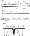
- FIG. 1 there is shown a wind turbine blade mould 2 according to a first embodiment of the present invention.
- the mould 2 is for moulding an entire wind turbine blade having a length of greater than 60 metres.
- the mould 2 includes a first section 4, including the blade root 6, a second central section 8 and a third tip section 10.
- the first and second sections 4, 8 are each less than 25 metres in length whereas the third tip section 10 is less than 11.8 metres in length.
- Each mould section 4, 6, 10 includes a respective frame section 12, 14, 16 and an associated respective moulding surface 18, 20, 22.
- Each frame section 12, 14, 16 is constructed of a welded steel structure, with the steel structure being provided with connecting mechanisms, such as bolts, for securely connecting the frame sections 12, 14, 16 together to form a unitary mould 2.
- Figure 11 shows, as an example, the mould section 6 carried on the frame section 14.
- the length of the sections was selected to facilitate shipping by land by trucks.
- the tip section 10 could be incorporated into a conventional shipping container.
- a wind turbine blade mould 32 according to a second embodiment of the present invention.
- the mould 32 is for moulding a spar cap of a wind turbine blade.
- the entire spar cap has a length of less than greater than 47.2 metres.
- the mould 32 includes four sections 34, 36, 38, 40, each less than 11.8 metres in length so that each section 34, 36, 38, 40 can be fitted into a conventional shipping container.
- Each mould section 34, 36, 38, 40 includes, as described above for the first embodiment, a respective frame section (not shown) and an associated respective moulding surface.
- the mould 42 is for moulding a shear web of a wind turbine blade.
- the entire shear web cap has a length of less than greater than 50 metres.
- the mould 42 includes four short sequentially adjacent sections 44, 46, 48, 50, to be located at the root end 52, each less than 2 metres in length so that each section 44, 46, 48, 50 can be fitted into a conventional shipping container.
- the mould 42 also includes four longer sections 54, 56, 58, 60, each less than 11.8 metres in length so that each section 54, 56, 58, 60 can be fitted into a conventional shipping container.
- Each mould section 44, 46, 48, 50, 54, 56, 58, 60 includes, as described above for the first embodiment, a respective frame section (not shown) and an associated respective moulding surface.
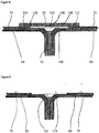
- FIG. 4 there is shown two mould sections of a wind turbine blade mould according to an embodiment of the present invention, the two sections abutting during an initial step of an assembly process for assembling a wind turbine blade mould.
- the mould 62 is for moulding a wind turbine blade or an elongate structural part thereof.
- the mould 62 comprises a plurality of longitudinal elongate mould sections 64, 66 fitted together in an end-to-end relationship to form a unitary mould, such as moulds 2, 32 or 42, or any other such mould. Only two such mould sections 64, 66 are shown, but more may be provided as shown in Figures 1 to 3 .
- the mould 62 comprises a plurality of assembly devices, such as bolts (not shown) for assembling together the mould sections 64, 66, for example by bolting together the frame sections as shown in Figure 1 , to form the unitary mould 62.
- the mould 62 further comprises an alignment device 63 fitted to each mould section 64, 66 for longitudinally aligning the mould sections 64, 66 to form the unitary mould 62.
- the alignment device 63 includes a guide element 65 including a notch or opening 67 for aligning a laser beam 69.
- Each mould section 64, 66 has a central mould portion 68 between opposite end portions 70.
- Each mould section 64, 66 is composed of a fibre reinforced resin matrix composite material 72 which forms the moulding surface 74, for example glass fibre reinforced epoxy resin.
- At least one end portion 70 of each mould section 64, 66 forms an integral flange 76 oriented substantially orthogonally downwardly with respect to the upper surface 78 of the mould section 64, 66.
- the upper surface 78 includes the moulding surface 74 and a recess 80 located between the flange 76 and the moulding surface 74.
- the recess 80 extends in a longitudinal direction and also across a transverse width of the mould section 64, 66 whereby when the flanges 76a, 76b of adjacent mould sections 64, 66 are fitted together in a substantially abutting relationship, with a vertical gap 81 therebetween, the adjacent recesses 80 form a combined recess 82 separating the moulding surfaces 74 of the adjacent mould sections 64, 66.
- the central mould portion 68 and the flange 76 are connected by a curved region 84 of the fibre reinforced resin matrix composite material 72.
- the curved region 84 forms a continuously curved upper surface 86 from the recess 80 to the flange 76.
- the mould further comprises heating wires 90 within each mould section 64, 66.
- the heating wires 90 extend from the central mould portion 68 into the flange 76 so as to provide substantially uniform heating across the surface area of the unitary moulding surface.
- the heating wires 4 are preferably located close to the moulding surface 74, for example the embedded wires being from 1mm to 20mm, typically from 2 to 10mm from the moulding surface 74.
- the unitary mould has a length of at least 50 metres and at least some of the mould sections have a length of at least 8 metres, and/or the maximum length of each mould section is less than 11.8 metres.
- a strap 120 of fibrous material for example of glass fibre impregnated with a curable resin such as epoxy resin, is laminated across a lower edge 122 of the adjacent flanges 76. This seals the lower edge of any gap between the flanges 76.
- a curable resin paste 92 for example including a curable epoxy resin and filler material such as silica particles to provide a high paste viscosity, is disposed in the vertical gap 81 between the flanges 76a, 76b of the two abutting sections 64, 66.
- the resin paste 92 includes metallic particles to provide a thermally conductive material between the adjacent flanges 76a, 76b and thereby increase the thermal conductivity of the connection between the flanges 76a, 76b.
- thermally conductive material enhances the uniformity of the thermal properties of the mould 62, so that even though the heating wires 90 are longitudinally spaced at the adjacent flanges 76a, 76b the presence of the thermally conductive material conducts heat from the heating wires toward the moulding surface above the cured resin paste, the curing being as discussed below, so as to compensate for the discontinuity of the heating wires at the connections between the mould sections.
- the delivery of heat to thermally cure the resin material of the wind blade during manufacture is substantially uniform over the surface area of the mould at the connections between the mould sections.
- the portion 94 of the combined recess 82 between the lower curved regions 84 above the resin paste 92 is filled with a first lamination of fibrous material 96 and curable resin 98.
- the fibrous material 96 is typically composed of glass fibres and the curable resin 98 is typically an epoxy resin.
- This first lamination acts provides a level upper surface and as a plug seal for a subsequent vacuum infusion process, as described below.
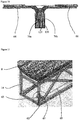
- the combined recess 82 between the upper portions of the two abutting sections 64, 66 is then completely filled with a second lamination 100 of fibrous material.
- Dry fibre mats 102 for example of glass fibre, are laid up into the combined recess 82, so as to level with the moulding surfaces 74.
- the mats 102 may comprise stitched or woven fabric.
- a mould tool 104 is located over the fibrous material 100 to define a mould cavity 105 containing the dry fibre lamination 100 having an upper surface 106 substantially aligned with the moulding surfaces 74 of the two abutting sections 64, 66.
- a curable resin 108 such as epoxy resin, is infused under vacuum into the fibrous material 100.
- the infusion point for the resin 108 is at the longitudinal centre of the combined recess 82, so that the resin 108 flows outwardly towards the longitudinal ends 110, 112 of the combined recess 82, and the infusion point may be located at the transverse centre or at a lateral side of the combined recess 82.
- the curable resins 98, 108 and in the resin paste 92 are then cured at elevated temperature and under vacuum to form a unitary fibre reinforced matrix resin material plug 111 intimately bonded to, and composed substantially of a similar fibre reinforced matrix resin composite material as, the mould sections 64, 66.
- the resultant plug 111 is shown in Figure 9 .
- the plug 111 has low surface roughness, which does not require finish sanding because the upper surface 114 of the plug 111 is defined by the mould tool 104, so that the two mould sections 64, 66 are assembled together with a substantially uniform interconnecting moulding surface 114 of the plug 111 substantially indistinguishable from the moulding surfaces 74 of the two mould sections 64, 66.
- the illustrated embodiment of the present invention employs a wind turbine blade mould
- the present invention may be implemented in moulds for moulding other large articles of composite material.
Landscapes
- Engineering & Computer Science (AREA)
- Mechanical Engineering (AREA)
- Manufacturing & Machinery (AREA)
- Chemical & Material Sciences (AREA)
- Composite Materials (AREA)
- Wind Motors (AREA)
- Moulds For Moulding Plastics Or The Like (AREA)
- Moulding By Coating Moulds (AREA)
Claims (14)
- Form (2, 32, 42, 62) zum Formen einer Windturbinenschaufel oder eines länglichen Strukturteils davon, wobei die Form mehrere längliche Formabschnitte in Längsrichtung (64, 66) aufweist, die in einer End-zu-End-Beziehung zusammengepasst sind, um eine einheitliche Form zu bilden, wobei jeder Formabschnitt (64, 66) einen zentralen Formabschnitt (68) zwischen gegenüberliegenden Endabschnitten (70) hat, wobei jeder Formabschnitt (64, 66) aus einem faserverstärkten Harzmatrixverbundmaterial (72) besteht, wobei wenigstens ein Endabschnitt (70) jedes Formabschnitts (64, 66) einen integralen Flansch (76) bildet, der in Bezug auf eine Oberseite (78) des Formabschnitts (64, 66) im Wesentlichen senkrecht nach unten ausgerichtet ist, und wobei die Oberseite (78) eine Formungsfläche (74) und eine zwischen dem Flansch (76) und der Formungsfläche (74) liegende Aussparung (80) enthält, wobei sich die Aussparung (80) über eine Querbreite des Formabschnitts (64, 66) erstreckt, wodurch die Flansche (76a, 76b) von benachbarten Formabschnitten (64, 66) in einer aneinandergrenzenden Beziehung zusammengepasst sind und die benachbarten Aussparungen (80) eine gemeinsame Aussparung (82) bilden, die die Formungsflächen (74) der benachbarten Formabschnitte (64, 66) trennt, dadurch gekennzeichnet, dass die Form ferner Heizdrähte (90) in jedem Formabschnitt (64, 66) aufweist, wobei sich die Heizdrähte (90) vom zentralen Formabschnitt (68) in den Flansch (76) erstrecken, ein vertikaler Spalt (81) zwischen aneinandergrenzenden Flanschen (76a, 76b) vorgesehen ist, und ein wärmeleitendes Material in dem vertikalen Spalt (81) angeordnet ist, wobei das wärmeleitende Material ein ausgehärtetes Harz (92) mit metallischen Partikeln aufweist, wobei die Heizdrähte (90) in den Flanschen (76a, 76b) angeordnet sind, um das wärmeleitende Material in dem vertikalen Spalt (81) zum Leiten von Wärme zur Formungsfläche (74) über dem wärmeleitenden Material während des Formens einer Windturbinenschaufel oder eines länglichen Strukturteils davon zu erwärmen.
- Form nach Anspruch 1, bei welcher die Heizdrähte ausgestaltet sind, um ein gleichmäßiges Erwärmen über einen Oberflächenbereich einer einheitlichen Formungsfläche zu schaffen, die gebildet ist, wenn die Flansche von benachbarten Formabschnitten in einer aneinandergrenzenden Beziehung zusammengepasst sind, um die gemeinsame Aussparung zu bilden.
- Form nach Anspruch 1 oder Anspruch 2, bei welcher die Heizdrähte in einem Abstand von 1 bis 20 mm, bevorzugt von 2 bis 10 mm, von der Formungsfläche des jeweiligen Formabschnitts eingebettet sind.
- Form nach einem der vorhergehenden Ansprüche, bei welcher der zentrale Formabschnitt und der Flansch durch einen gebogenen Bereich (84) des faserverstärkten Harzmatrixverbundmaterials verbunden sind, der eine kontinuierlich gebogene Oberseite (86) von der Aussparung zum Flansch bildet.
- Form nach einem der vorhergehenden Ansprüche, bei welcher das ausgehärtete Harz (92) Epoxidharz und Füllmaterial aufweist, wobei das Füllmaterial bevorzugt Siliciumdioxidpartikel aufweist.
- Form nach einem der vorhergehenden Ansprüche, bei welcher die einheitliche Form eine Länge von mindestens 50 Metern hat und wenigstens einige der Formabschnitte eine Länge von mindestens 8 Metern haben, wobei bevorzugt die einheitliche Form eine Länge von mindestens 50 Metern hat und die maximale Länge jedes Formabschnitts kleiner ist als 11,8 Meter.
- Verfahren zum Zusammenbauen einer Form (2, 32, 42, 62) zum Formen einer Windturbinenschaufel oder eines länglichen Strukturteils davon, wobei das Verfahren die Schritte aufweist:a. Bereitstellen von mehreren länglichen Formabschnitten in Längsrichtung (64, 66), die ausgestaltet sind, um in einer End-zu-End-Beziehung zusammengepasst zu werden, um eine einheitliche Form zu bilden, wobei jeder Formabschnitt (64, 66) einen zentralen Formabschnitt (68) zwischen gegenüberliegenden Endabschnitten (70) hat, wobei jeder Formabschnitt (64, 66) aus einem faserverstärkten Harzmatrixverbundmaterial (72) besteht, wobei wenigstens ein Endabschnitt jedes Formabschnitts (64, 66) einen integralen Flansch (76) bildet, der in Bezug auf eine Oberseite (78) des Formabschnitts (64, 66) im Wesentlichen senkrecht nach unten ausgerichtet ist, und von Heizdrähten (90) in jedem Formabschnitt (64, 66), wobei sich die Heizdrähte (90) vom zentralen Formabschnitt (68) in den Flansch (76) erstrecken, und wobei die Oberseite (78) eine Formungsfläche (74) und eine zwischen dem Flansch (76) und der Formungsfläche (74) liegende Aussparung (80) enthält, wobei sich die Aussparung (80) über eine Querbreite des Formabschnitts (64, 66) erstreckt;b. Zusammenpassen der Flansche (76a, 76b) von benachbarten Formabschnitten (64, 66) in einer aneinandergrenzenden Beziehung, wobei die benachbarten Aussparungen (80) eine gemeinsame Aussparung (82) bilden, die die Formungsflächen (74) der benachbarten Formabschnitte (64, 66) trennt, und Ablagern einer härtbaren Harzpaste (92) mit Metallpartikeln in einen vertikalen Spalt (81) zwischen den aneinandergrenzenden Flanschen (76a, 76b);c. Füllen der gemeinsamen Aussparung (82) mit einem Laminat aus Fasermaterial (100);d. Positionieren eines Formwerkzeugs (104) über dem Fasermaterial (100), um einen Formhohlraum (105) mit einer Oberseite (106), die im Wesentlichen auf die Formungsflächen (74) der benachbarten Formabschnitte (64, 66) ausgerichtet ist, zu definieren;e. Eingießen eines härtbaren Harzes (108) in das Fasermaterial (100); undf. Aushärten des Harzes (108), um ein faserverstärktes Harzmatrixverbundmaterial (111) zu bilden, das an die benachbarten Formabschnitte gebunden ist und dazwischen eine verbindende Formungsfläche (114) definiert, wobei die härtbare Harzpaste (92) während des Aushärtungsschritts f ausgehärtet wird, um ein wärmeleitendes Material zwischen den benachbarten Flanschen zu schaffen, wobei die Heizdrähte (90) in den Flanschen (76a, 76b) angeordnet werden, um das wärmeleitende Material im vertikalen Spalt (81) zum Leiten von Wärme zur Formungsfläche (74) über dem wärmeleitenden Material während des Formens einer Windturbinenschaufel oder eines länglichen Strukturteils davon zu erwärmen.
- Verfahren nach Anspruch 7, bei welchem die härtbare Harzpaste Epoxidharz und Füllmaterial aufweist, wobei das Füllmaterial bevorzugt Siliciumdioxidpartikel aufweist.
- Verfahren nach Anspruch 7 oder Anspruch 8, bei welchem die Heizdrähte ein gleichmäßiges Erwärmen über einen Oberflächenbereich einer einheitlichen Formungsfläche schaffen, die gebildet wird, wenn die Flansche von benachbarten Formabschnitten in einer aneinandergrenzenden Beziehung zusammengepasst werden, um die gemeinsame Aussparung zu bilden.
- Verfahren nach einem der Ansprüche 7 bis 9, bei welchem die Heizdrähte in einem Abstand von 1 bis 20 mm, bevorzugt von 2 bis 10 mm, von der Formungsfläche des jeweiligen Formabschnitts eingebettet werden.
- Verfahren nach einem der Ansprüche 7 bis 10, bei welchem der zentrale Formabschnitt und der Flansch durch einen gebogenen Bereich (84) des faserverstärkten Harzmatrixverbundmaterials verbunden werden, der eine kontinuierlich gebogene Oberseite (86) von der Aussparung zum Flansch bildet.
- Verfahren nach einem der Ansprüche 7 bis 11, ferner aufweisend vor dem Schritt e den Schritt eines Laminierens eines Bandes (120) aus Fasermaterial über einen unteren Rand der benachbarten Flansche.
- Verfahren nach einem der Ansprüche 7 bis 12, bei welchem die einheitliche Form eine Länge von mindestens 50 Metern hat und wenigstens einige der Formabschnitte eine Länge von mindestens 8 Metern haben, wobei bevorzugt die einheitliche Form eine Länge von mindestens 50 Metern hat und die maximale Länge jedes Formabschnitts kleiner ist als 11,8 Meter
- Verfahren zum Formen einer Windturbinenschaufel oder eines länglichen Strukturteils davon unter Verwendung der Form nach einem der Ansprüche 1 bis 6 oder einer durch das Verfahren nach einem der Ansprüche 7 bis 13 zusammengebauten Form.
Priority Applications (4)
| Application Number | Priority Date | Filing Date | Title |
|---|---|---|---|
| EP19194872.8A EP3608074B1 (de) | 2014-07-25 | 2014-07-25 | Form zum formen einer windturbinenschaufel und formanordnung |
| ES19194872T ES2864539T3 (es) | 2014-07-25 | 2014-07-25 | Molde para moldear una pala de turbina eólica y conjunto de molde |
| PL19194872T PL3608074T3 (pl) | 2014-07-25 | 2014-07-25 | Forma do formowania łopaty turbiny wiatrowej i montaż formy |
| DK19194872.8T DK3608074T3 (da) | 2014-07-25 | 2014-07-25 | Form til formning af en vindmøllevinge og formenhed |
Applications Claiming Priority (3)
| Application Number | Priority Date | Filing Date | Title |
|---|---|---|---|
| EP19194872.8A EP3608074B1 (de) | 2014-07-25 | 2014-07-25 | Form zum formen einer windturbinenschaufel und formanordnung |
| EP14898037.8A EP3172022B1 (de) | 2014-07-25 | 2014-07-25 | Form zum formen einer windturbinenschaufel und formanordnung |
| PCT/CN2014/082996 WO2016011655A1 (en) | 2014-07-25 | 2014-07-25 | Mould for moulding wind turbine blade and assembly of mould |
Related Parent Applications (2)
| Application Number | Title | Priority Date | Filing Date |
|---|---|---|---|
| EP14898037.8A Division EP3172022B1 (de) | 2014-07-25 | 2014-07-25 | Form zum formen einer windturbinenschaufel und formanordnung |
| EP14898037.8A Division-Into EP3172022B1 (de) | 2014-07-25 | 2014-07-25 | Form zum formen einer windturbinenschaufel und formanordnung |
Publications (2)
| Publication Number | Publication Date |
|---|---|
| EP3608074A1 EP3608074A1 (de) | 2020-02-12 |
| EP3608074B1 true EP3608074B1 (de) | 2021-03-24 |
Family
ID=55162452
Family Applications (2)
| Application Number | Title | Priority Date | Filing Date |
|---|---|---|---|
| EP14898037.8A Active EP3172022B1 (de) | 2014-07-25 | 2014-07-25 | Form zum formen einer windturbinenschaufel und formanordnung |
| EP19194872.8A Active EP3608074B1 (de) | 2014-07-25 | 2014-07-25 | Form zum formen einer windturbinenschaufel und formanordnung |
Family Applications Before (1)
| Application Number | Title | Priority Date | Filing Date |
|---|---|---|---|
| EP14898037.8A Active EP3172022B1 (de) | 2014-07-25 | 2014-07-25 | Form zum formen einer windturbinenschaufel und formanordnung |
Country Status (7)
| Country | Link |
|---|---|
| US (1) | US10668648B2 (de) |
| EP (2) | EP3172022B1 (de) |
| BR (1) | BR112017001494A2 (de) |
| DK (2) | DK3608074T3 (de) |
| ES (2) | ES2759531T3 (de) |
| PL (2) | PL3608074T3 (de) |
| WO (1) | WO2016011655A1 (de) |
Families Citing this family (13)
| Publication number | Priority date | Publication date | Assignee | Title |
|---|---|---|---|---|
| US20170036375A1 (en) | 2015-08-07 | 2017-02-09 | Hexcel Corporation | Multi-sectional composite tooling |
| CA2942019C (en) | 2015-09-14 | 2018-09-25 | Bell Helicopter Textron Inc. | Modular tooling for manufacturing multi-cavity composite structures |
| US20180104863A1 (en) * | 2016-10-19 | 2018-04-19 | Aurora Flight Sciences Corporation | Increased Utility Composite Tooling through Additive Manufacturing |
| US20180345604A1 (en) | 2017-06-02 | 2018-12-06 | Arris Composites Llc | Aligned fiber reinforced molding |
| US11123900B2 (en) * | 2017-09-20 | 2021-09-21 | Bell Helicopter Textron Inc. | Mold tool with anisotropic thermal properties |
| CN108556213B (zh) * | 2017-12-22 | 2024-01-30 | 固瑞特模具(太仓)有限公司 | 风电阴模型面分段加固结构 |
| WO2019149885A1 (en) * | 2018-02-01 | 2019-08-08 | Lm Wind Power International Technology Ii Aps | Connection of mould parts |
| WO2019182634A1 (en) * | 2018-03-21 | 2019-09-26 | Tpi Composites, Inc. | Mold with thermally conductive flanges |
| WO2020077272A1 (en) * | 2018-10-12 | 2020-04-16 | Arris Composites Inc. | Preform charges and fixtures therefor |
| MA55072A (fr) | 2019-02-28 | 2022-01-05 | Lm Wind Power As | Moule de préforme souple permettant la fabrication d'une préforme destinée à une pale d'éolienne |
| EP3715080A1 (de) | 2019-03-26 | 2020-09-30 | Siemens Gamesa Renewable Energy A/S | Modulare formvorrichtung, formsystem und verfahren zur erzeugung einer form für ein schaufelsegment einer windturbinenschaufel einer windturbine |
| CN110733148B (zh) * | 2019-10-17 | 2021-07-30 | 明阳智慧能源集团股份公司 | 一种风电叶片腹板模具粘接挡边的安装方法 |
| CN116619634A (zh) * | 2023-05-26 | 2023-08-22 | 固瑞特模具(太仓)有限公司 | 一种超大型风电阴模根部加固方法 |
Family Cites Families (21)
| Publication number | Priority date | Publication date | Assignee | Title |
|---|---|---|---|---|
| US4976587A (en) * | 1988-07-20 | 1990-12-11 | Dwr Wind Technologies Inc. | Composite wind turbine rotor blade and method for making same |
| US5449282A (en) * | 1991-10-10 | 1995-09-12 | Gencorp Inc. | Self-centering molding apparatus |
| CA2160644C (en) * | 1995-10-16 | 2005-05-24 | Jobst Ulrich Gellert | Cooled thread split inserts for injection molding preforms |
| WO2009007077A1 (en) * | 2007-07-06 | 2009-01-15 | Éire Composites Teoranta | An integrally heated mould |
| DE102008038620A1 (de) * | 2008-06-27 | 2009-12-31 | Powerblades Gmbh | Verfahren und Fertigungsform zur Fertigung eines Rotorblattes für eine Windenergieanlage |
| CN201432382Y (zh) * | 2009-02-24 | 2010-03-31 | 刘汝斌 | 一种风力发电机叶片模具 |
| CN201357535Y (zh) * | 2009-03-13 | 2009-12-09 | 苏州红枫风电模具有限公司 | 用于大型组合式模具的可调整的对齐装置 |
| DE102009033164A1 (de) * | 2009-07-13 | 2011-01-27 | Repower Systems Ag | Rotorblatt einer Windenergieanlage sowie Verfahren zum Fertigen eines Rotorblattes einer Windenergieanlage |
| CN102019651A (zh) * | 2009-09-11 | 2011-04-20 | 苏州红枫风电模具有限公司 | 风轮机叶片模具加热系统 |
| ES2396952T3 (es) * | 2010-02-15 | 2013-03-01 | Siemens Aktiengesellschaft | Molde, aparato y método para fabricar una pieza compuesta que incluye al menos una matriz reforzada con fibras |
| US20130113141A1 (en) * | 2010-03-19 | 2013-05-09 | Ssp Technology A/S | Heated mould and a method for forming fibre reinforced composites |
| IN2014DN05956A (de) * | 2011-12-30 | 2015-06-26 | Vestas Wind Sys As | |
| DK177679B1 (en) * | 2012-10-03 | 2014-02-24 | Dencam Composite As | Segmented Plug Device |
| WO2014166493A1 (en) * | 2013-04-08 | 2014-10-16 | Vestas Wind Systems A/S | A fibre preform for laying on a curved surface of a mould |
| DK3027892T3 (en) * | 2013-08-02 | 2017-07-24 | Vestas Wind Sys As | Blade for a wind turbine and a method for making a blade for a wind turbine |
| ES2773673T3 (es) * | 2014-08-19 | 2020-07-14 | Lm Wp Patent Holding As | Un método de fabricación de un molde para una estructura de pala de aerogenerador |
| EP3380313B1 (de) * | 2015-11-26 | 2019-08-07 | Vestas Wind Systems A/S | Verbesserung im zusammenhang mit der herstellung von windturbinenschaufeln |
| CN108700028B (zh) * | 2015-12-23 | 2021-08-24 | Lm Wp 专利控股有限公司 | 风力涡轮机叶片及相关制造方法 |
| DE102016008125A1 (de) * | 2016-07-05 | 2018-01-11 | Senvion Gmbh | Herstellungsform eines Rotorblattes |
| WO2018091054A1 (en) * | 2016-11-17 | 2018-05-24 | Vestas Wind Systems A/S | A reinforcing structure for a wind turbine blade |
| WO2019182634A1 (en) * | 2018-03-21 | 2019-09-26 | Tpi Composites, Inc. | Mold with thermally conductive flanges |
-
2014
- 2014-07-25 PL PL19194872T patent/PL3608074T3/pl unknown
- 2014-07-25 EP EP14898037.8A patent/EP3172022B1/de active Active
- 2014-07-25 US US15/326,861 patent/US10668648B2/en active Active
- 2014-07-25 DK DK19194872.8T patent/DK3608074T3/da active
- 2014-07-25 EP EP19194872.8A patent/EP3608074B1/de active Active
- 2014-07-25 ES ES14898037T patent/ES2759531T3/es active Active
- 2014-07-25 ES ES19194872T patent/ES2864539T3/es active Active
- 2014-07-25 DK DK14898037.8T patent/DK3172022T3/da active
- 2014-07-25 BR BR112017001494A patent/BR112017001494A2/pt not_active Application Discontinuation
- 2014-07-25 WO PCT/CN2014/082996 patent/WO2016011655A1/en not_active Ceased
- 2014-07-25 PL PL14898037T patent/PL3172022T3/pl unknown
Non-Patent Citations (1)
| Title |
|---|
| None * |
Also Published As
| Publication number | Publication date |
|---|---|
| EP3172022A4 (de) | 2018-03-21 |
| BR112017001494A2 (pt) | 2017-12-05 |
| PL3172022T3 (pl) | 2020-11-02 |
| WO2016011655A1 (en) | 2016-01-28 |
| DK3608074T3 (da) | 2021-05-10 |
| DK3172022T3 (da) | 2020-01-27 |
| US10668648B2 (en) | 2020-06-02 |
| EP3172022B1 (de) | 2019-10-23 |
| US20170210035A1 (en) | 2017-07-27 |
| EP3608074A1 (de) | 2020-02-12 |
| ES2759531T3 (es) | 2020-05-11 |
| ES2864539T3 (es) | 2021-10-14 |
| EP3172022A1 (de) | 2017-05-31 |
| PL3608074T3 (pl) | 2021-09-27 |
Similar Documents
| Publication | Publication Date | Title |
|---|---|---|
| EP3608074B1 (de) | Form zum formen einer windturbinenschaufel und formanordnung | |
| US11752709B2 (en) | Reinforcing structure for a wind turbine blade | |
| ES2674663T3 (es) | Un método para fabricar una parte de cubierta aerodinámica para una pala de turbina eólica | |
| US20180156202A1 (en) | Spar cap assembly for a wind turbine rotor blade | |
| ES2909421T3 (es) | Miembro estructural aeroespacial con estructura compuesta híbrida | |
| US20190353143A1 (en) | Method of manufacturing a spar cap | |
| US9394881B2 (en) | Wind turbine blade and method of fabricating a wind turbine blade | |
| CN106457719B (zh) | 具有改进的纤维过渡的风力涡轮机叶片 | |
| US20150023799A1 (en) | Structural Member with Pultrusions | |
| CN114450147B (zh) | 制造风力涡轮机叶片的结构元件的方法、制造风力涡轮机叶片的方法、风力涡轮机叶片的结构元件和风力涡轮机叶片 | |
| CN106457696A (zh) | 以两个步骤制造的风力涡轮机叶片部件 | |
| WO2011113812A1 (en) | Improved wind turbine blade spar | |
| EP3027892B1 (de) | Schaufel für eine windturbine und verfahren zur herstellung einer schaufel für eine windturbine | |
| EP3658767B1 (de) | Bahnfuss für eine scherbahn | |
| CN113757036B (zh) | 一种改进后缘结构的风电叶片及其制作方法 | |
| US11066939B2 (en) | Composite blade and method for producing composite blade | |
| EP3894190B1 (de) | Verfahren zur herstellung eines scherstegflanschteils eines windturbinenschaufels und eines scherstegs eines windturbinenschaufels. | |
| CN109318506A (zh) | 一种复合材料网架式点阵结构及制备方法 | |
| US11761422B2 (en) | Relating to wind turbine blade manufacture | |
| CN120867942A (zh) | 叶根模块、叶根及其成型方法、风电叶片 |
Legal Events
| Date | Code | Title | Description |
|---|---|---|---|
| PUAI | Public reference made under article 153(3) epc to a published international application that has entered the european phase |
Free format text: ORIGINAL CODE: 0009012 |
|
| STAA | Information on the status of an ep patent application or granted ep patent |
Free format text: STATUS: THE APPLICATION HAS BEEN PUBLISHED |
|
| AC | Divisional application: reference to earlier application |
Ref document number: 3172022 Country of ref document: EP Kind code of ref document: P |
|
| AK | Designated contracting states |
Kind code of ref document: A1 Designated state(s): AL AT BE BG CH CY CZ DE DK EE ES FI FR GB GR HR HU IE IS IT LI LT LU LV MC MK MT NL NO PL PT RO RS SE SI SK SM TR |
|
| STAA | Information on the status of an ep patent application or granted ep patent |
Free format text: STATUS: REQUEST FOR EXAMINATION WAS MADE |
|
| 17P | Request for examination filed |
Effective date: 20200511 |
|
| RBV | Designated contracting states (corrected) |
Designated state(s): AL AT BE BG CH CY CZ DE DK EE ES FI FR GB GR HR HU IE IS IT LI LT LU LV MC MK MT NL NO PL PT RO RS SE SI SK SM TR |
|
| GRAP | Despatch of communication of intention to grant a patent |
Free format text: ORIGINAL CODE: EPIDOSNIGR1 |
|
| STAA | Information on the status of an ep patent application or granted ep patent |
Free format text: STATUS: GRANT OF PATENT IS INTENDED |
|
| RIC1 | Information provided on ipc code assigned before grant |
Ipc: B29C 33/40 20060101ALI20201105BHEP Ipc: B29L 31/08 20060101ALN20201105BHEP Ipc: B29C 33/30 20060101AFI20201105BHEP |
|
| INTG | Intention to grant announced |
Effective date: 20201209 |
|
| RIC1 | Information provided on ipc code assigned before grant |
Ipc: B29C 33/40 20060101ALI20201127BHEP Ipc: B29L 31/08 20060101ALN20201127BHEP Ipc: B29C 33/30 20060101AFI20201127BHEP |
|
| GRAS | Grant fee paid |
Free format text: ORIGINAL CODE: EPIDOSNIGR3 |
|
| GRAA | (expected) grant |
Free format text: ORIGINAL CODE: 0009210 |
|
| STAA | Information on the status of an ep patent application or granted ep patent |
Free format text: STATUS: THE PATENT HAS BEEN GRANTED |
|
| AC | Divisional application: reference to earlier application |
Ref document number: 3172022 Country of ref document: EP Kind code of ref document: P |
|
| AK | Designated contracting states |
Kind code of ref document: B1 Designated state(s): AL AT BE BG CH CY CZ DE DK EE ES FI FR GB GR HR HU IE IS IT LI LT LU LV MC MK MT NL NO PL PT RO RS SE SI SK SM TR |
|
| REG | Reference to a national code |
Ref country code: GB Ref legal event code: FG4D |
|
| REG | Reference to a national code |
Ref country code: CH Ref legal event code: EP |
|
| REG | Reference to a national code |
Ref country code: DE Ref legal event code: R096 Ref document number: 602014076090 Country of ref document: DE |
|
| REG | Reference to a national code |
Ref country code: IE Ref legal event code: FG4D |
|
| REG | Reference to a national code |
Ref country code: AT Ref legal event code: REF Ref document number: 1374035 Country of ref document: AT Kind code of ref document: T Effective date: 20210415 |
|
| REG | Reference to a national code |
Ref country code: DK Ref legal event code: T3 Effective date: 20210504 |
|
| REG | Reference to a national code |
Ref country code: LT Ref legal event code: MG9D |
|
| PG25 | Lapsed in a contracting state [announced via postgrant information from national office to epo] |
Ref country code: FI Free format text: LAPSE BECAUSE OF FAILURE TO SUBMIT A TRANSLATION OF THE DESCRIPTION OR TO PAY THE FEE WITHIN THE PRESCRIBED TIME-LIMIT Effective date: 20210324 Ref country code: GR Free format text: LAPSE BECAUSE OF FAILURE TO SUBMIT A TRANSLATION OF THE DESCRIPTION OR TO PAY THE FEE WITHIN THE PRESCRIBED TIME-LIMIT Effective date: 20210625 Ref country code: HR Free format text: LAPSE BECAUSE OF FAILURE TO SUBMIT A TRANSLATION OF THE DESCRIPTION OR TO PAY THE FEE WITHIN THE PRESCRIBED TIME-LIMIT Effective date: 20210324 Ref country code: BG Free format text: LAPSE BECAUSE OF FAILURE TO SUBMIT A TRANSLATION OF THE DESCRIPTION OR TO PAY THE FEE WITHIN THE PRESCRIBED TIME-LIMIT Effective date: 20210624 Ref country code: NO Free format text: LAPSE BECAUSE OF FAILURE TO SUBMIT A TRANSLATION OF THE DESCRIPTION OR TO PAY THE FEE WITHIN THE PRESCRIBED TIME-LIMIT Effective date: 20210624 |
|
| PG25 | Lapsed in a contracting state [announced via postgrant information from national office to epo] |
Ref country code: LV Free format text: LAPSE BECAUSE OF FAILURE TO SUBMIT A TRANSLATION OF THE DESCRIPTION OR TO PAY THE FEE WITHIN THE PRESCRIBED TIME-LIMIT Effective date: 20210324 Ref country code: RS Free format text: LAPSE BECAUSE OF FAILURE TO SUBMIT A TRANSLATION OF THE DESCRIPTION OR TO PAY THE FEE WITHIN THE PRESCRIBED TIME-LIMIT Effective date: 20210324 Ref country code: SE Free format text: LAPSE BECAUSE OF FAILURE TO SUBMIT A TRANSLATION OF THE DESCRIPTION OR TO PAY THE FEE WITHIN THE PRESCRIBED TIME-LIMIT Effective date: 20210324 |
|
| REG | Reference to a national code |
Ref country code: NL Ref legal event code: MP Effective date: 20210324 |
|
| REG | Reference to a national code |
Ref country code: AT Ref legal event code: MK05 Ref document number: 1374035 Country of ref document: AT Kind code of ref document: T Effective date: 20210324 |
|
| PG25 | Lapsed in a contracting state [announced via postgrant information from national office to epo] |
Ref country code: NL Free format text: LAPSE BECAUSE OF FAILURE TO SUBMIT A TRANSLATION OF THE DESCRIPTION OR TO PAY THE FEE WITHIN THE PRESCRIBED TIME-LIMIT Effective date: 20210324 |
|
| REG | Reference to a national code |
Ref country code: ES Ref legal event code: FG2A Ref document number: 2864539 Country of ref document: ES Kind code of ref document: T3 Effective date: 20211014 |
|
| PG25 | Lapsed in a contracting state [announced via postgrant information from national office to epo] |
Ref country code: LT Free format text: LAPSE BECAUSE OF FAILURE TO SUBMIT A TRANSLATION OF THE DESCRIPTION OR TO PAY THE FEE WITHIN THE PRESCRIBED TIME-LIMIT Effective date: 20210324 Ref country code: CZ Free format text: LAPSE BECAUSE OF FAILURE TO SUBMIT A TRANSLATION OF THE DESCRIPTION OR TO PAY THE FEE WITHIN THE PRESCRIBED TIME-LIMIT Effective date: 20210324 Ref country code: EE Free format text: LAPSE BECAUSE OF FAILURE TO SUBMIT A TRANSLATION OF THE DESCRIPTION OR TO PAY THE FEE WITHIN THE PRESCRIBED TIME-LIMIT Effective date: 20210324 Ref country code: SM Free format text: LAPSE BECAUSE OF FAILURE TO SUBMIT A TRANSLATION OF THE DESCRIPTION OR TO PAY THE FEE WITHIN THE PRESCRIBED TIME-LIMIT Effective date: 20210324 Ref country code: AT Free format text: LAPSE BECAUSE OF FAILURE TO SUBMIT A TRANSLATION OF THE DESCRIPTION OR TO PAY THE FEE WITHIN THE PRESCRIBED TIME-LIMIT Effective date: 20210324 |
|
| PG25 | Lapsed in a contracting state [announced via postgrant information from national office to epo] |
Ref country code: RO Free format text: LAPSE BECAUSE OF FAILURE TO SUBMIT A TRANSLATION OF THE DESCRIPTION OR TO PAY THE FEE WITHIN THE PRESCRIBED TIME-LIMIT Effective date: 20210324 Ref country code: PT Free format text: LAPSE BECAUSE OF FAILURE TO SUBMIT A TRANSLATION OF THE DESCRIPTION OR TO PAY THE FEE WITHIN THE PRESCRIBED TIME-LIMIT Effective date: 20210726 Ref country code: SK Free format text: LAPSE BECAUSE OF FAILURE TO SUBMIT A TRANSLATION OF THE DESCRIPTION OR TO PAY THE FEE WITHIN THE PRESCRIBED TIME-LIMIT Effective date: 20210324 Ref country code: IS Free format text: LAPSE BECAUSE OF FAILURE TO SUBMIT A TRANSLATION OF THE DESCRIPTION OR TO PAY THE FEE WITHIN THE PRESCRIBED TIME-LIMIT Effective date: 20210724 |
|
| PGFP | Annual fee paid to national office [announced via postgrant information from national office to epo] |
Ref country code: DE Payment date: 20210630 Year of fee payment: 8 |
|
| REG | Reference to a national code |
Ref country code: DE Ref legal event code: R097 Ref document number: 602014076090 Country of ref document: DE |
|
| PG25 | Lapsed in a contracting state [announced via postgrant information from national office to epo] |
Ref country code: AL Free format text: LAPSE BECAUSE OF FAILURE TO SUBMIT A TRANSLATION OF THE DESCRIPTION OR TO PAY THE FEE WITHIN THE PRESCRIBED TIME-LIMIT Effective date: 20210324 |
|
| PLBE | No opposition filed within time limit |
Free format text: ORIGINAL CODE: 0009261 |
|
| STAA | Information on the status of an ep patent application or granted ep patent |
Free format text: STATUS: NO OPPOSITION FILED WITHIN TIME LIMIT |
|
| PG25 | Lapsed in a contracting state [announced via postgrant information from national office to epo] |
Ref country code: SI Free format text: LAPSE BECAUSE OF FAILURE TO SUBMIT A TRANSLATION OF THE DESCRIPTION OR TO PAY THE FEE WITHIN THE PRESCRIBED TIME-LIMIT Effective date: 20210324 |
|
| REG | Reference to a national code |
Ref country code: CH Ref legal event code: PL |
|
| 26N | No opposition filed |
Effective date: 20220104 |
|
| GBPC | Gb: european patent ceased through non-payment of renewal fee |
Effective date: 20210725 |
|
| PG25 | Lapsed in a contracting state [announced via postgrant information from national office to epo] |
Ref country code: MC Free format text: LAPSE BECAUSE OF FAILURE TO SUBMIT A TRANSLATION OF THE DESCRIPTION OR TO PAY THE FEE WITHIN THE PRESCRIBED TIME-LIMIT Effective date: 20210324 |
|
| REG | Reference to a national code |
Ref country code: BE Ref legal event code: MM Effective date: 20210731 |
|
| PG25 | Lapsed in a contracting state [announced via postgrant information from national office to epo] |
Ref country code: LI Free format text: LAPSE BECAUSE OF NON-PAYMENT OF DUE FEES Effective date: 20210731 Ref country code: GB Free format text: LAPSE BECAUSE OF NON-PAYMENT OF DUE FEES Effective date: 20210725 Ref country code: CH Free format text: LAPSE BECAUSE OF NON-PAYMENT OF DUE FEES Effective date: 20210731 |
|
| PG25 | Lapsed in a contracting state [announced via postgrant information from national office to epo] |
Ref country code: IS Free format text: LAPSE BECAUSE OF FAILURE TO SUBMIT A TRANSLATION OF THE DESCRIPTION OR TO PAY THE FEE WITHIN THE PRESCRIBED TIME-LIMIT Effective date: 20210724 Ref country code: LU Free format text: LAPSE BECAUSE OF NON-PAYMENT OF DUE FEES Effective date: 20210725 Ref country code: FR Free format text: LAPSE BECAUSE OF NON-PAYMENT OF DUE FEES Effective date: 20210731 |
|
| PG25 | Lapsed in a contracting state [announced via postgrant information from national office to epo] |
Ref country code: IE Free format text: LAPSE BECAUSE OF NON-PAYMENT OF DUE FEES Effective date: 20210725 Ref country code: BE Free format text: LAPSE BECAUSE OF NON-PAYMENT OF DUE FEES Effective date: 20210731 |
|
| PG25 | Lapsed in a contracting state [announced via postgrant information from national office to epo] |
Ref country code: IT Free format text: LAPSE BECAUSE OF FAILURE TO SUBMIT A TRANSLATION OF THE DESCRIPTION OR TO PAY THE FEE WITHIN THE PRESCRIBED TIME-LIMIT Effective date: 20210324 |
|
| REG | Reference to a national code |
Ref country code: DE Ref legal event code: R119 Ref document number: 602014076090 Country of ref document: DE |
|
| PG25 | Lapsed in a contracting state [announced via postgrant information from national office to epo] |
Ref country code: DE Free format text: LAPSE BECAUSE OF NON-PAYMENT OF DUE FEES Effective date: 20230201 |
|
| PG25 | Lapsed in a contracting state [announced via postgrant information from national office to epo] |
Ref country code: CY Free format text: LAPSE BECAUSE OF FAILURE TO SUBMIT A TRANSLATION OF THE DESCRIPTION OR TO PAY THE FEE WITHIN THE PRESCRIBED TIME-LIMIT Effective date: 20210324 |
|
| PG25 | Lapsed in a contracting state [announced via postgrant information from national office to epo] |
Ref country code: HU Free format text: LAPSE BECAUSE OF FAILURE TO SUBMIT A TRANSLATION OF THE DESCRIPTION OR TO PAY THE FEE WITHIN THE PRESCRIBED TIME-LIMIT; INVALID AB INITIO Effective date: 20140725 |
|
| PG25 | Lapsed in a contracting state [announced via postgrant information from national office to epo] |
Ref country code: MK Free format text: LAPSE BECAUSE OF FAILURE TO SUBMIT A TRANSLATION OF THE DESCRIPTION OR TO PAY THE FEE WITHIN THE PRESCRIBED TIME-LIMIT Effective date: 20210324 |
|
| PG25 | Lapsed in a contracting state [announced via postgrant information from national office to epo] |
Ref country code: PL Free format text: LAPSE BECAUSE OF NON-PAYMENT OF DUE FEES Effective date: 20210725 |
|
| PG25 | Lapsed in a contracting state [announced via postgrant information from national office to epo] |
Ref country code: TR Free format text: LAPSE BECAUSE OF FAILURE TO SUBMIT A TRANSLATION OF THE DESCRIPTION OR TO PAY THE FEE WITHIN THE PRESCRIBED TIME-LIMIT Effective date: 20210324 |
|
| PG25 | Lapsed in a contracting state [announced via postgrant information from national office to epo] |
Ref country code: MT Free format text: LAPSE BECAUSE OF FAILURE TO SUBMIT A TRANSLATION OF THE DESCRIPTION OR TO PAY THE FEE WITHIN THE PRESCRIBED TIME-LIMIT Effective date: 20210324 |
|
| PGFP | Annual fee paid to national office [announced via postgrant information from national office to epo] |
Ref country code: DK Payment date: 20250623 Year of fee payment: 12 |
|
| PGFP | Annual fee paid to national office [announced via postgrant information from national office to epo] |
Ref country code: ES Payment date: 20250801 Year of fee payment: 12 |