EP3608073A2 - Fuel container and power work equipment - Google Patents
Fuel container and power work equipment Download PDFInfo
- Publication number
- EP3608073A2 EP3608073A2 EP19191124.7A EP19191124A EP3608073A2 EP 3608073 A2 EP3608073 A2 EP 3608073A2 EP 19191124 A EP19191124 A EP 19191124A EP 3608073 A2 EP3608073 A2 EP 3608073A2
- Authority
- EP
- European Patent Office
- Prior art keywords
- bag
- fuel
- work equipment
- internal combustion
- combustion engine
- Prior art date
- Legal status (The legal status is an assumption and is not a legal conclusion. Google has not performed a legal analysis and makes no representation as to the accuracy of the status listed.)
- Withdrawn
Links
Images


Classifications
-
- F—MECHANICAL ENGINEERING; LIGHTING; HEATING; WEAPONS; BLASTING
- F02—COMBUSTION ENGINES; HOT-GAS OR COMBUSTION-PRODUCT ENGINE PLANTS
- F02M—SUPPLYING COMBUSTION ENGINES IN GENERAL WITH COMBUSTIBLE MIXTURES OR CONSTITUENTS THEREOF
- F02M37/00—Apparatus or systems for feeding liquid fuel from storage containers to carburettors or fuel-injection apparatus; Arrangements for purifying liquid fuel specially adapted for, or arranged on, internal-combustion engines
- F02M37/0047—Layout or arrangement of systems for feeding fuel
- F02M37/007—Layout or arrangement of systems for feeding fuel characterised by its use in vehicles, in stationary plants or in small engines, e.g. hand held tools
-
- B—PERFORMING OPERATIONS; TRANSPORTING
- B27—WORKING OR PRESERVING WOOD OR SIMILAR MATERIAL; NAILING OR STAPLING MACHINES IN GENERAL
- B27B—SAWS FOR WOOD OR SIMILAR MATERIAL; COMPONENTS OR ACCESSORIES THEREFOR
- B27B17/00—Chain saws; Equipment therefor
- B27B17/12—Lubricating devices specially designed for chain saws
-
- B—PERFORMING OPERATIONS; TRANSPORTING
- B27—WORKING OR PRESERVING WOOD OR SIMILAR MATERIAL; NAILING OR STAPLING MACHINES IN GENERAL
- B27B—SAWS FOR WOOD OR SIMILAR MATERIAL; COMPONENTS OR ACCESSORIES THEREFOR
- B27B17/00—Chain saws; Equipment therefor
-
- B—PERFORMING OPERATIONS; TRANSPORTING
- B65—CONVEYING; PACKING; STORING; HANDLING THIN OR FILAMENTARY MATERIAL
- B65D—CONTAINERS FOR STORAGE OR TRANSPORT OF ARTICLES OR MATERIALS, e.g. BAGS, BARRELS, BOTTLES, BOXES, CANS, CARTONS, CRATES, DRUMS, JARS, TANKS, HOPPERS, FORWARDING CONTAINERS; ACCESSORIES, CLOSURES, OR FITTINGS THEREFOR; PACKAGING ELEMENTS; PACKAGES
- B65D35/00—Pliable tubular containers adapted to be permanently or temporarily deformed to expel contents, e.g. collapsible tubes for toothpaste or other plastic or semi-liquid material; Holders therefor
- B65D35/02—Body construction
- B65D35/04—Body construction made in one piece
- B65D35/06—Body construction made in one piece from metallic material
-
- B—PERFORMING OPERATIONS; TRANSPORTING
- B65—CONVEYING; PACKING; STORING; HANDLING THIN OR FILAMENTARY MATERIAL
- B65D—CONTAINERS FOR STORAGE OR TRANSPORT OF ARTICLES OR MATERIALS, e.g. BAGS, BARRELS, BOTTLES, BOXES, CANS, CARTONS, CRATES, DRUMS, JARS, TANKS, HOPPERS, FORWARDING CONTAINERS; ACCESSORIES, CLOSURES, OR FITTINGS THEREFOR; PACKAGING ELEMENTS; PACKAGES
- B65D35/00—Pliable tubular containers adapted to be permanently or temporarily deformed to expel contents, e.g. collapsible tubes for toothpaste or other plastic or semi-liquid material; Holders therefor
- B65D35/02—Body construction
- B65D35/04—Body construction made in one piece
- B65D35/08—Body construction made in one piece from plastics material
-
- F—MECHANICAL ENGINEERING; LIGHTING; HEATING; WEAPONS; BLASTING
- F01—MACHINES OR ENGINES IN GENERAL; ENGINE PLANTS IN GENERAL; STEAM ENGINES
- F01M—LUBRICATING OF MACHINES OR ENGINES IN GENERAL; LUBRICATING INTERNAL COMBUSTION ENGINES; CRANKCASE VENTILATING
- F01M3/00—Lubrication specially adapted for engines with crankcase compression of fuel-air mixture or for other engines in which lubricant is contained in fuel, combustion air, or fuel-air mixture
-
- F—MECHANICAL ENGINEERING; LIGHTING; HEATING; WEAPONS; BLASTING
- F02—COMBUSTION ENGINES; HOT-GAS OR COMBUSTION-PRODUCT ENGINE PLANTS
- F02B—INTERNAL-COMBUSTION PISTON ENGINES; COMBUSTION ENGINES IN GENERAL
- F02B63/00—Adaptations of engines for driving pumps, hand-held tools or electric generators; Portable combinations of engines with engine-driven devices
- F02B63/02—Adaptations of engines for driving pumps, hand-held tools or electric generators; Portable combinations of engines with engine-driven devices for hand-held tools
-
- F—MECHANICAL ENGINEERING; LIGHTING; HEATING; WEAPONS; BLASTING
- F02—COMBUSTION ENGINES; HOT-GAS OR COMBUSTION-PRODUCT ENGINE PLANTS
- F02M—SUPPLYING COMBUSTION ENGINES IN GENERAL WITH COMBUSTIBLE MIXTURES OR CONSTITUENTS THEREOF
- F02M17/00—Carburettors having pertinent characteristics not provided for in, or of interest apart from, the apparatus of preceding main groups F02M1/00 - F02M15/00
- F02M17/02—Floatless carburettors
- F02M17/04—Floatless carburettors having fuel inlet valve controlled by diaphragm
-
- F—MECHANICAL ENGINEERING; LIGHTING; HEATING; WEAPONS; BLASTING
- F02—COMBUSTION ENGINES; HOT-GAS OR COMBUSTION-PRODUCT ENGINE PLANTS
- F02M—SUPPLYING COMBUSTION ENGINES IN GENERAL WITH COMBUSTIBLE MIXTURES OR CONSTITUENTS THEREOF
- F02M19/00—Details, component parts, or accessories of carburettors, not provided for in, or of interest apart from, the apparatus of groups F02M1/00 - F02M17/00
- F02M19/06—Other details of fuel conduits
-
- F—MECHANICAL ENGINEERING; LIGHTING; HEATING; WEAPONS; BLASTING
- F02—COMBUSTION ENGINES; HOT-GAS OR COMBUSTION-PRODUCT ENGINE PLANTS
- F02M—SUPPLYING COMBUSTION ENGINES IN GENERAL WITH COMBUSTIBLE MIXTURES OR CONSTITUENTS THEREOF
- F02M37/00—Apparatus or systems for feeding liquid fuel from storage containers to carburettors or fuel-injection apparatus; Arrangements for purifying liquid fuel specially adapted for, or arranged on, internal-combustion engines
- F02M37/0011—Constructional details; Manufacturing or assembly of elements of fuel systems; Materials therefor
-
- F—MECHANICAL ENGINEERING; LIGHTING; HEATING; WEAPONS; BLASTING
- F02—COMBUSTION ENGINES; HOT-GAS OR COMBUSTION-PRODUCT ENGINE PLANTS
- F02M—SUPPLYING COMBUSTION ENGINES IN GENERAL WITH COMBUSTIBLE MIXTURES OR CONSTITUENTS THEREOF
- F02M37/00—Apparatus or systems for feeding liquid fuel from storage containers to carburettors or fuel-injection apparatus; Arrangements for purifying liquid fuel specially adapted for, or arranged on, internal-combustion engines
- F02M37/0047—Layout or arrangement of systems for feeding fuel
- F02M37/0064—Layout or arrangement of systems for feeding fuel for engines being fed with multiple fuels or fuels having special properties, e.g. bio-fuels; varying the fuel composition
-
- F—MECHANICAL ENGINEERING; LIGHTING; HEATING; WEAPONS; BLASTING
- F02—COMBUSTION ENGINES; HOT-GAS OR COMBUSTION-PRODUCT ENGINE PLANTS
- F02M—SUPPLYING COMBUSTION ENGINES IN GENERAL WITH COMBUSTIBLE MIXTURES OR CONSTITUENTS THEREOF
- F02M37/00—Apparatus or systems for feeding liquid fuel from storage containers to carburettors or fuel-injection apparatus; Arrangements for purifying liquid fuel specially adapted for, or arranged on, internal-combustion engines
- F02M37/0076—Details of the fuel feeding system related to the fuel tank
-
- F—MECHANICAL ENGINEERING; LIGHTING; HEATING; WEAPONS; BLASTING
- F02—COMBUSTION ENGINES; HOT-GAS OR COMBUSTION-PRODUCT ENGINE PLANTS
- F02M—SUPPLYING COMBUSTION ENGINES IN GENERAL WITH COMBUSTIBLE MIXTURES OR CONSTITUENTS THEREOF
- F02M37/00—Apparatus or systems for feeding liquid fuel from storage containers to carburettors or fuel-injection apparatus; Arrangements for purifying liquid fuel specially adapted for, or arranged on, internal-combustion engines
- F02M37/04—Feeding by means of driven pumps
- F02M37/06—Feeding by means of driven pumps mechanically driven
-
- F—MECHANICAL ENGINEERING; LIGHTING; HEATING; WEAPONS; BLASTING
- F16—ENGINEERING ELEMENTS AND UNITS; GENERAL MEASURES FOR PRODUCING AND MAINTAINING EFFECTIVE FUNCTIONING OF MACHINES OR INSTALLATIONS; THERMAL INSULATION IN GENERAL
- F16N—LUBRICATING
- F16N7/00—Arrangements for supplying oil or unspecified lubricant from a stationary reservoir or the equivalent in or on the machine or member to be lubricated
- F16N7/38—Arrangements for supplying oil or unspecified lubricant from a stationary reservoir or the equivalent in or on the machine or member to be lubricated with a separate pump; Central lubrication systems
Definitions
- the present invention relates to a fuel container and power work equipment.
- Power work equipment such as a brush cutter, a chainsaw, a hedge trimmer, and a blower, typically includes a main body having an internal combustion engine and a metallic fuel container storing liquid fuel, wherein the fuel container is detachably attached to the main body (see Patent Document 1, for example).
- Patent Document 1 Japanese Patent Application Publication No. H10-274120
- the above-described conventional power work equipment is provided with a hose to communicate between inside and outside of the fuel container, in order to prevent the fuel container from having a negative pressure therein.
- This configuration has a problem that the hose must be fixed to a replacing fuel container when the fuel container is replaced, to make the replacement work complicated.
- the present invention is intended to provide a fuel container that is easily replaced for power work equipment to solve the above-identified problems, and supplies liquid fuel having optimum properties for an internal combustion engine of the power work equipment.
- the present invention is intended to provide power work equipment that has its fuel container and/or its lubricating oil container easily replaced to solve the above-identified problems, and is supplied with liquid fuel and/or lubricating oil optimized for driving.
- a first aspect of the invention provides a fuel container used for storing liquid fuel to be supplied to an internal combustion engine, including a bag that is flexible and configured to store the liquid fuel.
- the bag is provided with a connection part to be connected to a fuel suction unit of the internal combustion engine.
- the bag has the connection part connected with the fuel suction unit in a liquid-tight manner, and is configured to collapse as the liquid fuel in the bag decreases.
- a second aspect of the invention provides power work equipment including a main body having an internal combustion engine, and a fuel container detachably attached to the main body.
- the fuel container includes a flexible bag to store liquid fuel to be supplied to the internal combustion engine.
- the bag is provided with a connection part to be connected to a fuel suction unit of the internal combustion engine.
- the bag has the connection part connected with the fuel suction unit in a liquid-tight manner, and is configured to collapse as the liquid fuel in the bag decreases.
- a third aspect of the invention provides power work equipment including a main body having a drive source, and a lubricating oil container detachably attached to the main body.
- the lubricating oil container includes a flexible bag to store lubricating oil for lubricating a sliding portion of the power work equipment.
- the bag is provided with a connection part to be connected to a lubricating-oil suction unit of the drive source.
- the bag has the connection part connected with the lubricating-oil suction unit in a liquid-tight manner, and is configured to collapse as the lubricating oil in the bag decreases.
- the fuel container is attached to the power work equipment to supply the liquid fuel to the internal combustion engine, and is replaced with new one when the liquid fuel in the fuel container runs out, allowing a user to have no messy hands for supplying fuel to the internal combustion engine.
- the lubricating oil container is attached to the power work equipment to supply the lubricating oil to the sliding portion, and is replaced with new one when the lubricating oil in the lubricating oil container runs out, allowing a user to have no messy hands for resupplying lubricating oil to the sliding portion.
- the bag internally contracts as the liquid fuel or lubricating oil in the bag decreases, making the bag collapsed to prevent the bag from having negative pressure therein. Therefore, there is no need to set a part for the communication between inside and outside of the bag when a fuel container or a lubricating oil container is attached to power work equipment, allowing for easy replacement of the fuel container or the lubricating oil container.
- the fuel container can be produced and sold separately, so that the fuel container is filled with the liquid fuel having the properties compatible with the internal combustion engine so as to be supplied to the user.
- the lubricating oil container can be produced and sold separately, so that the lubricating oil container is filled with the lubricating oil suitable for the sliding portion of the power work equipment and the work so as to be supplied to the user. This allows the power work equipment to be driven with the optimum lubricating oil.
- the bag is deformed while the sealed state is maintained, to let liquid fuel or lubricating oil less likely to be evaporated.
- the fuel container of the present invention is easily replaced for the power work equipment, and supplies the liquid fuel having the optimum properties for the internal combustion engine.
- the power work equipment of the present invention allows the fuel container or the lubricating oil container to be easily replaced, and is supplied with the liquid fuel or the lubricating oil optimized for driving.
- an up-down direction, a front-rear direction, and a right-left direction of power work equipment are set for the purpose of illustration of a fuel container and the power work equipment of the embodiments, and is not intended to limit the configurations of the fuel container and the power work equipment of the present invention.
- the state when the power work equipment is not operated refers to a state when the power work equipment is placed on the ground or a floor during the time of the power work equipment being activated or kept in storage.
- a description will be given of a chainsaw 1A that has a fuel container of the present invention applied thereto, and embodies power work equipment of the present invention.
- the chainsaw 1A of the first embodiment is compact power work equipment for cutting an object to be cut, such as a tree or a board.
- the chainsaw 1A includes a main body 10, a handle 15 that supports the main body 10, a guide bar 16 attached to the main body 10, and a fuel container 90A and a lubricating oil container 100A that are detachably attached to the main body 10.
- the main body 10 includes a main body case 12 made of resin and an internal combustion engine 50, wherein the internal combustion engine 50 is housed in the main body case 12.
- the internal combustion engine 50 is a drive source of a saw chain 17 to be described later.
- the internal combustion engine 50 of the first embodiment is a two-stroke engine driven with liquid fuel F having gasoline mixed with lubricating oil.
- the internal combustion engine 50 includes a cylinder 51 that has a piston (not shown) housed therein, a crankshaft 52 that is rotated by reciprocating movement of the piston, a crankcase portion 53 that houses the crankshaft 52, a fuel suction unit 60, and a lubricating-oil suction unit 70.
- the internal combustion engine 50 is fixed in the main body case 12 so as to have the cylinder 51 disposed at a higher position and have the crankcase portion 53 disposed at a lower position, when the chainsaw 1A is not operated. Additionally, the internal combustion engine 50 has a piston (not shown) in the cylinder 51 moved in the up-down direction, and has the crankshaft 52 extended in the right-left direction.
- the fuel suction unit 60 is a suction device for suctioning the liquid fuel F from the fuel container 90A, and includes a first positive-displacement pump 61 driven by the internal combustion engine 50.
- the first positive-displacement pump 61 of the first embodiment is a diaphragm carburetor to generate a suctioning action.
- This carburetor includes a storage chamber (not shown) for storing the liquid fuel F, and a rubber film (diaphragm) in the storage chamber is expanded and contracted by a negative pressure generated by the reciprocating motion of a piston (not shown), to suction the liquid fuel F.
- the fuel suction unit 60 is juxtaposed to the internal combustion engine 50 at the rear of the upper portion thereof. Additionally, the fuel suction unit 60 has one end of a suction hose 62 connected thereto.
- the fuel suction unit 60 suctions the liquid fuel F from the fuel container 90A through the suction hose 62 to generate an air-fuel mixture of the liquid fuel F and air.
- the air-fuel mixture generated by the fuel suction unit 60 is fed to a combustion chamber in the cylinder 51.
- the guide bar 16 is a plate-like member extending in the front-rear direction, and the rear end of the guide bar 16 is attached to the front end of the main body 10.
- the guide bar 16 has an annular saw chain 17 wound around the outer periphery thereof.
- the saw chain 17 has the drive force of the crankshaft 52 transmitted thereto via a gear (not shown).
- the saw chain 17 is rotated along the outer periphery of the guide bar 16 by a driving force of the crankshaft 52. This defines the outer periphery of the guide bar 16 as a sliding portion 19 on which the saw chain 17 is rotated.
- the lubricating-oil suction unit 70 is a suction device for suctioning lubricating oil L from the lubricating oil container 100A, and includes a second positive-displacement pump 71 driven by the internal combustion engine 50.
- the second positive-displacement pump 71 is driven by the crankshaft 52 being rotated through reciprocating motion of a piston, to suction the lubricating oil L from the lubricating oil container 100A.
- the lubricating-oil suction unit 70 is disposed in front of, and near, the crankshaft 52 of the internal combustion engine 50. Additionally, the lubricating-oil suction unit 70 has one end of a suction hose 72 connected thereto.
- the lubricating-oil suction unit 70 suctions the lubricating oil L from the lubricating oil container 100A through the suction hose 72. In addition, the lubricating-oil suction unit 70 feeds the lubricating oil L through a supply hose 73 to the sliding portion 19 of the guide bar 16 on which the saw chain 17 is rotated.
- the handle 15 includes a front handle 15a and a rear handle 15b.
- the front handle 15a is a grip portion disposed on the outer periphery of the main body 10, and is formed by bending a cylindrical member.
- the rear handle 15b is connected to the rear of the main body 10, and the front of the rear handle 15b is disposed at the lower rear of the main body 10.
- the rear handle 15b is provided with a throttle trigger 18 as an operation means for the user to increase or decrease the rotation speed of the saw chain 17 in a state of holding the real handle 15b.
- the operator When cutting an object to be cut, such as a tree and a board, with the chainsaw 1A, the operator holds the front handle 15a with one hand and holds the rear handle 15b with the other hand, to carry the chainsaw 1A. Then, a throttle trigger 18 of the rear handle 15b is operated to rotate the saw chain 17 for the saw chain 17 to cut the object.
- the chainsaw 1A in FIG. 1 is in a state of the operator vertically cutting the object, and is positioned so that the saw chain 17is rotated about a horizontal axis (i.e., rotated vertically). Note that when the operator horizontally cuts the object, the chainsaw 1A is positioned to have the saw chain 17 rotated laterally.
- the fuel container 90A is a closed container composed of a flexible bag 91.
- the bag 91 is provided at one end in the longitudinal direction thereof with a connection part 92.
- the connection part 92 is disposed lower than the upper end of the bag 91 when the chainsaw 1A is not operated.
- the bag 91 of the first embodiment stores therein the liquid fuel F having gasoline mixed with lubricating oil at a predetermined ratio.
- the fuel container 90A is housed in the main body case 12 of the main body 10.
- the main body case 12 is formed to have a housing space for the fuel container 90A, under the fuel suction unit 60.
- the main body case 12 is formed with an opening for access to the housing space so that the fuel container 90A is put into and taken out of the housing space. In this manner, the fuel container 90A is detachably attached to the main body 10.
- the fuel container 90A When the chainsaw 1A is not operated and the fuel container 90A is housed in the main body case 12, the fuel container 90A is disposed behind the crankcase portion 53 and under the fuel suction unit 60. As described above, when the chainsaw 1A is not operated, the fuel container 90A is disposed in a space provided under the fuel suction unit 60 and behind the crankcase portion 53.
- the bag 91 When the liquid fuel F is filled into the bag 91, the bag 91 is wholly swelled with the increase of the liquid fuel F in the bag 91. In contrast, when the liquid fuel F is discharged from the bag 91, the bag body 91 internally contracts as the liquid fuel F in the bag 91 decreases, and the bag 91 is wholly collapsed, as shown in FIG. 2 . In this manner, the bag 91 is flexible so as to be swelled or collapsed depending on the amount of contents in storage.
- a material superior in oil resistance such as resin or aluminum, may preferably be used as a material of the bag 91.
- the thickness of the material may preferably be set to one between 0.1 mm to 0.5 mm, for example, to secure the strength while securing the flexibility of the bag 91.
- the bag 91 may preferably be made to have a multiple structure for securing the strength, while the thickness of the material of the bag 91 is made thinner for ensuring flexibility.
- the bag 91 may preferably be made partly or wholly transparent so that the amount of the remaining liquid fuel F in the bag 91 can be seen from outside.
- the bag 91 is formed at one end in the longitudinal direction thereof with a throughhole, to which the connection part 92 is attached, as shown in FIG. 1 .
- the connection part 92 includes a cylindrical body 92a and a cap 92b.
- the base of the cylindrical body 92a is inserted into the throughhole of the bag 91, and the cap 92b is put on the front end of the cylindrical body 92a.
- connection part 92 is connected to the fuel suction unit 60 through the suction hose 62 in a liquid-tight manner.
- the structure to connect the connection part 92 with the suction hose 62 is not limited.
- one end of the suction hose 62 may be inserted through the cap 92b into the bag 91.
- one end of the suction hose 62 may be provided with a cylindrical needle so that the needle is inserted into the cap 92b for inserting one end of the suction hose 62 into the bag 91.
- the lubricating oil container 100A has substantially the same configuration as the fuel container 90A described above, except that a bag 101 stores the lubricating oil L. Therefore, a detailed description about the configuration of the lubricating oil container 100A will be omitted for the same configuration as the fuel container 90A.
- the lubricating oil container 100A is housed in the main body case 12 of the main body 10, particularly in a housing space in front of the lubricating-oil suction unit 70.
- the lubricating oil container 100A is detachably attached to the main body 10.
- a connection part 102 is positioned lower than the upper end of the bag 101 when the chainsaw 1A is not operated.
- the connection part 102 includes a cylindrical body 102a and a cap 102b.
- the bag 101 of the lubricating oil container 100A is flexible so as to be swelled or collapsed according to the amount of the lubricating oil L in storage. Additionally, the connection part 102 of the lubricating oil container 100A is connected to the lubricating-oil suction unit 70 through the suction hose 72 in a liquid-tight manner.
- the above-described chainsaw 1A includes the main body 10 having the internal combustion engine 50, and the fuel container 90A detachably attached to the main body 10, as shown in FIG. 1 .
- the fuel container 90A includes the flexible bag 91 to store the liquid fuel F to be supplied to the internal combustion engine 50.
- the bag 91 is provided with the connection part 92 to be connected to the fuel suction unit 60 of the internal combustion engine 50.
- the bag 91 has the connection part 92 connected with the fuel suction unit 60 in a liquid-tight manner, and is configured to collapse as the liquid fuel F in the bag 91 decreases.
- the fuel container 90A is attached to the main body 10 of the chainsaw 1A to supply the liquid fuel F to the internal combustion engine 50, and is replaced with another fuel container 90A when the liquid fuel F in the fuel container 90A runs out, allowing a user to have no messy hands for resupplying fuel to the internal combustion engine 50.
- the bag 91 When the liquid fuel F in the bag 91 is suctioned by the fuel suction unit 60, the bag 91 internally contracts as the liquid fuel in the bag 91 decreases, as shown in FIG. 2 , making the bag 91 collapsed to prevent the bag 91 from having negative pressure therein. Therefore, there is no need to set any part for the communication between inside and outside of the bag 91 when the fuel container 90A is attached to the main body 10, allowing for easy replacement of the fuel container 90A.
- the bag 91 is preferably configured to be internally expanded and deformed when the fuel swells during storage, to prevent the bag 91 from having excessive positive pressure therein so that there is no need to set any part for the communication between inside and outside of the bag 91, allowing for easy replacement of the fuel container 90A.
- the fuel container 90A in FIG. 1 can be produced and sold separately, so that the fuel container 90A is filled with the liquid fuel F having the properties compatible with the internal combustion engine 50 so as to be supplied to the user. This allows the internal combustion engine 50 to be driven with the liquid fuel F having the optimum properties.
- the internal combustion engine 50 in FIG. 1 is driven with the liquid fuel F mixed with lubricating oil. Then, the bag 91 of the fuel container 90A is filled with the liquid fuel F mixed with the lubricating oil.
- the liquid fuel F having a mixing ratio compatible with the internal combustion engine 50 is filled in the bag 91 of the fuel container 90A so as to be supplied to the user, and therefore the internal combustion engine 50 is driven with the liquid fuel F having the optimum mixing ratio.
- the user is unable to change the mixing ratio of the liquid fuel F, and this secures safety and functionality of the chainsaw 1A, and prevents the service life from being shortened.
- the bag 91 is deformed while maintaining the sealed state thereof, to let the liquid fuel F less likely evaporated. Additionally, as the bag 91 is kept in a sealed state, foreign matter such as dust is prevented from mixing into the liquid fuel F. This allows for extending the service life of a filter installed in the fuel system of the internal combustion engine 50, and further allows for configuring the fuel system of the internal combustion engine 50 so as to have no filters.
- the fuel suction unit 60 uses the first positive-displacement pump 61, so that the liquid fuel F in the bag 91 is reliably suctioned.
- the first positive-displacement pump 61 is driven by the internal combustion engine 50, requiring no special drive sources for the first positive-displacement pump 61, and is therefore provided at a relatively low cost. Additionally, as the first positive-displacement pump 61 is driven by the internal combustion engine 50, if the liquid fuel F in the bag 91 runs out and the internal combustion engine 50 stops driving, the fuel suction unit 60 also stops operation. Then, the first positive-displacement pump 61 is prevented from executing no-discharge operation, to prevent failures of the first positive-displacement pump 61 and the bag 91.
- the first positive-displacement pump 61 is operated by the suctioning action generated from the internal combustion engine 50 being driven, to allow the first positive-displacement pump 61 to be efficiently operated.
- the first positive-displacement pump 61 is a diaphragm carburetor to have the suctioning action generated from the internal combustion engine 50 being driven.
- the structure of an existing carburetor is then convenient for suctioning the liquid fuel F in the bag 91.
- an existing carburetor may preferably be used to reduce manufacturing costs of the fuel suction unit 60.
- the chainsaw 1A of the present embodiment includes the lubricating oil container 100A detachably attached to the main body 10.
- the lubricating oil container 100A includes the flexible bag 101, wherein the bag 101 can store the lubricating oil L to lubricate the sliding portion 19.
- the bag 101 is provided with the connection part 102 to be connected to the lubricating-oil suction unit 70 of the internal combustion engine 50.
- the bag 101 has the connection part 102 connected with the lubricating-oil suction unit 70 in a liquid-tight manner, and is configured to collapse as the lubricating oil L in the bag 101 decreases.
- the lubricating oil container 100A is attached to the chainsaw 1A to supply the lubricating oil L to the sliding portion 19, and is replaced with another lubricating oil container 100A when the lubricating oil L in the lubricating oil container 100A runs out, to allow the user to have no messy hands for resupplying the lubricating oil L to the sliding portion 19.
- the bag 101 When the lubricating oil L in the bag 101 is suctioned by the lubricating-oil suction unit 70, the bag 101 internally contracts as the lubricating oil in the bag 101 decreases, as shown in FIG. 2 , making the bag 101 collapsed to prevent the bag 101 from having negative pressure therein. Therefore, there is no need to set any part for the communication between inside and outside of the bag 101 when the lubricating oil container 100A is attached to the main body 10, allowing for easy replacement of the lubricating oil container 100A.
- the bag 101 is preferably configured to be internally expanded and deformed when the lubricating oil swells during storage, to prevent the bag 101 from having excessive positive pressure therein so that there is no need to set any part for the communication between inside and outside of the bag 101, allowing for easy replacement of the lubricating oil container 100A.
- the lubricating oil container 100A in FIG. 1 can be produced and sold separately, so that the lubricating oil container 100A is filled with the lubricating oil L suitable for the sliding portion 19 of the chainsaw 1A and the work so as to be supplied to the user. This allows the chainsaw 1A to be driven with the optimum lubricating oil.
- the bag 101 is deformed while maintaining the sealed state thereof, to let the lubricating oil L less likely evaporated. Additionally, as the bag 101 is kept in a sealed state, foreign matter such as dust is prevented from mixing into the lubricating oil L. This allows for extending the service life of a filter installed in the lubricating oil system of the chainsaw 1A, and further allows for configuring the lubricating oil system of the chainsaw 1A so as to have no filters.
- the lubricating-oil suction unit 70 uses the second-displacement pump 71, so that the lubricating oil L in the bag 101 is reliably suctioned.
- the second positive-displacement pump 71 is driven by the internal combustion engine 50, requiring no special drive sources for the second positive-displacement pump 71, and is therefore provided at a relatively low cost.
- the bag 91 of the fuel container 90A is provided at one end thereof with the connection part 92 which is positioned lower than the upper end of the bag 91 when the chainsaw 1A is not operated.
- the bag 101 of the lubricating oil container 100A is provided at one end thereof with the connection part 102 which is positioned lower than the upper end of the bag 101 when the chainsaw 1A is not operated.
- the fuel container 90A and the lubricating oil container 100A are attached to the main body 10 so that the liquid fuel F and the lubricating oil L in the respective bags 91, 101 flow downward when the chainsaw 1A is not operated.
- the chainsaw 1A in FIG. 1 is in a state of being started (or not being operated).
- the flow direction of the liquid fuel F in the bag 91 is orthogonal to the axial direction of the crankshaft 52 and in the direction of the piston (not shown) being moved, resulting in the same direction as that of gravitational force.
- the air is accumulated in the upper part of the bag 91, while the liquid fuel F is supplied to the fuel suction unit 60 from the lower part of the bag 91, away from the air, to allow the internal combustion engine 50 to be started more favorably.
- the chainsaw 1A in FIG. 1 is also in the state of vertically cutting an object to be cut, such as wood.
- the flow direction of the liquid fuel F in the bag 91 or the lubricating oil L in the bag 101 is orthogonal to the axial direction of the crankshaft 52 and in the direction of the piston (not shown) being moved, resulting in the same direction as that of gravitational force.
- the air is accumulated in the upper part of the bags 91, 101.
- the liquid fuel F is suctioned into the fuel suction unit 60 from the lower part of the bag 91, away from the air in the bag 91, to allow the internal combustion engine 50 to favorably continue its operation.
- the lubricating oil L is suctioned into the lubricating-oil suction unit 70 from the lower part of the bag 101, away from the air in the bag 101, to allow the sliding portion 19 of the chainsaw 1A to favorably continue its operation.
- the fuel container 90A and the lubricating oil container 100A are housed in the main body case 12, as shown in FIG. 1 , but there is no limitation in the arrangement and orientation of the fuel container 90A and the lubricating oil container 100A in the main body 10.
- the fuel container 90A or the lubricating oil container 100A may be attached to the outer surface of the main body case 12.
- the bag 101 of the lubricating oil container 100A of the first embodiment may be disposed in the same area as the bag 91 of the fuel container 90A.
- the fuel suction unit 60 of the first embodiment uses the first positive-displacement pump 61 of a diaphragm carburetor, but the configuration of the fuel suction unit 60 is not limited thereto, and various suction mechanisms can be used.
- the fuel container 90A of the first embodiment is provided at one end in the longitudinal direction of the bag 91 with the connection part 92, but the shape and size of the bag 91 of the fuel container 90A, the position and shape of the connection part 92, or the like are not limited thereto and can be suitably set depending on the storage space of the fuel container 90A.
- connection part 92 is positioned lower than the upper end of the bag 91 of the fuel container 90A and the connection part 102 is positioned lower than the upper end of the bag 101 of the lubricating oil container 100A, when the chainsaw 1A is not operated, but the orientations of the fuel container 90A and the lubricating oil container 100A are not limited to those in the drawing.
- the connection parts 92, 102 may be positioned lower than the upper ends of the bags 91, 101, only when the chainsaw 1A horizontally cuts an object to be cut, such as a tree.
- the fuel container 90A and the lubricating oil container 100A may be arranged so that the liquid fuel F and the lubricating oil L respectively flow in directions somewhere between those in FIG. 1 and those in FIG. 3 . That is, the longitudinal orientation of the fuel container 90A and the lubricating oil container 100A may be inclined to the vertical direction and to the horizontal direction, when the chainsaw 1A is not operated. In this case, the internal combustion engine 50 or the sliding portion 19 of the chainsaw 1A can keep favorable condition while in cutting operation either in the vertical direction or in the horizontal direction.
- the internal combustion engine 50 of the first embodiment is driven with the liquid fuel F having gasoline mixed with lubricating oil, but the structure of the internal combustion engine is not limited thereto.
- the internal combustion engine may be driven with liquid fuel having alcohol fuel mixed with lubricating oil.
- the bag 91 of the fuel container 90A can store liquid fuel suitable for the configuration of the internal combustion engine.
- the bag 91 of the fuel container 90A may be used to contain gasoline for a four-stroke internal combustion engine, for example, in which gasoline is separated from lubricating oil.
- the lubricating oil container 100A may be disposed in the same area as the bag 91 of the fuel container 90A.
- the internal combustion engine 50 of the first embodiment has the cylinder 51 disposed at a higher position and has the crankcase portion 53 disposed at a lower position, and has the crankshaft 52 extended in the right-left direction, when the chainsaw 1A is not operated, but the structure of the engine 50 is not limited thereto.
- the cylinder 51 and the crankcase portion 53 may be juxtaposed to each other in the right-left direction.
- the crankshaft 52 may be arranged to extend in the front-rear direction or in the up-down direction.
- the power work equipment to which the present invention is applicable is not limited thereto, and the present invention is applicable to various power work equipment such as a hedge trimmer, a brush cutter, and a blower.
- the hedge trimmer 1B of the second embodiment is a compact power work equipment for cutting an object to be cut, such as plants and hedges.
- the hedge trimmer 1B includes a main body 20, a front handle 25a and a rear handle 25b that support the main body 20, two (upper and lower) blades 26, 27 attached to the main body 20, and the fuel container 90A detachably attached to the main body 20.
- the operator When cutting an object to be cut, such as plants and hedges, with the hedge trimmer 1B, the operator holds the front handle 25a with one hand and holds the rear handle 25b with the other hand, to carry the hedge trimmer 1B. Then, a throttle trigger (not shown) of the rear handle 25b is operated to reciprocate one or both of the two blades 26, 27 in the front-rear direction, to cut the object.
- a throttle trigger (not shown) of the rear handle 25b is operated to reciprocate one or both of the two blades 26, 27 in the front-rear direction, to cut the object.
- the internal combustion engine 50 and the fuel container 90A are housed in a main body case 22 of the main body 20 of the second embodiment.
- the fuel container 90A is detachably attached to the main body 20.
- the cylinder 51 is disposed on the right side and the crankcase portion 53 is disposed on the left side, when the hedge trimmer 1B is not operated. Additionally, in the internal combustion engine 50 of the second embodiment, the crankshaft 52 extends in the vertical direction.
- the fuel container 90A is disposed to the left of the fuel suction unit 60, when the trimmer is not operated. Additionally, in the second embodiment, the fuel container 90A is oriented so that the connection part 92 is disposed at the lower end of the bag 91.
- the hedge trimmer 1B of the second embodiment has the connection part 92 provided at one end of the bag 91 so that the connection part 92 is positioned lower than the upper end of the bag 91 when the hedge trimmer 1B is not operated. Additionally, the fuel container 90A is attached to the main body 20 so that the liquid fuel F in the bag 91 flows downward, when the hedge trimmer 1B is not operated.
- the flow direction of the liquid fuel F is preferably inclined so as to have more flow from the front side to the rear side, as compared with the setup of the bag 91 in FIG. 4 , to allow the internal combustion engine 50 to favorably continue its operation, even when the hedge trimmer 1B is used with its front side raised and its rear side lowered.
- setting the longitudinal orientation of the bag 91 vertical or inclined allows for effectively utilizing the space in the main body 10 to dispose the fuel container 90A.
- the brush cutter 1C of the third embodiment is a compact power work equipment for cutting an object to be cut, such as grass and shrubs.
- the internal combustion engine 50 and the fuel container 90A are housed in a main body case 32 of a main body 30 of the brush cutter 1C.
- the base end of an operating rod 35 is connected to the main body 30, and a rotary blade (not shown) is attached to the front end of the operating rod 35.
- a drive transmission shaft 36 is inserted through the operating rod 35, the front end of the drive transmission shaft 36 is connected to a rotary shaft of a rotary blade (not shown), and the base end of the drive transmission shaft 36 is connected to the crankshaft 52.
- the rotational driving force of the crankshaft 52 is transmitted to the rotary blade via the drive transmission shaft 36 to rotate the rotary blade.
- the operator When cutting an object to be cut, such as grass and shrubs, with the brush cutter 1C, the operator uses a shoulder strap (not shown) of the operating rod 35 and a U-shaped handle (not shown) to carry the brush cutter 1C, and operates a throttle lever (not shown) to cut the object with the rotary blade.
- a shoulder strap (not shown) of the operating rod 35 and a U-shaped handle (not shown) to carry the brush cutter 1C, and operates a throttle lever (not shown) to cut the object with the rotary blade.
- the internal combustion engine 50 of the third embodiment has the cylinder 51 disposed at a higher position and has the crankcase portion 53 disposed at a lower position. Additionally, the internal combustion engine 50 of the third embodiment has the crankshaft 52 extended in the front-rear direction.
- the drive transmission shaft 36 is linearly connected with the crankshaft 52. When the brush cutter 1C is operated, the drive transmission shaft 36 and the crankshaft 52 are inclined to the horizontal so that the front end is positioned lower than the rear end.
- the fuel container 90A is oriented so that the connection part 92 is disposed at the front end of the bag 91 and the front end of the bag 91 is positioned lower than the rear end. This makes the bag 91 longitudinally inclined, when the brush cutter 1C is operated, so as to be oriented in the same direction as the axes of the drive transmission shaft 36 and the crankshaft 52.
- the fuel container 90A is attached to the main body 30 so that the liquid fuel F in the bag 91 flows in the axial direction of the crankshaft 52 of the internal combustion engine 50, when the cutter is operated.
- the air is accumulated in the upper part of the bag 91 in many cases when the brush cutter 1C is operated, while the liquid fuel F is suctioned by the fuel suction unit 60 from the lower part of the body 91, away from the air in the bag 91.
- the front end of the drive transmission shaft 36 may be connected to the rotary shaft of a blower fan for transmitting the rotational driving force of the crankshaft 52 to the blower fan, to form a blower that rotates the blower fan to blow away grass or dust.
- crankshaft 52 extends in the front-rear direction, but the crankshaft 52 may extend in the right-left direction to transmit the rotational driving force of the crankshaft 52 to the drive transmission shaft 36 via a drive transmission mechanism with a plurality of gears.
- the fuel container 90A when the fuel container 90A is disposed outside the main body 30, the fuel container 90A is preferably arranged under the fuel suction unit 60 and in a space S1 next to the crankcase portion 53 of the internal combustion engine 50, as shown in FIG. 6 .
- the fuel container 90A may be arranged above the fuel suction unit 60 and in a space S2 next to the cylinder 51 of the internal combustion engine 50, as shown in FIG. 7 . In these configurations, the main body 30 and the fuel container 90A are compactly set to allow the brush cutter 1C to be reduced in size.
- the chainsaw 1A in FIG. 1 may also be configured to have the fuel container 90A arranged as in the third embodiment, for the main body 10 or 20 and the fuel container 90A to be compactly arranged to allow the power work equipment to be reduced in size.
- the bag 91 preferably has an inner pipe 94 inserted thereto, where the inner pipe 94 is connected to the fuel suction unit 60 in a liquid-tight manner.
- This configuration changes the flow direction of the liquid fuel F in the bag 91, as compared with the case where the inner pipe 94 is not provided in the bag 91.
- the liquid fuel F in the bag 91 flows upward (toward the upper part of the bag 91) and air is accumulated on the downstream side in the flow direction (in the upper part of the bag 91).
- the liquid fuel F in the bag 91 flows downward (toward the lower part of the bag 91) and air is accumulated on the upstream side in the flow direction (in the upper part of the bag 91), so that the liquid fuel F is suctioned by the fuel suction unit 60 from a position, away from the air in the bag 91.
- a brush cutter 1D of the fourth embodiment has substantially the same configuration as the brush cutter 1C (see FIG. 5 ) of the third embodiment described above, except for the orientation of the fuel container 90A.
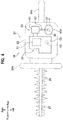
- the brush cutter 1D of the fourth embodiment has the cylinder 51 disposed at a higher position and has the crankcase portion 53 and the fuel suction unit 60 disposed at lower positions, as shown in FIG. 8 .
- the fuel container 90A is attached to the main body 30 so that the connection part 92 is disposed at the lower end of the bag 91, when the brush cutter 1D is operated.
- the bag 91 is disposed so as to be longitudinally perpendicular to the axis of the crankshaft 52. This causes the liquid fuel F in the bag 91 to flow downward along the axis direction of the cylinder 51 (i.e., vertical direction).
- the fuel container 90A is attached to the main body 30 so that the liquid fuel F in the bag 91 flows in the direction orthogonal to the axis of the crankshaft 52 of the internal combustion engine 50 and in the axis direction of the cylinder 51, when the cutter is operated.
- the cylinder 51 of the internal combustion engine 50 is disposed on an upstream side of the flow direction of the liquid fuel F, and the crankcase portion 53 of the internal combustion engine 50 is disposed on a downstream side of the flow direction of the liquid fuel F.
- the cylinder 51 of the internal combustion engine 50 is disposed on the upstream side in the flow direction of the liquid fuel F, and the fuel suction unit 60 is disposed on the downstream side in the flow direction of the liquid fuel F, when the cutter is operated.
- the fuel container 90B of the fifth embodiment includes the bag 91 and a case 93 housing the bag 91, as shown in FIG. 9 .
- the case 93 is a box made of metal or resin for protecting the bag 91, and is formed harder than the bag 91 to have a higher strength.
- the case 93 is detachably attached to the main body of power work equipment.
- the case 93 is provided with a connection hole 93a penetrating through one of its walls.
- the connection part 92 of the bag 91 is inserted through the connection hole 93a, with the front end of the connection part 92 protruded outward from the case 93.
- the case 93 is formed with a vent hole (not shown) for communication between inside and outside thereof.
- the fuel container 90B of the fifth embodiment includes the case 93 housing the bag 91, wherein the case 93 is detachably attached to the main body 10.
- the flexible bag 91 is protected by the case 93 to prevent the bag 91 from being damaged during transportation or storage.
- a bag 101 of a lubricating oil container 100B may be housed in a case 103 made of metal or resin, with the front end of a connection part 102 protruded outward through a connecting hole 103a of the case 103. This makes the flexible bag 101 protected by the case 103.
Landscapes
- Engineering & Computer Science (AREA)
- Mechanical Engineering (AREA)
- General Engineering & Computer Science (AREA)
- Combustion & Propulsion (AREA)
- Chemical & Material Sciences (AREA)
- Life Sciences & Earth Sciences (AREA)
- Wood Science & Technology (AREA)
- Forests & Forestry (AREA)
- Lubrication Details And Ventilation Of Internal Combustion Engines (AREA)
- Lubrication Of Internal Combustion Engines (AREA)
- Control Of Vehicle Engines Or Engines For Specific Uses (AREA)
- Reciprocating Pumps (AREA)
- Portable Power Tools In General (AREA)
Abstract
Description
- The present invention relates to a fuel container and power work equipment.
- Power work equipment, such as a brush cutter, a chainsaw, a hedge trimmer, and a blower, typically includes a main body having an internal combustion engine and a metallic fuel container storing liquid fuel, wherein the fuel container is detachably attached to the main body (see
Patent Document 1, for example). - Patent Document 1: Japanese Patent Application Publication No.
H10-274120 - Once liquid fuel in a sealed fuel container decreases to have a negative pressure in the fuel container, the pump of an internal combustion engine is unable to pump up the liquid fuel any more. Therefore, the above-described conventional power work equipment is provided with a hose to communicate between inside and outside of the fuel container, in order to prevent the fuel container from having a negative pressure therein. This configuration has a problem that the hose must be fixed to a replacing fuel container when the fuel container is replaced, to make the replacement work complicated.
- The present invention is intended to provide a fuel container that is easily replaced for power work equipment to solve the above-identified problems, and supplies liquid fuel having optimum properties for an internal combustion engine of the power work equipment. In addition, the present invention is intended to provide power work equipment that has its fuel container and/or its lubricating oil container easily replaced to solve the above-identified problems, and is supplied with liquid fuel and/or lubricating oil optimized for driving.
- A first aspect of the invention provides a fuel container used for storing liquid fuel to be supplied to an internal combustion engine, including a bag that is flexible and configured to store the liquid fuel. The bag is provided with a connection part to be connected to a fuel suction unit of the internal combustion engine. The bag has the connection part connected with the fuel suction unit in a liquid-tight manner, and is configured to collapse as the liquid fuel in the bag decreases.
- A second aspect of the invention provides power work equipment including a main body having an internal combustion engine, and a fuel container detachably attached to the main body. The fuel container includes a flexible bag to store liquid fuel to be supplied to the internal combustion engine. The bag is provided with a connection part to be connected to a fuel suction unit of the internal combustion engine. The bag has the connection part connected with the fuel suction unit in a liquid-tight manner, and is configured to collapse as the liquid fuel in the bag decreases.
- A third aspect of the invention provides power work equipment including a main body having a drive source, and a lubricating oil container detachably attached to the main body. The lubricating oil container includes a flexible bag to store lubricating oil for lubricating a sliding portion of the power work equipment. The bag is provided with a connection part to be connected to a lubricating-oil suction unit of the drive source. The bag has the connection part connected with the lubricating-oil suction unit in a liquid-tight manner, and is configured to collapse as the lubricating oil in the bag decreases.
- According to the first and second aspects of the invention, the fuel container is attached to the power work equipment to supply the liquid fuel to the internal combustion engine, and is replaced with new one when the liquid fuel in the fuel container runs out, allowing a user to have no messy hands for supplying fuel to the internal combustion engine. According to the third aspect of the invention, the lubricating oil container is attached to the power work equipment to supply the lubricating oil to the sliding portion, and is replaced with new one when the lubricating oil in the lubricating oil container runs out, allowing a user to have no messy hands for resupplying lubricating oil to the sliding portion.
- According to the present invention, the bag internally contracts as the liquid fuel or lubricating oil in the bag decreases, making the bag collapsed to prevent the bag from having negative pressure therein. Therefore, there is no need to set a part for the communication between inside and outside of the bag when a fuel container or a lubricating oil container is attached to power work equipment, allowing for easy replacement of the fuel container or the lubricating oil container.
- According to the first and second aspects of the invention, the fuel container can be produced and sold separately, so that the fuel container is filled with the liquid fuel having the properties compatible with the internal combustion engine so as to be supplied to the user. This allows the internal combustion engine to be driven with the liquid fuel having the optimum properties. According to the third aspect of the invention, the lubricating oil container can be produced and sold separately, so that the lubricating oil container is filled with the lubricating oil suitable for the sliding portion of the power work equipment and the work so as to be supplied to the user. This allows the power work equipment to be driven with the optimum lubricating oil.
- According to the present invention, the bag is deformed while the sealed state is maintained, to let liquid fuel or lubricating oil less likely to be evaporated.
- The fuel container of the present invention is easily replaced for the power work equipment, and supplies the liquid fuel having the optimum properties for the internal combustion engine. The power work equipment of the present invention allows the fuel container or the lubricating oil container to be easily replaced, and is supplied with the liquid fuel or the lubricating oil optimized for driving.
-
-
FIG. 1 is a diagram showing a schematic structure of a chainsaw according to a first embodiment of the present invention, in a side view when the chainsaw is not operated or when the chainsaw is vertically cutting an object to be cut; -
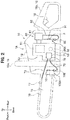
FIG. 2 is a side view of the chainsaw according to the first embodiment of the present invention, to show a state that liquid fuel in a fuel container and lubricating oil in a lubricating oil container have decreased; -
FIG. 3 is a side view of the chainsaw, having another configuration, according to the first embodiment of the present invention; -
FIG. 4 is a diagram showing, in a plan view, a schematic structure of a hedge trimmer according to a second embodiment of the present invention; -
FIG. 5 is a diagram showing, in a side view, a schematic structure of a brush cutter according to a third embodiment of the present invention; -
FIG. 6 is a diagram showing, in a side view, another schematic structure of the brush cutter according to the third embodiment of the present invention; -
FIG. 7 is a diagram showing, in a side view, still another schematic structure of the brush cutter according to the third embodiment of the present invention; -
FIG. 8 is a diagram showing, in a side view, a schematic structure of a brush cutter according to a fourth embodiment of the present invention; -
FIG. 9 is a side view of a fuel container according to a fifth embodiment of the present invention; and -
FIG. 10 is a side view of a lubricating oil container according to the fifth embodiment of the present invention. - Embodiments of the present invention will be described in detail by way of example only and with reference to the drawings as appropriate. Note that the same components in respective embodiments will be denoted by the same reference numerals and duplicate descriptions thereof will be omitted.
- In the following description, an up-down direction, a front-rear direction, and a right-left direction of power work equipment are set for the purpose of illustration of a fuel container and the power work equipment of the embodiments, and is not intended to limit the configurations of the fuel container and the power work equipment of the present invention.
- Additionally, in the following descriptions, the state when the power work equipment is not operated refers to a state when the power work equipment is placed on the ground or a floor during the time of the power work equipment being activated or kept in storage.
- In a first embodiment, a description will be given of a
chainsaw 1A that has a fuel container of the present invention applied thereto, and embodies power work equipment of the present invention. - As shown in
FIG. 1 , thechainsaw 1A of the first embodiment is compact power work equipment for cutting an object to be cut, such as a tree or a board. Thechainsaw 1A includes amain body 10, ahandle 15 that supports themain body 10, aguide bar 16 attached to themain body 10, and afuel container 90A and a lubricatingoil container 100A that are detachably attached to themain body 10. - The
main body 10 includes amain body case 12 made of resin and aninternal combustion engine 50, wherein theinternal combustion engine 50 is housed in themain body case 12. - The
internal combustion engine 50 is a drive source of asaw chain 17 to be described later. Theinternal combustion engine 50 of the first embodiment is a two-stroke engine driven with liquid fuel F having gasoline mixed with lubricating oil. Theinternal combustion engine 50 includes acylinder 51 that has a piston (not shown) housed therein, acrankshaft 52 that is rotated by reciprocating movement of the piston, acrankcase portion 53 that houses thecrankshaft 52, afuel suction unit 60, and a lubricating-oil suction unit 70. - The
internal combustion engine 50 is fixed in themain body case 12 so as to have thecylinder 51 disposed at a higher position and have thecrankcase portion 53 disposed at a lower position, when thechainsaw 1A is not operated. Additionally, theinternal combustion engine 50 has a piston (not shown) in thecylinder 51 moved in the up-down direction, and has thecrankshaft 52 extended in the right-left direction. - The
fuel suction unit 60 is a suction device for suctioning the liquid fuel F from thefuel container 90A, and includes a first positive-displacement pump 61 driven by theinternal combustion engine 50. The first positive-displacement pump 61 of the first embodiment is a diaphragm carburetor to generate a suctioning action. This carburetor includes a storage chamber (not shown) for storing the liquid fuel F, and a rubber film (diaphragm) in the storage chamber is expanded and contracted by a negative pressure generated by the reciprocating motion of a piston (not shown), to suction the liquid fuel F. Thefuel suction unit 60 is juxtaposed to theinternal combustion engine 50 at the rear of the upper portion thereof. Additionally, thefuel suction unit 60 has one end of asuction hose 62 connected thereto. - The
fuel suction unit 60 suctions the liquid fuel F from thefuel container 90A through thesuction hose 62 to generate an air-fuel mixture of the liquid fuel F and air. The air-fuel mixture generated by thefuel suction unit 60 is fed to a combustion chamber in thecylinder 51. - The
guide bar 16 is a plate-like member extending in the front-rear direction, and the rear end of theguide bar 16 is attached to the front end of themain body 10. Theguide bar 16 has anannular saw chain 17 wound around the outer periphery thereof. Thesaw chain 17 has the drive force of thecrankshaft 52 transmitted thereto via a gear (not shown). Thus, thesaw chain 17 is rotated along the outer periphery of theguide bar 16 by a driving force of thecrankshaft 52. This defines the outer periphery of theguide bar 16 as a slidingportion 19 on which thesaw chain 17 is rotated. - The lubricating-
oil suction unit 70 is a suction device for suctioning lubricating oil L from the lubricatingoil container 100A, and includes a second positive-displacement pump 71 driven by theinternal combustion engine 50. The second positive-displacement pump 71 is driven by thecrankshaft 52 being rotated through reciprocating motion of a piston, to suction the lubricating oil L from the lubricatingoil container 100A. - The lubricating-
oil suction unit 70 is disposed in front of, and near, thecrankshaft 52 of theinternal combustion engine 50. Additionally, the lubricating-oil suction unit 70 has one end of asuction hose 72 connected thereto. - The lubricating-
oil suction unit 70 suctions the lubricating oil L from the lubricatingoil container 100A through thesuction hose 72. In addition, the lubricating-oil suction unit 70 feeds the lubricating oil L through asupply hose 73 to the slidingportion 19 of theguide bar 16 on which thesaw chain 17 is rotated. - The
handle 15 includes afront handle 15a and arear handle 15b. Thefront handle 15a is a grip portion disposed on the outer periphery of themain body 10, and is formed by bending a cylindrical member. Therear handle 15b is connected to the rear of themain body 10, and the front of therear handle 15b is disposed at the lower rear of themain body 10. Therear handle 15b is provided with athrottle trigger 18 as an operation means for the user to increase or decrease the rotation speed of thesaw chain 17 in a state of holding thereal handle 15b. - When cutting an object to be cut, such as a tree and a board, with the
chainsaw 1A, the operator holds thefront handle 15a with one hand and holds therear handle 15b with the other hand, to carry thechainsaw 1A. Then, athrottle trigger 18 of therear handle 15b is operated to rotate thesaw chain 17 for thesaw chain 17 to cut the object. Thechainsaw 1A inFIG. 1 is in a state of the operator vertically cutting the object, and is positioned so that the saw chain 17is rotated about a horizontal axis (i.e., rotated vertically). Note that when the operator horizontally cuts the object, thechainsaw 1A is positioned to have thesaw chain 17 rotated laterally. - The
fuel container 90A is a closed container composed of aflexible bag 91. Thebag 91 is provided at one end in the longitudinal direction thereof with aconnection part 92. In the first embodiment, theconnection part 92 is disposed lower than the upper end of thebag 91 when thechainsaw 1A is not operated. Thebag 91 of the first embodiment stores therein the liquid fuel F having gasoline mixed with lubricating oil at a predetermined ratio. Thefuel container 90A is housed in themain body case 12 of themain body 10. Themain body case 12 is formed to have a housing space for thefuel container 90A, under thefuel suction unit 60. Themain body case 12 is formed with an opening for access to the housing space so that thefuel container 90A is put into and taken out of the housing space. In this manner, thefuel container 90A is detachably attached to themain body 10. - When the
chainsaw 1A is not operated and thefuel container 90A is housed in themain body case 12, thefuel container 90A is disposed behind thecrankcase portion 53 and under thefuel suction unit 60. As described above, when thechainsaw 1A is not operated, thefuel container 90A is disposed in a space provided under thefuel suction unit 60 and behind thecrankcase portion 53. - When the liquid fuel F is filled into the
bag 91, thebag 91 is wholly swelled with the increase of the liquid fuel F in thebag 91. In contrast, when the liquid fuel F is discharged from thebag 91, thebag body 91 internally contracts as the liquid fuel F in thebag 91 decreases, and thebag 91 is wholly collapsed, as shown inFIG. 2 . In this manner, thebag 91 is flexible so as to be swelled or collapsed depending on the amount of contents in storage. - A material superior in oil resistance, such as resin or aluminum, may preferably be used as a material of the
bag 91. In addition, the thickness of the material may preferably be set to one between 0.1 mm to 0.5 mm, for example, to secure the strength while securing the flexibility of thebag 91. Further, thebag 91 may preferably be made to have a multiple structure for securing the strength, while the thickness of the material of thebag 91 is made thinner for ensuring flexibility. Moreover, thebag 91 may preferably be made partly or wholly transparent so that the amount of the remaining liquid fuel F in thebag 91 can be seen from outside. - The
bag 91 is formed at one end in the longitudinal direction thereof with a throughhole, to which theconnection part 92 is attached, as shown inFIG. 1 . Theconnection part 92 includes acylindrical body 92a and acap 92b. The base of thecylindrical body 92a is inserted into the throughhole of thebag 91, and thecap 92b is put on the front end of thecylindrical body 92a. When thebag 91 is filled with the liquid fuel F in the production process of thefuel container 90A, the liquid fuel F is injected into thebag 91 through thecylindrical body 92a, and then thebag 91 is closed by a sealing member (not shown). Thereafter, when thefuel container 90A is attached to thechainsaw 1A, thecap 92b is put on thecylindrical body 92a to close the front end of thecylindrical body 92a. At this time, it is preferable not to mix air into thebag 91. - The
connection part 92 is connected to thefuel suction unit 60 through thesuction hose 62 in a liquid-tight manner. The structure to connect theconnection part 92 with thesuction hose 62 is not limited. For example, one end of thesuction hose 62 may be inserted through thecap 92b into thebag 91. Alternatively, one end of thesuction hose 62 may be provided with a cylindrical needle so that the needle is inserted into thecap 92b for inserting one end of thesuction hose 62 into thebag 91. - The lubricating
oil container 100A has substantially the same configuration as thefuel container 90A described above, except that abag 101 stores the lubricating oil L. Therefore, a detailed description about the configuration of the lubricatingoil container 100A will be omitted for the same configuration as thefuel container 90A. - The lubricating
oil container 100A is housed in themain body case 12 of themain body 10, particularly in a housing space in front of the lubricating-oil suction unit 70. The lubricatingoil container 100A is detachably attached to themain body 10. In the first embodiment, aconnection part 102 is positioned lower than the upper end of thebag 101 when thechainsaw 1A is not operated. Theconnection part 102 includes acylindrical body 102a and acap 102b. - The
bag 101 of the lubricatingoil container 100A is flexible so as to be swelled or collapsed according to the amount of the lubricating oil L in storage. Additionally, theconnection part 102 of the lubricatingoil container 100A is connected to the lubricating-oil suction unit 70 through thesuction hose 72 in a liquid-tight manner. - The above-described
chainsaw 1A includes themain body 10 having theinternal combustion engine 50, and thefuel container 90A detachably attached to themain body 10, as shown inFIG. 1 . Thefuel container 90A includes theflexible bag 91 to store the liquid fuel F to be supplied to theinternal combustion engine 50. Thebag 91 is provided with theconnection part 92 to be connected to thefuel suction unit 60 of theinternal combustion engine 50. Thebag 91 has theconnection part 92 connected with thefuel suction unit 60 in a liquid-tight manner, and is configured to collapse as the liquid fuel F in thebag 91 decreases. - In this configuration, the
fuel container 90A is attached to themain body 10 of thechainsaw 1A to supply the liquid fuel F to theinternal combustion engine 50, and is replaced with anotherfuel container 90A when the liquid fuel F in thefuel container 90A runs out, allowing a user to have no messy hands for resupplying fuel to theinternal combustion engine 50. - When the liquid fuel F in the
bag 91 is suctioned by thefuel suction unit 60, thebag 91 internally contracts as the liquid fuel in thebag 91 decreases, as shown inFIG. 2 , making thebag 91 collapsed to prevent thebag 91 from having negative pressure therein. Therefore, there is no need to set any part for the communication between inside and outside of thebag 91 when thefuel container 90A is attached to themain body 10, allowing for easy replacement of thefuel container 90A. - In addition, the
bag 91 is preferably configured to be internally expanded and deformed when the fuel swells during storage, to prevent thebag 91 from having excessive positive pressure therein so that there is no need to set any part for the communication between inside and outside of thebag 91, allowing for easy replacement of thefuel container 90A. - The
fuel container 90A inFIG. 1 can be produced and sold separately, so that thefuel container 90A is filled with the liquid fuel F having the properties compatible with theinternal combustion engine 50 so as to be supplied to the user. This allows theinternal combustion engine 50 to be driven with the liquid fuel F having the optimum properties. - The
internal combustion engine 50 inFIG. 1 is driven with the liquid fuel F mixed with lubricating oil. Then, thebag 91 of thefuel container 90A is filled with the liquid fuel F mixed with the lubricating oil. In this configuration, the liquid fuel F having a mixing ratio compatible with theinternal combustion engine 50 is filled in thebag 91 of thefuel container 90A so as to be supplied to the user, and therefore theinternal combustion engine 50 is driven with the liquid fuel F having the optimum mixing ratio. In other words, the user is unable to change the mixing ratio of the liquid fuel F, and this secures safety and functionality of thechainsaw 1A, and prevents the service life from being shortened. - In addition, the
bag 91 is deformed while maintaining the sealed state thereof, to let the liquid fuel F less likely evaporated. Additionally, as thebag 91 is kept in a sealed state, foreign matter such as dust is prevented from mixing into the liquid fuel F. This allows for extending the service life of a filter installed in the fuel system of theinternal combustion engine 50, and further allows for configuring the fuel system of theinternal combustion engine 50 so as to have no filters. - The
fuel suction unit 60 according to the first embodiment uses the first positive-displacement pump 61, so that the liquid fuel F in thebag 91 is reliably suctioned. - Further, the first positive-
displacement pump 61 is driven by theinternal combustion engine 50, requiring no special drive sources for the first positive-displacement pump 61, and is therefore provided at a relatively low cost. Additionally, as the first positive-displacement pump 61 is driven by theinternal combustion engine 50, if the liquid fuel F in thebag 91 runs out and theinternal combustion engine 50 stops driving, thefuel suction unit 60 also stops operation. Then, the first positive-displacement pump 61 is prevented from executing no-discharge operation, to prevent failures of the first positive-displacement pump 61 and thebag 91. - Still further, the first positive-
displacement pump 61 is operated by the suctioning action generated from theinternal combustion engine 50 being driven, to allow the first positive-displacement pump 61 to be efficiently operated. - Still further, the first positive-
displacement pump 61 is a diaphragm carburetor to have the suctioning action generated from theinternal combustion engine 50 being driven. The structure of an existing carburetor is then convenient for suctioning the liquid fuel F in thebag 91. Additionally, an existing carburetor may preferably be used to reduce manufacturing costs of thefuel suction unit 60. - Furthermore, the
chainsaw 1A of the present embodiment includes the lubricatingoil container 100A detachably attached to themain body 10. The lubricatingoil container 100A includes theflexible bag 101, wherein thebag 101 can store the lubricating oil L to lubricate the slidingportion 19. Thebag 101 is provided with theconnection part 102 to be connected to the lubricating-oil suction unit 70 of theinternal combustion engine 50. Thebag 101 has theconnection part 102 connected with the lubricating-oil suction unit 70 in a liquid-tight manner, and is configured to collapse as the lubricating oil L in thebag 101 decreases. - In this configuration, the lubricating
oil container 100A is attached to thechainsaw 1A to supply the lubricating oil L to the slidingportion 19, and is replaced with another lubricatingoil container 100A when the lubricating oil L in the lubricatingoil container 100A runs out, to allow the user to have no messy hands for resupplying the lubricating oil L to the slidingportion 19. - When the lubricating oil L in the
bag 101 is suctioned by the lubricating-oil suction unit 70, thebag 101 internally contracts as the lubricating oil in thebag 101 decreases, as shown inFIG. 2 , making thebag 101 collapsed to prevent thebag 101 from having negative pressure therein. Therefore, there is no need to set any part for the communication between inside and outside of thebag 101 when the lubricatingoil container 100A is attached to themain body 10, allowing for easy replacement of the lubricatingoil container 100A. - In addition, the
bag 101 is preferably configured to be internally expanded and deformed when the lubricating oil swells during storage, to prevent thebag 101 from having excessive positive pressure therein so that there is no need to set any part for the communication between inside and outside of thebag 101, allowing for easy replacement of the lubricatingoil container 100A. - The lubricating
oil container 100A inFIG. 1 can be produced and sold separately, so that the lubricatingoil container 100A is filled with the lubricating oil L suitable for the slidingportion 19 of thechainsaw 1A and the work so as to be supplied to the user. This allows thechainsaw 1A to be driven with the optimum lubricating oil. - In addition, the
bag 101 is deformed while maintaining the sealed state thereof, to let the lubricating oil L less likely evaporated. Additionally, as thebag 101 is kept in a sealed state, foreign matter such as dust is prevented from mixing into the lubricating oil L. This allows for extending the service life of a filter installed in the lubricating oil system of thechainsaw 1A, and further allows for configuring the lubricating oil system of thechainsaw 1A so as to have no filters. - The lubricating-
oil suction unit 70 according to the first embodiment uses the second-displacement pump 71, so that the lubricating oil L in thebag 101 is reliably suctioned. - Further, the second positive-
displacement pump 71 is driven by theinternal combustion engine 50, requiring no special drive sources for the second positive-displacement pump 71, and is therefore provided at a relatively low cost. - In the
chainsaw 1A of the first embodiment, thebag 91 of thefuel container 90A is provided at one end thereof with theconnection part 92 which is positioned lower than the upper end of thebag 91 when thechainsaw 1A is not operated. Similarly, thebag 101 of the lubricatingoil container 100A is provided at one end thereof with theconnection part 102 which is positioned lower than the upper end of thebag 101 when thechainsaw 1A is not operated. Thefuel container 90A and the lubricatingoil container 100A are attached to themain body 10 so that the liquid fuel F and the lubricating oil L in therespective bags chainsaw 1A is not operated. - The
chainsaw 1A inFIG. 1 is in a state of being started (or not being operated). In this state, the flow direction of the liquid fuel F in thebag 91 is orthogonal to the axial direction of thecrankshaft 52 and in the direction of the piston (not shown) being moved, resulting in the same direction as that of gravitational force. In this case, even if air is mixed in thebag 91, the air is accumulated in the upper part of thebag 91, while the liquid fuel F is supplied to thefuel suction unit 60 from the lower part of thebag 91, away from the air, to allow theinternal combustion engine 50 to be started more favorably. - The
chainsaw 1A inFIG. 1 is also in the state of vertically cutting an object to be cut, such as wood. In this state, the flow direction of the liquid fuel F in thebag 91 or the lubricating oil L in thebag 101 is orthogonal to the axial direction of thecrankshaft 52 and in the direction of the piston (not shown) being moved, resulting in the same direction as that of gravitational force. In this case, even if air is mixed in thebags bags fuel suction unit 60 from the lower part of thebag 91, away from the air in thebag 91, to allow theinternal combustion engine 50 to favorably continue its operation. Similarly, the lubricating oil L is suctioned into the lubricating-oil suction unit 70 from the lower part of thebag 101, away from the air in thebag 101, to allow the slidingportion 19 of thechainsaw 1A to favorably continue its operation. - Additionally, setting the longitudinal orientation of the
bags main body 10 to dispose thefuel container 90A and the lubricatingoil container 100A. - Hereinabove, the first embodiment of the present invention has been described, but the present invention is not limited thereto and the first embodiment may be suitably modified without departing from the scope of the present invention. In the
chainsaw 1A of the first embodiment, thefuel container 90A and the lubricatingoil container 100A are housed in themain body case 12, as shown inFIG. 1 , but there is no limitation in the arrangement and orientation of thefuel container 90A and the lubricatingoil container 100A in themain body 10. For example, thefuel container 90A or the lubricatingoil container 100A may be attached to the outer surface of themain body case 12. Likewise, thebag 101 of the lubricatingoil container 100A of the first embodiment may be disposed in the same area as thebag 91 of thefuel container 90A. - The
fuel suction unit 60 of the first embodiment uses the first positive-displacement pump 61 of a diaphragm carburetor, but the configuration of thefuel suction unit 60 is not limited thereto, and various suction mechanisms can be used. - The
fuel container 90A of the first embodiment is provided at one end in the longitudinal direction of thebag 91 with theconnection part 92, but the shape and size of thebag 91 of thefuel container 90A, the position and shape of theconnection part 92, or the like are not limited thereto and can be suitably set depending on the storage space of thefuel container 90A. - In the
chainsaw 1A of the first embodiment, theconnection part 92 is positioned lower than the upper end of thebag 91 of thefuel container 90A and theconnection part 102 is positioned lower than the upper end of thebag 101 of the lubricatingoil container 100A, when thechainsaw 1A is not operated, but the orientations of thefuel container 90A and the lubricatingoil container 100A are not limited to those in the drawing. For example, as shown inFIG. 3 , theconnection parts bags chainsaw 1A horizontally cuts an object to be cut, such as a tree. - In this configuration, even if air is mixed in the
bag 91, the air is accumulated in the upper part of thebag 91, and thefuel suction portion 60 suctions the liquid fuel F from the lower part of thebag 91, away from the air in thebag 91, to allow theinternal combustion engine 50 to favorably continue its operation. Similarly, even if air is mixed in thebag 101, the lubricatingoil suction part 70 suctions the lubricating oil L from the lower part of thebag 101, away from the air in thebag 101, to allow the slidingportion 19 of thechainsaw 1A to favorably continue its operation. - Note that the
fuel container 90A and the lubricatingoil container 100A may be arranged so that the liquid fuel F and the lubricating oil L respectively flow in directions somewhere between those inFIG. 1 and those inFIG. 3 . That is, the longitudinal orientation of thefuel container 90A and the lubricatingoil container 100A may be inclined to the vertical direction and to the horizontal direction, when thechainsaw 1A is not operated. In this case, theinternal combustion engine 50 or the slidingportion 19 of thechainsaw 1A can keep favorable condition while in cutting operation either in the vertical direction or in the horizontal direction. - The
internal combustion engine 50 of the first embodiment is driven with the liquid fuel F having gasoline mixed with lubricating oil, but the structure of the internal combustion engine is not limited thereto. For example, the internal combustion engine may be driven with liquid fuel having alcohol fuel mixed with lubricating oil. Thebag 91 of thefuel container 90A can store liquid fuel suitable for the configuration of the internal combustion engine. Alternatively, thebag 91 of thefuel container 90A may be used to contain gasoline for a four-stroke internal combustion engine, for example, in which gasoline is separated from lubricating oil. In this configuration, the lubricatingoil container 100A may be disposed in the same area as thebag 91 of thefuel container 90A. - The
internal combustion engine 50 of the first embodiment has thecylinder 51 disposed at a higher position and has thecrankcase portion 53 disposed at a lower position, and has thecrankshaft 52 extended in the right-left direction, when thechainsaw 1A is not operated, but the structure of theengine 50 is not limited thereto. For example, thecylinder 51 and thecrankcase portion 53 may be juxtaposed to each other in the right-left direction. Also, thecrankshaft 52 may be arranged to extend in the front-rear direction or in the up-down direction. - In the first embodiment, a description has been given of the
chainsaw 1A to which the present invention is applied, but the power work equipment to which the present invention is applicable is not limited thereto, and the present invention is applicable to various power work equipment such as a hedge trimmer, a brush cutter, and a blower. - Next, a second embodiment of the present invention will be described. In the second embodiment, a description will be given of a
hedge trimmer 1B that has a fuel container of the present invention applied thereto, and embodies power work equipment of the present invention. - As shown in
FIG. 4 , thehedge trimmer 1B of the second embodiment is a compact power work equipment for cutting an object to be cut, such as plants and hedges. Thehedge trimmer 1B includes amain body 20, afront handle 25a and arear handle 25b that support themain body 20, two (upper and lower)blades main body 20, and thefuel container 90A detachably attached to themain body 20. - When cutting an object to be cut, such as plants and hedges, with the
hedge trimmer 1B, the operator holds thefront handle 25a with one hand and holds therear handle 25b with the other hand, to carry thehedge trimmer 1B. Then, a throttle trigger (not shown) of therear handle 25b is operated to reciprocate one or both of the twoblades - The
internal combustion engine 50 and thefuel container 90A are housed in amain body case 22 of themain body 20 of the second embodiment. Thefuel container 90A is detachably attached to themain body 20. - In the
internal combustion engine 50 of the second embodiment, thecylinder 51 is disposed on the right side and thecrankcase portion 53 is disposed on the left side, when thehedge trimmer 1B is not operated. Additionally, in theinternal combustion engine 50 of the second embodiment, thecrankshaft 52 extends in the vertical direction. - In the
hedge trimmer 1B of the second embodiment, thefuel container 90A is disposed to the left of thefuel suction unit 60, when the trimmer is not operated. Additionally, in the second embodiment, thefuel container 90A is oriented so that theconnection part 92 is disposed at the lower end of thebag 91. - In this manner, the
hedge trimmer 1B of the second embodiment has theconnection part 92 provided at one end of thebag 91 so that theconnection part 92 is positioned lower than the upper end of thebag 91 when thehedge trimmer 1B is not operated. Additionally, thefuel container 90A is attached to themain body 20 so that the liquid fuel F in thebag 91 flows downward, when thehedge trimmer 1B is not operated. - In this configuration, even if air is mixed in the
bag 91, the air is accumulated in the upper part of thebag 91 because thehedge trimmer 1B is started in the state as shown inFIG. 4 , and then the liquid fuel F is suctioned by thefuel suction unit 60 from the lower part of thebag 91, away from the air in thebag 91, to allow theinternal combustion engine 50 to be started more favorably. In addition, as a work using thehedge trimmer 1B is often executed in the state shown inFIG. 4 , even if air is mixed inbag 91 during work, the air is accumulated in the upper part ofbag 91, while the liquid fuel F is suctioned by thefuel suction unit 60 from the lower part of thebag 91, away from the air in thebag 91, to allow theinternal combustion engine 50 to favorably continue its operation. In contrast, as thehedge trimmer 1B is often used with its front side raised and its rear side lowered during work, the flow direction of the liquid fuel F is preferably inclined so as to have more flow from the front side to the rear side, as compared with the setup of thebag 91 inFIG. 4 , to allow theinternal combustion engine 50 to favorably continue its operation, even when thehedge trimmer 1B is used with its front side raised and its rear side lowered. Additionally, setting the longitudinal orientation of thebag 91 vertical or inclined allows for effectively utilizing the space in themain body 10 to dispose thefuel container 90A. - Hereinabove, the second embodiment of the present invention has been described, but the present invention is not limited thereto and the second embodiment may be suitably modified without departing from the scope of the present invention, as with other embodiments.
- Next, a third embodiment of the present invention will be described. In the third embodiment, a description will be given of a
brush cutter 1C that has a fuel container of the present invention applied thereto, and embodies power work equipment of the present invention. - As shown in
FIG. 5 , thebrush cutter 1C of the third embodiment is a compact power work equipment for cutting an object to be cut, such as grass and shrubs. Theinternal combustion engine 50 and thefuel container 90A are housed in amain body case 32 of amain body 30 of thebrush cutter 1C. In addition, the base end of an operatingrod 35 is connected to themain body 30, and a rotary blade (not shown) is attached to the front end of the operatingrod 35. - A
drive transmission shaft 36 is inserted through the operatingrod 35, the front end of thedrive transmission shaft 36 is connected to a rotary shaft of a rotary blade (not shown), and the base end of thedrive transmission shaft 36 is connected to thecrankshaft 52. The rotational driving force of thecrankshaft 52 is transmitted to the rotary blade via thedrive transmission shaft 36 to rotate the rotary blade. - When cutting an object to be cut, such as grass and shrubs, with the
brush cutter 1C, the operator uses a shoulder strap (not shown) of the operatingrod 35 and a U-shaped handle (not shown) to carry thebrush cutter 1C, and operates a throttle lever (not shown) to cut the object with the rotary blade. - The
internal combustion engine 50 of the third embodiment has thecylinder 51 disposed at a higher position and has thecrankcase portion 53 disposed at a lower position. Additionally, theinternal combustion engine 50 of the third embodiment has thecrankshaft 52 extended in the front-rear direction. In thebrush cutter 1C of the third embodiment, thedrive transmission shaft 36 is linearly connected with thecrankshaft 52. When thebrush cutter 1C is operated, thedrive transmission shaft 36 and thecrankshaft 52 are inclined to the horizontal so that the front end is positioned lower than the rear end. - In addition, in the third embodiment, the
fuel container 90A is oriented so that theconnection part 92 is disposed at the front end of thebag 91 and the front end of thebag 91 is positioned lower than the rear end. This makes thebag 91 longitudinally inclined, when thebrush cutter 1C is operated, so as to be oriented in the same direction as the axes of thedrive transmission shaft 36 and thecrankshaft 52. - As described above, in the
brush cutter 1C of the third embodiment, thefuel container 90A is attached to themain body 30 so that the liquid fuel F in thebag 91 flows in the axial direction of thecrankshaft 52 of theinternal combustion engine 50, when the cutter is operated. In this configuration, even if air is mixed in thebag 91, the air is accumulated in the upper part of thebag 91 in many cases when thebrush cutter 1C is operated, while the liquid fuel F is suctioned by thefuel suction unit 60 from the lower part of thebody 91, away from the air in thebag 91. - Hereinabove, the third embodiment of the present invention has been described, but the present invention is not limited thereto and the third embodiment may be suitably modified without departing from the scope of the present invention, as with other embodiments. For example, the front end of the
drive transmission shaft 36 may be connected to the rotary shaft of a blower fan for transmitting the rotational driving force of thecrankshaft 52 to the blower fan, to form a blower that rotates the blower fan to blow away grass or dust. - Further, in the
brush cutter 1C of the third embodiment, thecrankshaft 52 extends in the front-rear direction, but thecrankshaft 52 may extend in the right-left direction to transmit the rotational driving force of thecrankshaft 52 to thedrive transmission shaft 36 via a drive transmission mechanism with a plurality of gears. - Furthermore, when the
fuel container 90A is disposed outside themain body 30, thefuel container 90A is preferably arranged under thefuel suction unit 60 and in a space S1 next to thecrankcase portion 53 of theinternal combustion engine 50, as shown inFIG. 6 . Alternatively, thefuel container 90A may be arranged above thefuel suction unit 60 and in a space S2 next to thecylinder 51 of theinternal combustion engine 50, as shown inFIG. 7 . In these configurations, themain body 30 and thefuel container 90A are compactly set to allow thebrush cutter 1C to be reduced in size. - Note that the
chainsaw 1A inFIG. 1 , thehedge trimmer 1B inFIG. 4 , or the blower (not shown) may also be configured to have thefuel container 90A arranged as in the third embodiment, for themain body fuel container 90A to be compactly arranged to allow the power work equipment to be reduced in size. - Moreover, in the configuration shown in
FIG. 6 , thebag 91 preferably has aninner pipe 94 inserted thereto, where theinner pipe 94 is connected to thefuel suction unit 60 in a liquid-tight manner. This configuration changes the flow direction of the liquid fuel F in thebag 91, as compared with the case where theinner pipe 94 is not provided in thebag 91. Specifically, when theinner pipe 94 is not provided in thebag 91, the liquid fuel F in thebag 91 flows upward (toward the upper part of the bag 91) and air is accumulated on the downstream side in the flow direction (in the upper part of the bag 91). In contrast, when theinner pipe 94 is inserted into thebag 91, the liquid fuel F in thebag 91 flows downward (toward the lower part of the bag 91) and air is accumulated on the upstream side in the flow direction (in the upper part of the bag 91), so that the liquid fuel F is suctioned by thefuel suction unit 60 from a position, away from the air in thebag 91. - Next, a fourth embodiment of the present invention will be described. A
brush cutter 1D of the fourth embodiment has substantially the same configuration as thebrush cutter 1C (seeFIG. 5 ) of the third embodiment described above, except for the orientation of thefuel container 90A. - The
brush cutter 1D of the fourth embodiment has thecylinder 51 disposed at a higher position and has thecrankcase portion 53 and thefuel suction unit 60 disposed at lower positions, as shown inFIG. 8 . Thefuel container 90A is attached to themain body 30 so that theconnection part 92 is disposed at the lower end of thebag 91, when thebrush cutter 1D is operated. Thebag 91 is disposed so as to be longitudinally perpendicular to the axis of thecrankshaft 52. This causes the liquid fuel F in thebag 91 to flow downward along the axis direction of the cylinder 51 (i.e., vertical direction). - As described above, in the
brush cutter 1D of the fourth embodiment, thefuel container 90A is attached to themain body 30 so that the liquid fuel F in thebag 91 flows in the direction orthogonal to the axis of thecrankshaft 52 of theinternal combustion engine 50 and in the axis direction of thecylinder 51, when the cutter is operated. Thecylinder 51 of theinternal combustion engine 50 is disposed on an upstream side of the flow direction of the liquid fuel F, and thecrankcase portion 53 of theinternal combustion engine 50 is disposed on a downstream side of the flow direction of the liquid fuel F. Additionally, in thebrush cutter 1D of the fourth embodiment, thecylinder 51 of theinternal combustion engine 50 is disposed on the upstream side in the flow direction of the liquid fuel F, and thefuel suction unit 60 is disposed on the downstream side in the flow direction of the liquid fuel F, when the cutter is operated. - In this configuration, even if air is mixed in the
bag 91 when thebrush cutter 1D is operated, the air is accumulated in the upper part of thebag 91, while the liquid fuel F is suctioned by thefuel suction unit 60 from the lower part of thebag 91, away from the air in thebag 91. - Hereinabove, the fourth embodiment of the present invention has been described, but the present invention is not limited thereto and the fourth embodiment may be suitably modified without departing from the scope of the present invention, as with other embodiments.
- Next, a
fuel container 90B according to a fifth embodiment of the present invention will be described. Thefuel container 90B of the fifth embodiment includes thebag 91 and acase 93 housing thebag 91, as shown inFIG. 9 . Thecase 93 is a box made of metal or resin for protecting thebag 91, and is formed harder than thebag 91 to have a higher strength. Thecase 93 is detachably attached to the main body of power work equipment. - The
case 93 is provided with aconnection hole 93a penetrating through one of its walls. Theconnection part 92 of thebag 91 is inserted through theconnection hole 93a, with the front end of theconnection part 92 protruded outward from thecase 93. Note that thecase 93 is formed with a vent hole (not shown) for communication between inside and outside thereof. - The
fuel container 90B of the fifth embodiment includes thecase 93 housing thebag 91, wherein thecase 93 is detachably attached to themain body 10. In this configuration, theflexible bag 91 is protected by thecase 93 to prevent thebag 91 from being damaged during transportation or storage. - Hereinabove, the fifth embodiment of the present invention has been described, but the present invention is not limited thereto and the fifth embodiment may be suitably modified without departing from the scope of the present invention, as with other embodiments. Similar to the
fuel container 90B of the fifth embodiment, as shown inFIG. 10 , abag 101 of a lubricatingoil container 100B may be housed in acase 103 made of metal or resin, with the front end of aconnection part 102 protruded outward through a connecting hole 103a of thecase 103. This makes theflexible bag 101 protected by thecase 103. -
- 1A
- Chainsaw (power work equipment of the first embodiment)
- 1B
- Hedge trimmer (power work equipment of the second embodiment)
- 1C
- Brush cutter (power work equipment of the third embodiment)
- 1D
- Brush Cutter (Power work equipment of fourth Embodiment)
- 10
- Main body (first embodiment)
- 12
- Main body case
- 16
- Guide bar
- 17
- Saw chain
- 19
- Sliding portion
- 20
- Main body (second embodiment)
- 22
- Main body case
- 26
- Blade
- 30
- Main body (third embodiment)
- 32
- Main body case
- 35
- Operating rod
- 36
- Drive transmission shaft
- 50
- Internal combustion engine
- 51
- Cylinder
- 52
- Crankshaft
- 53
- Crankcase portion
- 60
- Fuel suction unit
- 61
- First positive-displacement pump
- 62
- Suction hose
- 70
- Lubricating-oil suction unit
- 71
- Second positive-displacement pump
- 72
- Suction hose
- 73
- Supply hose
- 90A
- Fuel container (first to fourth embodiments)
- 90B
- Fuel Container (fifth Embodiment)
- 91
- Bag
- 92
- Connection part
- 93
- Case
- 94
- Inner pipe
- 100A
- Lubricating oil container (first embodiment)
- 100B
- Lubricating oil container (fifth embodiment)
- 101
- Bag
- 102
- Connection part
- 103
- Case
- F
- Liquid fuel
- L
- Lubricating oil.
Claims (15)
- A fuel container used for storing liquid fuel to be supplied to an internal combustion engine, comprising:a bag that is flexible and configured to store the liquid fuel,wherein the bag is provided with a connection part to be connected to a fuel suction unit of the internal combustion engine, andthe bag has the connection part connected with the fuel suction unit in a liquid-tight manner, and is configured to collapse as the liquid fuel in the bag decreases.
- Power work equipment comprising:a main body having an internal combustion engine; anda fuel container detachably attached to the main body,wherein the fuel container includes a bag that is flexible and configured to store liquid fuel to be supplied to the internal combustion engine,
wherein the bag is provided with a connection part to be connected to a fuel suction unit of the internal combustion engine, and
the bag has the connection part connected with the fuel suction unit in a liquid-tight manner, and is configured to collapse as the liquid fuel in the bag decreases. - The power work equipment as claimed in claim 2, wherein
the fuel suction unit includes a positive-displacement pump. - The power work equipment as claimed in claim 3, wherein
the positive-displacement pump is driven by the internal combustion engine. - The power work equipment as claimed in claim 4, wherein
the positive-displacement pump is driven with a suctioning action generated by the internal combustion engine. - The power work equipment as claimed in claim 5, wherein
the positive-displacement pump is a diaphragm carburetor driven by the internal combustion engine to generate a suctioning action. - The power work equipment as claimed in any one of claims 2 to 6, wherein
the internal combustion engine is configured to be driven with the liquid fuel mixed with lubricating oil, and
the bag of the fuel container is filled with the liquid fuel mixed with the lubricating oil. - The power work equipment as claimed in any one of claims 2 to 7, wherein
the fuel container includes a case housing the bag, wherein the case is detachably attached to the main body. - The power work equipment as claimed in any one of claims 2 to 8, wherein
the fuel container is juxtaposed to the fuel suction unit and arranged in a space next to a crankcase portion of the internal combustion engine. - The power work equipment as claimed in any one of claims 2 to 8, wherein
the fuel container is juxtaposed to the fuel suction unit and arranged in a space next to a cylinder of the internal combustion engine. - The power work equipment as claimed in any one of claims 2 to 8, wherein the bag is provided at one end thereof with the connection part, and
the connection part is positioned lower than the upper end of the bag when the power work equipment is not operated. - The power work equipment as claimed in any one of claims 2 to 8, wherein
the bag is provided at one end thereof with the connection part, and
the fuel container is attached to the main body so that the liquid fuel in the bag flows downward when the power work equipment is not operated. - Power work equipment comprising:a main body having a drive source; anda lubricating oil container detachably attached to the main body,wherein the lubricating oil container includes a bag that is flexible and configured to store lubricating oil for lubricating a sliding portion of the power work equipment,
wherein the bag is provided with a connection part to be connected to a lubricating-oil suction unit of the drive source, and
the bag has the connection part connected with the lubricating-oil suction unit in a liquid-tight manner, and is configured to collapse as the lubricating oil in the bag decreases. - The power work equipment as claimed in claim 13, wherein
the lubricating-oil suction unit includes a positive-displacement pump. - The power work equipment as claimed in claim 14, wherein
the positive-displacement pump is driven by the drive source.
Applications Claiming Priority (1)
| Application Number | Priority Date | Filing Date | Title |
|---|---|---|---|
| JP2018151278A JP2020026761A (en) | 2018-08-10 | 2018-08-10 | Fuel container and working machine |
Publications (2)
| Publication Number | Publication Date |
|---|---|
| EP3608073A2 true EP3608073A2 (en) | 2020-02-12 |
| EP3608073A3 EP3608073A3 (en) | 2020-04-08 |
Family
ID=67587686
Family Applications (1)
| Application Number | Title | Priority Date | Filing Date |
|---|---|---|---|
| EP19191124.7A Withdrawn EP3608073A3 (en) | 2018-08-10 | 2019-08-09 | Fuel container and power work equipment |
Country Status (3)
| Country | Link |
|---|---|
| US (1) | US20200049113A1 (en) |
| EP (1) | EP3608073A3 (en) |
| JP (1) | JP2020026761A (en) |
Cited By (1)
| Publication number | Priority date | Publication date | Assignee | Title |
|---|---|---|---|---|
| EP4260996A1 (en) * | 2022-04-11 | 2023-10-18 | Techtronic Cordless GP | Chainsaw comprising a lubrication system for the chainsaw guide bar |
Families Citing this family (3)
| Publication number | Priority date | Publication date | Assignee | Title |
|---|---|---|---|---|
| EP3603898B1 (en) * | 2018-08-03 | 2021-04-14 | Andreas Stihl AG & Co. KG | Manually operated work device |
| CN113118554B (en) * | 2021-04-19 | 2022-08-02 | 格力博(江苏)股份有限公司 | Container for a hand-held cutting tool and hand-held cutting tool comprising such a container |
| DE102022127564A1 (en) | 2022-10-19 | 2024-04-25 | Andreas Stihl Ag & Co. Kg | Hand-held tool |
Citations (1)
| Publication number | Priority date | Publication date | Assignee | Title |
|---|---|---|---|---|
| JPH10274120A (en) | 1997-03-28 | 1998-10-13 | Kioritz Corp | Cassette type fuel cylinder and work machine equipped therewith |
Family Cites Families (16)
| Publication number | Priority date | Publication date | Assignee | Title |
|---|---|---|---|---|
| US2758747A (en) * | 1949-12-10 | 1956-08-14 | Standard Oil Co | Multiple compartment tank |
| US3409714A (en) * | 1966-08-09 | 1968-11-05 | Goodrich Co B F | Fuel tank |
| US3593967A (en) * | 1969-11-28 | 1971-07-20 | Borg Warner | Diaphragm carburetor having fuel channel system for engine idling and acceleration |
| GB9014861D0 (en) * | 1990-07-04 | 1990-08-22 | Sachs Dolmar Uk Limited | A fuel tank for liquid fuel for an internal combustion engine |
| US5344045A (en) * | 1990-12-17 | 1994-09-06 | The Coca-Cola Company | Liquid container system |
| JP3385880B2 (en) * | 1995-11-20 | 2003-03-10 | トヨタ自動車株式会社 | Automotive fuel storage device |
| JP3361459B2 (en) * | 1998-08-21 | 2003-01-07 | トヨタ自動車株式会社 | Fuel tank and vehicle equipped with this |
| US6216649B1 (en) * | 1999-05-19 | 2001-04-17 | Adventech Corporation | Low emission two-cycle internal combustion engine for powering a portable tool |
| US6626157B2 (en) * | 2000-01-26 | 2003-09-30 | Siemens Canada Limited | Apparatus and method to detect fuel leak in a zero-vapor fuel system |
| US7493894B2 (en) * | 2004-02-13 | 2009-02-24 | Kelch Corporation | Tank assembly and components |
| US7578321B2 (en) * | 2005-10-13 | 2009-08-25 | Ford Global Technologies, Llc | Freeze protection for on-board vehicle emissions treatment system |
| US20070166586A1 (en) * | 2005-12-30 | 2007-07-19 | Kevin Marchand | Passive-pumping liquid feed fuel cell system |
| US20080272116A1 (en) * | 2007-05-02 | 2008-11-06 | Martucci Norman S | Fuel bladder apparatus and method |
| FR2955517B1 (en) * | 2010-01-26 | 2012-04-20 | Prospection & Inventions | PRESSURE-TEMPERATURE ABATE AND FUEL CARTRIDGE, FUEL TRANSFER DEVICE, AND HAND FASTENING TOOL WITH PRESSURE SENSOR |
| JP6241456B2 (en) * | 2015-07-08 | 2017-12-06 | トヨタ自動車株式会社 | Fuel tank structure |
| JP6210096B2 (en) * | 2015-07-27 | 2017-10-11 | トヨタ自動車株式会社 | Fuel tank structure |
-
2018
- 2018-08-10 JP JP2018151278A patent/JP2020026761A/en active Pending
-
2019
- 2019-08-09 EP EP19191124.7A patent/EP3608073A3/en not_active Withdrawn
- 2019-08-09 US US16/536,722 patent/US20200049113A1/en not_active Abandoned
Patent Citations (1)
| Publication number | Priority date | Publication date | Assignee | Title |
|---|---|---|---|---|
| JPH10274120A (en) | 1997-03-28 | 1998-10-13 | Kioritz Corp | Cassette type fuel cylinder and work machine equipped therewith |
Cited By (1)
| Publication number | Priority date | Publication date | Assignee | Title |
|---|---|---|---|---|
| EP4260996A1 (en) * | 2022-04-11 | 2023-10-18 | Techtronic Cordless GP | Chainsaw comprising a lubrication system for the chainsaw guide bar |
Also Published As
| Publication number | Publication date |
|---|---|
| EP3608073A3 (en) | 2020-04-08 |
| JP2020026761A (en) | 2020-02-20 |
| US20200049113A1 (en) | 2020-02-13 |
Similar Documents
| Publication | Publication Date | Title |
|---|---|---|
| EP3608073A2 (en) | Fuel container and power work equipment | |
| US5960764A (en) | Four-stroke internal combustion engine | |
| US20110067659A1 (en) | Lubrication system for portable four-stroke engine | |
| EP2363232B1 (en) | Engine-driven cutter | |
| JPH03117662A (en) | Carbureter and oil pump, and making thereof | |
| US8683706B2 (en) | Engine-driven cutter | |
| US8857421B2 (en) | Engine-driven cutter | |
| JP2007224824A (en) | Portable four cycle engine and portable working machine mounted with the engine | |
| US2630844A (en) | Chain saw | |
| US8739418B2 (en) | Engine-driven cutter | |
| US9115645B2 (en) | Engine-driven cutter | |
| US8387595B2 (en) | Lubricating device for four-stroke engine | |
| JP5786553B2 (en) | Two-cycle engine and engine working machine using the same | |
| EP3587753B1 (en) | Small internal combustion engine and gardening tool providing with same | |
| JP5316462B2 (en) | Engine tools | |
| JP5556340B2 (en) | Engine and engine working machine equipped with the same | |
| JPH07255278A (en) | Clipper type bush cleaner | |
| JP7544583B2 (en) | Manual fuel pumps, fuel supply devices, carburetors and handheld work machines | |
| KR102413996B1 (en) | Electric trimmer | |
| US11772485B2 (en) | Engine and work machine | |
| ITBO960027U1 (en) | PERFECTED DEVICE FOR REMOTE CUTTING OF BRANCHES AND SIMILAR. | |
| JP2012159026A (en) | Engine working machine | |
| CN211064245U (en) | Light-weight hedge trimmer easy to assemble and disassemble | |
| CN102562383A (en) | Handheld working machine | |
| JP2018165489A (en) | Engine work machine |
Legal Events
| Date | Code | Title | Description |
|---|---|---|---|
| PUAI | Public reference made under article 153(3) epc to a published international application that has entered the european phase |
Free format text: ORIGINAL CODE: 0009012 |
|
| STAA | Information on the status of an ep patent application or granted ep patent |
Free format text: STATUS: THE APPLICATION HAS BEEN PUBLISHED |
|
| AK | Designated contracting states |
Kind code of ref document: A2 Designated state(s): AL AT BE BG CH CY CZ DE DK EE ES FI FR GB GR HR HU IE IS IT LI LT LU LV MC MK MT NL NO PL PT RO RS SE SI SK SM TR |
|
| AX | Request for extension of the european patent |
Extension state: BA ME |
|
| PUAL | Search report despatched |
Free format text: ORIGINAL CODE: 0009013 |
|
| AK | Designated contracting states |
Kind code of ref document: A3 Designated state(s): AL AT BE BG CH CY CZ DE DK EE ES FI FR GB GR HR HU IE IS IT LI LT LU LV MC MK MT NL NO PL PT RO RS SE SI SK SM TR |
|
| AX | Request for extension of the european patent |
Extension state: BA ME |
|
| RIC1 | Information provided on ipc code assigned before grant |
Ipc: B65D 37/00 20060101ALI20200305BHEP Ipc: F02M 37/06 20060101ALI20200305BHEP Ipc: F16N 7/38 20060101ALI20200305BHEP Ipc: F01M 11/00 20060101ALI20200305BHEP Ipc: B27B 17/12 20060101AFI20200305BHEP Ipc: F02M 37/00 20060101ALI20200305BHEP Ipc: F02B 63/02 20060101ALI20200305BHEP Ipc: F01M 3/00 20060101ALI20200305BHEP Ipc: B67D 7/00 20100101ALI20200305BHEP |
|
| STAA | Information on the status of an ep patent application or granted ep patent |
Free format text: STATUS: REQUEST FOR EXAMINATION WAS MADE |
|
| 17P | Request for examination filed |
Effective date: 20200930 |
|
| RBV | Designated contracting states (corrected) |
Designated state(s): AL AT BE BG CH CY CZ DE DK EE ES FI FR GB GR HR HU IE IS IT LI LT LU LV MC MK MT NL NO PL PT RO RS SE SI SK SM TR |
|
| STAA | Information on the status of an ep patent application or granted ep patent |
Free format text: STATUS: EXAMINATION IS IN PROGRESS |
|
| STAA | Information on the status of an ep patent application or granted ep patent |
Free format text: STATUS: EXAMINATION IS IN PROGRESS |
|
| 17Q | First examination report despatched |
Effective date: 20201116 |
|
| RIC1 | Information provided on ipc code assigned before grant |
Ipc: F02M 37/00 20060101AFI20210409BHEP Ipc: F02M 37/06 20060101ALI20210409BHEP Ipc: F02B 63/02 20060101ALI20210409BHEP Ipc: F01M 3/00 20060101ALI20210409BHEP Ipc: F16N 7/38 20060101ALI20210409BHEP Ipc: B27B 17/00 20060101ALI20210409BHEP Ipc: B27B 17/12 20060101ALI20210409BHEP |
|
| GRAP | Despatch of communication of intention to grant a patent |
Free format text: ORIGINAL CODE: EPIDOSNIGR1 |
|
| STAA | Information on the status of an ep patent application or granted ep patent |
Free format text: STATUS: GRANT OF PATENT IS INTENDED |
|
| INTG | Intention to grant announced |
Effective date: 20210601 |
|
| STAA | Information on the status of an ep patent application or granted ep patent |
Free format text: STATUS: THE APPLICATION IS DEEMED TO BE WITHDRAWN |
|
| 18D | Application deemed to be withdrawn |
Effective date: 20211012 |