EP3607926A1 - Massage device for seat - Google Patents
Massage device for seat Download PDFInfo
- Publication number
- EP3607926A1 EP3607926A1 EP18781004.9A EP18781004A EP3607926A1 EP 3607926 A1 EP3607926 A1 EP 3607926A1 EP 18781004 A EP18781004 A EP 18781004A EP 3607926 A1 EP3607926 A1 EP 3607926A1
- Authority
- EP
- European Patent Office
- Prior art keywords
- pressing portion
- controller
- seat
- adjustment
- massage device
- Prior art date
- Legal status (The legal status is an assumption and is not a legal conclusion. Google has not performed a legal analysis and makes no representation as to the accuracy of the status listed.)
- Granted
Links
Images







Classifications
-
- A—HUMAN NECESSITIES
- A61—MEDICAL OR VETERINARY SCIENCE; HYGIENE
- A61H—PHYSICAL THERAPY APPARATUS, e.g. DEVICES FOR LOCATING OR STIMULATING REFLEX POINTS IN THE BODY; ARTIFICIAL RESPIRATION; MASSAGE; BATHING DEVICES FOR SPECIAL THERAPEUTIC OR HYGIENIC PURPOSES OR SPECIFIC PARTS OF THE BODY
- A61H7/00—Devices for suction-kneading massage; Devices for massaging the skin by rubbing or brushing not otherwise provided for
- A61H7/001—Devices for suction-kneading massage; Devices for massaging the skin by rubbing or brushing not otherwise provided for without substantial movement between the skin and the device
-
- A—HUMAN NECESSITIES
- A61—MEDICAL OR VETERINARY SCIENCE; HYGIENE
- A61H—PHYSICAL THERAPY APPARATUS, e.g. DEVICES FOR LOCATING OR STIMULATING REFLEX POINTS IN THE BODY; ARTIFICIAL RESPIRATION; MASSAGE; BATHING DEVICES FOR SPECIAL THERAPEUTIC OR HYGIENIC PURPOSES OR SPECIFIC PARTS OF THE BODY
- A61H23/00—Percussion or vibration massage, e.g. using supersonic vibration; Suction-vibration massage; Massage with moving diaphragms
- A61H23/04—Percussion or vibration massage, e.g. using supersonic vibration; Suction-vibration massage; Massage with moving diaphragms with hydraulic or pneumatic drive
-
- A—HUMAN NECESSITIES
- A47—FURNITURE; DOMESTIC ARTICLES OR APPLIANCES; COFFEE MILLS; SPICE MILLS; SUCTION CLEANERS IN GENERAL
- A47C—CHAIRS; SOFAS; BEDS
- A47C7/00—Parts, details, or accessories of chairs or stools
- A47C7/62—Accessories for chairs
- A47C7/72—Adaptations for incorporating lamps, radio sets, bars, telephones, ventilation, heating or cooling arrangements or the like
-
- A—HUMAN NECESSITIES
- A61—MEDICAL OR VETERINARY SCIENCE; HYGIENE
- A61H—PHYSICAL THERAPY APPARATUS, e.g. DEVICES FOR LOCATING OR STIMULATING REFLEX POINTS IN THE BODY; ARTIFICIAL RESPIRATION; MASSAGE; BATHING DEVICES FOR SPECIAL THERAPEUTIC OR HYGIENIC PURPOSES OR SPECIFIC PARTS OF THE BODY
- A61H15/00—Massage by means of rollers, balls, e.g. inflatable, chains, or roller chains
-
- A—HUMAN NECESSITIES
- A61—MEDICAL OR VETERINARY SCIENCE; HYGIENE
- A61H—PHYSICAL THERAPY APPARATUS, e.g. DEVICES FOR LOCATING OR STIMULATING REFLEX POINTS IN THE BODY; ARTIFICIAL RESPIRATION; MASSAGE; BATHING DEVICES FOR SPECIAL THERAPEUTIC OR HYGIENIC PURPOSES OR SPECIFIC PARTS OF THE BODY
- A61H23/00—Percussion or vibration massage, e.g. using supersonic vibration; Suction-vibration massage; Massage with moving diaphragms
- A61H23/006—Percussion or tapping massage
-
- A—HUMAN NECESSITIES
- A61—MEDICAL OR VETERINARY SCIENCE; HYGIENE
- A61H—PHYSICAL THERAPY APPARATUS, e.g. DEVICES FOR LOCATING OR STIMULATING REFLEX POINTS IN THE BODY; ARTIFICIAL RESPIRATION; MASSAGE; BATHING DEVICES FOR SPECIAL THERAPEUTIC OR HYGIENIC PURPOSES OR SPECIFIC PARTS OF THE BODY
- A61H7/00—Devices for suction-kneading massage; Devices for massaging the skin by rubbing or brushing not otherwise provided for
-
- A—HUMAN NECESSITIES
- A61—MEDICAL OR VETERINARY SCIENCE; HYGIENE
- A61B—DIAGNOSIS; SURGERY; IDENTIFICATION
- A61B5/00—Measuring for diagnostic purposes; Identification of persons
- A61B5/68—Arrangements of detecting, measuring or recording means, e.g. sensors, in relation to patient
- A61B5/6887—Arrangements of detecting, measuring or recording means, e.g. sensors, in relation to patient mounted on external non-worn devices, e.g. non-medical devices
- A61B5/6893—Cars
-
- A—HUMAN NECESSITIES
- A61—MEDICAL OR VETERINARY SCIENCE; HYGIENE
- A61H—PHYSICAL THERAPY APPARATUS, e.g. DEVICES FOR LOCATING OR STIMULATING REFLEX POINTS IN THE BODY; ARTIFICIAL RESPIRATION; MASSAGE; BATHING DEVICES FOR SPECIAL THERAPEUTIC OR HYGIENIC PURPOSES OR SPECIFIC PARTS OF THE BODY
- A61H2201/00—Characteristics of apparatus not provided for in the preceding codes
- A61H2201/01—Constructive details
- A61H2201/0119—Support for the device
- A61H2201/0138—Support for the device incorporated in furniture
- A61H2201/0149—Seat or chair
-
- A—HUMAN NECESSITIES
- A61—MEDICAL OR VETERINARY SCIENCE; HYGIENE
- A61H—PHYSICAL THERAPY APPARATUS, e.g. DEVICES FOR LOCATING OR STIMULATING REFLEX POINTS IN THE BODY; ARTIFICIAL RESPIRATION; MASSAGE; BATHING DEVICES FOR SPECIAL THERAPEUTIC OR HYGIENIC PURPOSES OR SPECIFIC PARTS OF THE BODY
- A61H2201/00—Characteristics of apparatus not provided for in the preceding codes
- A61H2201/16—Physical interface with patient
- A61H2201/1602—Physical interface with patient kind of interface, e.g. head rest, knee support or lumbar support
- A61H2201/1623—Back
-
- A—HUMAN NECESSITIES
- A61—MEDICAL OR VETERINARY SCIENCE; HYGIENE
- A61H—PHYSICAL THERAPY APPARATUS, e.g. DEVICES FOR LOCATING OR STIMULATING REFLEX POINTS IN THE BODY; ARTIFICIAL RESPIRATION; MASSAGE; BATHING DEVICES FOR SPECIAL THERAPEUTIC OR HYGIENIC PURPOSES OR SPECIFIC PARTS OF THE BODY
- A61H2201/00—Characteristics of apparatus not provided for in the preceding codes
- A61H2201/16—Physical interface with patient
- A61H2201/1602—Physical interface with patient kind of interface, e.g. head rest, knee support or lumbar support
- A61H2201/1645—Physical interface with patient kind of interface, e.g. head rest, knee support or lumbar support contoured to fit the user
- A61H2201/1647—Physical interface with patient kind of interface, e.g. head rest, knee support or lumbar support contoured to fit the user the anatomy of a particular individual
-
- A—HUMAN NECESSITIES
- A61—MEDICAL OR VETERINARY SCIENCE; HYGIENE
- A61H—PHYSICAL THERAPY APPARATUS, e.g. DEVICES FOR LOCATING OR STIMULATING REFLEX POINTS IN THE BODY; ARTIFICIAL RESPIRATION; MASSAGE; BATHING DEVICES FOR SPECIAL THERAPEUTIC OR HYGIENIC PURPOSES OR SPECIFIC PARTS OF THE BODY
- A61H2201/00—Characteristics of apparatus not provided for in the preceding codes
- A61H2201/16—Physical interface with patient
- A61H2201/1602—Physical interface with patient kind of interface, e.g. head rest, knee support or lumbar support
- A61H2201/1654—Layer between the skin and massage elements, e.g. fluid or ball
-
- A—HUMAN NECESSITIES
- A61—MEDICAL OR VETERINARY SCIENCE; HYGIENE
- A61H—PHYSICAL THERAPY APPARATUS, e.g. DEVICES FOR LOCATING OR STIMULATING REFLEX POINTS IN THE BODY; ARTIFICIAL RESPIRATION; MASSAGE; BATHING DEVICES FOR SPECIAL THERAPEUTIC OR HYGIENIC PURPOSES OR SPECIFIC PARTS OF THE BODY
- A61H2201/00—Characteristics of apparatus not provided for in the preceding codes
- A61H2201/16—Physical interface with patient
- A61H2201/1657—Movement of interface, i.e. force application means
- A61H2201/1676—Pivoting
- A61H2201/1678—Means for angularly oscillating massage elements
-
- A—HUMAN NECESSITIES
- A61—MEDICAL OR VETERINARY SCIENCE; HYGIENE
- A61H—PHYSICAL THERAPY APPARATUS, e.g. DEVICES FOR LOCATING OR STIMULATING REFLEX POINTS IN THE BODY; ARTIFICIAL RESPIRATION; MASSAGE; BATHING DEVICES FOR SPECIAL THERAPEUTIC OR HYGIENIC PURPOSES OR SPECIFIC PARTS OF THE BODY
- A61H2201/00—Characteristics of apparatus not provided for in the preceding codes
- A61H2201/50—Control means thereof
- A61H2201/5007—Control means thereof computer controlled
-
- A—HUMAN NECESSITIES
- A61—MEDICAL OR VETERINARY SCIENCE; HYGIENE
- A61H—PHYSICAL THERAPY APPARATUS, e.g. DEVICES FOR LOCATING OR STIMULATING REFLEX POINTS IN THE BODY; ARTIFICIAL RESPIRATION; MASSAGE; BATHING DEVICES FOR SPECIAL THERAPEUTIC OR HYGIENIC PURPOSES OR SPECIFIC PARTS OF THE BODY
- A61H2201/00—Characteristics of apparatus not provided for in the preceding codes
- A61H2201/50—Control means thereof
- A61H2201/5058—Sensors or detectors
- A61H2201/5071—Pressure sensors
-
- A—HUMAN NECESSITIES
- A61—MEDICAL OR VETERINARY SCIENCE; HYGIENE
- A61H—PHYSICAL THERAPY APPARATUS, e.g. DEVICES FOR LOCATING OR STIMULATING REFLEX POINTS IN THE BODY; ARTIFICIAL RESPIRATION; MASSAGE; BATHING DEVICES FOR SPECIAL THERAPEUTIC OR HYGIENIC PURPOSES OR SPECIFIC PARTS OF THE BODY
- A61H2203/00—Additional characteristics concerning the patient
- A61H2203/04—Position of the patient
- A61H2203/0425—Sitting on the buttocks
- A61H2203/0431—Sitting on the buttocks in 90°/90°-position, like on a chair
-
- A—HUMAN NECESSITIES
- A61—MEDICAL OR VETERINARY SCIENCE; HYGIENE
- A61H—PHYSICAL THERAPY APPARATUS, e.g. DEVICES FOR LOCATING OR STIMULATING REFLEX POINTS IN THE BODY; ARTIFICIAL RESPIRATION; MASSAGE; BATHING DEVICES FOR SPECIAL THERAPEUTIC OR HYGIENIC PURPOSES OR SPECIFIC PARTS OF THE BODY
- A61H2205/00—Devices for specific parts of the body
- A61H2205/08—Trunk
- A61H2205/081—Back
Definitions
- the present invention relates to a massage device for a seat.
- Patent Document 1 discloses an example of a massage device that includes a chair body (seat), airbags (pressing portions) incorporated in the chair body, and a control means for controlling intake and discharge of air to and from the airbags.
- Patent Document 1 Japanese Laid-Open Patent Publication No. 2013-215402
- the chair body may be pressed and deformed. This may attenuate the force of the airbags that presses the seat occupant.
- An objective of the present invention is to provide a massage device for a seat that limits the attenuation of a force of a pressing portion that presses a seat occupant.
- a massage device for a seat that solves the above-described problem includes a pressing portion configured to expand to press a seat occupant seated on the seat, an adjustment portion configured to adjust a position of the pressing portion between the seat occupant and the seat, a deformation detector configured to detect deformation of the seat caused by expansion of the pressing portion, and a controller configured to control the adjustment portion based on a detection result of the deformation detector.
- a massage device 1 for a seat (hereinafter simply referred to as "massage device”) is arranged on a seat 2, on which a seat occupant 3 is seated.
- the massage device 1 is separate from the seat 2. Further, it is preferred that the massage device 1 be covered with a cover.
- the seat 2 may be, for example, a sofa or a chair. Alternatively, the seat 2 may be a seat arranged in a vehicle or the like.
- the massage device 1 includes two pressing portions 10, which massage the seat occupant 3, supports 20, which support the pressing portions 10, two adjustment portions 30, which respectively adjust the positions of the pressing portions 10, an angle detector 80 (deformation detector), which adjusts the position of one of the pressing portions 10, a compressor 40 (fluid supply source), which supplies the pressing portions 10 and the adjustment portions 30 with compressed air, a pressure detector 60, which detects the inner pressure of the pressing portion 10 and the adjustment portion 30, and a controller 70, which controls the driving of the compressor 40.
- the massage device 1 includes a first passage 501, which is connected to the two pressing portions 10, a second passage 502, which is connected to the two adjustment portions 30, and a third passage 503, which is connected to the compressor 40.
- the first passage 501 and the second passage 502 are connected to the third passage 503 and extended such that the first passage 501 and the second passage 502 branch from the third passage 503 from each other.
- the pressing portions 10 are arranged in contact with the seat occupant 3.
- the pressing portions 10 are made of elastic materials.
- the pressing portions 10 are bag-shaped members, i.e., airbags.
- the pressing portions 10 expand when air is supplied and contract when air is discharged.
- the pressing portions 10 expand, the pressing portions 10 press the seat occupant 3.
- the supports 20 include a first support 201, which is in contact with the back surface of the seat occupant 3, two second supports 202, which respectively support the pressing portions 10, and two third supports 203, which are in contact with the seat 2 at positions that respectively correspond to the adjustment portions 30.
- Each of the first support 201, the second supports 202, and the third supports 203 is a substantially rectangular plate-shaped member.
- the pressing portions 10 are arranged one by one on the opposite sides of the first support 201 in the longitudinal direction, and the adjustment portions 30 are arranged one by one on the opposite sides of the first support 201 in the longitudinal direction.
- the second supports 202 are coupled one by one to the opposite ends of the first support 201 in the longitudinal direction
- the third supports 203 are coupled one by one to the opposite ends of the first support 201 in the longitudinal direction.
- Each of the second supports 202 and the third supports 203 is pivotally coupled to the corresponding end of the first support 201.
- Each of the second supports 202 and the third supports 203 pivots about a pivotal axis extending in the lateral direction of the first support 201, which is orthogonal to the longitudinal direction.
- the massage device 1 is arranged on the seat 2 such that the second supports 202 are located between the third supports 203 and the seat occupant 3.
- the pressing portions 10 are attached to parts of the second supports 202 facing the seat occupant 3. Further, the adjustment portions 30 are arranged between the second supports 202 and the third supports 203. That is, the adjustment portions 30 are arranged between the pressing portions 10 and the seat 2. The pressing portions 10 are supported by the adjustment portions 30 with the second supports 202 located in between.
- the adjustment portions 30 are supported by the second supports 202 and the third supports 203, which are arranged such that the adjustment portions 30 are located between the second supports 202 and the third supports 203.
- the adjustment portions 30 are bag-shaped members made of elastic materials, that is, airbags.
- the adjustment portions 30 expand in a sectoral manner from the parts of the second and third supports 202 and 203 that are coupled to the first support 201.
- the adjustment portions 30 when the adjustment portions 30 expand, the adjustment portions 30 cause the second supports 202 to pivot toward the seat occupant 3. That is, the adjustment portions 30 adjust the positions of the pressing portions 10 between the seat occupant 3 and the seat 2.
- the angle detector 80 is arranged on the part where the first support 201 and one of the second supports 202 are coupled to each other, that is, one side of the first support 201 in the longitudinal direction.
- the angle detector 80 detects an angle formed by the second support 202 and the first support 201.
- the angle formed by the second support 202 and the first support 201 is an angle formed on a side on which the pressing portion 10 is arranged relative to the second support 202. Since the second support 202 is arranged between the pressing portion 10 and the adjustment portion 30, the angle detector 80 can detect the position of the part of the pressing portion 10 facing the adjustment portion 30. In other words, the angle detector 80 detects the position of a part of the pressing portion 10 supported by the adjustment portion 30 (more specifically, a part supported by the second support 202).
- the part of the pressing portion 10 facing the adjustment portion 30 (the part supported by the adjustment portion 30) is referred to as a "supported part" of the pressing portion 10.
- the angle detector 80 simply needs to be an angular sensor that changes an output voltage in accordance with, for example, a rotational angle.
- the first passage 501, the second passage 502, and the third passage 503 may be formed by, for example, elastic tubes or metal pipes.
- a side of the first passage 501, the second passage 502, and the third passage 503 that is proximate to the compressor 40, which is a supply source of air, is referred to an "upstream side," and a side distant from the compressor 40 is referred to as a "downstream side.”
- the first passage 501 includes a first branch passage 511, which branches from the first passage 501.
- the first branch passage 511 has a first end, which is connected to the first passage 501, and a second end, which is opened to the atmosphere.
- the second passage 502 includes a second branch passage 512, which branches from the second passage 502.
- the second branch passage 512 has a first end, which is connected to the second passage 502, and a second end, which is opened to the atmosphere.
- the first passage 501 includes a first switch valve 521
- the second passage 502 includes a second switch valve 522
- the first branch passage 511 includes a first discharge valve 531
- the second branch passage 512 includes a second discharge valve 532.
- the first switch valve 521, the second switch valve 522, the first discharge valve 531, and the second discharge valve 532 are solenoid valves electrically switched to an open state or a closed state.
- the first switch valve 521 is located upstream of a part where the first passage 501 and the first branch passage 511 are connected to each other in the first passage 501. Further, the second switch valve 522 is located upstream of a part where the second passage 502 and the second branch passage 512 are connected to each other in the second passage 502.
- the first switch valve 521, the second switch valve 522, the first discharge valve 531, and the second discharge valve 532 are selectively switched to the open state, which allows air to flow in the passages where the valves are arranged, and the closed state, which restricts the flow of air in the passages where the valves are arranged.
- first passage 501 includes a first check valve 541
- second passage 502 includes a second check valve 542.
- the first check valve 541 is located upstream of the first switch valve 521.
- the second check valve 542 is located upstream of the second switch valve 522.
- the first check valve 541 allows the flow of air from the compressor 40 toward the pressing portions 10 and restricts the flow of air from the pressing portions 10 toward the compressor 40.
- the second check valve 542 allows the flow of air from the compressor 40 toward the adjustment portions 30 and restricts the flow of air from the adjustment portions 30 toward the compressor 40.
- the pressure detector 60 includes a first pressure detector 601, which detects the inner pressure of the first passage 501, and a second pressure detector 602, which detects the inner pressure of the second passage 502.
- the pressure detector 60 simply needs to be, for example, a pressure sensor that measures the pressure of fluid with a pressure sensitive element and converts the measured pressure into an electrical signal.
- the first pressure detector 601 is located downstream of the first switch valve 521 in the first passage 501.
- the inner pressure of the first passage 501 is the same at any locations between the first switch valve 521 and the pressing portions 10.
- the first pressure detector 601 detects the inner pressure of the pressing portions 10.
- the second pressure detector 602 is located downstream of the second switch valve 522 in the second passage 502.
- the inner pressure of the second passage 502 is the same at any locations between the second switch valve 522 and the adjustment portions 30.
- the second pressure detector 602 detects the inner pressure of the adjustment portions 30.
- the controller 70 is electrically connected to the angle detector 80, the compressor 40, the first switch valve 521, the second switch valve 522, the first discharge valve 531, the second switch valve 522, and the pressure detector 60.
- the controller 70 is configured by a known microcomputer including a CPU, a RAM, a ROM, and the like. By using the CPU to execute the programs read from the ROM, the controller 70 determines information obtained from the angle detector 80 and the pressure detector 60 and controls driving of the compressor 40, the first switch valve 521, the second switch valve 522, the first discharge valve 531, and the second discharge valve 532.
- the compressor 40 When receiving a signal from an operation portion 71, which includes a switch electrically connected to the controller 70, the compressor 40 simply needs to start driving the compressor 40, the first switch valve 521, the second switch valve 522, the first discharge valve 531, and the second discharge valve 532.
- the controller 70 executes a process for massaging the seat occupant 3 illustrated in Fig. 3 .
- the processes of Figs. 4 to 8 are the subroutines of the process of Fig. 3 .
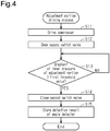
- step S1 the controller 70 executes an adjustment portion driving process. That is, the controller 70 causes the adjustment portions 30 to expand so that the pressing portion 10 contacts the seat occupant 3. In the following description, causing the adjustment portions 30 to expand or contract is also referred to as "driving the adjustment portions 30." The detailed contents of the process will be described in the process of Fig. 4 (described later). Upon completion of the process of step S1, the controller 70 proceeds to step S2.
- step S2 the controller 70 executes an initial time pressing portion driving process. That is, the controller 70 causes the pressing portion 10 to expand so that the pressing portion 10 presses the seat occupant 3. Further, when the seat 2 deforms during expansion of the pressing portion 10, the controller 70 drives the adjustment portion 30. The detailed contents of the process will be described in the process of Fig. 5 (described later). Upon completion of the process of step S2, the controller 70 proceeds to step S3.
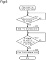
- step S3 the controller 70 executes a pressing portion discharging process. That is, the controller 70 causes air in the pressing portions 10 to be discharged. The detailed contents of this process will be described in the process of Fig. 6 (described later). Upon completion of the process of step S3, the controller 70 proceeds to step S4.
- step S4 the controller 70 determines whether a control end condition is satisfied.
- the "control end condition” may mean that several tens of seconds to several minutes has passed since the operation switch of the operation portion 71 was operated.
- the control end condition may mean that the operation switch has been operated for ending.
- step S4: No the controller 70 proceeds to step S5.
- step S4: Yes the controller 70 proceeds to step S6.
- step S5 the controller 70 executes a pressing portion driving process. That is, the controller 70 causes the pressing portion 10 to expand and press the seat occupant 3. The detailed contents of the process will be described in the process of Fig. 7 (described later). Upon completion of the process of step S5, the controller 70 returns to step S3.
- step S6 the controller 70 executes an adjustment portion discharging process. That is, the controller 70 causes air in the adjustment portion 30 to be discharged. The detailed contents of the process will be described in the process of Fig. 8 (described later). Upon completion of the process of step S6, the controller 70 temporarily ends the current process.
- the controller 70 drives the adjustment portion 30 to cause the pressing portion 10 to contact the seat occupant 3.
- step S11 the controller 70 causes the compressor 40 to be driven. Subsequently, in step S12, the controller 70 opens the second switch valve 522. In this manner, the controller 70 supplies compressed air from the compressor 40 to the adjustment portion 30 to expand the adjustment portion 30. Upon completion of the process of step S12, the controller 70 proceeds to step S13.
- step S13 the controller 70 determines whether the gradient of the inner pressure of the adjustment portion 30 is greater than or equal to a first threshold value.
- the gradient of the inner pressure of the adjustment portion 30 is the amount of change in the inner pressure of the adjustment portion 30 per unit of time, that is, a temporal change rate of the inner pressure of the adjustment portion 30. Further, the inner pressure of the adjustment portion 30 can be obtained from the detection result of the second pressure detector 602.
- the inner pressure of the adjustment portion 30 easily increases. That is, when the gradient of the inner pressure of the adjustment portion 30 until the pressing portion 10 contacts the seat occupant 3 is referred to as a first gradient and the gradient of the inner pressure of the adjustment portion 30 after the pressing portion 10 contacts the seat occupant 3 is referred to as a second gradient, the second gradient is larger than the first gradient.
- the controller 70 can determine whether the pressing portion 10 is in contact with the seat occupant 3.
- step S13: Yes When the gradient of the inner pressure of the adjustment portion 30 is greater than or equal to the first threshold value (step S13: Yes), the controller 70 proceeds to step S14.
- step S13: No When the gradient of the inner pressure of the adjustment portion 30 is less than the first threshold value (step S13: No), the controller 70 returns to step S13.
- the process of step S13 is also referred to as a process of causing the adjustment portion 30 to expand until the pressing portion 10 contacts the seat occupant 3.
- step S14 the controller 70 closes the second switch valve 522. In this manner, the controller 70 restricts the supply of compressed air from the compressor 40 to the adjustment portion 30 so that the adjustment portion 30 stops expanding. Upon completion of the process of step S14, the controller 70 proceeds to step S15.
- step S15 the controller 70 stores the detection result (angle) of the angle detector 80.
- the stored value of the detection result of the angle detector 80 stored by the controller 70 is hereinafter referred to as a "stored value V.”
- the controller 70 Upon completion of the process of step S15, the controller 70 temporarily ends the current process.
- the controller 70 causes the pressing portion 10 to expand to press the seat occupant 3.
- causing the pressing portion 10 to expand or contract is also referred to as “driving the pressing portion 10.”
- the controller 70 drives the adjustment portion 30.
- step S21 the controller 70 opens the first switch valve 521. Since the compressor 40 is driven, compressed air is supplied from the compressor 40 to the pressing portion 10, thereby expanding the pressing portion 10. Upon completion of the process of step S21, the controller 70 proceeds to step S22.
- step S22 the controller 70 determines whether the detection result (pressure) of the first pressure detector 601 is greater than or equal to a second threshold value.
- the second threshold value is a threshold value for setting an upper limit of the pressure of the pressing portion 10 when the seat occupant 3 is massaged.
- the second threshold value be variably set in accordance with the strength of massage desired by the seat occupant 3.
- step S22: Yes When the detection result of the first pressure detector 601 is greater than or equal to the second threshold value (step S22: Yes), the controller 70 proceeds to step S23. When the detection result of the first pressure detector 601 is less than the second threshold value (step S22: No), the controller 70 returns to step S22.
- step S23 the controller 70 closes the first switch valve 521. In this manner, the controller 70 restricts the supply of compressed air from the compressor 40 to the pressing portion 10 so that the pressing portion 10 stops expanding. Upon completion of the process of step S23, the controller 70 proceeds to step S24.
- step S24 the controller 70 determines whether the detection result (angle) of the angle detector 80 is larger than the stored value V. That is, the controller 70 determines whether the seat 2 has been deformed by the expansion of the pressing portion 10.
- the angle formed by the second support 202 and the third support 203 is constant.
- the change amount of the angle formed by the first support 201 and the second support 202 is equal to the change amount of the angle formed by the first support 201 and the third support 203.
- deformation of the seat 2 changes the angle formed by the first support 201 and the third support 203.
- the deformation of the seat 2 caused by the expansion of the pressing portion 10 can be detected by comparing the stored value V with the detection result of the angle detector 80.
- step S24: Yes When the detection result of the angle detector 80 is larger than the stored value V (step S24: Yes), the controller 70 proceeds to step S25. When the detection result of the angle detector 80 is less than or equal to the stored value V (step S24: No), the controller 70 proceeds to step S28.
- the affirmative determination in step S24 indicates that the position of the second support 202 (i.e., the position of the supported part of the pressing portion 10) has moved toward the seat 2 when the first switch valve 521 is open, that is, while the pressing portion 10 is expanding.
- step S25 the controller 70 opens the second switch valve 522. In this manner, the controller 70 supplies compressed air from the compressor 40 to the adjustment portion 30 to expand the adjustment portion 30. Upon completion of the process of step S25, the controller 70 proceeds to step S26.
- step S26 the controller 70 determines whether the detection result of the angle detector 80 is less than or equal to the stored value V. When the detection result of the angle detector 80 is less than or equal to the stored value V (step S26: Yes), the controller 70 proceeds to step S27. When the detection result of the angle detector 80 is larger than the stored value V (step S26: No), the controller 70 proceeds to step S26.
- step S27 the controller 70 closes the second switch valve 522. In this manner, the controller 70 restricts the supply of compressed air from the compressor 40 to the adjustment portions 30 so that the adjustment portion 30 stops expanding.
- the controller 70 changes when the pressing portion 10 is expanded from a contracted state through the processes of steps S24 to S27, the controller 70 causes the adjustment portion 30 to be driven such that the position of the supported part of the pressing portion 10 becomes a position prior to the expansion.
- the controller 70 proceeds to step S28.
- step S28 the controller 70 causes the compressor 40 to stop driving.
- the controller 70 temporarily ends the current process.
- the pressing portion discharging process will now be described with reference to the flowchart in Fig. 6 .
- the controller 70 causes the pressing portion 10 to contract.
- step S31 the controller 70 determines whether a predetermined time has elapsed from the beginning of the process.
- the "predetermined time” may refer to a predetermined fixed value or a variable value that can be changed by the seat occupant 3.
- the predetermined time is a fixed value, the fixed value should be, for example, three seconds to five seconds.
- the controller 70 keeps the pressing portion 10 expanded for the predetermined time so that the seat occupant 3 can feel as if he or she is pressed by the pressing portion 10.
- step S31: Yes the controller 70 proceeds to step S32.
- the controller 70 returns to step S31.
- step S32 the controller 70 opens the first discharge valve 531. In this manner, the controller 70 discharges air in the pressing portion 10 from the first branch passage 511 to contract the pressing portion 10. Upon completion of the process of step S32, the controller 70 proceeds to step S33.
- step S33 the controller 70 determines whether a discharge end condition of the pressing portion 10 is satisfied.
- the "discharge end condition of the pressing portion 10" simply needs to be, for example, that five seconds to ten seconds has elapsed since the first discharge valve 531 was opened in step S32. In this manner, the controller 70 causes the discharge of the pressing portion 10 to continue for a sufficient amount of time.
- the controller 70 proceeds to step S34.
- the controller 70 returns to step S33.
- step S34 the controller 70 closes the first discharge valve 531. In this manner, the controller 70 restricts the supply of air from the pressing portion 10 to the first branch passage 511 so that the pressing portion 10 stops contracting. Upon completion of the process of step S34, the controller 70 temporarily ends the current process.
- the controller 70 causes the pressing portion 10 to expand to press the seat occupant 3.
- step S41 the controller 70 causes the compressor 40 to be driven. Subsequently, in step S42, the controller 70 opens the first switch valve 521. In this manner, the controller 70 supplies compressed air from the compressor 40 to the pressing portion 10 so that the pressing portion 10 expands. Upon completion of the process of step S42, the controller 70 proceeds to step S43.
- step S43 the controller 70 determines whether the detection result (pressure) of the first pressure detector 601 is greater than or equal to the second threshold value.
- the controller 70 causes the pressing portion 10 to expand until the force of pressing the seat occupant 3 with the pressing portion 10 becomes proper.
- the pressing portion 10 is expanded, the position of the supported part of the pressing portion 10 may be changed. In this case, the adjustment portion 30 is not driven.
- step S43: Yes the controller 70 proceeds to step S44.
- step S43: No the controller 70 returns to step S43.
- step S44 the controller 70 closes the first switch valve 521. In this manner, the controller 70 restricts the supply of compressed air from the compressor 40 to the pressing portion 10 so that the pressing portion 10 stops expanding.
- step S45 the controller 70 causes the compressor 40 to stop driving, thereby temporarily ending the current process.
- step S51 the controller 70 opens the second discharge valve 532. In this manner, the controller 70 discharges air in the adjustment portion 30 from the second branch passage 512 so that the adjustment portion 30 contracts. Upon completion of the process of step S51, the controller 70 proceeds to step S52.
- step S52 the controller 70 determines whether a discharge end condition of the adjustment portion 30 is satisfied.
- the "discharge end condition of the adjustment portion 30" simply needs to be, for example, that several seconds has elapsed since the second discharge valve 532 was opened in step S51. In this manner, the controller 70 causes the discharge of the adjustment portion 30 to continue for a sufficient amount of time.
- step S52: Yes the controller 70 proceeds to step S53.
- step S52: No the controller 70 returns to step S52.
- step S53 the controller 70 closes the second discharge valve 532. In this manner, the controller 70 restricts the discharge of air from the adjustment portion 30 to the second branch passage 512 so that the adjustment portion 30 stops contracting. Upon completion of the process of step S53, the controller 70 temporarily ends the current process.
- Fig. 9 shows an initial state in which the pressing portions 10 and the adjustment portions 30 are contracted.
- the massage device 1 is arranged on the seat 2. In this state, the first support 201 and the third supports 203 are in contact with the backrest of the seat 2. Then, the massage device 1 receives a signal from the operation portion 71 to start massaging the seat occupant 3.
- the adjustment portions 30 first expand so that the second supports 202 pivot toward the seat occupant 3.
- the adjustment portions 30 stop expanding and the second supports 202 stop pivoting.
- the pressing portions 10 expand to press the seat occupant 3.
- the third supports 203 press the seat 2 with reactions acting on actions of the pressing portions 10 that press the seat occupant 3.
- the second supports 202, the third supports 203, and the adjustment portions 30 pivot toward the seat 2, thereby recessing and deforming the seat 2.
- the adjustment portions 30 start expanding and the second supports 202 pivot toward the seat occupant 3.
- the adjustment portions 30 stop expanding.
- the pressing portions 10 stop expanding.
- the pressing portions 10 contract.
- the massage device 1 repeatedly expands and contracts the pressing portions 10 until the elapse of a certain time since receiving a signal from the operation portion 71. In this manner, the massage device 1 massages the seat occupant 3.
- the massage device 1 may be, for example, incorporated in the seat 2.
- the adjustment portion 30 can be driven such that the pressing portion 10 properly contacts the seat occupant 3.
- a sensor that detects deformation of the seat 2 incorporated in the seat 2 (one example of a deformation detector) may be arranged. This sensor simply needs to be, for example, a movement sensor that detects movement in the front-rear direction of the surface of the seat 2.
- a flow rate gauge may be used instead of the first pressure detector 601, a flow rate gauge may be used.
- the flow rate gauge may be arranged at a position of the first passage 501 where the first pressure detector 601 is arranged to detect the amount of air supplied to the pressing portion 10 and the amount of air discharged from the pressing portion 10.
- a process of causing the adjustment portion 30 to contract may be performed. This reduces the pressing of the seat occupant 3 by the second support 202 regardless of whether the pressing portion 10 expands or contracts.
- the adjustment portion 30 may be driven in accordance with a change in the detection result of the angle detector 80.
- the adjustment portion 30 may be driven. That is, after driving of the pressing portion 10 is initially started to perform a massaging process, the detection by the angle detector 80 and the driving of the adjustment portion 30 based on the detection result may be performed at any time.
- the adjustment portion 30 does not have to perform the adjustment portion discharging process in step S6 of Fig. 3 . This eliminates the need to expand the adjustment portion 30 when the seat occupant 3 performs massaging again. In this case, for example, when an end switch arranged on the operation portion 71 is operated, it is preferred that air in the adjustment portion 30 be discharged.
- step S13 in Fig. 4 is performed based on the gradient of the inner pressure of the adjustment portion 30.
- the determination may be performed based on the value of the inner pressure of the adjustment portion 30.
- the first threshold value be set in advance in accordance with, for example, the volume of the adjustment portion 30 and the amount of air discharged by the compressor 40.
- step S13 in Fig. 4 may be performed based on a change amount per unit of time of the angle formed by the second support 202 and the first support 201.
- a threshold value simply needs to be set between a change amount per unit of time of the angle formed by the second support 202 and the first support 201 until the pressing portion 10 contacts the seat occupant 3 and a change amount per unit of time of the angle formed by the second support 202 and the first support 201 after the pressing portion 10 contacts the seat occupant 3.
- the second pressure detector 602 is not provided, the contact of the pressing portion 10 with the seat occupant 3 can be detected.
- the second threshold value may be a fixed value or may be continuously or gradually variable. When the second threshold value is variable, it is preferred that the second threshold value be switched by a switch arranged on the operation portion 71. This allows the seat occupant 3 to change how strongly the pressing portion 10 presses the seat occupant 3.
- step S5 in Fig. 3 may be set as the same as the process performed in step S2 in Fig. 3 . This limits the attenuation of a force of the pressing portion 10 that presses the seat occupant 3 even if the pressing portion 10 repeatedly expands and contracts to increase the deformation amount of the seat 2.
- the massage device 1 may be arranged on the seating surface of the seat 2.
- the pressing portions 10 massage, for example, the sides of the thighs of the seat occupant 3.
- the adjustment portions 30 do not have to be elastic bag-shaped members.
- the adjustment portions 30 may be actuators that pivot the second supports 202.
- the supports 20 do not have to be arranged.
- the pressing portions 10 and the adjustment portions 30 may be coupled to each other in series in the front-rear direction of the seat 2.
- the second supports 202 and the third supports 203 do not have to be coupled to each other pivotally relative to the first support 201 and simply need to be movable relative to the first support 201.
- the angle detector 80 simply needs to be replaced with a sensor that detects movement of the second supports 202 relative to the first support 201, that is, movement of the position of the supported parts of the pressing portions 10 relative to the first support 201.
- the angle detector 80 may be arranged on each of the opposite sides of the first support 201, that is, the coupled part of the first support 201 and each second support 202. This allows deformation of the seat 2 to be detected more accurately.
- the first switch valve 521 may be arranged at two portions of the first passage 501 that branch and extend toward the two pressing portions 10. This allows the two pressing portions 10 to expand and contract independently from each other.
- the second switch valve 522 may be arranged at two portions of the second passage 502 that branch and extend toward the two adjustment portions 30. This allows the two adjustment portions 30 to expand and contract independently from each other.
- the controller 70 is not limited to one that performs software processing on all processes executed by itself.
- the controller 70 may include a dedicated hardware circuit (for example, application specific integrated circuit: ASIC) that executes hardware processing on at least part of the processes executed by itself.
- the controller 70 may be circuitry including: 1) one or more processors that operate according to a computer program (software); 2) one or more dedicated hardware circuits that execute at least part of various processes, or 3) a combination thereof.
- the processor includes a CPU and memories such as a RAM and a ROM.
- the memories store program codes or commands configured to cause the CPU to execute processes.
- the memories, or computer readable media include any type of media that are accessible by general-purpose computers and dedicated computers.
Landscapes
- Health & Medical Sciences (AREA)
- Epidemiology (AREA)
- Pain & Pain Management (AREA)
- Physical Education & Sports Medicine (AREA)
- Rehabilitation Therapy (AREA)
- Life Sciences & Earth Sciences (AREA)
- Animal Behavior & Ethology (AREA)
- General Health & Medical Sciences (AREA)
- Public Health (AREA)
- Veterinary Medicine (AREA)
- Dermatology (AREA)
- Massaging Devices (AREA)
Abstract
Description
- The present invention relates to a massage device for a seat.
- Conventionally, massage devices that massage a seat occupant seated in a seat have been known.
Patent Document 1 discloses an example of a massage device that includes a chair body (seat), airbags (pressing portions) incorporated in the chair body, and a control means for controlling intake and discharge of air to and from the airbags. - Patent Document 1: Japanese Laid-Open Patent Publication No.
2013-215402 - In the above-described massage device, during expansion of the airbags, the chair body may be pressed and deformed. This may attenuate the force of the airbags that presses the seat occupant.
- An objective of the present invention is to provide a massage device for a seat that limits the attenuation of a force of a pressing portion that presses a seat occupant.
- A massage device for a seat that solves the above-described problem includes a pressing portion configured to expand to press a seat occupant seated on the seat, an adjustment portion configured to adjust a position of the pressing portion between the seat occupant and the seat, a deformation detector configured to detect deformation of the seat caused by expansion of the pressing portion, and a controller configured to control the adjustment portion based on a detection result of the deformation detector.
-
-
Fig. 1 is a perspective view showing a usage of a massage device for a seat according to an embodiment. -
Fig. 2 is a diagram showing the massage device ofFig. 1 . -
Fig. 3 is a flowchart of a process executed when the controller of the massage device shown inFig. 2 massages a seat occupant. -
Fig. 4 is a flowchart of an adjustment portion driving process executed by the controller of the massage device shown inFig. 2 . -
Fig. 5 is a flowchart of an initial time pressing portion driving process executed by the controller of the massage device shown inFig. 2 . -
Fig. 6 is a flowchart of a pressing portion discharging process executed by the controller of the massage device shown inFig. 2 . -
Fig. 7 is a flowchart of a pressing portion driving process executed by the controller of the massage device shown inFig. 2 . -
Fig. 8 is a flowchart of an adjustment portion discharging process executed by the controller of the massage device shown inFig. 2 . -
Fig. 9 is a plan view showing the pressing portions and the adjustment portions prior to being driven in the massage device ofFig. 2 . -
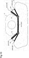
Fig. 10 is a plan view showing expansion of the adjustment portions in the massage device ofFig. 9 . -
Fig. 11 is a plan view showing expansion of the pressing portions in the massage device ofFig. 10 . -
Fig. 12 is a plan view showing deformation of the seat by the massage device ofFig. 11 . -
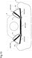
Fig. 13 is a plan view showing expansion of the adjustment portions in accordance with the deformation of the seat ofFig. 12 . - A massage device for a seat according to an embodiment will now be described with reference to the drawings.
- As shown in
Fig. 1 , amassage device 1 for a seat (hereinafter simply referred to as "massage device") is arranged on aseat 2, on which aseat occupant 3 is seated. Themassage device 1 is separate from theseat 2. Further, it is preferred that themassage device 1 be covered with a cover. Theseat 2 may be, for example, a sofa or a chair. Alternatively, theseat 2 may be a seat arranged in a vehicle or the like. - As shown in
Fig. 2 , themassage device 1 includes twopressing portions 10, which massage theseat occupant 3, supports 20, which support thepressing portions 10, twoadjustment portions 30, which respectively adjust the positions of thepressing portions 10, an angle detector 80 (deformation detector), which adjusts the position of one of thepressing portions 10, a compressor 40 (fluid supply source), which supplies thepressing portions 10 and theadjustment portions 30 with compressed air, apressure detector 60, which detects the inner pressure of thepressing portion 10 and theadjustment portion 30, and acontroller 70, which controls the driving of thecompressor 40. - Further, the
massage device 1 includes afirst passage 501, which is connected to the twopressing portions 10, asecond passage 502, which is connected to the twoadjustment portions 30, and athird passage 503, which is connected to thecompressor 40. Thefirst passage 501 and thesecond passage 502 are connected to thethird passage 503 and extended such that thefirst passage 501 and thesecond passage 502 branch from thethird passage 503 from each other. - As shown in
Fig. 2 , thepressing portions 10 are arranged in contact with theseat occupant 3. The pressingportions 10 are made of elastic materials. Further, thepressing portions 10 are bag-shaped members, i.e., airbags. Thus, thepressing portions 10 expand when air is supplied and contract when air is discharged. When thepressing portions 10 expand, thepressing portions 10 press theseat occupant 3. - The
supports 20 include afirst support 201, which is in contact with the back surface of theseat occupant 3, twosecond supports 202, which respectively support thepressing portions 10, and twothird supports 203, which are in contact with theseat 2 at positions that respectively correspond to theadjustment portions 30. Each of thefirst support 201, the second supports 202, and thethird supports 203 is a substantially rectangular plate-shaped member. Thepressing portions 10 are arranged one by one on the opposite sides of thefirst support 201 in the longitudinal direction, and theadjustment portions 30 are arranged one by one on the opposite sides of thefirst support 201 in the longitudinal direction. - The
second supports 202 are coupled one by one to the opposite ends of thefirst support 201 in the longitudinal direction, and thethird supports 203 are coupled one by one to the opposite ends of thefirst support 201 in the longitudinal direction. Each of thesecond supports 202 and thethird supports 203 is pivotally coupled to the corresponding end of thefirst support 201. Each of the second supports 202 and the third supports 203 pivots about a pivotal axis extending in the lateral direction of thefirst support 201, which is orthogonal to the longitudinal direction. Further, themassage device 1 is arranged on theseat 2 such that thesecond supports 202 are located between thethird supports 203 and theseat occupant 3. - The
pressing portions 10 are attached to parts of thesecond supports 202 facing theseat occupant 3. Further, theadjustment portions 30 are arranged between thesecond supports 202 and the third supports 203. That is, theadjustment portions 30 are arranged between thepressing portions 10 and theseat 2. The pressingportions 10 are supported by theadjustment portions 30 with thesecond supports 202 located in between. - The
adjustment portions 30 are supported by thesecond supports 202 and thethird supports 203, which are arranged such that theadjustment portions 30 are located between thesecond supports 202 and the third supports 203. In the same manner as thepressing portions 10, theadjustment portions 30 are bag-shaped members made of elastic materials, that is, airbags. Theadjustment portions 30 expand in a sectoral manner from the parts of the second and third supports 202 and 203 that are coupled to thefirst support 201. Thus, when theadjustment portions 30 expand, theadjustment portions 30 cause the second supports 202 to pivot toward theseat occupant 3. That is, theadjustment portions 30 adjust the positions of thepressing portions 10 between theseat occupant 3 and theseat 2. - The
angle detector 80 is arranged on the part where thefirst support 201 and one of thesecond supports 202 are coupled to each other, that is, one side of thefirst support 201 in the longitudinal direction. Theangle detector 80 detects an angle formed by thesecond support 202 and thefirst support 201. The angle formed by thesecond support 202 and thefirst support 201 is an angle formed on a side on which thepressing portion 10 is arranged relative to thesecond support 202. Since thesecond support 202 is arranged between thepressing portion 10 and theadjustment portion 30, theangle detector 80 can detect the position of the part of thepressing portion 10 facing theadjustment portion 30. In other words, theangle detector 80 detects the position of a part of thepressing portion 10 supported by the adjustment portion 30 (more specifically, a part supported by the second support 202). The part of thepressing portion 10 facing the adjustment portion 30 (the part supported by the adjustment portion 30) is referred to as a "supported part" of thepressing portion 10. Theangle detector 80 simply needs to be an angular sensor that changes an output voltage in accordance with, for example, a rotational angle. - The
first passage 501, thesecond passage 502, and thethird passage 503 may be formed by, for example, elastic tubes or metal pipes. In the following description, a side of thefirst passage 501, thesecond passage 502, and thethird passage 503 that is proximate to thecompressor 40, which is a supply source of air, is referred to an "upstream side," and a side distant from thecompressor 40 is referred to as a "downstream side." - The
first passage 501 includes afirst branch passage 511, which branches from thefirst passage 501. Thefirst branch passage 511 has a first end, which is connected to thefirst passage 501, and a second end, which is opened to the atmosphere. Further, thesecond passage 502 includes asecond branch passage 512, which branches from thesecond passage 502. Thesecond branch passage 512 has a first end, which is connected to thesecond passage 502, and a second end, which is opened to the atmosphere. - The
first passage 501 includes afirst switch valve 521, and thesecond passage 502 includes asecond switch valve 522. Thefirst branch passage 511 includes afirst discharge valve 531, and thesecond branch passage 512 includes asecond discharge valve 532. Thefirst switch valve 521, thesecond switch valve 522, thefirst discharge valve 531, and thesecond discharge valve 532 are solenoid valves electrically switched to an open state or a closed state. - The
first switch valve 521 is located upstream of a part where thefirst passage 501 and thefirst branch passage 511 are connected to each other in thefirst passage 501. Further, thesecond switch valve 522 is located upstream of a part where thesecond passage 502 and thesecond branch passage 512 are connected to each other in thesecond passage 502. - The
first switch valve 521, thesecond switch valve 522, thefirst discharge valve 531, and thesecond discharge valve 532 are selectively switched to the open state, which allows air to flow in the passages where the valves are arranged, and the closed state, which restricts the flow of air in the passages where the valves are arranged. - In addition, the
first passage 501 includes afirst check valve 541, and thesecond passage 502 includes asecond check valve 542. Thefirst check valve 541 is located upstream of thefirst switch valve 521. Thesecond check valve 542 is located upstream of thesecond switch valve 522. Thefirst check valve 541 allows the flow of air from thecompressor 40 toward thepressing portions 10 and restricts the flow of air from thepressing portions 10 toward thecompressor 40. Further, thesecond check valve 542 allows the flow of air from thecompressor 40 toward theadjustment portions 30 and restricts the flow of air from theadjustment portions 30 toward thecompressor 40. - The
pressure detector 60 includes afirst pressure detector 601, which detects the inner pressure of thefirst passage 501, and asecond pressure detector 602, which detects the inner pressure of thesecond passage 502. Thepressure detector 60 simply needs to be, for example, a pressure sensor that measures the pressure of fluid with a pressure sensitive element and converts the measured pressure into an electrical signal. Thefirst pressure detector 601 is located downstream of thefirst switch valve 521 in thefirst passage 501. The inner pressure of thefirst passage 501 is the same at any locations between thefirst switch valve 521 and thepressing portions 10. Thus, thefirst pressure detector 601 detects the inner pressure of thepressing portions 10. In addition, thesecond pressure detector 602 is located downstream of thesecond switch valve 522 in thesecond passage 502. The inner pressure of thesecond passage 502 is the same at any locations between thesecond switch valve 522 and theadjustment portions 30. Thus, thesecond pressure detector 602 detects the inner pressure of theadjustment portions 30. - The
controller 70 is electrically connected to theangle detector 80, thecompressor 40, thefirst switch valve 521, thesecond switch valve 522, thefirst discharge valve 531, thesecond switch valve 522, and thepressure detector 60. Thecontroller 70 is configured by a known microcomputer including a CPU, a RAM, a ROM, and the like. By using the CPU to execute the programs read from the ROM, thecontroller 70 determines information obtained from theangle detector 80 and thepressure detector 60 and controls driving of thecompressor 40, thefirst switch valve 521, thesecond switch valve 522, thefirst discharge valve 531, and thesecond discharge valve 532. When receiving a signal from anoperation portion 71, which includes a switch electrically connected to thecontroller 70, thecompressor 40 simply needs to start driving thecompressor 40, thefirst switch valve 521, thesecond switch valve 522, thefirst discharge valve 531, and thesecond discharge valve 532. - The contents of control performed by the
massage device 1 will now be described. - The
controller 70 executes a process for massaging theseat occupant 3 illustrated inFig. 3 . The processes ofFigs. 4 to 8 are the subroutines of the process ofFig. 3 . - First, the process of massaging the
seat occupant 3 will now be described with reference to the flowchart ofFig. 3 . This process is started when theseat occupant 3 operates an operation switch arranged on theoperation portion 71. Before the process ofFig. 3 starts, thepressing portion 10 and theadjustment portion 30 are contracted, thecompressor 40 is stopped, and thefirst switch valve 521, thesecond switch valve 522, thefirst discharge valve 531, and thesecond discharge valve 532 are closed. - In step S1, the
controller 70 executes an adjustment portion driving process. That is, thecontroller 70 causes theadjustment portions 30 to expand so that thepressing portion 10 contacts theseat occupant 3. In the following description, causing theadjustment portions 30 to expand or contract is also referred to as "driving theadjustment portions 30." The detailed contents of the process will be described in the process ofFig. 4 (described later). Upon completion of the process of step S1, thecontroller 70 proceeds to step S2. - In step S2, the
controller 70 executes an initial time pressing portion driving process. That is, thecontroller 70 causes thepressing portion 10 to expand so that thepressing portion 10 presses theseat occupant 3. Further, when theseat 2 deforms during expansion of thepressing portion 10, thecontroller 70 drives theadjustment portion 30. The detailed contents of the process will be described in the process ofFig. 5 (described later). Upon completion of the process of step S2, thecontroller 70 proceeds to step S3. - In step S3, the
controller 70 executes a pressing portion discharging process. That is, thecontroller 70 causes air in thepressing portions 10 to be discharged. The detailed contents of this process will be described in the process ofFig. 6 (described later). Upon completion of the process of step S3, thecontroller 70 proceeds to step S4. - In step S4, the
controller 70 determines whether a control end condition is satisfied. For example, the "control end condition" may mean that several tens of seconds to several minutes has passed since the operation switch of theoperation portion 71 was operated. Alternatively, the control end condition may mean that the operation switch has been operated for ending. When the control end condition is not satisfied (step S4: No), thecontroller 70 proceeds to step S5. When the control end condition is satisfied (step S4: Yes), thecontroller 70 proceeds to step S6. - In step S5, the
controller 70 executes a pressing portion driving process. That is, thecontroller 70 causes thepressing portion 10 to expand and press theseat occupant 3. The detailed contents of the process will be described in the process ofFig. 7 (described later). Upon completion of the process of step S5, thecontroller 70 returns to step S3. - In step S6, the
controller 70 executes an adjustment portion discharging process. That is, thecontroller 70 causes air in theadjustment portion 30 to be discharged. The detailed contents of the process will be described in the process ofFig. 8 (described later). Upon completion of the process of step S6, thecontroller 70 temporarily ends the current process. - The adjustment portion driving process will now be described with reference to the flowchart of
Fig. 4 . In this process, thecontroller 70 drives theadjustment portion 30 to cause thepressing portion 10 to contact theseat occupant 3. - In step S11, the
controller 70 causes thecompressor 40 to be driven. Subsequently, in step S12, thecontroller 70 opens thesecond switch valve 522. In this manner, thecontroller 70 supplies compressed air from thecompressor 40 to theadjustment portion 30 to expand theadjustment portion 30. Upon completion of the process of step S12, thecontroller 70 proceeds to step S13. - In step S13, the
controller 70 determines whether the gradient of the inner pressure of theadjustment portion 30 is greater than or equal to a first threshold value. The gradient of the inner pressure of theadjustment portion 30 is the amount of change in the inner pressure of theadjustment portion 30 per unit of time, that is, a temporal change rate of the inner pressure of theadjustment portion 30. Further, the inner pressure of theadjustment portion 30 can be obtained from the detection result of thesecond pressure detector 602. - When the
pressing portion 10 contacts theseat occupant 3 during expansion of theadjustment portion 30, the inner pressure of theadjustment portion 30 easily increases. That is, when the gradient of the inner pressure of theadjustment portion 30 until thepressing portion 10 contacts theseat occupant 3 is referred to as a first gradient and the gradient of the inner pressure of theadjustment portion 30 after thepressing portion 10 contacts theseat occupant 3 is referred to as a second gradient, the second gradient is larger than the first gradient. Thus, when the first threshold value is set to be larger than the first gradient and smaller than the second gradient, thecontroller 70 can determine whether thepressing portion 10 is in contact with theseat occupant 3. - When the gradient of the inner pressure of the
adjustment portion 30 is greater than or equal to the first threshold value (step S13: Yes), thecontroller 70 proceeds to step S14. When the gradient of the inner pressure of theadjustment portion 30 is less than the first threshold value (step S13: No), thecontroller 70 returns to step S13. Thus, the process of step S13 is also referred to as a process of causing theadjustment portion 30 to expand until thepressing portion 10 contacts theseat occupant 3. - In step S14, the
controller 70 closes thesecond switch valve 522. In this manner, thecontroller 70 restricts the supply of compressed air from thecompressor 40 to theadjustment portion 30 so that theadjustment portion 30 stops expanding. Upon completion of the process of step S14, thecontroller 70 proceeds to step S15. - In step S15, the
controller 70 stores the detection result (angle) of theangle detector 80. The stored value of the detection result of theangle detector 80 stored by thecontroller 70 is hereinafter referred to as a "stored value V." Upon completion of the process of step S15, thecontroller 70 temporarily ends the current process. - The initial time pressing portion driving process will now be described with reference to the flowchart in
Fig. 5 . In this process, thecontroller 70 causes thepressing portion 10 to expand to press theseat occupant 3. In the following description, causing thepressing portion 10 to expand or contract is also referred to as "driving thepressing portion 10." Further, when theseat 2 deforms during expansion of thepressing portion 10, thecontroller 70 drives theadjustment portion 30. - In step S21, the
controller 70 opens thefirst switch valve 521. Since thecompressor 40 is driven, compressed air is supplied from thecompressor 40 to thepressing portion 10, thereby expanding thepressing portion 10. Upon completion of the process of step S21, thecontroller 70 proceeds to step S22. - In step S22, the
controller 70 determines whether the detection result (pressure) of thefirst pressure detector 601 is greater than or equal to a second threshold value. - In a case in which the
seat occupant 3 is pressed (massaged) by thepressing portion 10, the larger the amount of air supplied to thepressing portion 10 becomes, the more greatly thepressing portion 10 expands and the more strongly theseat occupant 3 is pressed. That is, the second threshold value is a threshold value for setting an upper limit of the pressure of thepressing portion 10 when theseat occupant 3 is massaged. Thus, it is preferred that the second threshold value be variably set in accordance with the strength of massage desired by theseat occupant 3. - When the detection result of the
first pressure detector 601 is greater than or equal to the second threshold value (step S22: Yes), thecontroller 70 proceeds to step S23. When the detection result of thefirst pressure detector 601 is less than the second threshold value (step S22: No), thecontroller 70 returns to step S22. - In step S23, the
controller 70 closes thefirst switch valve 521. In this manner, thecontroller 70 restricts the supply of compressed air from thecompressor 40 to thepressing portion 10 so that thepressing portion 10 stops expanding. Upon completion of the process of step S23, thecontroller 70 proceeds to step S24. - In step S24, the
controller 70 determines whether the detection result (angle) of theangle detector 80 is larger than the stored value V. That is, thecontroller 70 determines whether theseat 2 has been deformed by the expansion of thepressing portion 10. - When the
adjustment portion 30 is not driven, the angle formed by thesecond support 202 and thethird support 203 is constant. Thus, the change amount of the angle formed by thefirst support 201 and thesecond support 202 is equal to the change amount of the angle formed by thefirst support 201 and thethird support 203. Further, deformation of theseat 2 changes the angle formed by thefirst support 201 and thethird support 203. Thus, the deformation of theseat 2 caused by the expansion of thepressing portion 10 can be detected by comparing the stored value V with the detection result of theangle detector 80. - When the detection result of the
angle detector 80 is larger than the stored value V (step S24: Yes), thecontroller 70 proceeds to step S25. When the detection result of theangle detector 80 is less than or equal to the stored value V (step S24: No), thecontroller 70 proceeds to step S28. The affirmative determination in step S24 indicates that the position of the second support 202 (i.e., the position of the supported part of the pressing portion 10) has moved toward theseat 2 when thefirst switch valve 521 is open, that is, while thepressing portion 10 is expanding. - In step S25, the
controller 70 opens thesecond switch valve 522. In this manner, thecontroller 70 supplies compressed air from thecompressor 40 to theadjustment portion 30 to expand theadjustment portion 30. Upon completion of the process of step S25, thecontroller 70 proceeds to step S26. - In step S26, the
controller 70 determines whether the detection result of theangle detector 80 is less than or equal to the stored value V. When the detection result of theangle detector 80 is less than or equal to the stored value V (step S26: Yes), thecontroller 70 proceeds to step S27. When the detection result of theangle detector 80 is larger than the stored value V (step S26: No), thecontroller 70 proceeds to step S26. - In step S27, the
controller 70 closes thesecond switch valve 522. In this manner, thecontroller 70 restricts the supply of compressed air from thecompressor 40 to theadjustment portions 30 so that theadjustment portion 30 stops expanding. Thus, in a case in which the detection result of theangle detector 80, that is, the position of the supported part, which is the part of thepressing portion 10 facing the adjustment portion 30 (i.e., the part supported by the adjustment portion 30), changes when thepressing portion 10 is expanded from a contracted state through the processes of steps S24 to S27, thecontroller 70 causes theadjustment portion 30 to be driven such that the position of the supported part of thepressing portion 10 becomes a position prior to the expansion. Upon completion of the process of step S27, thecontroller 70 proceeds to step S28. - In step S28, the
controller 70 causes thecompressor 40 to stop driving. Thecontroller 70 temporarily ends the current process. - The pressing portion discharging process will now be described with reference to the flowchart in
Fig. 6 . In this process, thecontroller 70 causes thepressing portion 10 to contract. - In step S31, the
controller 70 determines whether a predetermined time has elapsed from the beginning of the process. The "predetermined time" may refer to a predetermined fixed value or a variable value that can be changed by theseat occupant 3. When the predetermined time is a fixed value, the fixed value should be, for example, three seconds to five seconds. In this manner, thecontroller 70 keeps thepressing portion 10 expanded for the predetermined time so that theseat occupant 3 can feel as if he or she is pressed by thepressing portion 10. When the predetermined time has elapsed from the beginning of the current process (step S31: Yes), thecontroller 70 proceeds to step S32. When the predetermined time has not elapsed from the beginning of the current process (step S31: No), thecontroller 70 returns to step S31. - In step S32, the
controller 70 opens thefirst discharge valve 531. In this manner, thecontroller 70 discharges air in thepressing portion 10 from thefirst branch passage 511 to contract thepressing portion 10. Upon completion of the process of step S32, thecontroller 70 proceeds to step S33. - In step S33, the
controller 70 determines whether a discharge end condition of thepressing portion 10 is satisfied. For example, the "discharge end condition of thepressing portion 10" simply needs to be, for example, that five seconds to ten seconds has elapsed since thefirst discharge valve 531 was opened in step S32. In this manner, thecontroller 70 causes the discharge of thepressing portion 10 to continue for a sufficient amount of time. When thepressing portion 10 is contracted from an expanded state, the position of the supported part of thepressing portion 10 may be changed. In this case, theadjustment portion 30 is not driven. When the discharge end condition of thepressing portion 10 is satisfied (step S33: Yes), thecontroller 70 proceeds to step S34. When the discharge end condition of thepressing portion 10 is not satisfied (step S33: No), thecontroller 70 returns to step S33. - In step S34, the
controller 70 closes thefirst discharge valve 531. In this manner, thecontroller 70 restricts the supply of air from thepressing portion 10 to thefirst branch passage 511 so that thepressing portion 10 stops contracting. Upon completion of the process of step S34, thecontroller 70 temporarily ends the current process. - The pressing portion driving process will now be described with reference to the flowchart in
Fig. 7 . In this process, thecontroller 70 causes thepressing portion 10 to expand to press theseat occupant 3. - In step S41, the
controller 70 causes thecompressor 40 to be driven. Subsequently, in step S42, thecontroller 70 opens thefirst switch valve 521. In this manner, thecontroller 70 supplies compressed air from thecompressor 40 to thepressing portion 10 so that thepressing portion 10 expands. Upon completion of the process of step S42, thecontroller 70 proceeds to step S43. - In step S43, the
controller 70 determines whether the detection result (pressure) of thefirst pressure detector 601 is greater than or equal to the second threshold value. Thus, in the same manner as step S22 ofFig. 5 , thecontroller 70 causes thepressing portion 10 to expand until the force of pressing theseat occupant 3 with thepressing portion 10 becomes proper. When thepressing portion 10 is expanded, the position of the supported part of thepressing portion 10 may be changed. In this case, theadjustment portion 30 is not driven. When the detection result of thefirst pressure detector 601 is greater than or equal to the second threshold value (step S43: Yes), thecontroller 70 proceeds to step S44. When the detection result of thefirst pressure detector 601 is less than the second threshold value (step S43: No), thecontroller 70 returns to step S43. - In step S44, the
controller 70 closes thefirst switch valve 521. In this manner, thecontroller 70 restricts the supply of compressed air from thecompressor 40 to thepressing portion 10 so that thepressing portion 10 stops expanding. In step S45, thecontroller 70 causes thecompressor 40 to stop driving, thereby temporarily ending the current process. - Finally, the adjustment portion discharging process will be described with reference to the flowchart in
Fig. 8 . In this process, thecontroller 70 causes theadjustment portion 30 to contract. - In step S51, the
controller 70 opens thesecond discharge valve 532. In this manner, thecontroller 70 discharges air in theadjustment portion 30 from thesecond branch passage 512 so that theadjustment portion 30 contracts. Upon completion of the process of step S51, thecontroller 70 proceeds to step S52. - In step S52, the
controller 70 determines whether a discharge end condition of theadjustment portion 30 is satisfied. For example, the "discharge end condition of theadjustment portion 30" simply needs to be, for example, that several seconds has elapsed since thesecond discharge valve 532 was opened in step S51. In this manner, thecontroller 70 causes the discharge of theadjustment portion 30 to continue for a sufficient amount of time. When the discharge end condition of theadjustment portion 30 is satisfied (step S52: Yes), thecontroller 70 proceeds to step S53. When the discharge end condition of theadjustment portion 30 is not satisfied (step S52: No), thecontroller 70 returns to step S52. - In step S53, the
controller 70 closes thesecond discharge valve 532. In this manner, thecontroller 70 restricts the discharge of air from theadjustment portion 30 to thesecond branch passage 512 so that theadjustment portion 30 stops contracting. Upon completion of the process of step S53, thecontroller 70 temporarily ends the current process. - The operation of the
massage device 1 will now be described.Fig. 9 shows an initial state in which thepressing portions 10 and theadjustment portions 30 are contracted. - As shown in
Fig. 9 , themassage device 1 is arranged on theseat 2. In this state, thefirst support 201 and thethird supports 203 are in contact with the backrest of theseat 2. Then, themassage device 1 receives a signal from theoperation portion 71 to start massaging theseat occupant 3. - As shown in
Fig. 10 , theadjustment portions 30 first expand so that thesecond supports 202 pivot toward theseat occupant 3. When thepressing portions 10 contact theseat occupant 3, theadjustment portions 30 stop expanding and thesecond supports 202 stop pivoting. - Next, as shown in
Fig. 11 , thepressing portions 10 expand to press theseat occupant 3. In this state, as shown inFig. 12 , thethird supports 203 press theseat 2 with reactions acting on actions of thepressing portions 10 that press theseat occupant 3. As a result, thesecond supports 202, thethird supports 203, and theadjustment portions 30 pivot toward theseat 2, thereby recessing and deforming theseat 2. When such deformation occurs, as shown inFig. 13 , theadjustment portions 30 start expanding and thesecond supports 202 pivot toward theseat occupant 3. When the angles formed by thesecond supports 202 and thefirst support 201 return to the positions prior to the expansion of thepressing portions 10, theadjustment portions 30 stop expanding. - When the inner pressure of the
pressing portions 10 reach the threshold value, thepressing portions 10 stop expanding. When the predetermined time has elapsed since thepressing portion 10 stopped expanding, thepressing portions 10 contract. - Thereafter, the
massage device 1 repeatedly expands and contracts thepressing portions 10 until the elapse of a certain time since receiving a signal from theoperation portion 71. In this manner, themassage device 1 massages theseat occupant 3. - The above-described embodiment has the following advantages.
- (1) When expansion of the
pressing portion 10 deforms theseat 2, thecontroller 70 can drive theadjustment portion 30 such that thepressing portion 10 moves toward theseat occupant 3. This limits the attenuation of a force of thepressing portion 10 that presses theseat occupant 3. - (2) The
massage device 1 is separate from theseat 2. Thus, themassage device 1 can be arranged on anyseat 2. Thus, themassage device 1, which limits the attenuation of a force of thepressing portion 10 that presses theseat occupant 3, is applicable to anyseat 2. - (3) When expansion of the
pressing portion 10 deforms theseat 2, thesecond support 202 pivots toward theseat 2, that is, the supported part of thepressing portion 10 moves toward theseat 2. Thus, even if themassage device 1 and theseat 2 are separate from each other, theangle detector 80 can detect the deformation of theseat 2 by detecting the angle formed by thefirst support 201 and the second support 202 (by detecting the position of the supported part of the pressing portion 10). - (4) In a case in which the detection result of the
angle detector 80 becomes larger than the stored value V when thefirst switch valve 521 is open, theadjustment portion 30 is expanded until the detection result of theangle detector 80 becomes less than or equal to the stored value V. This allows the position of the second support 202 (i.e., the position of the supported part of the pressing portion 10) to return to the position prior to the expansion of thepressing portion 10. This further limits the attenuation of a force that presses theseat occupant 3. - (5) When the
pressing portion 10 contacts theseat occupant 3 during driving of theadjustment portion 30, the inner pressure of theadjustment portion 30 increases more easily than before. This allows thecontroller 70 to determine a contact state between thepressing portion 10 and theseat occupant 3 from the gradient of the inner pressure of theadjustment portion 30 detected by thepressure detector 60. Thus, thecontroller 70 causes theadjustment portion 30 to expand until the gradient of the inner pressure of theadjustment portion 30 detected by thepressure detector 60 reaches the first threshold value, thereby causing thepressing portion 10 to press theseat occupant 3 with a proper force. - Modifications of the above-described embodiment will now be described.
- The
massage device 1 may be, for example, incorporated in theseat 2. In this case, even if deterioration of theseat 2 over time causes theseat 2 to deform easily, theadjustment portion 30 can be driven such that thepressing portion 10 properly contacts theseat occupant 3. Further, in this case, instead of theangle detector 80, a sensor that detects deformation of theseat 2 incorporated in the seat 2 (one example of a deformation detector) may be arranged. This sensor simply needs to be, for example, a movement sensor that detects movement in the front-rear direction of the surface of theseat 2. - Instead of the
first pressure detector 601, a flow rate gauge may be used. For example, the flow rate gauge may be arranged at a position of thefirst passage 501 where thefirst pressure detector 601 is arranged to detect the amount of air supplied to thepressing portion 10 and the amount of air discharged from thepressing portion 10. - In a case in which the detection result of the
angle detector 80 becomes small when thepressing portion 10 is being driven, a process of causing theadjustment portion 30 to contract may be performed. This reduces the pressing of theseat occupant 3 by thesecond support 202 regardless of whether thepressing portion 10 expands or contracts. - Other than during expansion of the
pressing portion 10, theadjustment portion 30 may be driven in accordance with a change in the detection result of theangle detector 80. For example, other than during expansion of thepressing portion 10, when a change in the posture of theseat occupant 3 changes the detection result of theangle detector 80, theadjustment portion 30 may be driven. That is, after driving of thepressing portion 10 is initially started to perform a massaging process, the detection by theangle detector 80 and the driving of theadjustment portion 30 based on the detection result may be performed at any time. - The
adjustment portion 30 does not have to perform the adjustment portion discharging process in step S6 ofFig. 3 . This eliminates the need to expand theadjustment portion 30 when theseat occupant 3 performs massaging again. In this case, for example, when an end switch arranged on theoperation portion 71 is operated, it is preferred that air in theadjustment portion 30 be discharged. - In the above-described embodiment, the determination of step S13 in
Fig. 4 is performed based on the gradient of the inner pressure of theadjustment portion 30. Instead, the determination may be performed based on the value of the inner pressure of theadjustment portion 30. In this case, it is preferred that the first threshold value be set in advance in accordance with, for example, the volume of theadjustment portion 30 and the amount of air discharged by thecompressor 40. - Alternatively, the determination of step S13 in
Fig. 4 may be performed based on a change amount per unit of time of the angle formed by thesecond support 202 and thefirst support 201. For example, a threshold value simply needs to be set between a change amount per unit of time of the angle formed by thesecond support 202 and thefirst support 201 until thepressing portion 10 contacts theseat occupant 3 and a change amount per unit of time of the angle formed by thesecond support 202 and thefirst support 201 after thepressing portion 10 contacts theseat occupant 3. In this case, even if thesecond pressure detector 602 is not provided, the contact of thepressing portion 10 with theseat occupant 3 can be detected. - The second threshold value may be a fixed value or may be continuously or gradually variable. When the second threshold value is variable, it is preferred that the second threshold value be switched by a switch arranged on the
operation portion 71. This allows theseat occupant 3 to change how strongly thepressing portion 10 presses theseat occupant 3. - The process performed in step S5 in
Fig. 3 may be set as the same as the process performed in step S2 inFig. 3 . This limits the attenuation of a force of thepressing portion 10 that presses theseat occupant 3 even if thepressing portion 10 repeatedly expands and contracts to increase the deformation amount of theseat 2. - The
massage device 1 may be arranged on the seating surface of theseat 2. In this case, thepressing portions 10 massage, for example, the sides of the thighs of theseat occupant 3. - The
adjustment portions 30 do not have to be elastic bag-shaped members. For example, theadjustment portions 30 may be actuators that pivot the second supports 202. - The supports 20 do not have to be arranged. For example, the
pressing portions 10 and theadjustment portions 30 may be coupled to each other in series in the front-rear direction of theseat 2. - The second supports 202 and the
third supports 203 do not have to be coupled to each other pivotally relative to thefirst support 201 and simply need to be movable relative to thefirst support 201. In this case, theangle detector 80 simply needs to be replaced with a sensor that detects movement of thesecond supports 202 relative to thefirst support 201, that is, movement of the position of the supported parts of thepressing portions 10 relative to thefirst support 201. - The
angle detector 80 may be arranged on each of the opposite sides of thefirst support 201, that is, the coupled part of thefirst support 201 and eachsecond support 202. This allows deformation of theseat 2 to be detected more accurately. - The
first switch valve 521 may be arranged at two portions of thefirst passage 501 that branch and extend toward the twopressing portions 10. This allows the twopressing portions 10 to expand and contract independently from each other. Further, thesecond switch valve 522 may be arranged at two portions of thesecond passage 502 that branch and extend toward the twoadjustment portions 30. This allows the twoadjustment portions 30 to expand and contract independently from each other. - The
controller 70 is not limited to one that performs software processing on all processes executed by itself. For example, thecontroller 70 may include a dedicated hardware circuit (for example, application specific integrated circuit: ASIC) that executes hardware processing on at least part of the processes executed by itself. That is, thecontroller 70 may be circuitry including: 1) one or more processors that operate according to a computer program (software); 2) one or more dedicated hardware circuits that execute at least part of various processes, or 3) a combination thereof. The processor includes a CPU and memories such as a RAM and a ROM. The memories store program codes or commands configured to cause the CPU to execute processes. The memories, or computer readable media, include any type of media that are accessible by general-purpose computers and dedicated computers.
Claims (7)
- A massage device for a seat, the massage device comprising:a pressing portion configured to expand to press a seat occupant seated on the seat;an adjustment portion configured to adjust a position of the pressing portion between the seat occupant and the seat;a deformation detector configured to detect deformation of the seat caused by expansion of the pressing portion; anda controller configured to control the adjustment portion based on a detection result of the deformation detector.
- The massage device according to claim 1, wherein the massage device is separate from the seat.
- The massage device according to claim 1, wherein
the pressing portion includes a supported part supported by the adjustment portion, and
the deformation detector is configured to detect a position of the supported part of the pressing portion. - The massage device according to claim 2, wherein
the adjustment portion is located between the pressing portion and the seat,
the pressing portion includes a supported part supported by the adjustment portion, and
the deformation detector is configured to detect a position of the supported part of the pressing portion. - The massage device according to claim 3 or 4, wherein the controller is configured to, after starting driving the pressing portion, drive the adjustment portion such that the position of the supported part of the pressing portion returns to a position prior to the driving of the pressing portion.
- The massage device according to claim 3 or 4, wherein the controller is configured to, when determining that the position of the supported part of the pressing portion has been moved during driving of the pressing portion, drive the adjustment portion such that the position of the supported part of the pressing portion returns to a position prior to the driving of the pressing portion.
- The massage device according to any one of claims 1 to 6, wherein
the adjustment portion is configured to expand to adjust the position of the pressing portion,
the massage device further comprises a pressure detector configured to detect an inner pressure of the adjustment portion, and
the controller is configured to drive the adjustment portion based on a change amount per unit of time of the inner pressure of the adjustment portion.
Applications Claiming Priority (2)
| Application Number | Priority Date | Filing Date | Title |
|---|---|---|---|
| JP2017075819A JP7024201B2 (en) | 2017-04-06 | 2017-04-06 | Massage device for seats |
| PCT/JP2018/009597 WO2018186115A1 (en) | 2017-04-06 | 2018-03-13 | Massage device for seat |
Publications (3)
| Publication Number | Publication Date |
|---|---|
| EP3607926A1 true EP3607926A1 (en) | 2020-02-12 |
| EP3607926A4 EP3607926A4 (en) | 2020-04-08 |
| EP3607926B1 EP3607926B1 (en) | 2021-08-04 |
Family
ID=63713424
Family Applications (1)
| Application Number | Title | Priority Date | Filing Date |
|---|---|---|---|
| EP18781004.9A Active EP3607926B1 (en) | 2017-04-06 | 2018-03-13 | Massage device for seat |
Country Status (5)
| Country | Link |
|---|---|
| US (1) | US11382822B2 (en) |
| EP (1) | EP3607926B1 (en) |
| JP (1) | JP7024201B2 (en) |
| CN (1) | CN110461296B (en) |
| WO (1) | WO2018186115A1 (en) |
Family Cites Families (24)
| Publication number | Priority date | Publication date | Assignee | Title |
|---|---|---|---|---|
| JP3012784B2 (en) | 1995-06-06 | 2000-02-28 | 東芝テック株式会社 | Chair type air massage machine |
| CN1204502A (en) * | 1997-07-08 | 1999-01-13 | 家族株式会社 | Chair-type massaging apparatus |
| JP3813728B2 (en) * | 1998-03-06 | 2006-08-23 | 東芝テック株式会社 | Air massage machine |
| JP4249872B2 (en) * | 1999-09-09 | 2009-04-08 | ファミリー株式会社 | Massage machine |
| JP4015443B2 (en) | 2002-02-28 | 2007-11-28 | 株式会社フジ医療器 | Massage machine |
| JP2004222791A (en) * | 2003-01-20 | 2004-08-12 | Toshiba Tec Corp | Massage equipment |
| JP4096816B2 (en) * | 2003-06-04 | 2008-06-04 | 松下電工株式会社 | Massage machine |
| JP2005000259A (en) | 2003-06-10 | 2005-01-06 | Toshiba Tec Corp | Massage device with head support |
| JP2005087605A (en) | 2003-09-19 | 2005-04-07 | Toyota Boshoku Corp | Vehicle seat |
| DE502006008095D1 (en) * | 2005-07-20 | 2010-11-25 | Prospective Concepts Ag | PNEUMATICALLY ADJUSTABLE SIDE WINGS FOR VEHICLE SEATS |
| JP4773272B2 (en) | 2006-05-29 | 2011-09-14 | 株式会社フジ医療器 | Treatment machine |
| WO2009019750A1 (en) * | 2007-08-03 | 2009-02-12 | Panasonic Electric Works Co., Ltd. | Massage machine |
| US20100145245A1 (en) * | 2008-12-04 | 2010-06-10 | Ko-Po Chen | Massage chair for massaging the thighs and the lumbar part |
| US8551028B2 (en) | 2011-04-15 | 2013-10-08 | Ko-Po Chen | Force sensing mechansim of a massage machine |
| JP5408744B2 (en) * | 2011-12-28 | 2014-02-05 | 日立マクセル株式会社 | Massage machine |
| JP6483939B2 (en) | 2012-04-09 | 2019-03-13 | 株式会社アテックス | Massage chair |
| FR3000667B1 (en) * | 2013-01-04 | 2016-05-20 | System Assist Medical | SUPPORT DEVICE FOR SUPPORTING A BODY, ESPECIALLY A HUMAN BODY |
| JP2015000258A (en) * | 2013-06-17 | 2015-01-05 | パナソニックIpマネジメント株式会社 | Massage apparatus |
| JP6322370B2 (en) | 2013-07-20 | 2018-05-09 | ファミリーイナダ株式会社 | Massage machine |
| JP6340992B2 (en) * | 2014-08-20 | 2018-06-13 | アイシン精機株式会社 | Massage equipment |
| JP5815104B2 (en) | 2014-11-19 | 2015-11-17 | 日立マクセル株式会社 | Massage machine |
| JP6447226B2 (en) | 2015-02-20 | 2019-01-09 | アイシン精機株式会社 | Stimulation device |
| CN104771300A (en) * | 2015-04-30 | 2015-07-15 | 深圳市前海安测信息技术有限公司 | Massage pillow for sleep health management and control method thereof |
| US10518685B2 (en) * | 2017-03-08 | 2019-12-31 | Ts Tech Co., Ltd. | Conveyance seat |
-
2017
- 2017-04-06 JP JP2017075819A patent/JP7024201B2/en active Active
-
2018
- 2018-03-13 EP EP18781004.9A patent/EP3607926B1/en active Active
- 2018-03-13 US US16/499,899 patent/US11382822B2/en active Active
- 2018-03-13 CN CN201880022317.1A patent/CN110461296B/en active Active
- 2018-03-13 WO PCT/JP2018/009597 patent/WO2018186115A1/en not_active Ceased
Also Published As
| Publication number | Publication date |
|---|---|
| US11382822B2 (en) | 2022-07-12 |
| JP7024201B2 (en) | 2022-02-24 |
| EP3607926A4 (en) | 2020-04-08 |
| CN110461296A (en) | 2019-11-15 |
| CN110461296B (en) | 2021-09-24 |
| US20200113772A1 (en) | 2020-04-16 |
| WO2018186115A1 (en) | 2018-10-11 |
| JP2018175099A (en) | 2018-11-15 |
| EP3607926B1 (en) | 2021-08-04 |
Similar Documents
| Publication | Publication Date | Title |
|---|---|---|
| JP4416019B2 (en) | Massage machine | |
| US20190152372A1 (en) | Pneumatic control device for vehicle seats and pneumatic control method for vehicle seats | |
| US11535139B2 (en) | Seat device | |
| CN107921898B (en) | Method for monitoring the pressure in a device for pneumatically adjusting a seat in a vehicle | |
| CN107428281B (en) | Seat device | |
| JP2009119181A (en) | Seat for automobile with fatigue mitigation function | |
| US8632125B2 (en) | Headrest device, method of adjusting headrest position, and vehicle seat | |
| JP2019093894A (en) | Support device | |
| EP3607926B1 (en) | Massage device for seat | |
| KR102304548B1 (en) | Valve device and control method using the same, fluid control device and semiconductor manufacturing device | |
| EP0875811A2 (en) | Automatic pneumatic pressure control apparatus and method of controlling same | |
| US11420581B2 (en) | Vehicle device operation apparatus | |
| CN107847390B (en) | massage machine | |
| US10464446B2 (en) | Smart multi-contoured seat support system | |
| US10743668B2 (en) | Intake/exhaust valve device and vehicular seat device | |
| US20240358579A1 (en) | Massage device and massage unit | |
| JP4860358B2 (en) | Sphygmomanometer exhaust valve and sphygmomanometer using the same | |
| JP7272913B2 (en) | Bellows pump device | |
| JP7159064B2 (en) | Seat test equipment and seat test method | |
| US20250368159A1 (en) | Air supply device | |
| CN116724171B (en) | Bellows pump unit | |
| JPH0747016A (en) | Seat equipment | |
| JP2023058170A (en) | Bellows pump device | |
| JP4493765B2 (en) | Massage machine |
Legal Events
| Date | Code | Title | Description |
|---|---|---|---|
| STAA | Information on the status of an ep patent application or granted ep patent |
Free format text: STATUS: THE INTERNATIONAL PUBLICATION HAS BEEN MADE |
|
| PUAI | Public reference made under article 153(3) epc to a published international application that has entered the european phase |
Free format text: ORIGINAL CODE: 0009012 |
|
| STAA | Information on the status of an ep patent application or granted ep patent |
Free format text: STATUS: REQUEST FOR EXAMINATION WAS MADE |
|
| 17P | Request for examination filed |
Effective date: 20191031 |
|
| AK | Designated contracting states |
Kind code of ref document: A1 Designated state(s): AL AT BE BG CH CY CZ DE DK EE ES FI FR GB GR HR HU IE IS IT LI LT LU LV MC MK MT NL NO PL PT RO RS SE SI SK SM TR |
|
| AX | Request for extension of the european patent |
Extension state: BA ME |
|
| A4 | Supplementary search report drawn up and despatched |
Effective date: 20200311 |
|
| RIC1 | Information provided on ipc code assigned before grant |
Ipc: A61H 23/00 20060101ALI20200305BHEP Ipc: A61H 15/00 20060101ALI20200305BHEP Ipc: A61H 7/00 20060101AFI20200305BHEP Ipc: A61H 23/04 20060101ALI20200305BHEP |
|
| DAV | Request for validation of the european patent (deleted) | ||
| DAX | Request for extension of the european patent (deleted) | ||
| GRAP | Despatch of communication of intention to grant a patent |
Free format text: ORIGINAL CODE: EPIDOSNIGR1 |
|
| STAA | Information on the status of an ep patent application or granted ep patent |
Free format text: STATUS: GRANT OF PATENT IS INTENDED |
|
| RIC1 | Information provided on ipc code assigned before grant |
Ipc: A61H 15/00 20060101ALI20210223BHEP Ipc: A61H 23/04 20060101ALI20210223BHEP Ipc: A61H 23/00 20060101ALI20210223BHEP Ipc: A61H 7/00 20060101AFI20210223BHEP |
|
| INTG | Intention to grant announced |
Effective date: 20210311 |
|
| GRAS | Grant fee paid |
Free format text: ORIGINAL CODE: EPIDOSNIGR3 |
|
| GRAA | (expected) grant |
Free format text: ORIGINAL CODE: 0009210 |
|
| STAA | Information on the status of an ep patent application or granted ep patent |
Free format text: STATUS: THE PATENT HAS BEEN GRANTED |
|
| AK | Designated contracting states |
Kind code of ref document: B1 Designated state(s): AL AT BE BG CH CY CZ DE DK EE ES FI FR GB GR HR HU IE IS IT LI LT LU LV MC MK MT NL NO PL PT RO RS SE SI SK SM TR |
|
| REG | Reference to a national code |
Ref country code: GB Ref legal event code: FG4D |
|
| REG | Reference to a national code |
Ref country code: AT Ref legal event code: REF Ref document number: 1416215 Country of ref document: AT Kind code of ref document: T Effective date: 20210815 |
|
| REG | Reference to a national code |
Ref country code: CH Ref legal event code: EP |
|
| REG | Reference to a national code |
Ref country code: DE Ref legal event code: R096 Ref document number: 602018021338 Country of ref document: DE |
|
| REG | Reference to a national code |
Ref country code: IE Ref legal event code: FG4D |
|
| REG | Reference to a national code |
Ref country code: LT Ref legal event code: MG9D |
|
| REG | Reference to a national code |
Ref country code: NL Ref legal event code: MP Effective date: 20210804 |
|
| REG | Reference to a national code |
Ref country code: AT Ref legal event code: MK05 Ref document number: 1416215 Country of ref document: AT Kind code of ref document: T Effective date: 20210804 |
|
| PG25 | Lapsed in a contracting state [announced via postgrant information from national office to epo] |
Ref country code: FI Free format text: LAPSE BECAUSE OF FAILURE TO SUBMIT A TRANSLATION OF THE DESCRIPTION OR TO PAY THE FEE WITHIN THE PRESCRIBED TIME-LIMIT Effective date: 20210804 Ref country code: ES Free format text: LAPSE BECAUSE OF FAILURE TO SUBMIT A TRANSLATION OF THE DESCRIPTION OR TO PAY THE FEE WITHIN THE PRESCRIBED TIME-LIMIT Effective date: 20210804 Ref country code: HR Free format text: LAPSE BECAUSE OF FAILURE TO SUBMIT A TRANSLATION OF THE DESCRIPTION OR TO PAY THE FEE WITHIN THE PRESCRIBED TIME-LIMIT Effective date: 20210804 Ref country code: RS Free format text: LAPSE BECAUSE OF FAILURE TO SUBMIT A TRANSLATION OF THE DESCRIPTION OR TO PAY THE FEE WITHIN THE PRESCRIBED TIME-LIMIT Effective date: 20210804 Ref country code: SE Free format text: LAPSE BECAUSE OF FAILURE TO SUBMIT A TRANSLATION OF THE DESCRIPTION OR TO PAY THE FEE WITHIN THE PRESCRIBED TIME-LIMIT Effective date: 20210804 Ref country code: LT Free format text: LAPSE BECAUSE OF FAILURE TO SUBMIT A TRANSLATION OF THE DESCRIPTION OR TO PAY THE FEE WITHIN THE PRESCRIBED TIME-LIMIT Effective date: 20210804 Ref country code: AT Free format text: LAPSE BECAUSE OF FAILURE TO SUBMIT A TRANSLATION OF THE DESCRIPTION OR TO PAY THE FEE WITHIN THE PRESCRIBED TIME-LIMIT Effective date: 20210804 Ref country code: BG Free format text: LAPSE BECAUSE OF FAILURE TO SUBMIT A TRANSLATION OF THE DESCRIPTION OR TO PAY THE FEE WITHIN THE PRESCRIBED TIME-LIMIT Effective date: 20211104 Ref country code: NO Free format text: LAPSE BECAUSE OF FAILURE TO SUBMIT A TRANSLATION OF THE DESCRIPTION OR TO PAY THE FEE WITHIN THE PRESCRIBED TIME-LIMIT Effective date: 20211104 Ref country code: PT Free format text: LAPSE BECAUSE OF FAILURE TO SUBMIT A TRANSLATION OF THE DESCRIPTION OR TO PAY THE FEE WITHIN THE PRESCRIBED TIME-LIMIT Effective date: 20211206 |
|
| PG25 | Lapsed in a contracting state [announced via postgrant information from national office to epo] |
Ref country code: PL Free format text: LAPSE BECAUSE OF FAILURE TO SUBMIT A TRANSLATION OF THE DESCRIPTION OR TO PAY THE FEE WITHIN THE PRESCRIBED TIME-LIMIT Effective date: 20210804 Ref country code: LV Free format text: LAPSE BECAUSE OF FAILURE TO SUBMIT A TRANSLATION OF THE DESCRIPTION OR TO PAY THE FEE WITHIN THE PRESCRIBED TIME-LIMIT Effective date: 20210804 Ref country code: GR Free format text: LAPSE BECAUSE OF FAILURE TO SUBMIT A TRANSLATION OF THE DESCRIPTION OR TO PAY THE FEE WITHIN THE PRESCRIBED TIME-LIMIT Effective date: 20211105 |
|
| PG25 | Lapsed in a contracting state [announced via postgrant information from national office to epo] |
Ref country code: NL Free format text: LAPSE BECAUSE OF FAILURE TO SUBMIT A TRANSLATION OF THE DESCRIPTION OR TO PAY THE FEE WITHIN THE PRESCRIBED TIME-LIMIT Effective date: 20210804 |
|
| PG25 | Lapsed in a contracting state [announced via postgrant information from national office to epo] |
Ref country code: DK Free format text: LAPSE BECAUSE OF FAILURE TO SUBMIT A TRANSLATION OF THE DESCRIPTION OR TO PAY THE FEE WITHIN THE PRESCRIBED TIME-LIMIT Effective date: 20210804 |
|
| REG | Reference to a national code |
Ref country code: DE Ref legal event code: R097 Ref document number: 602018021338 Country of ref document: DE |
|
| PG25 | Lapsed in a contracting state [announced via postgrant information from national office to epo] |
Ref country code: SM Free format text: LAPSE BECAUSE OF FAILURE TO SUBMIT A TRANSLATION OF THE DESCRIPTION OR TO PAY THE FEE WITHIN THE PRESCRIBED TIME-LIMIT Effective date: 20210804 Ref country code: SK Free format text: LAPSE BECAUSE OF FAILURE TO SUBMIT A TRANSLATION OF THE DESCRIPTION OR TO PAY THE FEE WITHIN THE PRESCRIBED TIME-LIMIT Effective date: 20210804 Ref country code: RO Free format text: LAPSE BECAUSE OF FAILURE TO SUBMIT A TRANSLATION OF THE DESCRIPTION OR TO PAY THE FEE WITHIN THE PRESCRIBED TIME-LIMIT Effective date: 20210804 Ref country code: EE Free format text: LAPSE BECAUSE OF FAILURE TO SUBMIT A TRANSLATION OF THE DESCRIPTION OR TO PAY THE FEE WITHIN THE PRESCRIBED TIME-LIMIT Effective date: 20210804 Ref country code: CZ Free format text: LAPSE BECAUSE OF FAILURE TO SUBMIT A TRANSLATION OF THE DESCRIPTION OR TO PAY THE FEE WITHIN THE PRESCRIBED TIME-LIMIT Effective date: 20210804 Ref country code: AL Free format text: LAPSE BECAUSE OF FAILURE TO SUBMIT A TRANSLATION OF THE DESCRIPTION OR TO PAY THE FEE WITHIN THE PRESCRIBED TIME-LIMIT Effective date: 20210804 |
|
| PLBE | No opposition filed within time limit |
Free format text: ORIGINAL CODE: 0009261 |
|
| STAA | Information on the status of an ep patent application or granted ep patent |
Free format text: STATUS: NO OPPOSITION FILED WITHIN TIME LIMIT |
|
| 26N | No opposition filed |
Effective date: 20220506 |
|
| PG25 | Lapsed in a contracting state [announced via postgrant information from national office to epo] |
Ref country code: IT Free format text: LAPSE BECAUSE OF FAILURE TO SUBMIT A TRANSLATION OF THE DESCRIPTION OR TO PAY THE FEE WITHIN THE PRESCRIBED TIME-LIMIT Effective date: 20210804 |
|
| PG25 | Lapsed in a contracting state [announced via postgrant information from national office to epo] |
Ref country code: SI Free format text: LAPSE BECAUSE OF FAILURE TO SUBMIT A TRANSLATION OF THE DESCRIPTION OR TO PAY THE FEE WITHIN THE PRESCRIBED TIME-LIMIT Effective date: 20210804 |
|
| PG25 | Lapsed in a contracting state [announced via postgrant information from national office to epo] |
Ref country code: MC Free format text: LAPSE BECAUSE OF FAILURE TO SUBMIT A TRANSLATION OF THE DESCRIPTION OR TO PAY THE FEE WITHIN THE PRESCRIBED TIME-LIMIT Effective date: 20210804 |
|
| REG | Reference to a national code |
Ref country code: CH Ref legal event code: PL |
|
| GBPC | Gb: european patent ceased through non-payment of renewal fee |
Effective date: 20220313 |
|
| REG | Reference to a national code |
Ref country code: BE Ref legal event code: MM Effective date: 20220331 |
|
| PG25 | Lapsed in a contracting state [announced via postgrant information from national office to epo] |
Ref country code: LU Free format text: LAPSE BECAUSE OF NON-PAYMENT OF DUE FEES Effective date: 20220313 Ref country code: LI Free format text: LAPSE BECAUSE OF NON-PAYMENT OF DUE FEES Effective date: 20220331 Ref country code: IE Free format text: LAPSE BECAUSE OF NON-PAYMENT OF DUE FEES Effective date: 20220313 Ref country code: GB Free format text: LAPSE BECAUSE OF NON-PAYMENT OF DUE FEES Effective date: 20220313 Ref country code: FR Free format text: LAPSE BECAUSE OF NON-PAYMENT OF DUE FEES Effective date: 20220331 Ref country code: CH Free format text: LAPSE BECAUSE OF NON-PAYMENT OF DUE FEES Effective date: 20220331 |
|
| PG25 | Lapsed in a contracting state [announced via postgrant information from national office to epo] |
Ref country code: BE Free format text: LAPSE BECAUSE OF NON-PAYMENT OF DUE FEES Effective date: 20220331 |
|
| PG25 | Lapsed in a contracting state [announced via postgrant information from national office to epo] |
Ref country code: MK Free format text: LAPSE BECAUSE OF FAILURE TO SUBMIT A TRANSLATION OF THE DESCRIPTION OR TO PAY THE FEE WITHIN THE PRESCRIBED TIME-LIMIT Effective date: 20210804 Ref country code: CY Free format text: LAPSE BECAUSE OF FAILURE TO SUBMIT A TRANSLATION OF THE DESCRIPTION OR TO PAY THE FEE WITHIN THE PRESCRIBED TIME-LIMIT Effective date: 20210804 |
|
| PG25 | Lapsed in a contracting state [announced via postgrant information from national office to epo] |
Ref country code: HU Free format text: LAPSE BECAUSE OF FAILURE TO SUBMIT A TRANSLATION OF THE DESCRIPTION OR TO PAY THE FEE WITHIN THE PRESCRIBED TIME-LIMIT; INVALID AB INITIO Effective date: 20180313 |
|
| PG25 | Lapsed in a contracting state [announced via postgrant information from national office to epo] |
Ref country code: MT Free format text: LAPSE BECAUSE OF FAILURE TO SUBMIT A TRANSLATION OF THE DESCRIPTION OR TO PAY THE FEE WITHIN THE PRESCRIBED TIME-LIMIT Effective date: 20210804 |
|
| PGFP | Annual fee paid to national office [announced via postgrant information from national office to epo] |
Ref country code: DE Payment date: 20250128 Year of fee payment: 8 |
|
| PG25 | Lapsed in a contracting state [announced via postgrant information from national office to epo] |
Ref country code: TR Free format text: LAPSE BECAUSE OF FAILURE TO SUBMIT A TRANSLATION OF THE DESCRIPTION OR TO PAY THE FEE WITHIN THE PRESCRIBED TIME-LIMIT Effective date: 20210804 |