EP3607887A1 - Occluder and occlusion device - Google Patents
Occluder and occlusion device Download PDFInfo
- Publication number
- EP3607887A1 EP3607887A1 EP18781056.9A EP18781056A EP3607887A1 EP 3607887 A1 EP3607887 A1 EP 3607887A1 EP 18781056 A EP18781056 A EP 18781056A EP 3607887 A1 EP3607887 A1 EP 3607887A1
- Authority
- EP
- European Patent Office
- Prior art keywords
- bending portion
- locking
- bending
- occluder
- proximal end
- Prior art date
- Legal status (The legal status is an assumption and is not a legal conclusion. Google has not performed a legal analysis and makes no representation as to the accuracy of the status listed.)
- Pending
Links
- 238000005452 bending Methods 0.000 claims abstract description 196
- 230000007246 mechanism Effects 0.000 claims description 22
- 239000000463 material Substances 0.000 claims description 19
- 238000004891 communication Methods 0.000 claims description 6
- 238000000034 method Methods 0.000 description 19
- 230000008569 process Effects 0.000 description 16
- 238000010586 diagram Methods 0.000 description 13
- 230000009471 action Effects 0.000 description 8
- 230000007547 defect Effects 0.000 description 8
- 238000003754 machining Methods 0.000 description 5
- 238000004519 manufacturing process Methods 0.000 description 4
- 229910001285 shape-memory alloy Inorganic materials 0.000 description 4
- 230000008859 change Effects 0.000 description 3
- 230000006870 function Effects 0.000 description 3
- 230000010247 heart contraction Effects 0.000 description 3
- 239000007769 metal material Substances 0.000 description 3
- 230000002441 reversible effect Effects 0.000 description 3
- 238000001356 surgical procedure Methods 0.000 description 3
- 238000009941 weaving Methods 0.000 description 3
- 208000002330 Congenital Heart Defects Diseases 0.000 description 2
- AEMRFAOFKBGASW-UHFFFAOYSA-N Glycolic acid Chemical compound OCC(O)=O AEMRFAOFKBGASW-UHFFFAOYSA-N 0.000 description 2
- 239000000956 alloy Substances 0.000 description 2
- 238000010009 beating Methods 0.000 description 2
- 239000008280 blood Substances 0.000 description 2
- 210000004369 blood Anatomy 0.000 description 2
- 208000028831 congenital heart disease Diseases 0.000 description 2
- 230000000694 effects Effects 0.000 description 2
- 230000005489 elastic deformation Effects 0.000 description 2
- 230000002349 favourable effect Effects 0.000 description 2
- 238000003780 insertion Methods 0.000 description 2
- 230000037431 insertion Effects 0.000 description 2
- 229910052751 metal Inorganic materials 0.000 description 2
- 229910001000 nickel titanium Inorganic materials 0.000 description 2
- 239000005014 poly(hydroxyalkanoate) Substances 0.000 description 2
- 239000004632 polycaprolactone Substances 0.000 description 2
- 229920000139 polyethylene terephthalate Polymers 0.000 description 2
- 239000005020 polyethylene terephthalate Substances 0.000 description 2
- 238000003825 pressing Methods 0.000 description 2
- 230000008961 swelling Effects 0.000 description 2
- 230000002792 vascular Effects 0.000 description 2
- 208000035478 Interatrial communication Diseases 0.000 description 1
- 208000008883 Patent Foramen Ovale Diseases 0.000 description 1
- -1 Polyethylene Terephthalate Polymers 0.000 description 1
- 206010066902 Surgical failure Diseases 0.000 description 1
- 208000001910 Ventricular Heart Septal Defects Diseases 0.000 description 1
- 239000002253 acid Substances 0.000 description 1
- 208000013914 atrial heart septal defect Diseases 0.000 description 1
- 206010003664 atrial septal defect Diseases 0.000 description 1
- 238000004140 cleaning Methods 0.000 description 1
- 230000008602 contraction Effects 0.000 description 1
- 238000005520 cutting process Methods 0.000 description 1
- 230000003247 decreasing effect Effects 0.000 description 1
- 201000010099 disease Diseases 0.000 description 1
- 208000037265 diseases, disorders, signs and symptoms Diseases 0.000 description 1
- 239000003814 drug Substances 0.000 description 1
- 229940079593 drug Drugs 0.000 description 1
- 210000005003 heart tissue Anatomy 0.000 description 1
- 208000015181 infectious disease Diseases 0.000 description 1
- 238000001746 injection moulding Methods 0.000 description 1
- 230000007774 longterm Effects 0.000 description 1
- 239000002184 metal Substances 0.000 description 1
- 150000002739 metals Chemical class 0.000 description 1
- 208000003278 patent ductus arteriosus Diseases 0.000 description 1
- 229920001432 poly(L-lactide) Polymers 0.000 description 1
- 230000000452 restraining effect Effects 0.000 description 1
- 238000001179 sorption measurement Methods 0.000 description 1
- 230000002522 swelling effect Effects 0.000 description 1
- 210000001519 tissue Anatomy 0.000 description 1
- 230000007704 transition Effects 0.000 description 1
- 201000003130 ventricular septal defect Diseases 0.000 description 1
- XLYOFNOQVPJJNP-UHFFFAOYSA-N water Substances O XLYOFNOQVPJJNP-UHFFFAOYSA-N 0.000 description 1
- 238000003466 welding Methods 0.000 description 1
Images




Classifications
-
- A—HUMAN NECESSITIES
- A61—MEDICAL OR VETERINARY SCIENCE; HYGIENE
- A61B—DIAGNOSIS; SURGERY; IDENTIFICATION
- A61B17/00—Surgical instruments, devices or methods
- A61B17/0057—Implements for plugging an opening in the wall of a hollow or tubular organ, e.g. for sealing a vessel puncture or closing a cardiac septal defect
-
- A—HUMAN NECESSITIES
- A61—MEDICAL OR VETERINARY SCIENCE; HYGIENE
- A61B—DIAGNOSIS; SURGERY; IDENTIFICATION
- A61B17/00—Surgical instruments, devices or methods
- A61B17/0057—Implements for plugging an opening in the wall of a hollow or tubular organ, e.g. for sealing a vessel puncture or closing a cardiac septal defect
- A61B2017/00575—Implements for plugging an opening in the wall of a hollow or tubular organ, e.g. for sealing a vessel puncture or closing a cardiac septal defect for closure at remote site, e.g. closing atrial septum defects
- A61B2017/00606—Implements H-shaped in cross-section, i.e. with occluders on both sides of the opening
-
- A—HUMAN NECESSITIES
- A61—MEDICAL OR VETERINARY SCIENCE; HYGIENE
- A61B—DIAGNOSIS; SURGERY; IDENTIFICATION
- A61B17/00—Surgical instruments, devices or methods
- A61B17/0057—Implements for plugging an opening in the wall of a hollow or tubular organ, e.g. for sealing a vessel puncture or closing a cardiac septal defect
- A61B2017/00575—Implements for plugging an opening in the wall of a hollow or tubular organ, e.g. for sealing a vessel puncture or closing a cardiac septal defect for closure at remote site, e.g. closing atrial septum defects
- A61B2017/00619—Locking means for locking the implement in expanded state
-
- A—HUMAN NECESSITIES
- A61—MEDICAL OR VETERINARY SCIENCE; HYGIENE
- A61B—DIAGNOSIS; SURGERY; IDENTIFICATION
- A61B17/00—Surgical instruments, devices or methods
- A61B17/0057—Implements for plugging an opening in the wall of a hollow or tubular organ, e.g. for sealing a vessel puncture or closing a cardiac septal defect
- A61B2017/00575—Implements for plugging an opening in the wall of a hollow or tubular organ, e.g. for sealing a vessel puncture or closing a cardiac septal defect for closure at remote site, e.g. closing atrial septum defects
- A61B2017/00623—Introducing or retrieving devices therefor
-
- A—HUMAN NECESSITIES
- A61—MEDICAL OR VETERINARY SCIENCE; HYGIENE
- A61B—DIAGNOSIS; SURGERY; IDENTIFICATION
- A61B17/00—Surgical instruments, devices or methods
- A61B2017/00831—Material properties
- A61B2017/00867—Material properties shape memory effect
Definitions
- the present application relates to an interventional medical instrument, and more particularly relates to an occluder and an occlusion device for interventionally treating congenital heart diseases.
- Percutanerus intervention is a disease treatment measure developed rapidly in recent years and is applied more and more extensively. All kinds of materials, instruments and drugs may be placed into a human heart and arteriovenous vessels by an interventional catheterization method.
- the instruments may be a heart defect occluder, a vascular plug, a vascular filter and the like.
- a transcatheter interventional occluder is an instrument commonly used in the interventional catheterization method, and may be used for minimally invasively treating congenital heart diseases such as an atrial septal defect, an ventricular septal defect, patent ductus arteriosus and patent foramen ovale.
- An occluder in the prior art generally includes an occlusion body having two occlusion units to cover tissues on two side walls of a defect part.
- most known occlusion units are made of memory metals which may possibly have a fatigue failure during use or macromolecular materials which have low elasticity or no elasticity, which results in insufficient contractility between two occlusion units and influence on an occlusion effect caused by a failure of clinging to the two sides of the defect part. Therefore the occluder needs an effective restraint structure to keep a distance (namely the waist height of the occluder) between the two occlusion units, in order to guarantee the occlusion reliability.
- the present application provides an occluder having a locking function and an occlusion device to solve the technical problems and overcome the shortcomings in the prior art.
- an occluder including a mesh occlusion body defining a cavity and a proximal end bolt head.
- the proximal end bolt head has a locking hole communicated with the cavity.
- the occluder further includes a locking member located in the cavity. The distal end of the locking member is connected with the distal end of the occlusion body.
- the locking member is an elastic member, and includes a connecting portion connected with the occlusion body and a first bending portion connected with the proximal end of the connecting portion. A joint of the connecting portion and the first bending portion has a first bending included angle.
- the diameter of a circumscribed circle of a projection of the first bending portion on a cross section perpendicular to the lengthwise direction of the first bending portion is less than that of a minimum inscribed circle of the locking hole.
- the width of a projection of the first bending portion on a plane perpendicular to the longitudinal central axis direction of the locking hole is greater than the diameter of a maximum inscribed circle of the locking hole.
- the occluder includes a mesh occlusion body defining a cavity and a proximal end bolt head.
- the proximal end bolt head has a locking hole communicated with the cavity.
- the occluder further includes a locking member located in the cavity. The distal end of the locking member is connected with the distal end of the occlusion body.
- the locking member is an elastic member, and includes a connecting portion connected with the occlusion body and a plurality of bending portions connected with one another end to end.
- the proximal ends of the end-to-end bending portions are connected with the proximal end of the connecting portion, and a first bending included angle is formed between the connecting portion and the bending portion closest to the connecting portion.
- the diameter of a circumscribed circle of a projection of each bending portion on a cross section perpendicular to the lengthwise direction of the bending portion is less than that of a minimum inscribed circle of the locking hole.
- the width of a projection of a hole, formed by the multiple end-to-end bending portions, on a plane perpendicular to the longitudinal central axis direction of the locking hole is greater than the diameter of a maximum inscribed circle of the locking hole.
- the width of a projection of the bending portion, closest to the connecting portion, on the plane perpendicular to the longitudinal central axis direction of the locking hole is greater than the diameter of the maximum inscribed circle of the locking hole.
- the bending portion closest to the connecting portion is a first bending portion
- the bending portion closest to the first bending portion is a second bending portion.
- a second bending included angle is formed between the second bending portion and the first bending portion, and the first bending included angle is equal to the second bending included angle.
- the first bending included angle ranges between 120 degrees and 175 degrees.
- the proximal end portion of the locking member is provided with a threaded hole communicated with the outside.
- the threaded hole is coaxial with the bending portion.
- the locking member in the occluder, is of a hollow tubular structure, and the threaded hole is communicated with an inner cavity of the locking member.
- the proximal end portion of the locking member in the occluder, is provided with a fillet.
- the proximal end bolt head is provided with an external thread.
- the distal end portion of the locking hole is provided with a transitional region, and the aperture of the distal end of the transitional region is greater than that of the proximal end of the transitional region.
- the occlusion body is made of a macromolecular material biologically compatible with a human body.
- an occlusion device including a hollow delivery mechanism at least provided with an opening in the distal end, a locking sleeve for connecting the delivery mechanism with the occluder, and a traction member movably accommodated in the delivery mechanism.
- the distal end of the traction member penetrates the distal end of the delivery mechanism and then is detachably connected with the proximal end of the bending portion of the locking member.
- the locking sleeve includes a hollow first connecting head and a second connecting head connected with the proximal end of the first connecting head.
- the first connecting head is provided with an internal thread matched with the external thread of the proximal end bolt head of the occluder, and the second connecting head is arranged on the outer wall of the delivery mechanism in a sleeving manner.
- a locking process may be completed by the cooperation of the locking member and the proximal end bolt head having the locking hole, the structure is simple and the locking operation is simplified.
- the locking member of the present application is elastic, and includes the connecting portion and the first bending portion, and the bending included angle is formed between the connecting portion and the first bending portion.
- the width of the projection of the first bending portion on the plane perpendicular to the longitudinal central axis direction of the locking hole is mainly determined by the bending included angle, so it only needs to control the size of the bending included angle and the diameter of the circumscribed circle of the projection of the first bending portion on the cross section perpendicular to the lengthwise direction of the first bending portion instead of controlling the size accuracy between the locking member and the locking hole of the present application at a micron level.
- the bending included angle between the connecting portion and the first bending portion is easy to control, and at the same time, during the design, the locking member may be designed to be smaller to reserve a certain size to effectively prevent a locking failure of the occluder resulted from a size change caused by swelling of the macromolecular material. Therefore, the present application is simple in structure, and the size of the locking member is easy to control, thus facilitating the machining and simplifying a manufacturing process and the locking operation. In addition, the locking member is difficult to fail thanks to its high locking reliability, and furthermore, the locking operation process is reversible, and the locking process and a withdrawing process are simple and feasible.
- the overall locking member of the present application is a bent tube, and the sizes of all the parts are matched to effectively reduce the size of the locking member and prevent the influence on contraction and resilience of the occluder caused by a certain oversized part of the locking member.
- the traction member is detachably connected with the locking member of the above-mentioned occluder, and is convenient for controlling connection or disconnection, so that an operability of the connection between the traction member and the occluder is improved; and after the locking is completed, the traction member may be disconnected and withdrawn out of the body to reduce remaining in the body.
- the traction member does not need to pass through the distal end of the occluder, so as to avoid harm to heart tissues, shorten the occlusion operation time and improve the operation efficiency.
- the locking member is only fixed with the distal end of the occlusion body, and the setting direction of the locking member is the same as the direction of a sheath tube, so that the structure and the fixing mode of the locking member do not affect the deformation of the occluder in a delivery sheath tube and the occlusion of the occluder pushed to a position for the defect part.
- the size of the delivery sheath is only required to be matched with that of an occluder without extra increase, which is favorable for the surgery.
- distal end and proximal end are used as localizers.
- the localizers are terms commonly used in the field of interventional medical instruments.
- the "distal end” refers to the end away from an operator in the surgical procedure, and the “proximal end” refers to the end close to the operator in the surgical procedure.
- the axial direction refers to a direction parallel to a connecting line between the center of the distal end of a medical instrument and the center of the proximal end of the medical instrument.
- the radial direction refers to a direction perpendicular to the axial direction.
- an occluder 100 includes a mesh occlusion body 1 defining a cavity 103, a proximal end bolt head 2, and a distal end seal head 3.
- the proximal end bolt head 2 is fixedly connected to the proximal end of the occlusion body 1
- the distal end seal head 3 is fixedly connected to the distal end of the occlusion body 1.
- the occlusion body 1 includes a first occlusion unit 101 and a second occlusion unit 102 which are both disk-shaped, and the two occlusion units 101 and 102 are in communication to form an "I" shape.
- the occluder 100 further includes a locking member 14 located in the cavity 103.
- the distal end of the locking member 14 is connected with the distal end of the occlusion body 1.
- the proximal end bolt head 2 defines a locking hole 15 communicated with the cavity 103.
- the locking hole 15 is coaxial with the proximal end bolt head 2.
- the structure of the occlusion body 1 is only used as an example, but not intended to limit the present application. Those of ordinary skill in the art can select any proper structure for an occlusion body 1 under the inspiration of the present application.
- the mesh structure is easy to deform, is convenient for effectively compressing the occluder 100 into a sheath tune in a delivery process, and is also convenient for deformation into two disk-shaped structures favorable for defect occlusion when the occluder is pushed out of the sheath tube and arrives at a defect part.
- the locking member 14 includes a connecting portion 141 and a first bending portion 142 connected with the proximal end of the connecting portion 141.
- a preset bending included angle A is formed between the connecting portion 141 and the first bending portion 142.
- the locking member 14 is elastic and may elastically deform under the action of an external force. That is, under the action of the external force, the first bending included angle A between the connecting portion 141 and the first bending portion 142 may vary; and after the external force disappears, the first bending included angle A between the connecting portion 141 and the first bending portion 142 recovers to the original angle.
- the locking member 14 is of a columnar structure having a circular cross section.
- the outer diameter d of the first bending portion 142 is the diameter of the circumscribed circle of the projection of the first bending portion 142 on the cross section perpendicular to the lengthwise direction of the first bending portion 142.
- the locking member 14 may be of a structure having an elliptical cross section, a trapezoid cross section or a cross section of other shapes.
- the locking hole 15 is a cylindrical hole.
- the diameter of a maximum inscribed circle of the locking hole 15 is equal to that of the minimum inscribed circle, and the inner diameter D of the locking hole 15 is the diameter of its maximum inscribed circle and the diameter of its minimum inscribed circle.
- the proximal end of the first bending portion 142 may be inserted into the locking hole 15 and passes through the proximal end of the locking hole 15.
- the width of a projection of the first bending portion 142 on a plane perpendicular to the longitudinal central axis direction of the locking hole 15 is greater than the diameter of the maximum inscribed circle of the locking hole 15.
- the width of the projection refers to a distance between two farthest points on the projection of the first bending portion 142 on the plane perpendicular to the longitudinal central axis of the locking hole 15.
- the width of the projection of the first bending portion 142 on the plane perpendicular to the longitudinal central axis direction of the locking hole 15 is D1.
- the locking hole 15 also may be a conical hole, a gourd-shaped hole, a quadrangular hole, and the like, as long as the diameter of the minimum inscribed circle of the locking hole 15 is greater than that of the circumscribed circle of the projection of the first bending portion 142 on the cross section perpendicular to the lengthwise direction of the first bending portion 142, and the width of the projection of the first bending portion 142 on the plane perpendicular to the longitudinal central axis direction of the locking hole 15 is greater than the diameter of the maximum inscribed circle of the locking hole 15.
- the occluder 100 has a natural state and a locked state.
- the natural state which is an external force-free state
- the first occlusion unit 101 and the second occlusion unit 102 of the occluder 100 are away from each other, and the proximal end of the locking member 14 is not inserted into the locking hole 15.
- the outer diameter d of the first bending portion 142 of the locking member 14 is less than the inner diameter D of the locking hole 15.
- the overall width of the locking member 14 is kept consistent.
- the locking member 14 drives the distal end of the occlusion body 1 to move towards the proximal end bolt head 2.
- the outer diameter d of the first bending portion 142 is less than the inner diameter D of the locking hole 15, the proximal end of the first bending portion 142 may be inserted into the locking hole 15.
- a force may be generated between the first bending portion 142 of the locking member 14 and the inner wall of the locking hole 15, and the first bending portion 142 bends under the pressing action of the inner wall of the locking hole 15, so that the first bending included angle A is enlarged to allow D1 of the projection of the first bending portion 142 on the plane perpendicular to the longitudinal central axis of the locking hole 15 to be less than or equal to the inner diameter D of the locking hole 15 and allow the first bending portion 142 to be continuously inserted into the locking hole 15.
- the above-mentioned external force pulling the locking member may be a traction force applied by a doctor (or other party charged with manipulating the device) to the locking member 14 towards the proximal end.
- the distance between the first occlusion unit 101 and the second occlusion unit 102 of the occlusion body 1 is constant (namely the waist height of the occlusion body is constant).
- all the components of the occluder 100 have some desired or predetermined sizes.
- the occluder 100 is delivered into the body by an interventional method, so that the size of the proximal end bolt head 2 of the occluder 100 may not be too large, which restrains the inner diameter D of the locking hole 15.
- the inner diameter D of the locking hole 15 ranges between about 0.5 mm to 3 mm; the first bending included angle A between the connecting portion 141 and the first bending portion 142 of the locking member 14 ranges between about 120 degrees to 175 degrees; and the length L of the first bending portion 142 of the locking member 14 ranges between about 0.5 mm to 3 mm.
- the outer diameters d of the connecting portion 141 and the first bending portion 142 are less than the value of the inner diameter D of the locking hole 15, and the outer diameters d of the connecting portion 141 and the first bending portion 142 are equal, and a ratio of the outer diameter d to the inner diameter D of the locking hole 15 is about 0.5-0.95.
- a too-small ratio of the outer diameter d of the first bending portion 142 to the inner diameter D of the locking hole 15 may lead to unreliable locking, and a too-large ratio of the outer diameter d of the first bending portion 142 to the inner diameter D of the locking hole 15 may lead to a relatively high difficulty in inserting the first bending portion 142 into the locking hole 15.
- the width D1 of the projection of the first bending portion 142 on the plane perpendicular to the longitudinal central axis of the locking hole 15 is greater than the inner diameter D of the locking hole 15, after the first bending portion 142 passes through the locking hole 15, the connecting portion 141 of the locking member 14 may be located in the locking hole 15 smoothly.
- the occluder 100 while a heart is beating, the occluder 100 also may deform in a coordinated manner to adapt to the heart beating. That is, when the heart is beating, the width of the connecting portion 141 is less than the inner diameter D of the locking hole 15, and the connecting portion 141 still may move towards the proximal end of the occluder 100, so that the first occlusion unit 101 and the second occlusion unit 102 of the occluder 100 still may continuously get close to each other under the action of pressure along with the heart beating, and the occluder 100 may deform coordinately along with the heart beating.
- the locking function of the occluder 100 is mainly implemented through the cooperation of the locking member 14 arranged in the cavity 103 of the occlusion body 1 and the locking hole 15 formed in the proximal end bolt head 2.
- the locking member 14 may be made of a metal material or a macromolecular material biologically compatible with a human body.
- the distal end of the locking member 14 is connected with the distal end of the occlusion body 1. Under the traction of an external force (such as a pulling force of a traction member), the locking member 14 may drive the distal end of the occlusion body 1 to move towards the proximal end.
- Fig. 1 shows the non-locked natural state of the occluder 100
- Fig. 2 shows a state that the locked occluder 100 occludes a defect part 18.
- the mesh structure of the occlusion body 1 may be manufactured by adopting a memory alloy material or a macromolecular material in a way of weaving, tubular product cutting, injection molding, or the like.
- the memory alloy material includes a nickel-titanium alloy, and the macromolecular material is good in biological compatibility.
- the macromolecular material may avoid problems caused by a release of metal elements in the body, and a material having the good biological compatibility may effectively reduce infection risks of an occluded part.
- the occlusion body 1 in the present application may be woven from a degradable macromolecular wire which may be made of a similar material such as PET (Polyethylene Terephthalate), PLA (Poly-L-lactide Acid), PGA (Poly-glycolide), PHA (Poly-hydroxyalkanoate), PDO (Polu-dioxanone) and PCL (Poly-caprolactone).
- PET Polyethylene Terephthalate
- PLA Poly-L-lactide Acid
- PGA Poly-glycolide
- PHA Poly-hydroxyalkanoate
- PDO Poly-dioxanone
- PCL Poly-caprolactone
- the distal end of the occlusion body 1 is further provided with the distal end seal head 3.
- the locking member 14 is connected with the distal end seal head 3. It can be understood that in other embodiments, the distal end of the occlusion body 1 also may be of a seal head-free structure. When an occluder 100 without a seal head structure at the distal end is adopted, the locking member 14 may be directly connected with the distal end of the occlusion body 1.
- the distal end seal head 3 and the proximal end bolt head 2 may be respectively arranged at the distal end and the proximal end to accommodate and fix the end portions of the weaving wires forming the mesh structure.
- the distal end seal head 3 and the proximal end bolt head 2 are a curved body, and the proximal end bolt head 2 is of a columnar structure.
- the macromolecular material Compared with a traditional memory alloy (such as a nickel-titanium alloy), the macromolecular material has the characteristics of relatively low elastic modulus and relatively small elasticity range, and the memory alloy may possibly have a fatigue failure during long-term use and may not effectively occlude the defect part. It is possible that by the adoption of the above-mentioned two materials, the occlusion body 1 may not be well kept in its predetermined shape after being set.
- a locking structure is utilized to improve the forming performance of the occluder 100 in the human body.
- the present application correspondingly designs a locking structure, including the locking member 14 and the locking hole 15.
- the locking structure is applicable to locking the occlusion body 1 made of the macromolecular material and is also applicable to locking an occluder 100 made of other materials.
- the accuracy of the locking member In the prior art, during implementation of locking and unlocking of two structures, there is a very high requirement on the size accuracy of the locking member, and the accuracy is generally required to be about 1 micron. It is relatively hard for the metal material to reach this accuracy, and it is harder for the macromolecular material to control this size accuracy.
- the locking member and the proximal end bolt head which are made of the macromolecular material are exposed to water during the cleaning and are exposed to blood during the operation. In these processes, the water-absorbing swelling property of the macromolecular material or the adsorption of biomolecules in the blood will affect the size accuracy of the macromolecular components and thus affect the locking function, namely a subtle change of the size may lead to difficult implementation of interference fit and may finally result in a surgical failure.
- the locking process may be completed by the cooperation of the locking member and the proximal end bolt head having the locking hole, the structure is simple and the locking operation is simplified compared to the prior art.
- the locking member of the present application is elastic, and includes the connecting portion and the first bending portion, and the bending included angle is formed between the connecting portion and the first bending portion.
- the width of the projection of the first bending portion on the plane perpendicular to the longitudinal central axis direction of the locking hole is mainly determined by the bending included angle, so it only needs to control the size of the bending included angle and the diameter of the circumscribed circle of the projection of the first bending portion on the cross section perpendicular to the lengthwise direction of the first bending portion instead of controlling the size accuracy between the locking member and the locking hole of the present application at a micron level.
- the bending included angle between the connecting portion and the first bending portion is easy to control, and at the same time, during the design, the locking member is designed to be smaller to reserve a certain size to effectively prevent the locking failure of the occluder resulted from a size change caused by the swelling of the macromolecular material. Therefore, the present application is simple in structure, and the size of the locking member is easy to control, thus facilitating the machining and simplifying a manufacturing process and the locking operation. In addition, the locking member is difficult to fail thanks to its high locking reliability, and furthermore, the locking operation process is reversible, and the locking process and a withdrawing process are simple and feasible.
- the locking member 14 is detachably connected with a pusher or a pushing device, so that one of detachable connection modes may be threaded connection.
- the proximal end of the first bending portion 142 of the locking member 14 is configured with a threaded hole 145.
- the threaded hole 145 is coaxial with the first bending portion 142, and the coaxial threaded hole 145 may be connected with a pushing mechanism more easily.
- the locking member 14 also may adopt a hollow tube design.
- the inner wall of the hollow tubular locking member 14 of a predetermined size is configured with an internal thread, and the locking member 14 is bent into a predetermined angle, so as to form the connecting portion 141 and the first bending portion 142.
- the hollow tubular locking member 14 may simplify the machining process and may easily control the coaxiality between the threaded hole and the first bending portion 142, so as to allow the locking member 14 to be connected with a traction device or the pushing device more easily.
- the proximal end of the locking member 14 also may be configured with no thread, but the locking member 14 also may be detachably connected with the traction device or the pushing device through a fastener.
- connection between the locking member 14 and the traction device or the pushing device may be in other connection modes which are not listed one by one here, as long as the locking member 14 is detachably connected with the pusher or the pushing device.
- a fillet 1421 is added at the proximal end portion of the first bending portion 142 of the locking member 14.
- the fillet 1421 refers to that the proximal end face of the first bending portion 142 and the side wall of the first bending portion 142 are in arc transition and the outer diameter of the proximal end face is less than that of the side wall of the first bending portion 142.
- a hollow transitional region 16 is arranged at a position, close to the distal end of the locking hole 15, of the locking hole 15.
- the radial length of the transitional region 16 is gradually increased from the proximal end to the distal end, and the transitional region 16 is communicated with the locking hole 15.
- the fillet 1421 is arranged at the proximal end portion of the first bending portion 142, the first bending portion 142 is inserted into the conical transitional region 16 having a relatively large opening more easily, so as to enter the locking hole 15.
- the whole transitional region 16 may be of a similar conical shape or horn shape.
- the radial length of the proximal end of the transitional region 16 is less than that of the distal end. It can be understood that in other embodiments, the transitional region 16 also may be of a similarly trapezoid shape. Or, in still other embodiments, when a difference between the radial lengths of the locking member 14 and the locking hole 15 is relatively large, no transitional region is set.
- the edge of the proximal end of the transitional region 16 is configured with an arc-shaped chamfer 161 which may cooperate with the fillet 1421 on the locking member 14.
- the arc-shaped chamfer 161 may avoid the edge of the proximal end of the transitional region 16 from abutting against the proximal end of the locking member 14, so as to allow the locking member 14 to be inserted into the locking hole 15 more easily.
- a locking member 14a of the occluder 100a includes a connecting portion 141a, a first bending portion 142a and a second bending portion 143a.
- the proximal end of the connecting portion 141a is connected with the distal end of the first bending portion 142a, and the proximal end of the first bending portion 142a is connected with the distal end of the second bending portion 143a.
- a first bending included angle A1 is formed between the first bending portion 142a and the connecting portion 141a
- a second bending included angle A2 is formed between the first bending portion 142a and the second bending portion 143a.
- the first bending included angle A1 and the second bending included angle A2 are equal, in order to ensure that the connecting portion 141a and the second bending portion 143a are kept in a parallel state, thereby keeping an acting direction of a force of the locking member 14a under the pulling of an external force unchanged, and facilitating the connection of the locking member 14a and a traction device; and, in addition, the proximal end of the locking member 14a may be inserted into a locking hole 15a more easily.
- the first bending angle A1 also may be different from the second bending angle A2 as long as the width of a projection of a hole formed by the first bending portion 142a and the second bending portion 143a on a plane perpendicular to the longitudinal central axis direction of the locking hole 15a is greater than the inner diameter of the locking hole 15a.
- a projection of the second bending portion 143a on the plane perpendicular to the longitudinal central axis direction of the locking hole 15a may partially or all fall into a projection of the first bending portion 142a on the plane perpendicular to the longitudinal central axis direction of the locking hole 15a.
- the projection of the second bending portion 143a on the plane perpendicular to the longitudinal central axis direction of the locking hole 15a may all fall into the projection of the first bending portion 142a on the plane perpendicular to the longitudinal central axis direction of the locking hole 15a.
- the locking member also may include a number of bending portions.
- the shape of each bending portion is similar to that of the first bending portion or the second bending portion.
- the bending portions are connected end to end.
- the proximal ends of the end-to-end bending portions are connected with the distal end of the connecting portion, and a first bending included angle is formed between the connecting portion and the bending portion closest to the connecting portion.
- the diameter of a circumscribed circle of a projection of each bending portion on a cross section perpendicular to a lengthwise direction of the bending portion is less than that of a minimum inscribed circle of the locking hole.
- the width of a projection of a whole formed by the multiple end-to-end bending portions on the plane perpendicular to the longitudinal central axis direction of the locking hole is greater than the diameter of a maximum inscribed circle of the locking hole.
- the width of a projection of the bending portion, closest to the connecting portion, on the plane perpendicular to the longitudinal central axis direction of the locking hole is greater than the diameter of the maximum inscribed circle of the locking hole.
- a third exemplary embodiment of the present application further shows an occlusion device 300b.
- the occlusion device 300b of the present embodiment includes an occluder 100b, a hollow delivery mechanism 200b at least configured with an opening in the distal end, a locking sleeve 6b for connecting the delivery mechanism 200b with the occluder 100b, and a traction member 4b movably accommodated in the delivery mechanism 200b.
- the distal end of the traction member 4b penetrates the distal end of the delivery mechanism 200b and may be detachably connected with the proximal end of the locking member 14b in a cavity.
- the traction member 4b may pull the locking member 14b under the action of an external force applied by an operator, such as a doctor, towards the proximal end to drive the distal end of the occluder 100b to move towards the proximal end till the proximal end of the locking member 14b passes through the locking hole 15b and abuts against the end face of the proximal end bolt head 2b to lock the occluder 100b.
- the structure of the occluder 100b is completely described in a second exemplary embodiment above, so, for the sake of brevity, no more details will be described here.
- the locking sleeve 6b is used for connecting the delivery mechanism 200b with the proximal end bolt head 2b of the occluder 100b, and includes a first connecting head 61b and a second connecting head 62b which are connected with each other, and the proximal end of the first connecting head 61b is connected with the distal end of the second connecting head 62b.
- the first connecting head 61b and the second connecting head 62b are both hollow and communicate with each other.
- the first connecting head 61b and the second connecting head 62b are of barrel shapes.
- the inner diameter of the first connecting head 61b is greater than that of the second connecting head 62b.
- the inner surface of the first connecting head 61b is configured with an internal thread 611b matched with the external thread of the proximal end bolt head 2b of the occluder 100b.
- the second connecting head 62b is arranged at the distal end of the delivery mechanism 200b in a sleeving manner and the first connecting head 61b is arranged on the proximal end bolt head 2b of the occluder 100b in a sleeving manner through laser welding at first; and the locking sleeve 6b is fastened and connected with the proximal end bolt head 2b by screwing the delivery mechanism 200b.
- a locking process is completed by cooperation of the locking member 14b and the proximal end bolt head 2b having the locking hole 15b.
- the locking member 14b is of a rod-like structure and similar structures, and has a bending angle, so that a locking structure is simple; and no complicated mechanical structure and no cooperation relation are needed, so that a manufacturing process and the locking operation are simplified. Furthermore, after passing through the locking hole 15b and being exposed from the locking hole 15b through elastic deformation, the proximal end of the locking member 14b may abut against the proximal end portion of the locking hole 15b, and the locking is high in reliability and has a low failure rate.
- Figs. 9 to 13 show the cooperation of the occluder 100b and the delivery mechanism 200b to implement delivery, release, and locking processes.
- the occluder 100b and the delivery mechanism 200b are connected together through the locking sleeve 6b, and the locking sleeve 6b and the proximal end bolt head 2b are in threaded connection and collected in a sheath tube 30b.
- the distal end of the traction member 4b and the locking member 14b are in threaded connection.
- the traction member 4b is set along an axial direction of the sheath tube 30b without restraining the free deformation of the occluder 100b.
- the occluder 100b is pushed to a heart defect part 18b, and the traction member 4b is pulled towards the proximal end to allow the two disk-shaped structures of the occluder 100b to be closed up gradually to form an "I" shape and implement the state as shown in Fig. 7 .
- the specific process is as follows: Under the traction of the traction member 4b, the locking member 14b abuts against the locking hole 15b of the proximal end bolt head 2b; as a force exists between the inner wall of the proximal end bolt head 2b and the second bending portion 143b of the locking member 14b, the second bending portion 143b and the first bending portion 142b of the locking member 14b may apply a force to the inner wall of the locking hole 15b along with the insertion of the locking member 14b into the locking hole 15b; the first bending portion 142b and the second bending portion 143b bend under the pressing action of the inner wall of the locking hole 15b, so that the first bending included angle A1 and the second bending included angle A2 are enlarged to allow the widths of the projections of the first bending portion 142b and the second bending portion 143b on the plane perpendicular to the longitudinal central axis direction of the locking hole 15b to be less than the inner diameter of the locking hole 15b
- the traction member 4b is rotated to relieve the connection with the locking member 14b; after the connection is relieved, the traction member 4b is withdrawn; a delivery tube 5b is rotated to relieve the connection between the locking sleeve 6b and the proximal end bolt head 2b; and finally, the delivery tube 5b is pulled back to complete removal.
- the occluder 100b further has an unlocked state.
- the traction member 4b may be axially operated to move towards the distal end till the locking member 14b returns back into the cavity of the occluder 100b through the locking hole 15b, then the occluder 100b returns from the state in Fig. 13 to the state in Fig. 11 , and the unlocking is realized.
- the delivery tube 5b may be further pulled towards the proximal end to withdraw the occluder 100b into the sheath tube 30b to implement the withdrawal of the occluder 100b.
Landscapes
- Health & Medical Sciences (AREA)
- Surgery (AREA)
- Life Sciences & Earth Sciences (AREA)
- Medical Informatics (AREA)
- Nuclear Medicine, Radiotherapy & Molecular Imaging (AREA)
- Engineering & Computer Science (AREA)
- Biomedical Technology (AREA)
- Heart & Thoracic Surgery (AREA)
- Cardiology (AREA)
- Molecular Biology (AREA)
- Animal Behavior & Ethology (AREA)
- General Health & Medical Sciences (AREA)
- Public Health (AREA)
- Veterinary Medicine (AREA)
- Prostheses (AREA)
- Surgical Instruments (AREA)
Abstract
Description
- The present application relates to an interventional medical instrument, and more particularly relates to an occluder and an occlusion device for interventionally treating congenital heart diseases.
- Percutanerus intervention is a disease treatment measure developed rapidly in recent years and is applied more and more extensively. All kinds of materials, instruments and drugs may be placed into a human heart and arteriovenous vessels by an interventional catheterization method. The instruments may be a heart defect occluder, a vascular plug, a vascular filter and the like.
- A transcatheter interventional occluder is an instrument commonly used in the interventional catheterization method, and may be used for minimally invasively treating congenital heart diseases such as an atrial septal defect, an ventricular septal defect, patent ductus arteriosus and patent foramen ovale. An occluder in the prior art generally includes an occlusion body having two occlusion units to cover tissues on two side walls of a defect part. However, most known occlusion units are made of memory metals which may possibly have a fatigue failure during use or macromolecular materials which have low elasticity or no elasticity, which results in insufficient contractility between two occlusion units and influence on an occlusion effect caused by a failure of clinging to the two sides of the defect part. Therefore the occluder needs an effective restraint structure to keep a distance (namely the waist height of the occluder) between the two occlusion units, in order to guarantee the occlusion reliability.
- The present application provides an occluder having a locking function and an occlusion device to solve the technical problems and overcome the shortcomings in the prior art.
- To solve the technical problems, an exemplary embodiment of the present application is as follows:
an occluder, including a mesh occlusion body defining a cavity and a proximal end bolt head. The proximal end bolt head has a locking hole communicated with the cavity. The occluder further includes a locking member located in the cavity. The distal end of the locking member is connected with the distal end of the occlusion body. The locking member is an elastic member, and includes a connecting portion connected with the occlusion body and a first bending portion connected with the proximal end of the connecting portion. A joint of the connecting portion and the first bending portion has a first bending included angle. The diameter of a circumscribed circle of a projection of the first bending portion on a cross section perpendicular to the lengthwise direction of the first bending portion is less than that of a minimum inscribed circle of the locking hole. The width of a projection of the first bending portion on a plane perpendicular to the longitudinal central axis direction of the locking hole is greater than the diameter of a maximum inscribed circle of the locking hole. - In an exemplary implementation mode of the present application, the occluder includes a mesh occlusion body defining a cavity and a proximal end bolt head. The proximal end bolt head has a locking hole communicated with the cavity. The occluder further includes a locking member located in the cavity. The distal end of the locking member is connected with the distal end of the occlusion body. The locking member is an elastic member, and includes a connecting portion connected with the occlusion body and a plurality of bending portions connected with one another end to end. The proximal ends of the end-to-end bending portions are connected with the proximal end of the connecting portion, and a first bending included angle is formed between the connecting portion and the bending portion closest to the connecting portion. The diameter of a circumscribed circle of a projection of each bending portion on a cross section perpendicular to the lengthwise direction of the bending portion is less than that of a minimum inscribed circle of the locking hole. The width of a projection of a hole, formed by the multiple end-to-end bending portions, on a plane perpendicular to the longitudinal central axis direction of the locking hole is greater than the diameter of a maximum inscribed circle of the locking hole.
- In one implementation mode, the width of a projection of the bending portion, closest to the connecting portion, on the plane perpendicular to the longitudinal central axis direction of the locking hole is greater than the diameter of the maximum inscribed circle of the locking hole.
- In one implementation mode, in the multiple end-to-end bending portions of the occluder, the bending portion closest to the connecting portion is a first bending portion, and the bending portion closest to the first bending portion is a second bending portion. A second bending included angle is formed between the second bending portion and the first bending portion, and the first bending included angle is equal to the second bending included angle.
- In one implementation mode, in the occluder, the first bending included angle ranges between 120 degrees and 175 degrees.
- In one implementation mode, in the occluder, the proximal end portion of the locking member is provided with a threaded hole communicated with the outside.
- In one implementation mode, in the occluder, the threaded hole is coaxial with the bending portion.
- In one implementation mode, in the occluder, the locking member is of a hollow tubular structure, and the threaded hole is communicated with an inner cavity of the locking member.
In one implementation mode, in the occluder, the proximal end portion of the locking member is provided with a fillet. - In one implementation mode, the proximal end bolt head is provided with an external thread.
- In one implementation mode, the distal end portion of the locking hole is provided with a transitional region, and the aperture of the distal end of the transitional region is greater than that of the proximal end of the transitional region.
- In one implementation mode, the occlusion body is made of a macromolecular material biologically compatible with a human body.
- In a further embodiment, an occlusion device is provided, including a hollow delivery mechanism at least provided with an opening in the distal end, a locking sleeve for connecting the delivery mechanism with the occluder, and a traction member movably accommodated in the delivery mechanism. The distal end of the traction member penetrates the distal end of the delivery mechanism and then is detachably connected with the proximal end of the bending portion of the locking member.
- In one implementation mode, according to the occlusion device, the locking sleeve includes a hollow first connecting head and a second connecting head connected with the proximal end of the first connecting head. The first connecting head is provided with an internal thread matched with the external thread of the proximal end bolt head of the occluder, and the second connecting head is arranged on the outer wall of the delivery mechanism in a sleeving manner.
- In the occluder of the present application, a locking process may be completed by the cooperation of the locking member and the proximal end bolt head having the locking hole, the structure is simple and the locking operation is simplified. The locking member of the present application is elastic, and includes the connecting portion and the first bending portion, and the bending included angle is formed between the connecting portion and the first bending portion. According to the present application, in processes of locking and unlocking the locking mechanism, it is only required to control the width of the projection of the first bending portion on the plane perpendicular to the longitudinal central axis direction of the locking hole to be greater than the diameter of the maximum inscribed circle of the locking hole and control the diameter of the circumscribed circle of the projection of the first bending portion on the cross section perpendicular to the lengthwise direction of the first bending portion to be less than that of the minimum inscribed circle of the locking hole, and the width of the projection of the first bending portion on the plane perpendicular to the longitudinal central axis direction of the locking hole is mainly determined by the bending included angle, so it only needs to control the size of the bending included angle and the diameter of the circumscribed circle of the projection of the first bending portion on the cross section perpendicular to the lengthwise direction of the first bending portion instead of controlling the size accuracy between the locking member and the locking hole of the present application at a micron level. During machining, the bending included angle between the connecting portion and the first bending portion is easy to control, and at the same time, during the design, the locking member may be designed to be smaller to reserve a certain size to effectively prevent a locking failure of the occluder resulted from a size change caused by swelling of the macromolecular material. Therefore, the present application is simple in structure, and the size of the locking member is easy to control, thus facilitating the machining and simplifying a manufacturing process and the locking operation. In addition, the locking member is difficult to fail thanks to its high locking reliability, and furthermore, the locking operation process is reversible, and the locking process and a withdrawing process are simple and feasible.
- The overall locking member of the present application is a bent tube, and the sizes of all the parts are matched to effectively reduce the size of the locking member and prevent the influence on contraction and resilience of the occluder caused by a certain oversized part of the locking member.
- The traction member is detachably connected with the locking member of the above-mentioned occluder, and is convenient for controlling connection or disconnection, so that an operability of the connection between the traction member and the occluder is improved; and after the locking is completed, the traction member may be disconnected and withdrawn out of the body to reduce remaining in the body. In addition, the traction member does not need to pass through the distal end of the occluder, so as to avoid harm to heart tissues, shorten the occlusion operation time and improve the operation efficiency. Furthermore, the locking member is only fixed with the distal end of the occlusion body, and the setting direction of the locking member is the same as the direction of a sheath tube, so that the structure and the fixing mode of the locking member do not affect the deformation of the occluder in a delivery sheath tube and the occlusion of the occluder pushed to a position for the defect part. The size of the delivery sheath is only required to be matched with that of an occluder without extra increase, which is favorable for the surgery.
- The present application will be further described below in combination with accompanying drawings and embodiments. In the drawings:
-
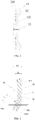
Fig. 1 is a structural schematic diagram of an occluder provided in a first exemplary embodiment of the present application; -
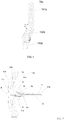
Fig. 2 is a schematic diagram of a locked state of the occluder provided in a first exemplary embodiment of the present application; -
Fig. 3 is a partial structural schematic diagram of locking a locking member and a proximal end bolt head of the occluder inFig. 2 ; -
Fig. 4 is a structural schematic diagram of a locking hole of the occluder inFig. 1 ; -
Fig. 5 is a structural schematic diagram of an occluder of a second exemplary embodiment of the present application; -
Fig. 6 is a structural schematic diagram of a locking member of the occluder inFig. 5 ; -
Fig. 7 is a structural schematic diagram of an occlusion device provided in a third exemplary embodiment of the present application; -
Fig. 8 is a structural schematic diagram of a locking sleeve of the occlusion device inFig. 7 ; -
Fig. 9 is a schematic diagram of the occlusion device, located in a sheath tube, in a third exemplary embodiment of the present application; -
Fig. 10 is a schematic diagram of pushing an occluder inFig. 9 out of the sheath tube; -
Fig. 11 is a schematic diagram of partially releasing the occluder inFig 10 ; -
Fig. 12 is a schematic diagram of releasing, but not locking, the occluder inFig. 11 when the occluder arrives at a defect part; and -
Fig. 13 is a schematic diagram of the occluder inFig. 12 in a locked state. - To understand the technical features, objectives and effects of the present application more clearly, specific implementation modes of the present application are described now in detail in combination with accompanying drawings.
- To describe the structure of the present application more clearly, "distal end" and "proximal end" are used as localizers. The localizers are terms commonly used in the field of interventional medical instruments. The "distal end" refers to the end away from an operator in the surgical procedure, and the "proximal end" refers to the end close to the operator in the surgical procedure. The axial direction refers to a direction parallel to a connecting line between the center of the distal end of a medical instrument and the center of the proximal end of the medical instrument. The radial direction refers to a direction perpendicular to the axial direction.
- In a first exemplary embodiment, referring to
Fig. 1 , anoccluder 100 includes amesh occlusion body 1 defining acavity 103, a proximalend bolt head 2, and a distalend seal head 3. The proximalend bolt head 2 is fixedly connected to the proximal end of theocclusion body 1, and the distalend seal head 3 is fixedly connected to the distal end of theocclusion body 1. Theocclusion body 1 includes afirst occlusion unit 101 and asecond occlusion unit 102 which are both disk-shaped, and the twoocclusion units occluder 100 further includes a lockingmember 14 located in thecavity 103. The distal end of the lockingmember 14 is connected with the distal end of theocclusion body 1. The proximalend bolt head 2 defines a lockinghole 15 communicated with thecavity 103. In an example, the lockinghole 15 is coaxial with the proximalend bolt head 2. - It can be understood that the structure of the
occlusion body 1 is only used as an example, but not intended to limit the present application. Those of ordinary skill in the art can select any proper structure for anocclusion body 1 under the inspiration of the present application. The mesh structure is easy to deform, is convenient for effectively compressing theoccluder 100 into a sheath tune in a delivery process, and is also convenient for deformation into two disk-shaped structures favorable for defect occlusion when the occluder is pushed out of the sheath tube and arrives at a defect part. - The locking
member 14 includes a connectingportion 141 and afirst bending portion 142 connected with the proximal end of the connectingportion 141. A preset bending included angle A is formed between the connectingportion 141 and thefirst bending portion 142. The lockingmember 14 is elastic and may elastically deform under the action of an external force. That is, under the action of the external force, the first bending included angle A between the connectingportion 141 and thefirst bending portion 142 may vary; and after the external force disappears, the first bending included angle A between the connectingportion 141 and thefirst bending portion 142 recovers to the original angle. - The diameter of a circumscribed circle of a projection of the
first bending portion 142 on the cross section perpendicular to a lengthwise direction of thefirst bending portion 142 is less than that of a minimum inscribed circle of the lockinghole 15. In one example, referring toFig. 3 together, in the present embodiment, the lockingmember 14 is of a columnar structure having a circular cross section. At the moment, the outer diameter d of thefirst bending portion 142 is the diameter of the circumscribed circle of the projection of thefirst bending portion 142 on the cross section perpendicular to the lengthwise direction of thefirst bending portion 142. It can be understood that in other embodiments, the lockingmember 14 may be of a structure having an elliptical cross section, a trapezoid cross section or a cross section of other shapes. - Referring to
Fig. 2 and Fig. 3 , in the present embodiment, the lockinghole 15 is a cylindrical hole. The diameter of a maximum inscribed circle of the lockinghole 15 is equal to that of the minimum inscribed circle, and the inner diameter D of the lockinghole 15 is the diameter of its maximum inscribed circle and the diameter of its minimum inscribed circle. The proximal end of thefirst bending portion 142 may be inserted into the lockinghole 15 and passes through the proximal end of the lockinghole 15. The width of a projection of thefirst bending portion 142 on a plane perpendicular to the longitudinal central axis direction of the lockinghole 15 is greater than the diameter of the maximum inscribed circle of the lockinghole 15. The width of the projection refers to a distance between two farthest points on the projection of thefirst bending portion 142 on the plane perpendicular to the longitudinal central axis of the lockinghole 15. In the present embodiment, the width of the projection of thefirst bending portion 142 on the plane perpendicular to the longitudinal central axis direction of the lockinghole 15 is D1. After thefirst bending portion 142 passes through the lockinghole 15, the lockingmember 14 and the lockinghole 15 are locked in the absence of the external force. - It can be understood that in other embodiments, the locking
hole 15 also may be a conical hole, a gourd-shaped hole, a quadrangular hole, and the like, as long as the diameter of the minimum inscribed circle of the lockinghole 15 is greater than that of the circumscribed circle of the projection of thefirst bending portion 142 on the cross section perpendicular to the lengthwise direction of thefirst bending portion 142, and the width of the projection of thefirst bending portion 142 on the plane perpendicular to the longitudinal central axis direction of the lockinghole 15 is greater than the diameter of the maximum inscribed circle of the lockinghole 15. - Further, the
occluder 100 has a natural state and a locked state. In the natural state which is an external force-free state, as shown inFig. 1 , thefirst occlusion unit 101 and thesecond occlusion unit 102 of theoccluder 100 are away from each other, and the proximal end of the lockingmember 14 is not inserted into the lockinghole 15. The outer diameter d of thefirst bending portion 142 of the lockingmember 14 is less than the inner diameter D of the lockinghole 15. In an example, the overall width of the lockingmember 14 is kept consistent. - Referring to
Figs. 1 to 3 together, when moving towards the proximal end under the action of an external force, that is, when changed from the natural state into the locked state as shown inFig. 2 , the lockingmember 14 drives the distal end of theocclusion body 1 to move towards the proximalend bolt head 2. As the outer diameter d of thefirst bending portion 142 is less than the inner diameter D of the lockinghole 15, the proximal end of thefirst bending portion 142 may be inserted into the lockinghole 15. Along with the insertion of the lockingmember 14, a force may be generated between thefirst bending portion 142 of the lockingmember 14 and the inner wall of the lockinghole 15, and thefirst bending portion 142 bends under the pressing action of the inner wall of the lockinghole 15, so that the first bending included angle A is enlarged to allow D1 of the projection of thefirst bending portion 142 on the plane perpendicular to the longitudinal central axis of the lockinghole 15 to be less than or equal to the inner diameter D of the lockinghole 15 and allow thefirst bending portion 142 to be continuously inserted into the lockinghole 15. When the distal end of thefirst bending portion 142 is exposed from the distal end of the lockinghole 15, the force from the inner wall of the lockinghole 15 to thefirst bending portion 142 disappears gradually, and thefirst bending portion 142 gradually recovers its original shape. When the lockingmember 14 continuously moves towards the proximal end, the first bending included angle A is continuously decreased. When the external force pulling the lockingmember 14 to move towards the proximal end disappears, as the width D1 of thefirst bending portion 142 on the plane perpendicular to the longitudinal central axis of the lockinghole 15 is greater than the inner diameter D of the lockinghole 15, the side surface of thefirst bending portion 142 abuts against the proximal end face of the lockinghole 15 to prevent the lockingmember 14 from moving towards the distal end to complete the locking of the lockingmember 14, so that the twoocclusion units - The above-mentioned external force pulling the locking member may be a traction force applied by a doctor (or other party charged with manipulating the device) to the locking
member 14 towards the proximal end. In the locked state, the distance between thefirst occlusion unit 101 and thesecond occlusion unit 102 of theocclusion body 1 is constant (namely the waist height of the occlusion body is constant). - In the present embodiment, to better complete the above-mentioned operation, all the components of the
occluder 100 have some desired or predetermined sizes. For example, theoccluder 100 is delivered into the body by an interventional method, so that the size of the proximalend bolt head 2 of theoccluder 100 may not be too large, which restrains the inner diameter D of the lockinghole 15. Referring toFig. 3 , the inner diameter D of the lockinghole 15 ranges between about 0.5 mm to 3 mm; the first bending included angle A between the connectingportion 141 and thefirst bending portion 142 of the lockingmember 14 ranges between about 120 degrees to 175 degrees; and the length L of thefirst bending portion 142 of the lockingmember 14 ranges between about 0.5 mm to 3 mm. The outer diameters d of the connectingportion 141 and thefirst bending portion 142 are less than the value of the inner diameter D of the lockinghole 15, and the outer diameters d of the connectingportion 141 and thefirst bending portion 142 are equal, and a ratio of the outer diameter d to the inner diameter D of the lockinghole 15 is about 0.5-0.95. A too-small ratio of the outer diameter d of thefirst bending portion 142 to the inner diameter D of the lockinghole 15 may lead to unreliable locking, and a too-large ratio of the outer diameter d of thefirst bending portion 142 to the inner diameter D of the lockinghole 15 may lead to a relatively high difficulty in inserting thefirst bending portion 142 into the lockinghole 15. As the width D1 of the projection of thefirst bending portion 142 on the plane perpendicular to the longitudinal central axis of the lockinghole 15 is greater than the inner diameter D of the lockinghole 15, after thefirst bending portion 142 passes through the lockinghole 15, the connectingportion 141 of the lockingmember 14 may be located in the lockinghole 15 smoothly. In addition, while a heart is beating, theoccluder 100 also may deform in a coordinated manner to adapt to the heart beating. That is, when the heart is beating, the width of the connectingportion 141 is less than the inner diameter D of the lockinghole 15, and the connectingportion 141 still may move towards the proximal end of theoccluder 100, so that thefirst occlusion unit 101 and thesecond occlusion unit 102 of theoccluder 100 still may continuously get close to each other under the action of pressure along with the heart beating, and theoccluder 100 may deform coordinately along with the heart beating. - The locking function of the
occluder 100 is mainly implemented through the cooperation of the lockingmember 14 arranged in thecavity 103 of theocclusion body 1 and the lockinghole 15 formed in the proximalend bolt head 2. The lockingmember 14 may be made of a metal material or a macromolecular material biologically compatible with a human body. The distal end of the lockingmember 14 is connected with the distal end of theocclusion body 1. Under the traction of an external force (such as a pulling force of a traction member), the lockingmember 14 may drive the distal end of theocclusion body 1 to move towards the proximal end. -
Fig. 1 shows the non-locked natural state of theoccluder 100, andFig. 2 shows a state that the lockedoccluder 100 occludes adefect part 18. - The mesh structure of the
occlusion body 1 may be manufactured by adopting a memory alloy material or a macromolecular material in a way of weaving, tubular product cutting, injection molding, or the like. The memory alloy material includes a nickel-titanium alloy, and the macromolecular material is good in biological compatibility. Compared with a metal material, the macromolecular material may avoid problems caused by a release of metal elements in the body, and a material having the good biological compatibility may effectively reduce infection risks of an occluded part. Theocclusion body 1 in the present application may be woven from a degradable macromolecular wire which may be made of a similar material such as PET (Polyethylene Terephthalate), PLA (Poly-L-lactide Acid), PGA (Poly-glycolide), PHA (Poly-hydroxyalkanoate), PDO (Polu-dioxanone) and PCL (Poly-caprolactone). - Referring to
Fig. 1 to Fig. 2 again, the distal end of theocclusion body 1 is further provided with the distalend seal head 3. The lockingmember 14 is connected with the distalend seal head 3. It can be understood that in other embodiments, the distal end of theocclusion body 1 also may be of a seal head-free structure. When anoccluder 100 without a seal head structure at the distal end is adopted, the lockingmember 14 may be directly connected with the distal end of theocclusion body 1. When anocclusion body 1 of a grid structure woven from a weaving wire is adopted, the distalend seal head 3 and the proximalend bolt head 2 may be respectively arranged at the distal end and the proximal end to accommodate and fix the end portions of the weaving wires forming the mesh structure. There are no limitations to the shapes and the structures of the distalend seal head 3 and the proximalend bolt head 2. In the present embodiment, the distalend seal head 3 is a curved body, and the proximalend bolt head 2 is of a columnar structure. - Compared with a traditional memory alloy (such as a nickel-titanium alloy), the macromolecular material has the characteristics of relatively low elastic modulus and relatively small elasticity range, and the memory alloy may possibly have a fatigue failure during long-term use and may not effectively occlude the defect part. It is possible that by the adoption of the above-mentioned two materials, the
occlusion body 1 may not be well kept in its predetermined shape after being set. At the moment, a locking structure is utilized to improve the forming performance of theoccluder 100 in the human body. The present application correspondingly designs a locking structure, including the lockingmember 14 and the lockinghole 15. The locking structure is applicable to locking theocclusion body 1 made of the macromolecular material and is also applicable to locking anoccluder 100 made of other materials. - In the prior art, during implementation of locking and unlocking of two structures, there is a very high requirement on the size accuracy of the locking member, and the accuracy is generally required to be about 1 micron. It is relatively hard for the metal material to reach this accuracy, and it is harder for the macromolecular material to control this size accuracy. In addition, the locking member and the proximal end bolt head which are made of the macromolecular material are exposed to water during the cleaning and are exposed to blood during the operation. In these processes, the water-absorbing swelling property of the macromolecular material or the adsorption of biomolecules in the blood will affect the size accuracy of the macromolecular components and thus affect the locking function, namely a subtle change of the size may lead to difficult implementation of interference fit and may finally result in a surgical failure.
- In an occluder of the present application, the locking process may be completed by the cooperation of the locking member and the proximal end bolt head having the locking hole, the structure is simple and the locking operation is simplified compared to the prior art. The locking member of the present application is elastic, and includes the connecting portion and the first bending portion, and the bending included angle is formed between the connecting portion and the first bending portion. According to the present application, in the processes of locking and unlocking the locking mechanism, it is only utilized to control the width of the projection of the first bending portion on the plane perpendicular to the longitudinal central axis direction of the locking hole to be greater than the diameter of the maximum inscribed circle of the locking hole and control the diameter of the circumscribed circle of the projection of the first bending portion on the cross section perpendicular to the lengthwise direction of the first bending portion to be less than that of the minimum inscribed circle of the locking hole, and the width of the projection of the first bending portion on the plane perpendicular to the longitudinal central axis direction of the locking hole is mainly determined by the bending included angle, so it only needs to control the size of the bending included angle and the diameter of the circumscribed circle of the projection of the first bending portion on the cross section perpendicular to the lengthwise direction of the first bending portion instead of controlling the size accuracy between the locking member and the locking hole of the present application at a micron level. During machining, the bending included angle between the connecting portion and the first bending portion is easy to control, and at the same time, during the design, the locking member is designed to be smaller to reserve a certain size to effectively prevent the locking failure of the occluder resulted from a size change caused by the swelling of the macromolecular material. Therefore, the present application is simple in structure, and the size of the locking member is easy to control, thus facilitating the machining and simplifying a manufacturing process and the locking operation. In addition, the locking member is difficult to fail thanks to its high locking reliability, and furthermore, the locking operation process is reversible, and the locking process and a withdrawing process are simple and feasible.
- Referring to
Fig. 3 , the lockingmember 14 is detachably connected with a pusher or a pushing device, so that one of detachable connection modes may be threaded connection. The proximal end of thefirst bending portion 142 of the lockingmember 14 is configured with a threadedhole 145. In the present embodiment, the threadedhole 145 is coaxial with thefirst bending portion 142, and the coaxial threadedhole 145 may be connected with a pushing mechanism more easily. - It can be understood that in other embodiments, the locking
member 14 also may adopt a hollow tube design. During production, the inner wall of the hollowtubular locking member 14 of a predetermined size is configured with an internal thread, and the lockingmember 14 is bent into a predetermined angle, so as to form the connectingportion 141 and thefirst bending portion 142. The hollowtubular locking member 14 may simplify the machining process and may easily control the coaxiality between the threaded hole and thefirst bending portion 142, so as to allow the lockingmember 14 to be connected with a traction device or the pushing device more easily. - It can be understood that in other embodiments, the proximal end of the locking
member 14 also may be configured with no thread, but the lockingmember 14 also may be detachably connected with the traction device or the pushing device through a fastener. - It can be further understood that the connection between the locking
member 14 and the traction device or the pushing device may be in other connection modes which are not listed one by one here, as long as the lockingmember 14 is detachably connected with the pusher or the pushing device. - Referring to
Fig. 3 again, in order to insert the lockingmember 14 into the lockinghole 15 of the proximalend bolt head 2 more easily, afillet 1421 is added at the proximal end portion of thefirst bending portion 142 of the lockingmember 14. Thefillet 1421 refers to that the proximal end face of thefirst bending portion 142 and the side wall of thefirst bending portion 142 are in arc transition and the outer diameter of the proximal end face is less than that of the side wall of thefirst bending portion 142. Correspondingly, referring toFig. 4 , a hollowtransitional region 16 is arranged at a position, close to the distal end of the lockinghole 15, of the lockinghole 15. The radial length of thetransitional region 16 is gradually increased from the proximal end to the distal end, and thetransitional region 16 is communicated with the lockinghole 15. As thefillet 1421 is arranged at the proximal end portion of thefirst bending portion 142, thefirst bending portion 142 is inserted into the conicaltransitional region 16 having a relatively large opening more easily, so as to enter the lockinghole 15. - The whole
transitional region 16 may be of a similar conical shape or horn shape. The radial length of the proximal end of thetransitional region 16 is less than that of the distal end. It can be understood that in other embodiments, thetransitional region 16 also may be of a similarly trapezoid shape. Or, in still other embodiments, when a difference between the radial lengths of the lockingmember 14 and the lockinghole 15 is relatively large, no transitional region is set. - It can be further understood that in other embodiments, the edge of the proximal end of the
transitional region 16 is configured with an arc-shapedchamfer 161 which may cooperate with thefillet 1421 on the lockingmember 14. When the lockingmember 14 moves towards the proximal end under the traction of an external force, the arc-shapedchamfer 161 may avoid the edge of the proximal end of thetransitional region 16 from abutting against the proximal end of the lockingmember 14, so as to allow the lockingmember 14 to be inserted into the lockinghole 15 more easily. - In a second exemplary embodiment, referring to
Fig. 5 , the present application further shows anoccluder 100a. Theoccluder 100a is substantially similar tooccluder 100 shown by the first embodiment, and a difference lies in that in this embodiment, a lockingmember 14a of the occluder 100a includes a connectingportion 141a, afirst bending portion 142a and asecond bending portion 143a. The proximal end of the connectingportion 141a is connected with the distal end of thefirst bending portion 142a, and the proximal end of thefirst bending portion 142a is connected with the distal end of thesecond bending portion 143a. - Referring to
Fig. 6 as well, a first bending included angle A1 is formed between thefirst bending portion 142a and the connectingportion 141a, and a second bending included angle A2 is formed between thefirst bending portion 142a and thesecond bending portion 143a. In an example, the first bending included angle A1 and the second bending included angle A2 are equal, in order to ensure that the connectingportion 141a and thesecond bending portion 143a are kept in a parallel state, thereby keeping an acting direction of a force of the lockingmember 14a under the pulling of an external force unchanged, and facilitating the connection of the lockingmember 14a and a traction device; and, in addition, the proximal end of the lockingmember 14a may be inserted into alocking hole 15a more easily. - It can be understood that in other embodiments, the first bending angle A1 also may be different from the second bending angle A2 as long as the width of a projection of a hole formed by the
first bending portion 142a and thesecond bending portion 143a on a plane perpendicular to the longitudinal central axis direction of thelocking hole 15a is greater than the inner diameter of thelocking hole 15a. - When the first bending angle A1 and the second bending angle A2 are not equal, a projection of the
second bending portion 143a on the plane perpendicular to the longitudinal central axis direction of thelocking hole 15a may partially or all fall into a projection of thefirst bending portion 142a on the plane perpendicular to the longitudinal central axis direction of thelocking hole 15a. When the first bending angle A1 and the second bending angle A2 are equal, the projection of thesecond bending portion 143a on the plane perpendicular to the longitudinal central axis direction of thelocking hole 15a may all fall into the projection of thefirst bending portion 142a on the plane perpendicular to the longitudinal central axis direction of thelocking hole 15a. - It can be understood that in other embodiments, the locking member also may include a number of bending portions. The shape of each bending portion is similar to that of the first bending portion or the second bending portion. The bending portions are connected end to end. The proximal ends of the end-to-end bending portions are connected with the distal end of the connecting portion, and a first bending included angle is formed between the connecting portion and the bending portion closest to the connecting portion. The diameter of a circumscribed circle of a projection of each bending portion on a cross section perpendicular to a lengthwise direction of the bending portion is less than that of a minimum inscribed circle of the locking hole. The width of a projection of a whole formed by the multiple end-to-end bending portions on the plane perpendicular to the longitudinal central axis direction of the locking hole is greater than the diameter of a maximum inscribed circle of the locking hole. The width of a projection of the bending portion, closest to the connecting portion, on the plane perpendicular to the longitudinal central axis direction of the locking hole is greater than the diameter of the maximum inscribed circle of the locking hole.
- As shown in
Fig. 7 , a third exemplary embodiment of the present application further shows anocclusion device 300b. By taking an occluder shown by a second exemplary embodiment, for example, theocclusion device 300b of the present embodiment includes anoccluder 100b, ahollow delivery mechanism 200b at least configured with an opening in the distal end, a lockingsleeve 6b for connecting thedelivery mechanism 200b with theoccluder 100b, and atraction member 4b movably accommodated in thedelivery mechanism 200b. The distal end of thetraction member 4b penetrates the distal end of thedelivery mechanism 200b and may be detachably connected with the proximal end of the lockingmember 14b in a cavity. Thetraction member 4b may pull the lockingmember 14b under the action of an external force applied by an operator, such as a doctor, towards the proximal end to drive the distal end of theoccluder 100b to move towards the proximal end till the proximal end of the lockingmember 14b passes through thelocking hole 15b and abuts against the end face of the proximalend bolt head 2b to lock theoccluder 100b. - The structure of the
occluder 100b is completely described in a second exemplary embodiment above, so, for the sake of brevity, no more details will be described here. - Referring to
Fig. 8 as well, the lockingsleeve 6b is used for connecting thedelivery mechanism 200b with the proximalend bolt head 2b of theoccluder 100b, and includes a first connectinghead 61b and a second connectinghead 62b which are connected with each other, and the proximal end of the first connectinghead 61b is connected with the distal end of the second connectinghead 62b. The first connectinghead 61b and the second connectinghead 62b are both hollow and communicate with each other. On the whole, the first connectinghead 61b and the second connectinghead 62b are of barrel shapes. The inner diameter of the first connectinghead 61b is greater than that of the second connectinghead 62b. The inner surface of the first connectinghead 61b is configured with aninternal thread 611b matched with the external thread of the proximalend bolt head 2b of theoccluder 100b. During connection, the second connectinghead 62b is arranged at the distal end of thedelivery mechanism 200b in a sleeving manner and the first connectinghead 61b is arranged on the proximalend bolt head 2b of theoccluder 100b in a sleeving manner through laser welding at first; and the lockingsleeve 6b is fastened and connected with the proximalend bolt head 2b by screwing thedelivery mechanism 200b. - In the
occluder 100b, a locking process is completed by cooperation of the lockingmember 14b and the proximalend bolt head 2b having the lockinghole 15b. The lockingmember 14b is of a rod-like structure and similar structures, and has a bending angle, so that a locking structure is simple; and no complicated mechanical structure and no cooperation relation are needed, so that a manufacturing process and the locking operation are simplified. Furthermore, after passing through thelocking hole 15b and being exposed from the lockinghole 15b through elastic deformation, the proximal end of the lockingmember 14b may abut against the proximal end portion of thelocking hole 15b, and the locking is high in reliability and has a low failure rate. -
Figs. 9 to 13 show the cooperation of theoccluder 100b and thedelivery mechanism 200b to implement delivery, release, and locking processes. First, theoccluder 100b and thedelivery mechanism 200b are connected together through the lockingsleeve 6b, and the lockingsleeve 6b and the proximalend bolt head 2b are in threaded connection and collected in asheath tube 30b. The distal end of thetraction member 4b and the lockingmember 14b are in threaded connection. When theoccluder 100b is collected into thesheath tube 30b, thetraction member 4b is set along an axial direction of thesheath tube 30b without restraining the free deformation of theoccluder 100b. - The
occluder 100b is pushed to aheart defect part 18b, and thetraction member 4b is pulled towards the proximal end to allow the two disk-shaped structures of theoccluder 100b to be closed up gradually to form an "I" shape and implement the state as shown inFig. 7 . The specific process is as follows:
Under the traction of the traction member 4b, the locking member 14b abuts against the locking hole 15b of the proximal end bolt head 2b; as a force exists between the inner wall of the proximal end bolt head 2b and the second bending portion 143b of the locking member 14b, the second bending portion 143b and the first bending portion 142b of the locking member 14b may apply a force to the inner wall of the locking hole 15b along with the insertion of the locking member 14b into the locking hole 15b; the first bending portion 142b and the second bending portion 143b bend under the pressing action of the inner wall of the locking hole 15b, so that the first bending included angle A1 and the second bending included angle A2 are enlarged to allow the widths of the projections of the first bending portion 142b and the second bending portion 143b on the plane perpendicular to the longitudinal central axis direction of the locking hole 15b to be less than the inner diameter of the locking hole 15b and allow the locking member 14b to be continuously inserted into the locking hole 15b; when the distal end of the locking member 14b is exposed from the distal end of the locking hole 15b, the force applied by the inner wall of the locking hole 15b to the first bending portion 142b and the second bending portion 143b disappears gradually, and the first bending portion 142b and the second bending portion 143b gradually recover original shapes; and the width of the projection of the locking member 14b on the plane perpendicular to the longitudinal central axis direction of the locking hole 15b is greater than the inner diameter of the locking hole 15b, and the side surface of the first bending portion 142b abuts against the proximal end face of the locking hole 15b, so that the locking member 14b may not move towards the distal end to complete the locking of the occluder 100b. - The
traction member 4b is rotated to relieve the connection with the lockingmember 14b; after the connection is relieved, thetraction member 4b is withdrawn; adelivery tube 5b is rotated to relieve the connection between the lockingsleeve 6b and the proximalend bolt head 2b; and finally, thedelivery tube 5b is pulled back to complete removal. - As the locking
member 14b passes through thelocking hole 15b through the elastic deformation, the locking process is reversible. Theoccluder 100b further has an unlocked state. Before the connection between thetraction member 4b and the lockingmember 14b is not relieved, thetraction member 4b may be axially operated to move towards the distal end till the lockingmember 14b returns back into the cavity of theoccluder 100b through thelocking hole 15b, then theoccluder 100b returns from the state inFig. 13 to the state inFig. 11 , and the unlocking is realized. After theoccluder 100b returns to the state inFig. 11 , thedelivery tube 5b may be further pulled towards the proximal end to withdraw theoccluder 100b into thesheath tube 30b to implement the withdrawal of theoccluder 100b. - All the technical features of the above embodiments may be combined, as desired. To simplify the descriptions, not all possible combinations of all the technical features in the above-mentioned embodiments are described. However, the combinations of these technical features shall all fall within the scope in the present application in case of no contradictions.
- The above embodiments only express several implementation modes of the present application, and their descriptions are relatively specific and detailed, but should not be understood as limitations to the application thereby. It should be noted that persons of ordinary skill in the art can also make variety of changes and improvements without departing from the conception of the present application, and these changes and improvements fall within the protection scope of the present application
Claims (15)
- An occluder, comprising:a mesh occlusion body defining a cavity and a proximal end bolt head, and the proximal end bolt head defines a locking hole in communication with the cavity;the occluder further comprises a locking member located in the cavity;the distal end of the locking member is connected with the distal end of the occlusion body;the locking member is an elastic member, and comprises a connecting portion connected with the occlusion body and a first bending portion connected with the proximal end of the connecting portion;a joint of the connecting portion and the first bending portion defines a first bending included angle;the diameter of a circumscribed circle of a projection of the first bending portion on a cross section perpendicular to the lengthwise direction of the first bending portion is less than that of a minimum inscribed circle of the locking hole; andthe width of a projection of the first bending portion on a plane perpendicular to the longitudinal central axis direction of the locking hole is greater than the diameter of a maximum inscribed circle of the locking hole.
- An occluder, comprising:a mesh occlusion body defining a cavity and a proximal end bolt head, and the proximal end bolt head defines a locking hole communicated with the cavity;the occluder further comprises a locking member located in the cavity;the distal end of the locking member is connected with the distal end of the occlusion body;the locking member is an elastic member, and comprises a connecting portion connected with the occlusion body and a plurality of bending portions connected with one another end to end;the proximal ends of the end-to-end bending portions are connected with the proximal end of the connecting portion, and a first bending included angle is formed between the connecting portion and the bending portion closest to the connecting portion;the diameter of a circumscribed circle of a projection of each bending portion on a cross section perpendicular to the lengthwise direction of the bending portion is less than that of a minimum inscribed circle of the locking hole; andthe width of a projection of a whole, formed by the multiple end-to-end bending portions, on a plane perpendicular to the longitudinal central axis direction of the locking hole is greater than the diameter of a maximum inscribed circle of the locking hole.
- The occluder according to claim 2, wherein the width of a projection of the bending portion, proximate to the connecting portion, on the plane perpendicular to the longitudinal central axis direction of the locking hole, is greater than the diameter of the maximum inscribed circle of the locking hole.
- The occluder according to claim 3, wherein in end-to-end bending portions, the bending portion closest to the connecting portion is a first bending portion, and the bending portion closest to the first bending portion is a second bending portion; and
a second bending included angle is formed between the second bending portion and the first bending portion, and the first bending included angle is equal to the second bending included angle. - The occluder according to any one of claims 1 to 4, wherein the first bending included angle ranges from 120 degrees to 175 degrees.
- The occluder according to any one of claims 1 to 4, wherein the proximal end portion of the locking member is configured with a threaded hole in communication with an outside.
- The occluder according to claim 6, wherein the threaded hole is coaxial with the bending portion.
- The occluder according to claim 6, wherein the locking member is a hollow tubular structure, and the threaded hole is in communication with an inner cavity of the locking member.
- The occluder according to any one of claims 1 to 4, wherein the proximal end portion of the locking member is configured with a fillet.
- The occluder according to any one of claims 1 to 4, wherein the proximal end bolt head is configured with an external thread.
- The occluder according to any one of claims 1 to 4, wherein the distal end portion of the locking hole is configured with a transitional region, and the aperture of the distal end of the transitional region is greater than that of the proximal end of the transitional region.
- The occluder according to any one of claims 1 to 4, wherein the occlusion body is made of a macromolecular material biologically compatible.
- An occlusion device, comprising:
an occluder comprising a mesh occlusion body defining a cavity and a proximal end bolt head, and the proximal end bolt head defines a locking hole in communication with the cavity;the occluder further comprises a locking member located in the cavity;the distal end of the locking member is connected with the distal end of the occlusion body;the locking member is an elastic member, and comprises a connecting portion connected with the occlusion body and a first bending portion connected with the proximal end of the connecting portion;a joint of the connecting portion and the first bending portion defines a first bending included angle;the diameter of a circumscribed circle of a projection of the first bending portion on a cross section perpendicular to the lengthwise direction of the first bending portion is less than that of a minimum inscribed circle of the locking hole; andthe width of a projection of the first bending portion on a plane perpendicular to the longitudinal central axis direction of the locking hole is greater than the diameter of a maximum inscribed circle of the locking hole; andthe occlusion device further comprising a hollow delivery mechanism at least defining an opening in the distal end, a locking sleeve for connecting the delivery mechanism with the occluder, and a traction member movably accommodated in the delivery mechanism, wherein the distal end of the traction member penetrates the distal end of the delivery mechanism and then is detachably connected with the proximal end of the bending portion of the locking member. - The occlusion device according to claim 13, wherein the proximal end portion of the locking member is configured with a threaded hole in communication with an outside, and the distal end of the traction member is configured with an external thread matched with the threaded hole of the locking member.
- The occlusion device according to claim 14, wherein the proximal end bolt head is configured with an external thread; the locking sleeve comprises a hollow first connecting head and a second connecting head connected with the proximal end of the first connecting head; the first connecting head is configured with an internal thread matched with the external thread of the proximal end bolt head; and the second connecting head is arranged on the outer wall of the delivery mechanism in a sleeving manner.
Applications Claiming Priority (2)
| Application Number | Priority Date | Filing Date | Title |
|---|---|---|---|
| CN201710226942.5A CN108685599B (en) | 2017-04-06 | 2017-04-06 | Occluder and occlusion device |
| PCT/CN2018/078276 WO2018184438A1 (en) | 2017-04-06 | 2018-03-07 | Occluder and occlusion device |
Publications (2)
| Publication Number | Publication Date |
|---|---|
| EP3607887A1 true EP3607887A1 (en) | 2020-02-12 |
| EP3607887A4 EP3607887A4 (en) | 2021-01-13 |
Family
ID=63712053
Family Applications (1)
| Application Number | Title | Priority Date | Filing Date |
|---|---|---|---|
| EP18781056.9A Pending EP3607887A4 (en) | 2017-04-06 | 2018-03-07 | Occluder and occlusion device |
Country Status (4)
| Country | Link |
|---|---|
| US (1) | US11311281B2 (en) |
| EP (1) | EP3607887A4 (en) |
| CN (1) | CN108685599B (en) |
| WO (1) | WO2018184438A1 (en) |
Families Citing this family (10)
| Publication number | Priority date | Publication date | Assignee | Title |
|---|---|---|---|---|
| CN111803167B (en) * | 2019-04-11 | 2025-08-15 | 杭州唯强医疗科技有限公司 | Plugging device, plugging device locking system and locking method |
| WO2020207484A1 (en) * | 2019-04-11 | 2020-10-15 | 杭州唯强医疗科技有限公司 | Occluder, occluder fastening system and fastening method |
| US20210236102A1 (en) * | 2020-02-03 | 2021-08-05 | St. Jude Medical, Cardiology Division, Inc. | Occluder locking mechanisms |
| CN112401947B (en) * | 2020-11-24 | 2023-08-08 | 李建朝 | Spherical structure plugging device for extracardiac operation and application method thereof |
| CN114642466B (en) * | 2020-12-17 | 2024-04-02 | 先健科技(深圳)有限公司 | Conveying device and conveying system |
| CN114587472B (en) * | 2022-02-25 | 2024-05-28 | 上海形状记忆合金材料有限公司 | An occluder |
| CN116807529A (en) * | 2022-03-22 | 2023-09-29 | 上海微创医疗器械(集团)有限公司 | Plugging device |
| CN116138819B (en) * | 2023-04-04 | 2023-07-28 | 杭州唯强医疗科技有限公司 | Closure devices and closure systems |
| CN120514432B (en) * | 2025-07-22 | 2025-09-23 | 上海形状记忆合金材料有限公司 | Plugging device assembly with unlocking function |
| CN121337409B (en) * | 2025-12-19 | 2026-02-13 | 先健科技(深圳)有限公司 | Plugging device and plugging system |
Family Cites Families (21)
| Publication number | Priority date | Publication date | Assignee | Title |
|---|---|---|---|---|
| DE69102515T2 (en) * | 1990-04-02 | 1994-10-20 | Kanji Inoue | DEVICE FOR CLOSING A SHUTTER OPENING BY MEANS OF A NON-OPERATIONAL METHOD. |
| ES2173073T3 (en) * | 2000-11-03 | 2002-10-16 | Radi Medical Systems | DEVICE OF SUTURE AND CLOSURE OF WOUNDS. |
| CA2563298A1 (en) * | 2004-05-07 | 2005-11-24 | Nmt Medical, Inc. | Catching mechanisms for tubular septal occluder |
| EP1827247B8 (en) | 2004-09-24 | 2020-05-06 | W.L. Gore & Associates, Inc. | Occluder device double securement system for delivery/recovery of such occluder device |
| US20070167981A1 (en) * | 2005-12-22 | 2007-07-19 | Nmt Medical, Inc. | Catch members for occluder devices |
| US8162974B2 (en) * | 2006-02-02 | 2012-04-24 | Boston Scientific Scimed, Inc. | Occlusion apparatus, system, and method |
| JP2009532125A (en) * | 2006-03-31 | 2009-09-10 | エヌエムティー メディカル, インコーポレイティッド | Deformable flap catch mechanism for occluder equipment |
| CH701269A1 (en) * | 2009-06-10 | 2010-12-15 | Carag Ag | Occluder. |
| JP6240604B2 (en) * | 2011-08-19 | 2017-11-29 | インセプタス メディカル リミテッド ライアビリティ カンパニー | Expandable occlusion device and method |
| CN102895047A (en) * | 2012-09-17 | 2013-01-30 | 邢泉生 | Plugging device for perime membrane ventricular sepetal defect and plugging device assembly |
| CN102895046B (en) * | 2012-09-17 | 2016-04-06 | 邢泉生 | A kind of dry lower or two arterial valve mo(u)ld bottom half ventricular septal defect |
| CN202875400U (en) * | 2012-09-17 | 2013-04-17 | 邢泉生 | Membrane ventricular septal defect plugging device and plugging device set |
| CN203576563U (en) * | 2013-12-06 | 2014-05-07 | 先健科技(深圳)有限公司 | Plugging device with locking mechanism |
| CN103654883B (en) * | 2013-12-06 | 2017-01-04 | 深圳市先健生物材料技术有限公司 | The stopper of with locking mechanism |
| WO2015127013A1 (en) * | 2014-02-24 | 2015-08-27 | Boston Scientific Scimed, Inc. | Hemostasis devices |
| JP6640829B2 (en) * | 2014-03-27 | 2020-02-05 | ラフィー・ナッサーRAFIEE, Nasser | Apparatus and method for closure of a transvascular or transventricular access port |
| US9808230B2 (en) * | 2014-06-06 | 2017-11-07 | W. L. Gore & Associates, Inc. | Sealing device and delivery system |
| CN104116574A (en) * | 2014-07-04 | 2014-10-29 | 先健科技(深圳)有限公司 | Plug and plugging device |
| CN204181658U (en) * | 2014-08-25 | 2015-03-04 | 先健科技(深圳)有限公司 | Heart defect amplatzer |
| CN205251616U (en) * | 2015-11-27 | 2016-05-25 | 先健科技(深圳)有限公司 | Can absorb plugging device |
| CN207785198U (en) * | 2017-04-06 | 2018-08-31 | 先健科技(深圳)有限公司 | Plugging device and plugging device |
-
2017
- 2017-04-06 CN CN201710226942.5A patent/CN108685599B/en active Active
-
2018
- 2018-03-07 WO PCT/CN2018/078276 patent/WO2018184438A1/en not_active Ceased
- 2018-03-07 US US16/493,985 patent/US11311281B2/en active Active
- 2018-03-07 EP EP18781056.9A patent/EP3607887A4/en active Pending
Also Published As
| Publication number | Publication date |
|---|---|
| US20200121306A1 (en) | 2020-04-23 |
| WO2018184438A1 (en) | 2018-10-11 |
| CN108685599A (en) | 2018-10-23 |
| CN108685599B (en) | 2020-07-17 |
| EP3607887A4 (en) | 2021-01-13 |
| US11311281B2 (en) | 2022-04-26 |
Similar Documents
| Publication | Publication Date | Title |
|---|---|---|
| US11311281B2 (en) | Occluder and occlusion device | |
| US10314727B2 (en) | Occluder and occlusion device | |
| CN112998772B (en) | Interventional defect suture device | |
| EP1487357B1 (en) | Coupling system useful in placement of implants | |
| WO2003022344A2 (en) | Flexible delivery system | |
| EP3342354A1 (en) | Handle assembly for a left atrial appendage occlusion device | |
| CN111803166B (en) | Occluder and occluder locking system | |
| BRPI0618119A2 (en) | Coupling devices, release and methods for mounting and use | |
| JP4960257B2 (en) | Delivery system | |
| CN103654883A (en) | Plugging device with locking mechanism | |
| CN113286550B (en) | Plugging device insertion system | |
| CN106923872B (en) | Plugging device, conveyer and plugging system | |
| CN112773448B (en) | Medical instrument implant conveying device | |
| CN207785198U (en) | Plugging device and plugging device | |
| CN203576563U (en) | Plugging device with locking mechanism | |
| CN109247965B (en) | Suturing device | |
| CN112790808B (en) | Medical device post-implantation release device | |
| CN109173027A (en) | A kind of disposable remote-injection syringe of Microendoscopic | |
| CN112998771B (en) | Plugging system | |
| CN116096324A (en) | Device for implanting a medical implant into a human or animal body | |
| CN204133533U (en) | stopper and plugging device | |
| WO2020136826A1 (en) | Medical device and method of installing medical device | |
| CN112998796B (en) | Conveying device | |
| CN105899151B (en) | System for connecting medical implants to insertion devices | |
| CN215688186U (en) | Implantable device delivery system and its connection structure |
Legal Events
| Date | Code | Title | Description |
|---|---|---|---|
| STAA | Information on the status of an ep patent application or granted ep patent |
Free format text: STATUS: THE INTERNATIONAL PUBLICATION HAS BEEN MADE |
|
| PUAI | Public reference made under article 153(3) epc to a published international application that has entered the european phase |
Free format text: ORIGINAL CODE: 0009012 |
|
| STAA | Information on the status of an ep patent application or granted ep patent |
Free format text: STATUS: REQUEST FOR EXAMINATION WAS MADE |
|
| 17P | Request for examination filed |
Effective date: 20191029 |
|
| AK | Designated contracting states |
Kind code of ref document: A1 Designated state(s): AL AT BE BG CH CY CZ DE DK EE ES FI FR GB GR HR HU IE IS IT LI LT LU LV MC MK MT NL NO PL PT RO RS SE SI SK SM TR |
|
| AX | Request for extension of the european patent |
Extension state: BA ME |
|
| DAV | Request for validation of the european patent (deleted) | ||
| DAX | Request for extension of the european patent (deleted) | ||
| A4 | Supplementary search report drawn up and despatched |
Effective date: 20201210 |
|
| RIC1 | Information provided on ipc code assigned before grant |
Ipc: A61B 17/00 20060101AFI20201204BHEP |
|
| STAA | Information on the status of an ep patent application or granted ep patent |
Free format text: STATUS: EXAMINATION IS IN PROGRESS |
|
| 17Q | First examination report despatched |
Effective date: 20240614 |
|
| 17Q | First examination report despatched |
Effective date: 20240625 |