EP3607838A1 - Unit and method for measuring the pressure drop in a smoking article - Google Patents
Unit and method for measuring the pressure drop in a smoking article Download PDFInfo
- Publication number
- EP3607838A1 EP3607838A1 EP19183769.9A EP19183769A EP3607838A1 EP 3607838 A1 EP3607838 A1 EP 3607838A1 EP 19183769 A EP19183769 A EP 19183769A EP 3607838 A1 EP3607838 A1 EP 3607838A1
- Authority
- EP
- European Patent Office
- Prior art keywords
- slot
- measuring
- article
- air
- loading slot
- Prior art date
- Legal status (The legal status is an assumption and is not a legal conclusion. Google has not performed a legal analysis and makes no representation as to the accuracy of the status listed.)
- Granted
Links
Images

Classifications
-
- A—HUMAN NECESSITIES
- A24—TOBACCO; CIGARS; CIGARETTES; SIMULATED SMOKING DEVICES; SMOKERS' REQUISITES
- A24C—MACHINES FOR MAKING CIGARS OR CIGARETTES
- A24C5/00—Making cigarettes; Making tipping materials for, or attaching filters or mouthpieces to, cigars or cigarettes
- A24C5/32—Separating, ordering, counting or examining cigarettes; Regulating the feeding of tobacco according to rod or cigarette condition
- A24C5/34—Examining cigarettes or the rod, e.g. for regulating the feeding of tobacco; Removing defective cigarettes
- A24C5/3418—Examining cigarettes or the rod, e.g. for regulating the feeding of tobacco; Removing defective cigarettes by pneumatic means
Definitions
- This invention relates to a unit and a method for measuring the pressure drop in a smoking article.
- king article is used herein to denote any rod-shaped article for the tobacco industry, defining a finished product, such as a cigarette, for example, or a semi-product (for example: a filter segment, a tobacco segment, a composite segment or a piece of a multisegment product).
- the cigarette may be a traditional cigarette which can be smoked by burning the end of the tobacco segment defining the active portion, or inhaled by heating but not burning an active portion.
- the active portion may be a cigarette segment comprising traditional tobacco or it may be an aerosol-generating element, that is, a product containing heat-not-burn type tobacco.
- cigarettes In order to be correctly smokable, cigarettes must be easy to inhale and draw pressure must be such that inhalation is smooth and not excessively intense.
- cigarettes are therefore subjected to specific tests to make certain that the pressure drop within the smoking articles falls within specified ranges of acceptability.
- Measurement is performed typically in the machine while the articles move transversely along their feed path on conveyors.
- the smoking articles disposed inside suction housing seats round the periphery of a transfer drum are made to pass by a detection device located at a fixed position on the drum itself.
- each article moves past the detection device in such a way that the end of the article is aligned with an angular loading slot of the detection device which extends along a circular arc and through which a predetermined amount of air is injected.
- This solution is described, for example, in DE3341686 (slots 24 and 31) or US3418844 (slots 96-112). More specifically, the angular extent of the loading slot is smaller than the angular distance between two consecutive smoking articles to allow only one smoking article at a time to be loaded and hence tested.
- a pressure sensor of the detection device measures the RTD value.
- the article is thus loaded with air for a loading time corresponding to the time taken by the article to travel in front of the angular loading slot.
- the higher the RTD the longer the time needed for the pressure to be stabilized and thus, for smoking articles with high RTD, air must be injected for a longer length of time.
- the higher the article production speed that is, the higher the drum rotation speed the less the time available for supplying the air, since the articles are tested while in motion.
- the purpose of this invention is to provide a unit and a method for measuring the pressure drop in a smoking article to allow increasing the maximum measurable RTD value.
- this invention has for an aim to increase the length of time available for injecting air through the smoking articles without reducing the production speed.
- the maximum measurable RTD value is thus increased, making it possible to measure a wide range of smoking articles.
- this invention provides a unit for measuring the pressure drop in a smoking article, comprising:
- the measuring device comprises at least two air loading slots connected or connectable to respective, distinct compressed air sources and the connecting means are configured to alternately connect consecutive housing seats to different air loading slots.
- This invention also provides a method for measuring the pressure drop in a smoking article, comprising the following steps:
- the measuring device comprises two air loading slots connected or connectable to distinct compressed air sources and the step of measuring the value of pressure drop of each article is performed by alternately connecting the ends of consecutive articles to different air loading slots.
- unit 1 denotes in its entirety a unit for measuring the pressure drop in a smoking article, hereinafter referred to simply as unit 1.
- the unit 1 comprises a conveyor 2 comprising a plurality of housing seats 3, preferably suction seats, configured to receive and transversely feed a plurality of rod-shaped smoking articles 100 along a feed path P.
- Figures 1 and 2 show only one article 100.
- the unit 1 then comprises a fixed measuring device 4 disposed on the feed path P and configured to measure a value of pressure drop in each article 100.
- the measuring device 4 comprises at least one air loading slot 5a, 5b connected or connectable to a compressed air source 6a, 6b.
- the unit also comprises connecting means 7 disposed on the conveyor 2 and configured to connect at least one air loading slot 5a, 5b sequentially to one of the housing seats 3 in order to feed an air flow to the articles 100.
- the measuring device 4 comprises at least two air loading slots 5a, 5b connected or connectable to respective, distinct compressed air sources 6a, 6b and the connecting means 7 are configured to alternately connect consecutive housing seats 3 to different air loading slots 5a, 5b.
- a first article 100a is adapted to be loaded with a first air flow from the compressed air source 6a through the air loading slot 5a
- a second article 100b is adapted to be loaded with a second air flow from the compressed air source 6b through the air loading slot 5b.
- connecting the articles 100 selectively to alternately different air loading slots 5a, 5b allows making longer air loading slots 5a, 5b, preferably longer than the centre distance between one article 100 and the next without the loading slot 5a, 5b loading more than one article 100 at a time.
- loading slots 5a, 5b whose length is such as to allow obtaining a true measurement of the pressure drop of articles having high values of pressure drop (or resistance to draw, RTD): for example, higher than 200 mmH2O.
- the loading slots 5a, 5b are at a fixed position on the measuring device 4, whilst the connecting means 7 formed on the conveyor are movable along the feed path P together with the articles 100.
- the unit 1 is thus advantageously suitable for easy installation in any machine for making smoking articles 100 in order to efficiently measure the pressure drop values in the articles 100.
- the conveyor 2 is preferably a drum which rotates about an axis of rotation X and has, for each housing seat 3, at least one supporting element 3' for an end portion of an article 100 housed in the housing seat 3.
- the supporting elements 3' are advantageously configured to make a sealed compressed air connection with the compressed air sources 6 in order to obtain a correct measurement.
- the supporting element 3' is associated with the connecting means 7 and the feed path P is a circular path.
- the supporting elements 3' engage the ends of the articles 100 only at a measuring zone M located at the measuring device 4 to allow measuring operations to be carried out.
- the measuring zone M is engaged by means of supporting elements 3' which are fixed to the drum 2 at external inclined discs 2' that are configured to travel along a trajectory lying in a plane transverse to the axis of rotation X of the drum 2.
- the supporting elements 3' might be movable towards and away from the articles 100 along the longitudinal axes thereof so as to selectively engage the articles 100 at the measuring zone M.
- the two loading slots 5a, 5b extend along respective directions of extension parallel to the feed path P of the articles 100 and run alongside each other in a direction perpendicular to the feed path P. More specifically, as shown in the accompanying drawings, therefore, the two loading slots 5a, 5b extend along arcuate directions.
- the connecting means 7 preferably comprise, for each housing seat 3, a respective connecting slot 7a, 7b configured to pneumatically connect each article 100a, 100b to a respective air loading slot 5a, 5b.
- the connecting slots 7a, 7b are disposed in at least two alternate sets in such a way that consecutive housing seats 3a, 3b correspond to connecting slots 7a, 7b of distinct sets configured to be connected to different air loading slots 5a, 5b.
- a first article 100a disposed in a first housing seat 3a with which a first connecting slot 7a is associated, is adapted to be loaded with a first air flow from the compressed air source 6a through a first air loading slot 5a
- a second article 100b disposed in a second housing seat 3b (downstream of the first housing seat 3a) with which a second connecting slot 7b is associated, is adapted to be loaded with a second air flow from the compressed air source 6b through a second air loading slot 5b.
- the connecting slots 7a, 7b extend between the respective article 100a, 100b and the respective air loading slot 5a, 5b along respective directions of extension transverse, preferably perpendicular, to the feed path P.
- the measuring device 4 comprises, for each air loading slot 5a, 5b, a respective measuring slot 8a, 8b which is juxtaposed with the respective air loading slot 5a, 5b.
- each measuring slot 8a, 8b there is a pressure sensor configured to measure a value of pressure drop associated with a respective article 100a, 100b. More specifically, each measuring slot 8a, 8b is placed in fluid communication with the respective air loading slot 5a, 5b by the connecting means 7.
- the air is loaded into the articles 100 through the loading slots 5a, 5b and measurement is performed through the measuring slots 8a, 8b.
- the measuring slots 8a, 8b extend along respective directions of extension parallel to the feed path P of the articles 100.
- the measuring slots 8a, 8b are shorter in length, measured parallel to the feed path P, than the loading slots 5a, 5b.
- the air loading slots 5a, 5b are interposed between the measuring slots 8a, 8b relative to a direction transverse to the feed path P.
- the measuring slot 8a, 8b, the respective air loading slot 5a, 5b and the respective article 100a, 100b to be measured are placed in mutual fluid communication simultaneously by the connecting means 7.
- the operating stretch just mentioned coincides with the length of the measuring slot 8a, 8b.
- each measuring slot 8a, 8b preferably at least partly overlaps the respective air loading slot 5a, 5b along the feed path P and, still more preferably, overlaps only an end portion of the respective air loading slot 5a, 5b along the feed path P so that the pressure is measured only when the article 100 is in communication with that end portion of the of the air loading slot 5a, 5b.
- the end portion of the air loading slot 5a, 5b referred to above extends for a length that is approximately half the length of the air loading slot 5a, 5b itself.
- the conveyor 2 preferably comprises, for each housing seat 3a, 3b, a respective vent 9a, 9b configured to intercept a respective measuring slot 8a, 8b and to relieve the pressure in the measuring slot 8a, 8b.
- the vents 9a, 9b are disposed on the conveyor 3 in at least two alternate sets in such a way that consecutive vents 9a, 9b intercept different measuring slots 8a, 8b.
- vents 9a, 9b and the connecting slots 7a, 7b are thus disposed alternately on the conveyor 3 at each housing seat 3a, 3b along the feed path P.
- the respective vent 9a, 9b is disposed on the side opposite to the respective connecting slot 7a, 7b so that when the connecting slot 7a, 7b associated with the housing seat 3a, 3b is in communication with a respective measuring slot 8a, 8b, the respective vent 9a, 9b is in communication with the other measuring slot 8a, 8b.
- each housing seat 3a, 3b there is a connecting slot 7a, 7b on a first side and a vent 9a, 9b on a second side and for the next housing seat 3a, 3b, the first and second sides are reversed.
- each vent 9a, 9b is aligned with the respective connecting slot 7a, 7b transversely to the feed path P and, still more preferably, aligned along the direction of extension of the connecting slot 7a, 7b.
- the measuring device 4 advantageously comprises, for each air loading slot 5a, 5b, a respective air pre-loading slot 10a, 10b disposed upstream of the air loading slot 5a, 5b relative to the feed path P and connected or connectable to a respective compressed air source 6c, 6d distinct from the compressed air source 6a, 6b of the respective air loading slot 5a, 5b.
- the connecting means 7 are configured to alternately connect at least one air pre-loading slot 10a, 10b to one of the housing seats 3 and, still more preferably, to connect consecutive housing seats 3a, 3b to different air pre-loading slots 10a, 10b.
- each article 100 before being connected to the air loading slot 5a, 5b, each article 100 is first connected to an air pre-loading slot 10a, 10b. Thanks to the presence of the air pre-loading chambers 10a, 10b, it is possible increase the length of time available to pressurize the article 100 and to allow high RTD values to be measured efficiently.
- each air pre-loading slot 10a, 10b is aligned with the respective air loading slot 5a, 5b in such a way that each article 100 is placed sequentially in fluid communication, by the connecting means 7, first with an air pre-loading slot 10a, 10b and then with the respective air loading slot 5a, 5b.
- each air pre-loading slot 10a, 10b is preferably arcuate in extension along the feed path P.
- each air pre-loading slot 10a, 10b is greater than or equal to the respective air loading slot 5a, 5b in length.
- the lengths of the air loading slots 5a, 5b and of the air pre-loading slots 10a, 10b and their distances from each other are such that different connecting slots 7a, 7b are never placed in pneumatic communication with each other.
- Also part of this invention is a method for measuring the pressure drop in a smoking article 100, comprising the following steps:
- the step of measuring the pressure drop of an article 100a, performed while the article 100 is connected to the respective air loading slot 5a, is performed simultaneously with a step of placing one end of the next consecutive article 100b in fluid communication with a different air loading slot 5b.
- air can be loaded into each article 100 for a longer length of time.
- the step of measuring a first article 100a starts simultaneously with the starting of the step of placing one end of a second article 100b, following the first article 100a, in fluid communication with a respective air loading slot 5b.
- the air loading slots 5a, 5b preferably have the same extension, be it linear or angular, along the feed path P and wherein the step of measuring the pressure drop of the first article 100 starts while the end of the first article 100a is disposed at an end portion of the respective air loading slot 5a, further downstream, so that the step of measuring the first article 100a starts substantially simultaneously with the starting of the step of placing one end of a second article 100b in fluid communication with the respective air loading slot 5b.
- the step of measuring is accomplished by connecting to each other the end of the article 100 being measured, the air loading slot 5a, 5b and the measuring slot 8a, 8b by means of a single connecting slot 7a, 7b which is movable as one with the article 100.
- the step of connecting each measuring slot 8a, 8b to the respective air loading slot 5a, 5b and the end of the respective article 100 occurs after the step of connecting the air loading slot 5a, 5b to the end of the article 100.
- each step of measuring performed in one measuring slot 8a, 8b is accompanied by a corresponding step, preferably simultaneous, of venting the pressure in the other measuring slot 8a, 8b.
- the articles 100 undergo a step of preloading in the respective preloading slots 10a, 10b.
- This invention overcomes the disadvantages of the prior art by providing a unit and a method for measuring the pressure drop in a smoking article making it possible to increase the time available for supplying an air flow into the article so as to be able to measure real pressure drop values of a wide range of articles, in particular those whose RTD is higher than that of traditional cigarettes. Thanks to the air loading slots which are longer than those of the prior art and which are managed with alternate selective logic, it is possible, under otherwise equal conditions, to load the smoking articles with a larger quantity of air.
- the invention is therefore able to enhance the versatility of machines for making smoking articles without modifying the overall dimensions of the measuring unit and without having to modify the speed at which the articles are fed.
Landscapes
- Measuring Fluid Pressure (AREA)
- Manufacturing Of Cigar And Cigarette Tobacco (AREA)
Abstract
Description
- This invention relates to a unit and a method for measuring the pressure drop in a smoking article.
- In particular, the term "smoking article" is used herein to denote any rod-shaped article for the tobacco industry, defining a finished product, such as a cigarette, for example, or a semi-product (for example: a filter segment, a tobacco segment, a composite segment or a piece of a multisegment product).
- The cigarette may be a traditional cigarette which can be smoked by burning the end of the tobacco segment defining the active portion, or inhaled by heating but not burning an active portion.
- Thus, the active portion may be a cigarette segment comprising traditional tobacco or it may be an aerosol-generating element, that is, a product containing heat-not-burn type tobacco.
- In order to be correctly smokable, cigarettes must be easy to inhale and draw pressure must be such that inhalation is smooth and not excessively intense.
- To ensure they provide optimum smoking pleasure, cigarettes are therefore subjected to specific tests to make certain that the pressure drop within the smoking articles falls within specified ranges of acceptability.
- That way, it is possible to determine whether the properties of the smoking articles made are such that the smokability of the cigarette is acceptable - that is, that they allow the cigarette to be correctly inhaled - based on predetermined parameters.
- For traditional cigarettes, it is established practice in the tobacco industry to test the smoking articles in line after they have been made and to measure the value of the pressure drop, also known as "resistance to draw" (RTD) by making air flow through the smoking articles at a predetermined rate and recording the resulting overpressure on the side on which the air stream is applied.
- Measurement is performed typically in the machine while the articles move transversely along their feed path on conveyors.
- For example, the smoking articles disposed inside suction housing seats round the periphery of a transfer drum are made to pass by a detection device located at a fixed position on the drum itself.
- As the drum rotates, each article moves past the detection device in such a way that the end of the article is aligned with an angular loading slot of the detection device which extends along a circular arc and through which a predetermined amount of air is injected. This solution is described, for example, in
DE3341686 (slots 24 and 31) orUS3418844 (slots 96-112). More specifically, the angular extent of the loading slot is smaller than the angular distance between two consecutive smoking articles to allow only one smoking article at a time to be loaded and hence tested. - Once air has been loaded into the article, a pressure sensor of the detection device measures the RTD value.
- The article is thus loaded with air for a loading time corresponding to the time taken by the article to travel in front of the angular loading slot. Thus, under equal conditions of air flow injectable into the article and of drum rotation speed, the greater the angular length of the slot, the greater the quantity of air that can be injected into the article.
- More specifically, the higher the RTD, the longer the time needed for the pressure to be stabilized and thus, for smoking articles with high RTD, air must be injected for a longer length of time. Conversely, the higher the article production speed (that is, the higher the drum rotation speed) the less the time available for supplying the air, since the articles are tested while in motion.
- In practice, this translates as a limitation on the maximum RTD value measurable by the detection device. In effect, at the end of the test, the higher the real RTD value is, the more it will differ from the RTD reading of the sensor.
- The Applicant has thus found that to obtain an acceptable measurement for smoking articles with a high RTD value in prior art machines, it is necessary to provide longer loading slots or to reduce the production speed; both solutions have considerable disadvantages, however.
- In effect, if the slots were to be made longer, the quantity of air loaded by each would be divided between two or more consecutive articles, thus losing control over how much air is actually injected into each article and altering the measurement performed by the pressure sensor.
- If rotation speed is lowered, on the other hand, production efficiency is reduced, with evident disadvantages in terms of productivity.
- The purpose of this invention is to provide a unit and a method for measuring the pressure drop in a smoking article to allow increasing the maximum measurable RTD value.
- More specifically, this invention has for an aim to increase the length of time available for injecting air through the smoking articles without reducing the production speed. The maximum measurable RTD value is thus increased, making it possible to measure a wide range of smoking articles.
- The technical purpose indicated and the aims specified are substantially achieved by a unit and a method for measuring the pressure drop in a smoking article, comprising the technical features described in one or more of the appended claims.
- More specifically, this invention provides a unit for measuring the pressure drop in a smoking article, comprising:
- a conveyor comprising a plurality of housing seats configured to receive and transversely feed a plurality of rod-shaped smoking articles along a feed path,
- a fixed measuring device disposed on the feed path and configured to measure a value of pressure drop in each article, wherein the measuring device comprises at least one air loading slot connected or connectable to a compressed air source,
- connecting means disposed on the conveyor and configured to connect the air loading slot sequentially to one of the housing seats in order to feed an air flow to the articles.
- Advantageously, the measuring device comprises at least two air loading slots connected or connectable to respective, distinct compressed air sources and the connecting means are configured to alternately connect consecutive housing seats to different air loading slots.
- That way, supplying the air flow to one article does not interfere with the supplying of the air flow to the next adjacent article since the loading slots are connected to distinct compressed air sources and it is therefore possible to increase the air loading time.
- In other words, thanks to this invention, under equal conditions (given a certain spacing between the articles, a certain feed speed and a given air supply flow rate), it is possible to create loading slots that are longer than in the prior art, using the alternate connection of consecutive articles to distinct loading slots.
- This invention also provides a method for measuring the pressure drop in a smoking article, comprising the following steps:
- transversely feeding a plurality of rod-shaped smoking articles along a feed path through a fixed measuring device, where the measuring device comprising at least one air loading slot connected to a compressed air source,
- placing one end of each smoking article in fluid communication with the at least one air loading slot;
- measuring the value of pressure drop of each article connected to the air loading slot.
- Advantageously, the measuring device comprises two air loading slots connected or connectable to distinct compressed air sources and the step of measuring the value of pressure drop of each article is performed by alternately connecting the ends of consecutive articles to different air loading slots.
- The alternate connection of the ends of consecutive articles to different air loading slots makes it possible to increase the pressure drop measuring efficiency, with high RTD values, to obtain measurements that are as close as possible to the real values.
- The dependent claims, which are incorporated herein by reference, correspond to different embodiments of the invention.
- Further features of the invention and its advantages are more apparent in the non-limiting description below, with reference to a preferred but non-exclusive embodiment of a unit for measuring the pressure drop in a smoking article, as illustrated in the accompanying drawings, in which:
-
Figure 1 is a perspective view of a unit for measuring the pressure drop in a smoking article according to this invention; -
Figure 2 is a top view of the unit ofFigure 1 ; -
Figure 3 is a front view of a part of a conveyor of a unit for measuring the pressure drop in a smoking article according to this invention; -
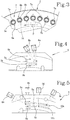
Figure 4 is a front view of a detail of a first embodiment of a measuring device of a unit for measuring the pressure drop in a smoking article according to this invention; -
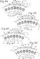
Figures 4A-4D schematically illustrate a sequence of operating steps of a unit for measuring the pressure drop in a smoking article according to the first embodiment of the measuring device ofFigure 4 ; -
Figure 5 is a front view of a detail of a second embodiment of a measuring device of a unit for measuring the pressure drop in a smoking article according to this invention; and -
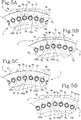
Figures 5A-5D schematically illustrate a sequence of operating steps of a unit for measuring the pressure drop in a smoking article according to the first embodiment of the measuring device ofFigure 5 . - With reference to the accompanying drawings, the
numeral 1 denotes in its entirety a unit for measuring the pressure drop in a smoking article, hereinafter referred to simply asunit 1. - The
unit 1 comprises aconveyor 2 comprising a plurality ofhousing seats 3, preferably suction seats, configured to receive and transversely feed a plurality of rod-shaped smoking articles 100 along a feed path P. - For convenience of illustration,
Figures 1 and 2 show only onearticle 100. Theunit 1 then comprises afixed measuring device 4 disposed on the feed path P and configured to measure a value of pressure drop in eacharticle 100. - The
articles 100 are thus movable relative to themeasuring device 4. With reference toFigures 4 and 5 , themeasuring device 4 comprises at least oneair loading slot compressed air source - The unit also comprises connecting means 7 disposed on the
conveyor 2 and configured to connect at least oneair loading slot housing seats 3 in order to feed an air flow to thearticles 100. Advantageously, according to this invention, themeasuring device 4 comprises at least twoair loading slots compressed air sources consecutive housing seats 3 to differentair loading slots - For example, with reference to
Figure 4A , afirst article 100a is adapted to be loaded with a first air flow from thecompressed air source 6a through theair loading slot 5a, while asecond article 100b is adapted to be loaded with a second air flow from thecompressed air source 6b through theair loading slot 5b. - In other words, connecting the
articles 100 selectively to alternately differentair loading slots air loading slots article 100 and the next without theloading slot article 100 at a time. - Thanks to the selective connection of the
articles alternate loading slots loading slots - Preferably, therefore, the
loading slots measuring device 4, whilst the connecting means 7 formed on the conveyor are movable along the feed path P together with thearticles 100. - It should be noted that in the embodiments illustrated, there are 2
loading slots loading slots - The
unit 1 is thus advantageously suitable for easy installation in any machine for making smokingarticles 100 in order to efficiently measure the pressure drop values in thearticles 100. - Moreover, with reference to the embodiments of this invention illustrated in the accompanying drawings, the
conveyor 2 is preferably a drum which rotates about an axis of rotation X and has, for eachhousing seat 3, at least one supporting element 3' for an end portion of anarticle 100 housed in thehousing seat 3. - The supporting elements 3' are advantageously configured to make a sealed compressed air connection with the compressed air sources 6 in order to obtain a correct measurement.
- More specifically, the supporting element 3' is associated with the connecting means 7 and the feed path P is a circular path.
- As shown in
Figure 2 , the supporting elements 3' engage the ends of thearticles 100 only at a measuring zone M located at the measuringdevice 4 to allow measuring operations to be carried out. In the embodiment illustrated, the measuring zone M is engaged by means of supporting elements 3' which are fixed to thedrum 2 at external inclined discs 2' that are configured to travel along a trajectory lying in a plane transverse to the axis of rotation X of thedrum 2. Alternatively, for example in an embodiment not illustrated in the accompanying drawings, the supporting elements 3' might be movable towards and away from thearticles 100 along the longitudinal axes thereof so as to selectively engage thearticles 100 at the measuring zone M. - Preferably, the two
loading slots articles 100 and run alongside each other in a direction perpendicular to the feed path P. More specifically, as shown in the accompanying drawings, therefore, the twoloading slots - With reference to
Figure 3 , the connecting means 7 preferably comprise, for eachhousing seat 3, a respective connectingslot article air loading slot slots consecutive housing seats slots air loading slots - For example, with reference to
Figure 4A , afirst article 100a, disposed in afirst housing seat 3a with which a first connectingslot 7a is associated, is adapted to be loaded with a first air flow from the compressedair source 6a through a firstair loading slot 5a, while asecond article 100b, disposed in asecond housing seat 3b (downstream of thefirst housing seat 3a) with which a second connectingslot 7b is associated, is adapted to be loaded with a second air flow from the compressedair source 6b through a secondair loading slot 5b. - Preferably, the connecting
slots respective article air loading slot - Preferably, the measuring
device 4 comprises, for eachair loading slot respective measuring slot air loading slot - Advantageously, inside each measuring
slot respective article slot air loading slot - Advantageously, therefore, the air is loaded into the
articles 100 through theloading slots slots - Preferably, the measuring
slots articles 100. - Preferably, the measuring
slots loading slots - As clearly shown in
Figures 4 and 5 , theair loading slots slots - With reference in particular to
Figures 4A-4D and5A-5D , it may also be noted that, preferably, for an operating stretch of the feed path P (whose length or angular size is preferably approximately half the length or angular size of therespective loading slot slot air loading slot respective article - Preferably, also, as illustrated in the accompanying drawings, the operating stretch just mentioned coincides with the length of the measuring
slot - As clearly shown in
Figures 4 and 5 , each measuringslot air loading slot air loading slot article 100 is in communication with that end portion of the of theair loading slot - Preferably, the end portion of the
air loading slot air loading slot - According to this invention, the
conveyor 2 preferably comprises, for eachhousing seat respective vent respective measuring slot slot vents conveyor 3 in at least two alternate sets in such a way thatconsecutive vents different measuring slots - The
vents slots conveyor 3 at eachhousing seat - In particular, for each
housing seat respective vent slot slot housing seat respective measuring slot respective vent other measuring slot - In other terms, for each
housing seat slot vent next housing seat - Preferably, each
vent slot slot - With reference to the embodiment illustrated in
Figures 5A-5D , the measuringdevice 4 advantageously comprises, for eachair loading slot air pre-loading slot air loading slot compressed air source air source air loading slot - More specifically, the connecting means 7 are configured to alternately connect at least one
air pre-loading slot housing seats 3 and, still more preferably, to connectconsecutive housing seats air pre-loading slots - Advantageously, therefore, before being connected to the
air loading slot article 100 is first connected to anair pre-loading slot air pre-loading chambers article 100 and to allow high RTD values to be measured efficiently. - Preferably, each
air pre-loading slot air loading slot article 100 is placed sequentially in fluid communication, by the connecting means 7, first with anair pre-loading slot air loading slot - That way, the overall length of the stretch along which each
article 100 is loaded with air is increased. - It should be noted that if the
conveyor 2 is a drum, theair pre-loading slots air pre-loading slot air loading slot - It should be noted that the lengths of the
air loading slots air pre-loading slots slots - Also part of this invention is a method for measuring the pressure drop in a
smoking article 100, comprising the following steps: - transversely feeding a plurality of
articles 100 along a feed path P through a fixedmeasuring device 4, where the measuringdevice 4 comprises twoair loading slots compressed air sources - placing one end of each
smoking article 100 in fluid communication with the at least oneair loading slot - measuring the value of pressure drop of each
article 100 connected to theair loading slot consecutive articles 100 to differentair loading slots - Preferably, the step of measuring the pressure drop of an
article 100a, performed while thearticle 100 is connected to the respectiveair loading slot 5a, is performed simultaneously with a step of placing one end of the nextconsecutive article 100b in fluid communication with a differentair loading slot 5b. - Advantageously, air can be loaded into each
article 100 for a longer length of time. - Preferably, also, the step of measuring a
first article 100a starts simultaneously with the starting of the step of placing one end of asecond article 100b, following thefirst article 100a, in fluid communication with a respectiveair loading slot 5b. - With reference to the accompanying drawings, the
air loading slots first article 100 starts while the end of thefirst article 100a is disposed at an end portion of the respectiveair loading slot 5a, further downstream, so that the step of measuring thefirst article 100a starts substantially simultaneously with the starting of the step of placing one end of asecond article 100b in fluid communication with the respectiveair loading slot 5b. - Preferably, also, the step of measuring is accomplished by connecting to each other the end of the
article 100 being measured, theair loading slot slot slot article 100. - In particular, the step of connecting each measuring
slot air loading slot respective article 100 occurs after the step of connecting theair loading slot article 100. - Preferably, each step of measuring performed in one
measuring slot other measuring slot - The operation of the measuring method is described briefly below with reference to the example embodiment of
Figures 4A-4D and with particular regard to the advancing motion of twoconsecutive articles - In
Figure 4A : - the
first article 100a is starting to be loaded with air from the compressedair source 6a through the connectingslot 7a and theloading slot 5a; therespective vent 9a, on the other hand, is not in operation; - the
second article 100b is being loaded with air from the compressedair source 6b through the connectingslot 7b and theloading slot 5b and, simultaneously, the step of measuring thesecond article 100b through the measuringslot 8b is starting; thevent 9b starts moving across the measuringslot 8a to relieve the accumulated pressure. - In
Figure 4B : - the
first article 100a is continuing to be loaded with air; therespective vent 9a is not in operation; - the
second article 100b is ending the step of loading with air and, simultaneously, the step of measuring is ending; thevent 9b is ending the step of relieving. - In
Figure 4C : - the
first article 100a is continuing to be loaded with air and, simultaneously, the step of measuring through the measuringslot 8a is starting and the step of thevent 9a relieving pressure through the measuringslot 8b is starting; - the
second article 100b has been measured and is no longer in fluid communication with the measuringdevice 4; - a further
second article 100b, upstream of thefirst article 100a, is starting to be loaded with air from the compressedair source 6b through the connectingslot 7b and theloading slot 5b; therespective vent 9b, on the other hand, is not in operation; - In
Figure 4D : - the
first article 100a is ending the step of loading with air and, simultaneously, the step of measuring; thevent 9a is also ending the step of relieving; - the further
second article 100b, on the other hand, is continuing to be loaded with air. - The cycle described with reference to
Figures 4A to 4D is repeated cyclically along the entire feed path P to allow all thearticles 100 to be measured. Compared to what is described above with reference toFigures 4A-4D , the embodiment illustrated inFigures 5A-5D comprises an additional step of preloading with air according to this invention. - In other words, before reaching the
loading slots articles 100 undergo a step of preloading in therespective preloading slots - This invention overcomes the disadvantages of the prior art by providing a unit and a method for measuring the pressure drop in a smoking article making it possible to increase the time available for supplying an air flow into the article so as to be able to measure real pressure drop values of a wide range of articles, in particular those whose RTD is higher than that of traditional cigarettes. Thanks to the air loading slots which are longer than those of the prior art and which are managed with alternate selective logic, it is possible, under otherwise equal conditions, to load the smoking articles with a larger quantity of air.
- The invention is therefore able to enhance the versatility of machines for making smoking articles without modifying the overall dimensions of the measuring unit and without having to modify the speed at which the articles are fed.
Claims (22)
- A unit (1) for measuring the pressure drop in a smoking article (100), comprising:- a conveyor (2) comprising a plurality of housing seats (3) configured to receive and transversely feed a plurality of rod-shaped smoking articles (100) along a feed path (P);- a fixed measuring device (4) disposed on the feed path (P) and configured to measure a value of pressure drop in each article (100), wherein the measuring device (4) comprises at least one air loading slot (5a, 5b) connected or connectable to a compressed air source (6a, 6b);- connecting means (7) disposed on the conveyor (2) and configured to connect the at least one air loading slot (5a, 5b) sequentially to one of the housing seats (3) in order to feed an air flow to the articles (100); characterized in that the measuring device (4) comprises at least two air loading slots (5a, 5b) connected or connectable to respective, distinct compressed air sources (6a, 6b) and in that the connecting means (7) are configured to alternately connect consecutive housing seats (3a, 3b) to different air loading slots (5a, 5b).
- The unit (1) according to claim 1, wherein the at least two air loading slots (5a, 5b) extend along respective directions of extension parallel to the feed path (P) of the articles (100) and are juxtaposed with each other along a direction perpendicular to the feed path (P), and wherein the connecting means (7) comprise, for each housing seat (3a, 3b), a respective connecting slot (7a, 7b) configured to pneumatically connect the respective article (100a, 100b) to a respective air loading slot (5a, 5b) and wherein the connecting slots (7a, 7b) are disposed in at least two alternate sets in such a way that consecutive housing seats (3a, 3b) correspond to connecting slots (7a, 7b) of distinct sets configured to be connected to different air loading slots (5a, 5b).
- The unit (1) according to claim 2, wherein the connecting slots (7a, 7b) extend between the respective article (100a, 100b) and the respective air loading slot (5a, 5b) along respective directions of extension transverse, preferably perpendicular, to the feed path (P).
- The unit (1) according to one or more of the preceding claims, wherein the measuring device (5) comprises, for each air loading slot (5a, 5b), a respective measuring slot (8a, 8b) which is juxtaposed with the respective air loading slot (5a, 5b) and inside which there is a pressure sensor configured to measure a value of pressure drop associated with a respective article (100a, 100b), each measuring slot (8a, 8b) being placed in fluid communication with the respective air loading slot (5a, 5b) by the connecting means (7).
- The unit (1) according to claim 4, wherein the measuring slot (8a, 8b), the respective air loading slot (5a, 5b) and the respective article (100a, 100b) to be measured are placed in mutual fluid communication simultaneously by the connecting means (7) for a certain operating stretch of the feed path (P).
- The unit (1) according to claim 5, wherein each measuring slot (8a, 8b) at least partly overlaps the respective air loading slot (5a, 5b) along the feed path (P), and wherein the measuring slot (8a, 8b) preferably overlaps only an end portion of the respective air loading slot (5a, 5b) along the feed path (P) so that the pressure is measured only when the article (100a, 100b) is in communication with that end portion of the of the air loading slot (5a, 5b).
- The unit (1) according to any one of claims 4 to 6, wherein the measuring slots (8a, 8b) extend along respective directions of extension parallel to the feed path (P) of the articles (100a, 100b).
- The unit (1) according to claim 7, when dependent on claim 3, wherein the air loading slots (5a, 5b) are interposed between the measuring slots (8a, 8b) relative to a direction transverse to the feed path (P).
- The unit (1) according to one or more of claims 4-6, wherein the conveyor (2) comprises, for each housing seat (3a, 3b), a respective vent (9a, 9b) configured to intercept a respective measuring slot (8a, 8b) and to relieve the pressure in the measuring slot (8a, 8b), and wherein the vents (9a, 9b) are disposed on the conveyor (3) in at least two alternate sets in such a way that consecutive vents (9a, 9b) intercept different measuring slots (8a, 8b).
- The unit (1) according to claim 9, wherein, for each housing seat (3a, 3b), the respective vent (9a, 9b) is disposed on the side opposite to the respective connecting slot (7a, 7b) so that when the connecting slot (7a, 7b) associated with the housing seat (3a, 3b) is in communication with a respective measuring slot (8a, 8b), the respective vent (9a, 9b) is in communication with the other measuring slot (8a, 8b).
- The unit (1) according to one or more of the preceding claims, wherein the conveyor (2) is a drum which rotates about an axis of rotation (X) and has, for each housing seat (3a, 3b), at least one supporting element (3') for an end portion of an article (100a, 100b) housed in the housing seat (3a, 3b), the supporting element (3') being associated with the connecting means (7); and wherein the feed path (P) defines a circular path, the at least two air loading slots (5a, 5b) extending along arcuate directions of extension.
- The unit (1) according to one or more of the preceding claims, wherein the measuring device (4) comprises, for each air loading slot (5a, 5b), a respective air pre-loading slot (10a, 10b) disposed upstream of the air loading slot (5a, 5b) relative to the feed path (P) and connected or connectable to a respective compressed air source (6c, 6d) distinct from the compressed air source (6a, 6b) of the respective air loading slot (5a, 5b) and wherein the connecting means (7) are also configured to alternately connect consecutive housing seats (3a, 3b) to different air pre-loading slots (10a, 10b).
- The unit (1) according to claim 11, wherein each air pre-loading slot (10a, 10b) is aligned with the respective air loading slot (5a, 5b) in such a way that each article (100a, 100b) is placed in fluid communication, by the connecting means (7), first with an air pre-loading slot (10a, 10b) and then with the respective air loading slot (5a, 5b).
- The unit (1) according to claim 12 or 13, wherein each air pre-loading slot (10a, 10b) is greater than or equal to the respective air loading slot (5a, 5b) in length.
- A method for measuring the pressure drop in a smoking article (100), comprising the following steps:- transversely feeding a plurality of rod-shaped smoking articles (100) along a feed path (P) through a fixed measuring device (4), the measuring device (4) comprising at least one air loading slot (5a, 5b) connected or connectable to a compressed air source (6a, 6b);- placing one end of each smoking article (100) in fluid communication with the at least one air loading slot (5a, 5b);- measuring the value of pressure drop of each article connected to the air loading slot (5a, 5b);characterized in that the measuring device (4) comprises two air loading slots (5a, 5b) connected or connectable to distinct compressed air sources (6a, 6b) and in that the step of measuring the value of pressure drop of each article (100) is performed by alternately connecting the ends of consecutive articles (100a, 100b) to different air loading slots (5a, 5b).
- The method according to claim 15, wherein the step of measuring the value of pressure drop of an article (100a, 100b), performed while the article (100a, 100b) is connected to an air loading slot (5a, 5b), is performed simultaneously with a step of placing one end of the next consecutive article (100a, 100b) in fluid communication with a different air loading slot (5a, 5b).
- The method according to claim 15 or 16, wherein the step of measuring a first article (100a) starts simultaneously with the starting of the step of placing one end of a second article (100b), following the first article (100a), in fluid communication with a respective air loading slot (5a, 5b).
- The method according to claim 17, wherein the air loading slots (5a, 5b) have the same extension, be it linear or angular, along the feed path (P) and wherein the step of measuring the pressure drop of the first article (100) starts while the end of the first article (100a) is disposed at an end portion of the respective air loading slot (5a), further downstream, so that the step of measuring the first article (100a) starts substantially simultaneously with the starting of the step of placing one end of a second article (100b) in fluid communication with the respective air loading slot (5b).
- The method according to one or more of claims 15 to 18, wherein the measuring device (4) comprises, for each air loading slot (5a, 5b), a respective measuring slot (8a, 8b) inside which there is a pressure sensor, and wherein the step of measuring is performed by connecting together the end of the article (100a, 100b) measured, the air loading slot (5a, 5b) and the measuring slot (8a, 8b) by means of a single connecting slot (7a, 7b) which is movable as one with the article (100a, 100b), there being two distinct sets of connecting slots (7a, 7b) disposed in alternate succession at consecutive articles (100, 100b) so that consecutive articles (100a, 100b) are connected to different air loading slots (5a, 5b) and different measuring slots (8a, 8b).
- The method according to claim 19, wherein the step of connecting each measuring slot (8a, 8b) to the respective air loading slot (5a, 5b) and the end of the respective article (100a, 100b) occurs after the step of connecting air loading slot (5a, 5b) to the end of the article (100a, 100b).
- The method according to claim 19 or 20, wherein each step of measuring performed in one measuring slot (8a, 8b) is accompanied by a corresponding step, preferably simultaneous, of venting the pressure in the other measuring slot (8a, 8b).
- A unit (1) for measuring the pressure drop in a smoking article (100), comprising:- a conveyor (2) comprising a plurality of housing seats (3) configured to receive and transversely feed a plurality of rod-shaped smoking articles (100) along a feed path (P);- a fixed measuring device (4) disposed on the feed path (P) and configured to measure a value of pressure drop in each article (100), wherein the measuring device (4) comprises at least one air loading slot (5a, 5b) connected or connectable to a compressed air source (6a, 6b);- connecting means (7) disposed on the conveyor (2) and configured to connect the at least one air loading slot (5a, 5b) sequentially to one of the housing seats (3) in order to feed an air flow to the articles (100); characterized in that the measuring device (4) comprises, for each at least one air loading slot (5a, 5b), a respective air pre-loading slot (10a, 10b) disposed upstream of the air loading slot (5a, 5b) relative to the feed path (P) and connected or connectable to a respective compressed air source (6c, 6d) distinct from the compressed air source (6a, 6b) of the respective air loading slot (5a, 5b) and wherein the connecting means (7) are also configured to connect the at least one pre-loading slot (10a, 10b) to one of the housing seats (3).
Priority Applications (1)
| Application Number | Priority Date | Filing Date | Title |
|---|---|---|---|
| PL19183769T PL3607838T3 (en) | 2018-08-10 | 2019-07-02 | Unit and method for measuring the pressure drop in a smoking article |
Applications Claiming Priority (1)
| Application Number | Priority Date | Filing Date | Title |
|---|---|---|---|
| IT102018000008029A IT201800008029A1 (en) | 2018-08-10 | 2018-08-10 | Unit and method for measuring the pressure drop across a smoking article |
Publications (2)
| Publication Number | Publication Date |
|---|---|
| EP3607838A1 true EP3607838A1 (en) | 2020-02-12 |
| EP3607838B1 EP3607838B1 (en) | 2021-04-21 |
Family
ID=63965976
Family Applications (1)
| Application Number | Title | Priority Date | Filing Date |
|---|---|---|---|
| EP19183769.9A Active EP3607838B1 (en) | 2018-08-10 | 2019-07-02 | Unit and method for measuring the pressure drop in a smoking article |
Country Status (3)
| Country | Link |
|---|---|
| EP (1) | EP3607838B1 (en) |
| IT (1) | IT201800008029A1 (en) |
| PL (1) | PL3607838T3 (en) |
Citations (3)
| Publication number | Priority date | Publication date | Assignee | Title |
|---|---|---|---|---|
| US3418844A (en) | 1966-12-02 | 1968-12-31 | Hauni Werke Koerber & Co Kg | Method and apparatus for testing cigarettes or the like |
| DE3341686A1 (en) | 1983-01-12 | 1984-06-14 | Hauni-Werke Körber & Co KG, 2050 Hamburg | Apparatus for testing cigarettes |
| GB2159284A (en) * | 1984-05-24 | 1985-11-27 | Hauni Werke Koerber & Co Kg | Method and apparatus for testing rod-shaped articles of the tobacco processing industry |
-
2018
- 2018-08-10 IT IT102018000008029A patent/IT201800008029A1/en unknown
-
2019
- 2019-07-02 PL PL19183769T patent/PL3607838T3/en unknown
- 2019-07-02 EP EP19183769.9A patent/EP3607838B1/en active Active
Patent Citations (3)
| Publication number | Priority date | Publication date | Assignee | Title |
|---|---|---|---|---|
| US3418844A (en) | 1966-12-02 | 1968-12-31 | Hauni Werke Koerber & Co Kg | Method and apparatus for testing cigarettes or the like |
| DE3341686A1 (en) | 1983-01-12 | 1984-06-14 | Hauni-Werke Körber & Co KG, 2050 Hamburg | Apparatus for testing cigarettes |
| GB2159284A (en) * | 1984-05-24 | 1985-11-27 | Hauni Werke Koerber & Co Kg | Method and apparatus for testing rod-shaped articles of the tobacco processing industry |
Also Published As
| Publication number | Publication date |
|---|---|
| IT201800008029A1 (en) | 2020-02-10 |
| PL3607838T3 (en) | 2021-11-08 |
| EP3607838B1 (en) | 2021-04-21 |
Similar Documents
| Publication | Publication Date | Title |
|---|---|---|
| EP2129581B1 (en) | A machine and a method for manufacturing pouches of cohesionless material | |
| EP2249670B1 (en) | System for analyzing a filter element associated with a smoking article, and associated method | |
| KR20070091272A (en) | Apparatus and method for forming a tobacco filter by moving parallel to fill particles in the cavity | |
| CN103491812B (en) | Conveying of rod-shaped products in the tobacco processing industry | |
| US20120080043A1 (en) | Introducing Objects Into Elongate Smoking Articles | |
| US4969551A (en) | Method of and apparatus for rolling rod-shaped articles | |
| CN110234240B (en) | Method and system for producing multi-segment articles of the tobacco industry | |
| EP3119215A1 (en) | A smoking article assembly machine | |
| CN108430240B (en) | Filter Manufacturing Equipment | |
| EP3607838B1 (en) | Unit and method for measuring the pressure drop in a smoking article | |
| US7578777B2 (en) | Equipment for manufacturing composite filters | |
| US3962906A (en) | Method and apparatus for testing cigarettes or the like | |
| US4185941A (en) | Method and apparatus for assembling rod-like articles | |
| US4010678A (en) | Method and apparatus for making composite filter plugs | |
| US6079545A (en) | Apparatus for varying the distances between the ends of rod-shaped articles of the tobacco processing industry | |
| JP2020508677A (en) | Method of reducing garniture belt stress in tobacco industry machine, method of reducing rejection in tobacco industry machine, and garniture device for tobacco industry machine | |
| US4714083A (en) | Making of multi-element smoking article rod | |
| TW202115399A (en) | Inspection apparatus for rod-shaped tobacco products | |
| FI68162C (en) | ANORDING FOR FORMING AV CHANNEL AND PERIPHERAL FILTER ELEMENT | |
| CN116761520A (en) | Roller device for transverse conveying of rod-shaped articles for the tobacco processing industry | |
| WO2017001348A1 (en) | Filter rod maker with air dust removal | |
| KR20230039681A (en) | Device for manufacturing multi-segment rod-shaped articles | |
| RU2808967C2 (en) | Feeder device for feeding tobacco product segment | |
| CN119453556A (en) | Production of rod-shaped products in the tobacco processing industry | |
| US4036118A (en) | Rod-like articles |
Legal Events
| Date | Code | Title | Description |
|---|---|---|---|
| PUAI | Public reference made under article 153(3) epc to a published international application that has entered the european phase |
Free format text: ORIGINAL CODE: 0009012 |
|
| STAA | Information on the status of an ep patent application or granted ep patent |
Free format text: STATUS: THE APPLICATION HAS BEEN PUBLISHED |
|
| AK | Designated contracting states |
Kind code of ref document: A1 Designated state(s): AL AT BE BG CH CY CZ DE DK EE ES FI FR GB GR HR HU IE IS IT LI LT LU LV MC MK MT NL NO PL PT RO RS SE SI SK SM TR |
|
| AX | Request for extension of the european patent |
Extension state: BA ME |
|
| STAA | Information on the status of an ep patent application or granted ep patent |
Free format text: STATUS: REQUEST FOR EXAMINATION WAS MADE |
|
| 17P | Request for examination filed |
Effective date: 20200715 |
|
| RBV | Designated contracting states (corrected) |
Designated state(s): AL AT BE BG CH CY CZ DE DK EE ES FI FR GB GR HR HU IE IS IT LI LT LU LV MC MK MT NL NO PL PT RO RS SE SI SK SM TR |
|
| GRAP | Despatch of communication of intention to grant a patent |
Free format text: ORIGINAL CODE: EPIDOSNIGR1 |
|
| STAA | Information on the status of an ep patent application or granted ep patent |
Free format text: STATUS: GRANT OF PATENT IS INTENDED |
|
| INTG | Intention to grant announced |
Effective date: 20201130 |
|
| GRAS | Grant fee paid |
Free format text: ORIGINAL CODE: EPIDOSNIGR3 |
|
| GRAA | (expected) grant |
Free format text: ORIGINAL CODE: 0009210 |
|
| STAA | Information on the status of an ep patent application or granted ep patent |
Free format text: STATUS: THE PATENT HAS BEEN GRANTED |
|
| AK | Designated contracting states |
Kind code of ref document: B1 Designated state(s): AL AT BE BG CH CY CZ DE DK EE ES FI FR GB GR HR HU IE IS IT LI LT LU LV MC MK MT NL NO PL PT RO RS SE SI SK SM TR |
|
| REG | Reference to a national code |
Ref country code: GB Ref legal event code: FG4D |
|
| REG | Reference to a national code |
Ref country code: CH Ref legal event code: EP |
|
| REG | Reference to a national code |
Ref country code: DE Ref legal event code: R096 Ref document number: 602019004017 Country of ref document: DE Ref country code: IE Ref legal event code: FG4D |
|
| REG | Reference to a national code |
Ref country code: AT Ref legal event code: REF Ref document number: 1383699 Country of ref document: AT Kind code of ref document: T Effective date: 20210515 |
|
| REG | Reference to a national code |
Ref country code: LT Ref legal event code: MG9D |
|
| REG | Reference to a national code |
Ref country code: AT Ref legal event code: MK05 Ref document number: 1383699 Country of ref document: AT Kind code of ref document: T Effective date: 20210421 |
|
| REG | Reference to a national code |
Ref country code: NL Ref legal event code: MP Effective date: 20210421 |
|
| PG25 | Lapsed in a contracting state [announced via postgrant information from national office to epo] |
Ref country code: LT Free format text: LAPSE BECAUSE OF FAILURE TO SUBMIT A TRANSLATION OF THE DESCRIPTION OR TO PAY THE FEE WITHIN THE PRESCRIBED TIME-LIMIT Effective date: 20210421 Ref country code: HR Free format text: LAPSE BECAUSE OF FAILURE TO SUBMIT A TRANSLATION OF THE DESCRIPTION OR TO PAY THE FEE WITHIN THE PRESCRIBED TIME-LIMIT Effective date: 20210421 Ref country code: FI Free format text: LAPSE BECAUSE OF FAILURE TO SUBMIT A TRANSLATION OF THE DESCRIPTION OR TO PAY THE FEE WITHIN THE PRESCRIBED TIME-LIMIT Effective date: 20210421 Ref country code: NL Free format text: LAPSE BECAUSE OF FAILURE TO SUBMIT A TRANSLATION OF THE DESCRIPTION OR TO PAY THE FEE WITHIN THE PRESCRIBED TIME-LIMIT Effective date: 20210421 Ref country code: AT Free format text: LAPSE BECAUSE OF FAILURE TO SUBMIT A TRANSLATION OF THE DESCRIPTION OR TO PAY THE FEE WITHIN THE PRESCRIBED TIME-LIMIT Effective date: 20210421 Ref country code: BG Free format text: LAPSE BECAUSE OF FAILURE TO SUBMIT A TRANSLATION OF THE DESCRIPTION OR TO PAY THE FEE WITHIN THE PRESCRIBED TIME-LIMIT Effective date: 20210721 |
|
| PG25 | Lapsed in a contracting state [announced via postgrant information from national office to epo] |
Ref country code: NO Free format text: LAPSE BECAUSE OF FAILURE TO SUBMIT A TRANSLATION OF THE DESCRIPTION OR TO PAY THE FEE WITHIN THE PRESCRIBED TIME-LIMIT Effective date: 20210721 Ref country code: LV Free format text: LAPSE BECAUSE OF FAILURE TO SUBMIT A TRANSLATION OF THE DESCRIPTION OR TO PAY THE FEE WITHIN THE PRESCRIBED TIME-LIMIT Effective date: 20210421 Ref country code: RS Free format text: LAPSE BECAUSE OF FAILURE TO SUBMIT A TRANSLATION OF THE DESCRIPTION OR TO PAY THE FEE WITHIN THE PRESCRIBED TIME-LIMIT Effective date: 20210421 Ref country code: PT Free format text: LAPSE BECAUSE OF FAILURE TO SUBMIT A TRANSLATION OF THE DESCRIPTION OR TO PAY THE FEE WITHIN THE PRESCRIBED TIME-LIMIT Effective date: 20210823 Ref country code: SE Free format text: LAPSE BECAUSE OF FAILURE TO SUBMIT A TRANSLATION OF THE DESCRIPTION OR TO PAY THE FEE WITHIN THE PRESCRIBED TIME-LIMIT Effective date: 20210421 Ref country code: IS Free format text: LAPSE BECAUSE OF FAILURE TO SUBMIT A TRANSLATION OF THE DESCRIPTION OR TO PAY THE FEE WITHIN THE PRESCRIBED TIME-LIMIT Effective date: 20210821 Ref country code: GR Free format text: LAPSE BECAUSE OF FAILURE TO SUBMIT A TRANSLATION OF THE DESCRIPTION OR TO PAY THE FEE WITHIN THE PRESCRIBED TIME-LIMIT Effective date: 20210722 |
|
| REG | Reference to a national code |
Ref country code: DE Ref legal event code: R097 Ref document number: 602019004017 Country of ref document: DE |
|
| PG25 | Lapsed in a contracting state [announced via postgrant information from national office to epo] |
Ref country code: RO Free format text: LAPSE BECAUSE OF FAILURE TO SUBMIT A TRANSLATION OF THE DESCRIPTION OR TO PAY THE FEE WITHIN THE PRESCRIBED TIME-LIMIT Effective date: 20210421 Ref country code: SM Free format text: LAPSE BECAUSE OF FAILURE TO SUBMIT A TRANSLATION OF THE DESCRIPTION OR TO PAY THE FEE WITHIN THE PRESCRIBED TIME-LIMIT Effective date: 20210421 Ref country code: DK Free format text: LAPSE BECAUSE OF FAILURE TO SUBMIT A TRANSLATION OF THE DESCRIPTION OR TO PAY THE FEE WITHIN THE PRESCRIBED TIME-LIMIT Effective date: 20210421 Ref country code: CZ Free format text: LAPSE BECAUSE OF FAILURE TO SUBMIT A TRANSLATION OF THE DESCRIPTION OR TO PAY THE FEE WITHIN THE PRESCRIBED TIME-LIMIT Effective date: 20210421 Ref country code: SK Free format text: LAPSE BECAUSE OF FAILURE TO SUBMIT A TRANSLATION OF THE DESCRIPTION OR TO PAY THE FEE WITHIN THE PRESCRIBED TIME-LIMIT Effective date: 20210421 Ref country code: EE Free format text: LAPSE BECAUSE OF FAILURE TO SUBMIT A TRANSLATION OF THE DESCRIPTION OR TO PAY THE FEE WITHIN THE PRESCRIBED TIME-LIMIT Effective date: 20210421 Ref country code: ES Free format text: LAPSE BECAUSE OF FAILURE TO SUBMIT A TRANSLATION OF THE DESCRIPTION OR TO PAY THE FEE WITHIN THE PRESCRIBED TIME-LIMIT Effective date: 20210421 |
|
| PLBE | No opposition filed within time limit |
Free format text: ORIGINAL CODE: 0009261 |
|
| STAA | Information on the status of an ep patent application or granted ep patent |
Free format text: STATUS: NO OPPOSITION FILED WITHIN TIME LIMIT |
|
| 26N | No opposition filed |
Effective date: 20220124 |
|
| PG25 | Lapsed in a contracting state [announced via postgrant information from national office to epo] |
Ref country code: MC Free format text: LAPSE BECAUSE OF FAILURE TO SUBMIT A TRANSLATION OF THE DESCRIPTION OR TO PAY THE FEE WITHIN THE PRESCRIBED TIME-LIMIT Effective date: 20210421 |
|
| REG | Reference to a national code |
Ref country code: BE Ref legal event code: MM Effective date: 20210731 |
|
| PG25 | Lapsed in a contracting state [announced via postgrant information from national office to epo] |
Ref country code: IS Free format text: LAPSE BECAUSE OF FAILURE TO SUBMIT A TRANSLATION OF THE DESCRIPTION OR TO PAY THE FEE WITHIN THE PRESCRIBED TIME-LIMIT Effective date: 20210821 Ref country code: LU Free format text: LAPSE BECAUSE OF NON-PAYMENT OF DUE FEES Effective date: 20210702 Ref country code: AL Free format text: LAPSE BECAUSE OF FAILURE TO SUBMIT A TRANSLATION OF THE DESCRIPTION OR TO PAY THE FEE WITHIN THE PRESCRIBED TIME-LIMIT Effective date: 20210421 |
|
| PG25 | Lapsed in a contracting state [announced via postgrant information from national office to epo] |
Ref country code: IT Free format text: LAPSE BECAUSE OF FAILURE TO SUBMIT A TRANSLATION OF THE DESCRIPTION OR TO PAY THE FEE WITHIN THE PRESCRIBED TIME-LIMIT Effective date: 20210421 Ref country code: IE Free format text: LAPSE BECAUSE OF NON-PAYMENT OF DUE FEES Effective date: 20210702 Ref country code: BE Free format text: LAPSE BECAUSE OF NON-PAYMENT OF DUE FEES Effective date: 20210731 |
|
| REG | Reference to a national code |
Ref country code: CH Ref legal event code: PL |
|
| PG25 | Lapsed in a contracting state [announced via postgrant information from national office to epo] |
Ref country code: LI Free format text: LAPSE BECAUSE OF NON-PAYMENT OF DUE FEES Effective date: 20220731 Ref country code: CH Free format text: LAPSE BECAUSE OF NON-PAYMENT OF DUE FEES Effective date: 20220731 |
|
| PG25 | Lapsed in a contracting state [announced via postgrant information from national office to epo] |
Ref country code: CY Free format text: LAPSE BECAUSE OF FAILURE TO SUBMIT A TRANSLATION OF THE DESCRIPTION OR TO PAY THE FEE WITHIN THE PRESCRIBED TIME-LIMIT Effective date: 20210421 |
|
| P01 | Opt-out of the competence of the unified patent court (upc) registered |
Effective date: 20230527 |
|
| PG25 | Lapsed in a contracting state [announced via postgrant information from national office to epo] |
Ref country code: HU Free format text: LAPSE BECAUSE OF FAILURE TO SUBMIT A TRANSLATION OF THE DESCRIPTION OR TO PAY THE FEE WITHIN THE PRESCRIBED TIME-LIMIT; INVALID AB INITIO Effective date: 20190702 |
|
| GBPC | Gb: european patent ceased through non-payment of renewal fee |
Effective date: 20230702 |
|
| PG25 | Lapsed in a contracting state [announced via postgrant information from national office to epo] |
Ref country code: MK Free format text: LAPSE BECAUSE OF FAILURE TO SUBMIT A TRANSLATION OF THE DESCRIPTION OR TO PAY THE FEE WITHIN THE PRESCRIBED TIME-LIMIT Effective date: 20210421 Ref country code: GB Free format text: LAPSE BECAUSE OF NON-PAYMENT OF DUE FEES Effective date: 20230702 |
|
| PG25 | Lapsed in a contracting state [announced via postgrant information from national office to epo] |
Ref country code: TR Free format text: LAPSE BECAUSE OF FAILURE TO SUBMIT A TRANSLATION OF THE DESCRIPTION OR TO PAY THE FEE WITHIN THE PRESCRIBED TIME-LIMIT Effective date: 20210421 |
|
| PG25 | Lapsed in a contracting state [announced via postgrant information from national office to epo] |
Ref country code: MT Free format text: LAPSE BECAUSE OF FAILURE TO SUBMIT A TRANSLATION OF THE DESCRIPTION OR TO PAY THE FEE WITHIN THE PRESCRIBED TIME-LIMIT Effective date: 20210421 |
|
| PGFP | Annual fee paid to national office [announced via postgrant information from national office to epo] |
Ref country code: DE Payment date: 20250729 Year of fee payment: 7 |
|
| PGFP | Annual fee paid to national office [announced via postgrant information from national office to epo] |
Ref country code: FR Payment date: 20250725 Year of fee payment: 7 |
|
| PGFP | Annual fee paid to national office [announced via postgrant information from national office to epo] |
Ref country code: PL Payment date: 20260618 Year of fee payment: 8 |