EP3607533B1 - Systems for operating a vehicle and associated methods - Google Patents
Systems for operating a vehicle and associated methods Download PDFInfo
- Publication number
- EP3607533B1 EP3607533B1 EP18720699.0A EP18720699A EP3607533B1 EP 3607533 B1 EP3607533 B1 EP 3607533B1 EP 18720699 A EP18720699 A EP 18720699A EP 3607533 B1 EP3607533 B1 EP 3607533B1
- Authority
- EP
- European Patent Office
- Prior art keywords
- passcode
- input device
- vehicle
- input
- component
- Prior art date
- Legal status (The legal status is an assumption and is not a legal conclusion. Google has not performed a legal analysis and makes no representation as to the accuracy of the status listed.)
- Active
Links
Images






Classifications
-
- B—PERFORMING OPERATIONS; TRANSPORTING
- B60—VEHICLES IN GENERAL
- B60R—VEHICLES, VEHICLE FITTINGS, OR VEHICLE PARTS, NOT OTHERWISE PROVIDED FOR
- B60R25/00—Fittings or systems for preventing or indicating unauthorised use or theft of vehicles
- B60R25/002—Locking of control actuating or transmitting means
- B60R25/003—Locking of control actuating or transmitting means locking of control actuating means
- B60R25/007—Locking of control actuating or transmitting means locking of control actuating means of hand actuated control means
- B60R25/008—Locking of control actuating or transmitting means locking of control actuating means of hand actuated control means comprising means for locking two or more control means together, e.g. hand-brake handle and gear shift lever
-
- B—PERFORMING OPERATIONS; TRANSPORTING
- B60—VEHICLES IN GENERAL
- B60K—ARRANGEMENT OR MOUNTING OF PROPULSION UNITS OR OF TRANSMISSIONS IN VEHICLES; ARRANGEMENT OR MOUNTING OF PLURAL DIVERSE PRIME-MOVERS IN VEHICLES; AUXILIARY DRIVES FOR VEHICLES; INSTRUMENTATION OR DASHBOARDS FOR VEHICLES; ARRANGEMENTS IN CONNECTION WITH COOLING, AIR INTAKE, GAS EXHAUST OR FUEL SUPPLY OF PROPULSION UNITS IN VEHICLES
- B60K35/00—Instruments specially adapted for vehicles; Arrangement of instruments in or on vehicles
-
- B—PERFORMING OPERATIONS; TRANSPORTING
- B60—VEHICLES IN GENERAL
- B60K—ARRANGEMENT OR MOUNTING OF PROPULSION UNITS OR OF TRANSMISSIONS IN VEHICLES; ARRANGEMENT OR MOUNTING OF PLURAL DIVERSE PRIME-MOVERS IN VEHICLES; AUXILIARY DRIVES FOR VEHICLES; INSTRUMENTATION OR DASHBOARDS FOR VEHICLES; ARRANGEMENTS IN CONNECTION WITH COOLING, AIR INTAKE, GAS EXHAUST OR FUEL SUPPLY OF PROPULSION UNITS IN VEHICLES
- B60K35/00—Instruments specially adapted for vehicles; Arrangement of instruments in or on vehicles
- B60K35/20—Output arrangements, i.e. from vehicle to user, associated with vehicle functions or specially adapted therefor
- B60K35/21—Output arrangements, i.e. from vehicle to user, associated with vehicle functions or specially adapted therefor using visual output, e.g. blinking lights or matrix displays
- B60K35/22—Display screens
-
- B—PERFORMING OPERATIONS; TRANSPORTING
- B60—VEHICLES IN GENERAL
- B60R—VEHICLES, VEHICLE FITTINGS, OR VEHICLE PARTS, NOT OTHERWISE PROVIDED FOR
- B60R25/00—Fittings or systems for preventing or indicating unauthorised use or theft of vehicles
- B60R25/01—Fittings or systems for preventing or indicating unauthorised use or theft of vehicles operating on vehicle systems or fittings, e.g. on doors, seats or windscreens
- B60R25/02—Fittings or systems for preventing or indicating unauthorised use or theft of vehicles operating on vehicle systems or fittings, e.g. on doors, seats or windscreens operating on the steering mechanism
- B60R25/021—Fittings or systems for preventing or indicating unauthorised use or theft of vehicles operating on vehicle systems or fittings, e.g. on doors, seats or windscreens operating on the steering mechanism restraining movement of the steering column or steering wheel hub, e.g. restraining means controlled by ignition switch
-
- B—PERFORMING OPERATIONS; TRANSPORTING
- B60—VEHICLES IN GENERAL
- B60R—VEHICLES, VEHICLE FITTINGS, OR VEHICLE PARTS, NOT OTHERWISE PROVIDED FOR
- B60R25/00—Fittings or systems for preventing or indicating unauthorised use or theft of vehicles
- B60R25/01—Fittings or systems for preventing or indicating unauthorised use or theft of vehicles operating on vehicle systems or fittings, e.g. on doors, seats or windscreens
- B60R25/08—Fittings or systems for preventing or indicating unauthorised use or theft of vehicles operating on vehicle systems or fittings, e.g. on doors, seats or windscreens operating on brakes or brake systems
- B60R25/083—Locking of foot-actuated control actuating means
-
- B—PERFORMING OPERATIONS; TRANSPORTING
- B60—VEHICLES IN GENERAL
- B60R—VEHICLES, VEHICLE FITTINGS, OR VEHICLE PARTS, NOT OTHERWISE PROVIDED FOR
- B60R25/00—Fittings or systems for preventing or indicating unauthorised use or theft of vehicles
- B60R25/20—Means to switch the anti-theft system on or off
- B60R25/2081—Means to switch the anti-theft system on or off combined with personal settings of other vehicle devices, e.g. mirrors, seats, steering wheels
-
- B—PERFORMING OPERATIONS; TRANSPORTING
- B60—VEHICLES IN GENERAL
- B60R—VEHICLES, VEHICLE FITTINGS, OR VEHICLE PARTS, NOT OTHERWISE PROVIDED FOR
- B60R25/00—Fittings or systems for preventing or indicating unauthorised use or theft of vehicles
- B60R25/20—Means to switch the anti-theft system on or off
- B60R25/209—Remote starting of engine
-
- B—PERFORMING OPERATIONS; TRANSPORTING
- B60—VEHICLES IN GENERAL
- B60R—VEHICLES, VEHICLE FITTINGS, OR VEHICLE PARTS, NOT OTHERWISE PROVIDED FOR
- B60R25/00—Fittings or systems for preventing or indicating unauthorised use or theft of vehicles
- B60R25/20—Means to switch the anti-theft system on or off
- B60R25/24—Means to switch the anti-theft system on or off using electronic identifiers containing a code not memorised by the user
- B60R25/241—Means to switch the anti-theft system on or off using electronic identifiers containing a code not memorised by the user whereby access privileges are related to the identifiers
-
- B—PERFORMING OPERATIONS; TRANSPORTING
- B60—VEHICLES IN GENERAL
- B60R—VEHICLES, VEHICLE FITTINGS, OR VEHICLE PARTS, NOT OTHERWISE PROVIDED FOR
- B60R25/00—Fittings or systems for preventing or indicating unauthorised use or theft of vehicles
- B60R25/20—Means to switch the anti-theft system on or off
- B60R25/24—Means to switch the anti-theft system on or off using electronic identifiers containing a code not memorised by the user
- B60R25/246—Means to switch the anti-theft system on or off using electronic identifiers containing a code not memorised by the user characterised by the challenge triggering
-
- G—PHYSICS
- G06—COMPUTING OR CALCULATING; COUNTING
- G06F—ELECTRIC DIGITAL DATA PROCESSING
- G06F21/00—Security arrangements for protecting computers, components thereof, programs or data against unauthorised activity
- G06F21/60—Protecting data
- G06F21/62—Protecting access to data via a platform, e.g. using keys or access control rules
- G06F21/629—Protecting access to data via a platform, e.g. using keys or access control rules to features or functions of an application
-
- G—PHYSICS
- G06—COMPUTING OR CALCULATING; COUNTING
- G06F—ELECTRIC DIGITAL DATA PROCESSING
- G06F21/00—Security arrangements for protecting computers, components thereof, programs or data against unauthorised activity
- G06F21/70—Protecting specific internal or peripheral components, in which the protection of a component leads to protection of the entire computer
- G06F21/88—Detecting or preventing theft or loss
-
- G—PHYSICS
- G07—CHECKING-DEVICES
- G07C—TIME OR ATTENDANCE REGISTERS; REGISTERING OR INDICATING THE WORKING OF MACHINES; GENERATING RANDOM NUMBERS; VOTING OR LOTTERY APPARATUS; ARRANGEMENTS, SYSTEMS OR APPARATUS FOR CHECKING NOT PROVIDED FOR ELSEWHERE
- G07C9/00—Individual registration on entry or exit
- G07C9/00174—Electronically operated locks; Circuits therefor; Nonmechanical keys therefor, e.g. passive or active electrical keys or other data carriers without mechanical keys
- G07C9/00658—Electronically operated locks; Circuits therefor; Nonmechanical keys therefor, e.g. passive or active electrical keys or other data carriers without mechanical keys operated by passive electrical keys
- G07C9/00674—Electronically operated locks; Circuits therefor; Nonmechanical keys therefor, e.g. passive or active electrical keys or other data carriers without mechanical keys operated by passive electrical keys with switch-buttons
- G07C9/0069—Electronically operated locks; Circuits therefor; Nonmechanical keys therefor, e.g. passive or active electrical keys or other data carriers without mechanical keys operated by passive electrical keys with switch-buttons actuated in a predetermined sequence
-
- G—PHYSICS
- G07—CHECKING-DEVICES
- G07C—TIME OR ATTENDANCE REGISTERS; REGISTERING OR INDICATING THE WORKING OF MACHINES; GENERATING RANDOM NUMBERS; VOTING OR LOTTERY APPARATUS; ARRANGEMENTS, SYSTEMS OR APPARATUS FOR CHECKING NOT PROVIDED FOR ELSEWHERE
- G07C9/00—Individual registration on entry or exit
- G07C9/30—Individual registration on entry or exit not involving the use of a pass
-
- H—ELECTRICITY
- H04—ELECTRIC COMMUNICATION TECHNIQUE
- H04L—TRANSMISSION OF DIGITAL INFORMATION, e.g. TELEGRAPHIC COMMUNICATION
- H04L9/00—Cryptographic mechanisms or cryptographic arrangements for secret or secure communications; Network security protocols
- H04L9/08—Key distribution or management, e.g. generation, sharing or updating, of cryptographic keys or passwords
- H04L9/0861—Generation of secret information including derivation or calculation of cryptographic keys or passwords
- H04L9/0877—Generation of secret information including derivation or calculation of cryptographic keys or passwords using additional device, e.g. trusted platform module [TPM], smartcard, USB or hardware security module [HSM]
-
- H—ELECTRICITY
- H04—ELECTRIC COMMUNICATION TECHNIQUE
- H04L—TRANSMISSION OF DIGITAL INFORMATION, e.g. TELEGRAPHIC COMMUNICATION
- H04L9/00—Cryptographic mechanisms or cryptographic arrangements for secret or secure communications; Network security protocols
- H04L9/32—Cryptographic mechanisms or cryptographic arrangements for secret or secure communications; Network security protocols including means for verifying the identity or authority of a user of the system or for message authentication, e.g. authorization, entity authentication, data integrity or data verification, non-repudiation, key authentication or verification of credentials
-
- B—PERFORMING OPERATIONS; TRANSPORTING
- B60—VEHICLES IN GENERAL
- B60K—ARRANGEMENT OR MOUNTING OF PROPULSION UNITS OR OF TRANSMISSIONS IN VEHICLES; ARRANGEMENT OR MOUNTING OF PLURAL DIVERSE PRIME-MOVERS IN VEHICLES; AUXILIARY DRIVES FOR VEHICLES; INSTRUMENTATION OR DASHBOARDS FOR VEHICLES; ARRANGEMENTS IN CONNECTION WITH COOLING, AIR INTAKE, GAS EXHAUST OR FUEL SUPPLY OF PROPULSION UNITS IN VEHICLES
- B60K2360/00—Indexing scheme associated with groups B60K35/00 or B60K37/00 relating to details of instruments or dashboards
- B60K2360/60—Structural details of dashboards or instruments
- B60K2360/62—Anti-theft arrangements
-
- B—PERFORMING OPERATIONS; TRANSPORTING
- B60—VEHICLES IN GENERAL
- B60R—VEHICLES, VEHICLE FITTINGS, OR VEHICLE PARTS, NOT OTHERWISE PROVIDED FOR
- B60R2325/00—Indexing scheme relating to vehicle anti-theft devices
- B60R2325/30—Vehicles applying the vehicle anti-theft devices
- B60R2325/306—Motorcycles
-
- B—PERFORMING OPERATIONS; TRANSPORTING
- B60—VEHICLES IN GENERAL
- B60R—VEHICLES, VEHICLE FITTINGS, OR VEHICLE PARTS, NOT OTHERWISE PROVIDED FOR
- B60R2325/00—Indexing scheme relating to vehicle anti-theft devices
- B60R2325/40—Programmable elements
-
- B—PERFORMING OPERATIONS; TRANSPORTING
- B60—VEHICLES IN GENERAL
- B60R—VEHICLES, VEHICLE FITTINGS, OR VEHICLE PARTS, NOT OTHERWISE PROVIDED FOR
- B60R25/00—Fittings or systems for preventing or indicating unauthorised use or theft of vehicles
- B60R25/20—Means to switch the anti-theft system on or off
Definitions
- the present technology is directed to systems and methods for maintaining security of a vehicle. More particularly, the present technology is directed to systems and methods for locking or unlocking mechanical or other features of a vehicle by operating one or more existing components thereof.
- User authentication systems for vehicles are used to prevent unauthorized users from accessing, or operating, or stealing vehicles.
- Traditional user authentication systems include physical keys or radio frequency fobs. Such traditional systems require authorized users to insert the keys into, or present the fobs to, the vehicle to complete an authentication process. If a key for a traditional system is lost and found by an unauthorized user, the vehicle will grant access to the unauthorized user. In other words, the security of the traditional system can be easily compromised by simply losing the keys or fobs. Therefore, it is advantageous to have an improved system to address this issue.
- US 2008/150682 A1 refers to a method for operating a vehicle, comprising: comparing the generated passcode with a reference code stored in a memory disposed in the vehicle, and unlocking one or more features of the vehicle if the generated passcode matches the reference code, wherein a first input device preferably is a main switch, a front brake or a rear brake.
- CN 105 869 237 A and US 2017/116800 A1 disclose a keyless password device of locking doors, comprising: comparing the generated passcode with a reference code stored in a memory disposed in the vehicle, and unlocking one or more features of the vehicle if the generated passcode matches the reference code
- DE 44 24 879 A1 discloses a method for avoiding unauthorized starting of a motor of a vehicle, wherein a vehicle can only be started by simultaneously operating several input devices.
- US 2016/371907 A1 discloses keys and locks for vehicle to open and start vehicle, wherein a passcode can be input via an electronic passcode key input device.
- US 2009/021361 A1 refers to a method for putting a vehicle in a usable state when a smart key cannot be used, wherein the method comprises comparing the generated passcode with a reference code stored in a memory disposed in the vehicle, and unlocking one or more features of the vehicle if the generated passcode matches the reference code.
- the present invention provides a method for operating a vehicle according to claim 1, a vehicle according to claim 7, and a system for unlocking a vehicle according to claim 12.
- the dependent claims show further examples of said method and vehicle, respectively.
- references to "some embodiments,” “one embodiment,” or the like mean that the particular feature, function, structure or characteristic being described is included in at least one embodiment of the disclosed technology. Occurrences of such phrases in this specification do not necessarily all refer to the same embodiment. On the other hand, the embodiments referred to are not necessarily mutually exclusive.
- the present disclosure relates to a method and system for unlocking certain feature(s) on a vehicle (e.g., a scooter, an electric scooter, a gas-fueled or an electric motorcycle, a four-wheeled gas-fueled/electric vehicle, etc.) by operating a combination of existing components of the vehicle.
- a vehicle e.g., a scooter, an electric scooter, a gas-fueled or an electric motorcycle, a four-wheeled gas-fueled/electric vehicle, etc.
- the present technology enables a user to set up a combination of how to operate these components (e.g., as a passcode), and then use the combination to unlock mechanical or other features of the vehicle.
- the present technology enables a user to select one or more "input devices" of the vehicle as part of the combination.
- the input devices are existing components of the vehicle and includes a rotatable throttle-control handle (or "throttle handle").
- a passcode that a programmed processor or other logic circuit either in or logically associated with the system can compare with a reference passcode. If the received passcode matches the reference passcode, the system grants the user access to the vehicle.
- the status of a component can be called as an "operational condition.” For example, a component can have 10 operational conditions, each of which can correspond to a passcode digit.
- the system can be implemented as a supplemental security mechanism in addition to a traditional authentication system (e.g., using physical keys or fobs).
- the present technology can be implemented as a stand-alone system that can be installed in a vehicle (embodiments to be discussed in detail with reference to Figure 1A ). In some embodiments, the present technology can be implemented as a part of a vehicle control system (embodiments to be discussed in detail with reference to Figure 1B ). In other embodiments, the present technology can be implemented in a mobile device (e.g., a smartphone with an app installed) that is capable of communicating with a vehicle.
- a mobile device e.g., a smartphone with an app installed
- One aspect of the present technology includes providing a vehicle security system that enables a user to manage multiple vehicles in a network (e.g., fleet vehicles of a company, a group of vehicles of a family, vehicles of a vehicle-rental company, etc.).
- the present technology enables a user to manage the accessibility of the vehicles in various groups via a cloud server. For example, the user can issue different passcodes for authorized drivers who purchase different plans (e.g., plan A allows a driver to ride a scooter at a higher speed than plan B).
- plan A allows a driver to ride a scooter at a higher speed than plan B
- the vehicles in the network can also communicate with one another regarding passcodes (e.g., share most updated passcodes). Such embodiments are discussed in further detail below with reference to Figure 3 .
- the present system enables the user to pick a first input device of a vehicle as a component to input passcodes.
- the user can use a throttle handle of a scooter to enter a passcode by rotating/positioning the throttle handle at different angles/locations. Assuming that the throttle handle can be rotated in a range of 180 degrees, then the range can be divided by ten such that each divided degree range (e.g., a 18-degree range) represents a single digit number (e.g., 0 to 9).
- the degree range can be divided by other numbers (e.g., 16 or 26) and accordingly the positions of the throttle in each divided range can represent other characters or symbols (e.g., hexadecimal numbers or letters of the English alphabet) that can be used to form a passcode.
- each degree range can be different due to the characteristics of the first input device (e.g., sensitivity or responsiveness of the first input device can vary in different degree ranges).
- there can be various sensors or electronic components e.g., a variable resistor, a potentiometer, etc.
- the throttle handle can be an electronic throttle.
- an output voltage or current of the throttle handle can vary corresponding to an angle of rotation of the throttle handle.
- a hall-effect sensor can be disposed on the throttle handle, and the hall-effect sensor can monitor the rotation of the throttle handle (i.e., the relative movements between the stationary part and the rotatable part of the throttle handle) by sensing magnetic-field variation (e.g., caused by the rotation). Based on the sensed location of the first input device, a passcode can accordingly be determined.
- the system also enables the user to pick a second input device to confirm all or portions of a passcode or enter an additional passcode.
- the user can use a brake lever (or a brake pedal) to confirm passcode component that is input by the first input device (e.g., a "confirmatory” or “confirmational” operation).
- the passcode component can be confirmed by other means (e.g., the confirmatory operation can be, holding the first input device for a certain time period). Relevant embodiments are to be discussed in detail below with reference to Figures 4A and 4B .
- the present technology includes providing a user interface to facilitate a user's input of a passcode or setting up passcode components (e.g., numbers, letters, symbols, etc.) corresponding to specific operations or conditions of a vehicle component (e.g., as part of an "input device" mentioned above). Examples of the user interface are to be discussed below with reference to Figures 7A-8 .
- the present technology enables a user to determine a security level of a vehicle.
- the present technology can provide recommendations to the user regarding whether to enable an "enhanced security" or "security boost" feature (e.g., using a passcode to unlock the vehicle in addition to a physical lock) of the vehicle.
- the recommendations can be based on information such as user profile, a current location of the vehicle, associated crime rates of a location, news associated with a location (e.g., a vehicle was reported stolen last night near a location), etc.
- the recommendations are transmitted to the user via a user mobile device.
- the user is invited to enter the passcode for accessing the vehicle from the mobile device (e.g., a user interface for entering the passcode; this can be an application running on the mobile phone; detailed embodiments are discussed with respect to Figures 7A-7D ), and then the passcode can be sent to the vehicle and be stored as a reference code for security verification.
- a default configuration is to enable the security boost feature, and the passcode can be stored in the mobile device (e.g., to "remind" the user what the passcode is) and/or in the vehicle (as the reference code for security verification).
- the default configuration can be determined based on the user's insurance policy for the vehicle.
- the present technology can generate a report summarizing the security features of a vehicle and transmit the report to a user's insurance provider.
- the present technology determines whether to activate the security boost feature based on an available energy level of a vehicle. For example, when the available energy level is lower than a first threshold (e.g., 5% of a full capacity), the present technology disables the security boost feature. In some embodiments, when the available energy level reaches a second threshold, the present technology sends a notification to a user and recommends that the user adjust a current security configuration. In some embodiments, the present technology includes a backup, independent power source (e.g., a battery) configured to make sure that the security boost feature can be implemented even when the available energy level of the vehicle is too low to properly operate the vehicle.
- a first threshold e.g., 5% of a full capacity
- the present technology sends a notification to a user and recommends that the user adjust a current security configuration.
- the present technology includes a backup, independent power source (e.g., a battery) configured to make sure that the security boost feature can be implemented even when the available energy level of the vehicle is too low
- a “controller battery” or “ECU battery” configured to provide power to a controller or an ECU (electric control unit or engine control unit) of the vehicle, when a “main battery” (e.g., which is configured to power an electric motor of the vehicle) of the vehicle is switched off.
- the "main battery” can be used to charge the “controller battery,” so as to make sure the “controller battery” has sufficient power to support the operation of the controller or ECU.
- the present technology enables a user to store/upload a picture, a description and/or other suitable information such as a hint regarding the passcode/combination he or she created, just in case the user forgets the combination.
- the stored/upload information can be accessible via a user's mobile device.
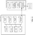
- FIG. 1A is a schematic diagram illustrating a security system 100A in accordance with embodiments of the disclosed technology.
- the security system 100A can communicate with an electric vehicle 10 and/or a mobile device 12.
- the mobile device 12 can include a smartphone, a tablet, a smart watch, a notebook, other type of computing device, etc.
- the electric vehicle 10 can be an electric scooter.
- the system 100A can communicate with the electric vehicle 10 and the mobile device 12 via a wireless network (e.g., Wi-Fi, 3G/4G/5G, Bluetooth, infrared etc.).
- a wireless network e.g., Wi-Fi, 3G/4G/5G, Bluetooth, infrared etc.
- the wireless communication network between the communication components 121 and 107 can be different from the wireless communication network between the communication component 107 and the mobile device 12.
- the electric vehicle 10 includes a processor 109, a memory 111, a battery 113, a motor 115, a first input device 117A, a second input device 117B, a dashboard display 119, and a communication component 121.
- the processor 109 is configured to interact with the memory 111 and other components (e.g., components 113-121) in the electric vehicle 10.
- the memory 111 is coupled to the processor 109 and configured to store instructions for controlling other components or other information in the electric vehicle 10.
- the battery 113 is configured to power the motor 115 such that the motor 115 can move the electric vehicle 10.
- the dashboard display 119 is configured to visually present information to a user (e.g., via a user interfaces shown in Figures 7A-8 ).
- the communication component 121 is configured to communicate with other systems (e.g., the security system 100A) and other devices (e.g., the mobile device 12) in wired or wireless communication based on the configuration between the electric vehicle 10 and other systems/devices.
- the security system 100A includes a processor 101, an input management component 103, a storage component 105, and a communication component 107.
- the processor 101 is configured to control other components of the system 100A and to execute instructions to perform desired operations.
- the input management component 103 is configured to communicate (e.g., via the communication components 107, 121) with the first and second input devices 117A, 117B and accordingly receive passcodes and/or confirmatory input by a user.
- the processor of the vehicle and the processer of the security system may be the same such that the components of the security system are implemented by a single processor.
- the first input device 117A is configured to be operated in a predetermined way such that a user can input a passcode or portion thereof using the first input device.
- the first input device 117A includes a throttle control handle, rotatable in an angle range (e.g., 0-90 degrees, etc.). By rotating the throttle control handle to different angles, the user can input a passcode (which includes one or more passcode components).
- the angle range can be divided into 10 divided ranges. For illustration, if the total angle range for the throttle is 40 degrees, the divided ranges can be divided into 10 ranges: 0-4, 5-8, 9-12, 13-16, 17-20, 21-24, 25-28, 29-32, 33-36 and 37-40 degrees.
- Each divided range represents or corresponds to a unique single-digit number (e.g., 0 to 9). These single-digit numbers can be combined as a passcode component which defines the passcode.
- the passcode components can include a letter, a string, a symbol, etc.
- other detectable ranges of throttle rotation commonly used e.g., 0-90 degrees
- the second input device 117B is configured to enable the user to confirm his/her input encoded by the first input device 117A. For example, when the user holds the first input device 117A at a particular angle or position, the user can then operate the second input device 117B (e.g., a button, handle etc. ) in a predetermined manner (e.g., press the button, squeeze the handle, etc.) to confirm the user's input. In other embodiments, the user's input can be confirmed by other means.
- the second input device can be a brake handle, and when the user holds the first input device 117A in a set position for a time period, then the corresponding input is confirmed.
- the user rotates the throttle to 40 degrees and the user is shown the number 6 on a display.
- the user squeezes the brake handle to accept the number 6.
- the user then rotates the handle to 20 degrees and is shown the number 3 on the display.
- the user then squeezes the handle again to accept the number.
- the code or portion thereof is therefore "63" to which additional numbers can be added in the same manner to complete the code.
- the first and second input devices 117A, 117B are "existing" components of the electric vehicle 10, and therefore perform functions other than inputting/confirming passcodes when the vehicle is operating.
- the brake lever activates the brakes on a scooter.
- the same circuitry that activates the brake lights of the scooter is used to provide a signal to the processor of the security system for use by the security system to indicate that the user has accepted a security code.
- the same circuitry that detects the portion of the throttle for determining how fast to run the motor is used by the security system to show different code values to the user etc.
- Advantages of this arrangement include that the present technology can cooperate with or be implemented in various types of vehicle systems without requiring additional input devices/components.
- the system can include one or more additional input devices configured to receive a user passcode.
- the ECU of the vehicle e.g., the processor 109 of the electric vehicle
- the first and second input device can switch the first and second input device from their "operational modes" to "passcode-input” modes.
- the first/second input devices can be used to input passcodes before the vehicle is turned on again.
- a throttle handle When a throttle handle is in its "operational mode,” it can be rotated to control the throttle (i.e., the power output of the powertrain unit such as motor or engine).
- the throttle handle When the throttle handle is in its "passcode-input mode,” it can be rotated to enter passcodes, as discussed herein.
- a brake handle when a brake handle is in its "operational mode,” it can be squeezed to control the brake of the vehicle.
- the brake handle is in its "passcode-input mode,” it can be used (e.g., as the second input device) to confirm the passcodes entered by the throttle handle.
- the storage component 105 is configured to store, temporarily or permanently, information/data/files/signals associated with the system 100A (e.g., passcodes, relationships between passcode components and the operations/conditions of an input device).
- the storage component 105 stores a reference passcode used to authenticate the received passcode.
- the storage component 105 can be a hard disk drive, flash memory, or other suitable storage means.
- the storage component 105 can be included in the electric vehicle 10.
- the passcode component is shown in the dashboard display 119. Embodiments of a user interface of the dashboard display 119 are to be discussed below with reference to Figure 8 .
- the security system 100A can be implemented by the processor on the vehicle or as a separate component on the vehicle such as a system-on-chip (SOC) system that can perform the functions described above.
- the security system 100A interacts with a remotely located processor.
- the detected component movements or activations can be transmitted to a processor on a smart phone or other device associated with the operator via Bluetooth or infrared that compares the settings with a pre-stored code and the remote processor sends back a signal to unlock the vehicle or feature depending on the settings received.
- the processor of the vehicle may be less likely to be compromised by malicious software to defeat the security feature.
- FIG. 1B is a schematic diagram illustrating a system 100B in accordance with embodiments of the disclosed technology.
- the system 100B is implemented in an electric vehicle.
- the system 100B includes a processor 109, a memory 111, a battery 113, a motor 115, a dashboard display 119 and a communication component 121. These components have functions generally similar to those discussed in Figure 1A .
- the system 100B includes an input management component 103 coupled to the processor 109 and to input devices 117X, 117Y and 117Z.
- the input management component 103 is configured to receive a passcode input by a user via operating the input devices 117X, 117Y and/or 117Z.
- the input device 117X can perform functions similar to those of the first and second input devices 117A, 117B described above in Figure 1A .
- the input device 117Y includes a biometric sensor configured to receive biometric information (e.g., fingerprints, palm prints, voices, iris or retinal images, etc.) from a user. The collected biometric information can be used to further verify the identity of the user.
- the input device 117Y can also be configured to be operated in a predetermined way such that a user can input a passcode.
- the input device 117Y can be a touch pad (which can have a plurality of pressure or optical sensors) used to measure/analyze a user's finger print.
- a user can use his/her finger to draw various lines or patterns on the touch pad, and these various lines or patterns can represent different passcode components.
- the touch pad can be a touch screen.
- the touch pad can include a fingerprint or palm print sensor.
- the input device 117Y can also be configured to be operated in a predetermined way such that a user can input a passcode.
- the input device 117Z can include a sensor configured to measure a status of the system 100B.
- the input device 117Z can be a pressure sensor used to detect whether a user is sitting on a driver seat of the system 100B.
- the user can input multiple passcode components by sitting on the driver seat for different periods of time or at different locations (e.g., left or right side of the driver seat).
- the user can input a passcode and confirm passcode components by operating one or more of the input devices 117X-117Z.
- the input management component 103 is configured to enable a user to set up relationships between passcode components and the operations/conditions of the input devices 117X-117Z.
- the system 100B enables a user to set up the foregoing relationships via the mobile device 12.
- the input management component 103 can be implemented as a software application installed in the mobile device 12. In such embodiments, the input management component 103 communicates with one or more input devices of a vehicle. When a user operates the input devices to enter a passcode for authentication, the input management component 103 receives the operating conditions/statuses of the input devices, and then identifies one or more passcode components so as to form the passcode. The passcode can then be used to authenticate the user.
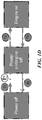
- FIG. 1C is a schematic diagram illustrating multiple status conditions of a vehicle in accordance with embodiments of the disclosed technology.
- the vehicle includes three status conditions, "Power off,” “Power On/engine off,” and “Engine on.”
- the "Power off” status refers to a situation where a main power supply (e.g., a battery) of the vehicle is turned off and only some of the vehicle components is/are operating.
- a wired/wireless communication component of a processor e.g., an Electric Control Unit or Engine Control Unit, ECU
- ECU Electric Control Unit
- the "Power On/engine off” status refers to a situation where a main power supply, an ECU, a Micro Controller Unit or Motor Control Unit (MCU), peripheral components (e.g., lighting components, a dashboard display, etc.) are enabled/turned on, but an engine or a motor (e.g., an electric motor) of the vehicle remains off.
- the "Engine on” status means that the engine or motor of the vehicle is activated/turned on and therefore the vehicle is ready to travel.
- the "engine on/off” can mean “motor on/off,” “powertrain on/off,” “motor enable/disable,” or “powertrain enable/disable”.
- transition T1 includes a user using a key fob (or a keyless control on a mobile phone/smart watch) to transmit a signal regarding unlocking the vehicle, then the vehicle is activated to the "Power on" status from the "Power off” status after receiving the signal.
- a physical lock accommodating a physical key can be disposed on the vehicle. The signal regarding unlocking the vehicle can be transmitted from the physical lock internally when the physical lock in unlocked by the inserted physical key.
- Transition T2 includes, for example, pressing a button (e.g., a "GO" button shown on a dashboard or a mobile device, as shown in Figure 8 ) together with holding a brake lever of the vehicle.
- a button e.g., a "GO" button shown on a dashboard or a mobile device, as shown in Figure 8
- the engine or the motor of the vehicle can be turned on.
- Transition T3 can turn off the engine or the motor of the vehicle by pressing a button or kicking/operating a side stand of the vehicle.
- Transition T4 can turn off power of the vehicle by operating a key fob, a keyless control, etc. In some embodiments, the power can be turned off after a period of time of no operation.
- the present technology can enhance the security of the vehicle by implementing the "security boost" feature in transition T5 or T6, or both.
- transition T5 the present technology can ask a user to enter a passcode (e.g., by operating one or more input devices of the vehicle as described) when the user wants to start the engine or the motor.
- a passcode e.g., by operating one or more input devices of the vehicle as described
- the present technology can also ask the user to enter a passcode (transition T5).
- This arrangement provides higher security level for the vehicle because it requires at least two mechanisms (e.g., keys and passcode that is input by operating one or more vehicle controls or input devices) in order to turn on the power or the engine/motor of the vehicle.
- the controller of the vehicle e.g., the ECU or processor of the vehicle
- the embodiments illustrated in Figure 1C and Figure 1D can have different hardware configurations of the vehicle.
- the vehicle is allowed to "enable” the dashboard (e.g., turn on it so a user can access or read information therefrom) before the "Power on” state
- the embodiments depicted in Figure 1D can be adapted in that vehicle.
- the vehicle does not allow the dashboard to be enabled before the "Power on” state
- the embodiments depicted in Figure 1D can be adapted in the vehicle.
- the user can be banned from having any operation to the vehicle other than entering the passcode.
- a user can turn on the engine by entering the passcode (transition T6) without providing a key fob (transition T6).
- the vehicle can require a user to both present a key fob and enter a correct passcode, before turning on the engine. So the "security boost" feature can be an alternative way to unlock the vehicle when the user forgets where his key, key fob is and/or his mobile device is missing, or the communication components associated with the key fob or the mobile device is malfunctioned.
- the "security boost" feature can be set as to unlock some other features on the vehicle without turning the power of the vehicle on.
- the user can use the same way as described above to enter the passcode during transition T5 in Figure 1D to open the seat cover to access the compartment disposed under the seat cover.
- the features can also include enabling the front light, setting different light pattern of the dashboard or sound profile to the dashboard, etc.
- the vehicle can allow a user to enter more than one set of passcodes to unlock the corresponding features.
- transition T5 can include using biometric information (such as fingerprints, palm prints, face or retina recognition, etc.) to verify a user's identity to access the vehicle.
- biometric information such as fingerprints, palm prints, face or retina recognition, etc.
- the verification could be performed by a mobile phone (which may be wirelessly connected to the vehicle), a setup box mounted on/in the vehicle, the vehicle itself (e.g., a biometric sensor incorporated or embedded in the vehicle), etc.
- FIG. 2A is a schematic diagram illustrating a vehicle 200 and its components that serve as input devices in accordance with embodiments of the disclosed technology.
- the vehicle 200 includes handle bars 201 configured to steer or handle the vehicle 200.
- a throttle 203 is coupled to one end of the handle bars 201 and is configured to produce an electrical signal or move a cable that in turn controls the speed of the vehicle 200.
- a first brake lever 205a is positioned adjacent to the throttle 203 and is configured to control a first brake (e.g., a front wheel brake) of the vehicle 200.
- a second brake level 205b configured to control a second brake (e.g., a rear wheel brake) of the vehicle 200.
- the vehicle 200 includes a side stand 207 positioned in a lower portion of the vehicle 200.
- the side stand 207 is configured to support the vehicle 200 (by contacting the ground) when the vehicle 200 is not moving.
- the vehicle 200 also includes a seat (or a storage cover) 209 that is configured to support a rider and to cover a storage chamber 211 inside the vehicle 200.
- the vehicle 200 includes an adjustable headlight 213 configured to emit light at different angles and/or emit various types of light beams (e.g., high beam or low beam).
- the vehicle 200 further includes a rearview mirror 211 configured to provide a rider rear views of the vehicle 200.
- one or more of the vehicle components discussed above can be used as "input devices" described in the embodiments of the present technology.
- the handle bars 201 can be operated or rotated so to move a front wheel 215 of the vehicle 200 in an angle range (e.g., 100 degrees) along direction A.
- the present technology includes an angle sensor that measures the angle of the handle bars (e.g., the first input device) and provides the measurement to a processor that determines if the detected angle falls into one of a number of defined angle ranges (e.g., 0-9, 10-19, 20-29, 30-39, 40-49, 50-59, 60-69, 70-79, 80-89, and 90-99 degrees), each of which represents a passcode component (e.g., numbers 0-9).
- a passcode component e.g., numbers 09
- the location and/or movement can be measured by an optical or electrical sensor coupled to the handle bars 201. Accordingly, a user can input passcodes or a portion thereof by operating the handle bar 201 (e.g., positioning it at a specific angle).
- the side stand 207 can be operated or rotated along direction B and can be configured to enable a user to input passcodes or confirm a code component by positioning the side stand 207 in a particular positon.
- the throttle 203, the first/second brake levers 205a, 205b, and the storage cover 209 can also be operated in individual angle ranges such that can be configured to enable a user to input passcodes or confirm passcode components in the way similar to those of the handle 201 and the side stand 207 mentioned above.
- the pressure with which a brake lever is squeezed can also be detected and divided into a range (high pressure or less pressure) and used to form a passcode or component thereof.
- the time with which a component is actuated can also be used to enter a code. For example, squeezing the front brake lever for 2 seconds may not generate a passcode but squeezing for 5 seconds may signify a portion of a passcode.
- the particular passcode can be defined by the user using an application on their mobile computing device. For example, the user may request that their secret code comprise turning the handle bars 45 degrees to the right and squeezing the back brake handle for some period of time between 4 and 5 seconds.
- Figure 2B is a schematic diagram illustrating relationships between divided angle ranges and passcode components.
- a total angle range of an input device is 360 degrees.
- the total angle range can be divided into nine individual angle ranges (e.g., 40 degrees), each of which represents a passcode component (e.g., numbers 1-9).
- the corresponding passcode component when the input device is located at its initial position, the corresponding passcode component is set as "0.”
- the total angle range can be divided into different numbers of individual angle ranges, depending on the types of input devices and/or other suitable factors (e.g., the types of passcode components).
- individual angle ranges can vary (e.g., one is 30 degrees and another is 50 degrees), depending on design needs or user preferences.
- the input device can be a "signalized” or "digitalized” input device.
- a controller e.g., an ECU
- processor of the vehicle 200 can use digital signals to control the input device.
- the controller can use voltage signals to control the throttle 203 (e.g., voltage levels correspond to throttle levels).
- the present technology can directly detect the digital signals and then accordingly identifies corresponding passcode components.
- the input device can be an "analog" input device (e.g., a handle bar).
- the present technology uses a sensor (e.g., coupled to a controller of the vehicle) to detect a movement or rotation of the analog input device, and then accordingly identifies corresponding passcode components.
- the storage cover 209 can be locked and require a passcode (e.g., a combination of operations performed on the other input devices) to unlock. Once the storage cover 209 is unlocked, it can then be operated as one of the input devices (e.g., the storage cover 209 can be positioned at various angles/locations, each of which corresponds to a passcode component). This arrangement provides a user a relatively high security level because it requires two set of passcode combinations (which can correspond to the same passcode, in some embodiments) to unlock the vehicle 200.
- a passcode e.g., a combination of operations performed on the other input devices
- the adjustable headlight 213 can also be used to input a code by, for example, turning the high beam on and off in a particular time sequence. Therefore, it can also be configured to enable a user to input passcodes.
- the rear mirror 211 can also be adjusted in a range (e.g., be rotated or moved). Therefore, the rearview mirror 211 can also be used as an input device as described above.
- FIG. 3 is a schematic diagram illustrating a vehicle security management system 300 in accordance with embodiments of the disclosed technology.
- the system 300 can manage/receive passcodes from various groups (e.g., Group A and Group B) of vehicles.
- the system 300 can include (1) an input management component 301 configured to receive passcodes from a vehicle of one of the groups, and (2) a passcode management component 303 configured to manage, maintain, and/or update passcodes for the various groups of vehicles.
- the input management component 301 can have functions similar to those of the input management component 103 discussed above.
- the vehicles in Group A can be the vehicles owned by a company located in area A.
- the vehicles in Group B can be another set of vehicles owned by the same company in area B.
- the present technology enables the company to manage the passcodes for all the vehicles in a centralized, effective fashion.
- a driver can register an account with the company and purchase a rental plan (e.g., a vehicle or battery rental plan) to use vehicle A1 in area A.
- the driver can select a passcode (e.g., by the methods described above, by entering it via his mobile device, etc.).
- the passcode can be given by a server.
- the driver can later purchase another plan (or upgrade his/her existing plan) which allows the driver to use vehicle B1 in area B (e.g., the driver plans to have a business trip in area B).
- the driver can first input a passcode by operating input devices of vehicle A1.
- the input management component 301 receives the passcode (e.g., as indicated by arrow C1).
- the passcode management component 303 stores it and then uploads it to a cloud server 305 (e.g., as indicated by arrow C2).
- the uploaded passcode is then transmitted to, or otherwise be accessible by, vehicle B1 (e.g., as indicated by arrow C3).
- the driver can unlock vehicle B1 by the passcode the driver previously created for vehicle A. This is convenient, secure, and effective for the company and the driver.
- the input management component 301 can receive passcodes of one vehicle (e.g., vehicle A2) via another vehicle (e.g., vehicle A3) in the same vehicle group (e.g., arrow C4 and arrow C1).
- a vehicle can periodically upload a passcode to the cloud server (e.g., arrow C5).
- the passcode management component 303 can be configured to manage/maintain/update passcodes based on user profile, user activities, user preferences, required security levels, vehicle capacities, etc. For example, the passcode management component 303 can verify whether vehicle A1 and vehicle B1 have a same type of input device before transmitting the passcode to vehicle B1. As another example, the passcode management component 303 can transmit the received passcode to another authorized user according to the driver's user profile (e.g., which has a general authorization allowing a family member to use the driver's vehicles).
- the driver's user profile e.g., which has a general authorization allowing a family member to use the driver's vehicles.
- Figures 4A and 4B are schematic diagrams illustrating exemplary data structures used in systems in accordance with embodiments of the disclosed technology.
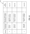
- Figure 4A includes an input-index table 400A showing that the relationships between passcode components (in the illustrated embodiment, single-digit numbers 0-9) and input devices A-X of a vehicle.
- the input-index table 400A can be created and maintained both by an input management component (e.g., the input management component 103).
- the input-index table 400A can be created by an input management component (e.g., the input management component 301) and then be maintained by a passcode management component (e.g., the passcode management component 303).
- the present technology enables a user to enter passcode components 0-9 by operating Input device A alone.
- the present technology also enables a user to enter passcode components 0-9 by operating Input Device B (e.g., a throttle-control handle) and Input Device C (e.g., a button) at the same time or in a predetermined order (e.g., to operate Input Device B first and then Input Device C, or vice versa).
- the present technology enables a user to enter passcode components by operating two or more input devices.
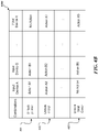
- Figure 4B includes another type of input-index table 400B.
- the input-index table 400B can include various combinations of the operations/status of the input devices A-X of a vehicle. Each of the combinations can correspond to a particular type of unlocking action. For example, combination 401 corresponds to "unlock power" (e.g., transit to "Power on” status) combination 403 corresponds to "unlock engine” (e.g., transit to "Engine on” status) and combination 405 corresponds to "unlock seat cover” for accessing a compartment of the vehicle under the seat cover.
- one or more of the input devices A-X can be a component of a mobile device.
- a user can input a first portion of a passcode via the position of the handlebars of a vehicle, and then input a second portion of the passcode via a touch screen of a smartphone.
- the system can combine the two portions of the passcode and then use the combined passcode to perform an authentication process. Having input devices from multiple sources can accordingly enhance security.
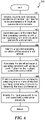
- FIGS. 5 and 6 are flowcharts illustrating methods 500 and 600 in accordance with embodiments of the disclosed technology.
- the method 500 can be used to unlock a vehicle having a first input device and a second input device.
- the method 500 can be implemented by a vehicle, a mobile device, a stand-alone chip set or circuitry, or other types of suitable devices.
- the method 500 starts at block 501 by generating a passcode in response to a detected actuation of a first input device disposed on a vehicle.
- the "detected actuation" can include a rotation of the first input device and/or a holding operation of the first input device.
- the first input device is a throttle, i.e. a throttle-control handle.
- the passcode is input by operating one or more of the input devices in a first predetermined way.
- the passcode is input by rotating the throttle to a particular angle (or positioning the throttle in a particular angle range).
- the particular angle corresponds to a particular passcode component (e.g., 1-9, A-Z, etc.).
- the method 500 comprises: (1) identifying an operational condition of the first input device; (2) generating at least one passcode component in response to the operational condition of the first input device; (3) identifying a confirmatory operation of a second input device; and (4) confirming the generated passcode component in response to the confirmatory operation of the second input device.
- the first operation conditional of the first input device includes rotating the first input device so as to position the first input device at a predetermined angle.
- the passcode component is generated according to the predetermined angle (e.g., Figure 2B ).
- the "operational condition" and the “confirmatory operation” can be from the same device.
- the method 500 can include: (1) identifying a first operational condition (e.g., rotating) of the first input device; (2) generating the passcode component in response to the first operational condition of the first input device; (3) identifying a second operational condition (e.g., holding the first input device for a preset period of time) of the first input device; and (4) confirming the generated passcode component in response to the second operational condition.
- the second operational condition includes positioning the first input device at a predetermined angle for a preset period of time.
- the method 500 can receive a confirmation of the passcode from the second input device (e.g., by the confirmatory operation described above).
- the second input device can be a button, throttle, handle, lever, steering wheel, handle bar, pedal, paddle, shifter, side stand, trunk lid, fuel lid/cap, power plug or other suitable components.
- the second input device is configured to confirm or "enter" a passcode component input by the first input device. For example, when a user operates the first input device (e.g., rotate the throttle), a display (e.g., dashboard display or a display of a mobile device) can present a candidate passcode component to the user.
- the display presents individual passcode components 0 to 9, depending on which angle range the first input device is currently in.
- the user rotates and positions the first input device in a target angle range (which corresponds to a passcode component the user would like to input)
- the user then operates the second input device to confirm the user's input.
- the confirmation is input by operating the second input device in a second predetermined way.
- the confirmation can be a single click of a button.
- the confirmation can be a combination of multiple operations.
- the confirmation can be a user holding the first brake lever 205a and the second brake lever 205b at the same time.
- the confirmation can include a user pulling the first brake lever 205a twice and then pulling the second brake lever 205b once.
- the confirmation can include various combinations of operations of one or more input devices.
- the first input device and the second input device can be the same input device (e.g., with different operations for "passcode component input” and "confirmation”).
- a user can operate the first input device and then maintain the first input device at a location or an angle for a particular period of time (e.g., 2 seconds). After the period of time, the passcode component corresponding to that location or angle is considered “confirmed” and then is entered.
- the method 500 continues to comparing the generated passcode with a reference code stored in a memory disposed in the vehicle.
- the reference code can be stored in other suitable device such as a remote server.
- the method 500 then unlocks one or more features of the vehicle if the generated passcode matches the reference code.
- the one or more features can include an operational state of the vehicle, activating a motor of the vehicle, and/or accessing a compartment of the vehicle.
- the method 500 can switch the first input device to an operational mode (from a password-input mode, for example).
- the method 500 can include receiving a signal (e.g., a user request) regarding unlocking the vehicle before generating the passcode in response to the detected actuation of the first input device disposed on the vehicle.
- the signal can set the first input device in the password-input mode.
- the first input device can include two or more input devices.
- the second input device can include two or more input devices.
- the number of available combinations of input device operations positively correlates to the security level that the present technology can provide. In general, more combinations mean higher security levels.
- the method 500 includes comparing the stored passcode with a reference passcode, and in an event that the stored passcode matches the reference passcode, a signal is produced by a processor to start an engine of the vehicle.
- the passcodes can be compared by an ECU. In other embodiments, the passcodes can be compared by a processor of a mobile device.
- the method 500 includes (a) in an event that the input passcode does not match the reference passcode, presenting an indication via a display of the vehicle showing that the passcode is incorrect; and (b) transmitting a signal (e.g., an alarm signal) to a mobile device associated with the vehicle, alerting that an incorrect passcode has been input.
- a signal e.g., an alarm signal
- the indication can be presented by a dashboard display, a display of a mobile device, etc.
- the alert signal can be transmitted to a portable device or a wearable device. The portable or wearable device can further alarm the user by indications based on light, sound, vibration, etc.
- the method 500 can further include (1) identifying a first operating condition of the first input device according to the first predetermined way; (2) generating a first passcode component in response to the first operating condition; (3) identifying a second operating condition of the first input device according to the first predetermined way; (4) generating a second passcode component in response to the second operating condition; and (5) generating the passcode based at least in part on the first passcode component and the second passcode component.
- the method 500 further includes (i) visually presenting the first passcode component via a display of the vehicle, and (ii) visually presenting the second passcode component via the display of the vehicle.
- the present technology can include a method 600 for setting up a security system for a vehicle.
- the vehicle has a first input device and a second input device.
- the first and second input devices can be separate components.
- the first and second input devices can be a single input device.
- the method 600 can be implemented in a vehicle, a mobile device, a stand-alone chip set or circuitry, a server, or other types of suitable devices.
- the method 600 includes identifying multiple first operating conditions of the first input device to be associated with multiple passcode components (block 601). For example, the method 600 enables a user to set up the relationships between each of the operations (e.g., to be positioned at a location) of the first input device and individual passcode components (e.g., 1-9, A-Z, etc.). At block 603, the method 600 associates each of the identified first operating conditions with a corresponding one of the multiple passcode components.
- the relationships can be stored as a table such as those shown in Figures 4A and 4B .
- the method 600 includes identifying a second operating condition of the second input device (block 605).
- the identified second operating condition is then associated with an input confirmation for the multiple passcode components (block 607).
- the method 600 then enables a user to input the passcode components and then confirm the same by detecting the input confirmation (block 609).
- the input passcode is compared with a reference passcode for authentication of the user. Once authenticated, the security system produces a signal to turn on power of the vehicle or an engine of the vehicle (e.g., as shown in Figure 1C ).
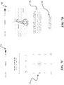
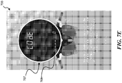
- Figures 7A-7E are screenshots illustrating a user interface 700 of the system in accordance with embodiments of the disclosed technology.
- the user interface 700 can be visually presented on a display of a mobile device (e.g., a smartphone, a tablet, etc.).
- the user interface 700 can be visually presented on any other suitable display such as a dashboard display.
- the user interface 700 enables a user to initiate a setup process for a vehicle security system (e.g., referred to as "security boost protection" in Figure 7A ) by clicking a virtual button 701.
- a vehicle security system e.g., referred to as "security boost protection" in Figure 7A
- the virtual button 701 can be presented to the user after the user initiates an application that can communicate with, or control, an electric vehicle (e.g., a "Gogoro" scooter).
- an electric vehicle e.g., a "Gogoro" scooter.
- the user interface 700 presents a description 702 regarding the vehicle security system, as shown in Figure 7B .
- the description 702 is scrollable to enable the user to view multiple pages of content in the description 702.
- the user interface 700 also provides a virtual start button 703 for the user to click and initiate the setup process.
- the user interface 700 After the user clicks the virtual start button 703, the user interface 700 then presents a virtual keypad 704 for the user to enter a passcode, as shown in Figure 7C .
- the entered passcode is stored and then used as a reference passcode for an authentication process.
- the user interface 700 then prompts for a confirmation 705, as shown in Figure 7D .
- the user interface 700 can also provide a link 706, which enables the user to access further information regarding the vehicle security system.
- the user interface 700 can then initiate an input-device setup process for the user to define relationships between multiple passcode components and the operations/statuses of an input device of the electric vehicle.
- the user interface 700 can present a dashboard-like image 707, which is configured to provide relevant information during the input-device setup process or serves as a tutorial interface.
- the dashboard-like image 707 can include a passcode display area 708 for displaying passcode components.
- the passcode display area 708 is configured to display passcode components (e.g., 4 single-digit numbers, in the illustrated embodiment) during the input-device setup process.
- the passcode display area 708 can also be used to display a passcode during the setup process described above with reference to Figures 7A-7D .
- passcode information entered in the user's mobile device is then sent to the vehicle where it is stored and used in the authentication process.
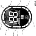
- Figure 8 is a schematic diagram illustrating a user interface 800 of a vehicle in accordance with embodiments of the disclosed technology.
- the user interface 800 can be visually presented on a display (e.g., the dashboard display 119) of a vehicle.
- the user interface 800 can be visually presented in other types of display (e.g., a display of a mobile device).
- the user interface 800 includes eight indication portions 801-808.
- the indication portions 801-808 are configured to visually present the passcode components during the input-device setup process.
- each of the indication portions 801-808 can be visually presented in different colors, at different brightness levels, or at different blinking frequencies.
- the combinations of the visual presentations of the indication portions 801-808 can effectively provide the user which passcode component is being set during the input-device setup process.
- an input device of a vehicle e.g., throttle
- the range can be divided by ten such that each divided degree range (e.g., a 10-degree range) represents a single digit number (e.g., 0 to 9).
- the user interface 800 can present these ten passcode components by using the visual combinations of the indication portions 801-808.
- the user interface 800 can darken all of the indication portions 801-808 to represent digit "0," brighten only the indication portion 801 to indicate digital "1,” brighten only the indication portion 802 to indicate digital "2,” brighten all of the indication portions 801-808 to represent digit "9,” and so on.
- the user interface 800 can provide sufficient visual indication to guide the user through the input-device setup process.
- a 4-letter term "Code” can be displayed in a timer section 810 of the user interface 800.
- a 4-digit passcode which has four single-digit passcode components
- each letter of the term "Code” can be changed accordingly so as to show the four passcode components to the user.
- the 4-letter term "Code” can be displayed in other areas of the user interface 800 (e.g., in an odometer section 812, a mileage section 814, etc.).
- the present technology can have other types of terms (e.g., longer or shorter) to represent a passcode.
- the term "Code” can be displayed in a small font such that it cannot be easily seen by a bystander.
- the security boost feature can be used not only to allow operation of the vehicle but can also be used to unlock features of the vehicle. For example, if a scooter is shared by a father and a teenage son, the security boost feature can be used to allow the father to operate the vehicle at faster speeds than those permitted for the son etc. Similarly, the control of the vehicle unlock by the security boost feature may allow operation in different times of the day such as after 11 p.m. etc.
Landscapes
- Engineering & Computer Science (AREA)
- Mechanical Engineering (AREA)
- Computer Security & Cryptography (AREA)
- Physics & Mathematics (AREA)
- General Physics & Mathematics (AREA)
- Computer Networks & Wireless Communication (AREA)
- Signal Processing (AREA)
- Theoretical Computer Science (AREA)
- Computer Hardware Design (AREA)
- Transportation (AREA)
- Combustion & Propulsion (AREA)
- Chemical & Material Sciences (AREA)
- General Engineering & Computer Science (AREA)
- Software Systems (AREA)
- General Health & Medical Sciences (AREA)
- Bioethics (AREA)
- Health & Medical Sciences (AREA)
- Lock And Its Accessories (AREA)
- Control Of Driving Devices And Active Controlling Of Vehicle (AREA)
- Auxiliary Drives, Propulsion Controls, And Safety Devices (AREA)
Description
- The present application claims the benefit of and priority to
U.S. Provisional Application No. 62/482,119, filed April 5, 2017 - The present technology is directed to systems and methods for maintaining security of a vehicle. More particularly, the present technology is directed to systems and methods for locking or unlocking mechanical or other features of a vehicle by operating one or more existing components thereof.
- User authentication systems for vehicles are used to prevent unauthorized users from accessing, or operating, or stealing vehicles. Traditional user authentication systems include physical keys or radio frequency fobs. Such traditional systems require authorized users to insert the keys into, or present the fobs to, the vehicle to complete an authentication process. If a key for a traditional system is lost and found by an unauthorized user, the vehicle will grant access to the unauthorized user. In other words, the security of the traditional system can be easily compromised by simply losing the keys or fobs. Therefore, it is advantageous to have an improved system to address this issue.
US 2008/150682 A1 refers to a method for operating a vehicle, comprising: comparing the generated passcode with a reference code stored in a memory disposed in the vehicle, and unlocking one or more features of the vehicle if the generated passcode matches the reference code, wherein a first input device preferably is a main switch, a front brake or a rear brake.
CN 105 869 237 A andUS 2017/116800 A1 disclose a keyless password device of locking doors, comprising: comparing the generated passcode with a reference code stored in a memory disposed in the vehicle, and unlocking one or more features of the vehicle if the generated passcode matches the reference code
DE 44 24 879 A1 discloses a method for avoiding unauthorized starting of a motor of a vehicle, wherein a vehicle can only be started by simultaneously operating several input devices.
US 2016/371907 A1 discloses keys and locks for vehicle to open and start vehicle, wherein a passcode can be input via an electronic passcode key input device.
US 2009/021361 A1 refers to a method for putting a vehicle in a usable state when a smart key cannot be used, wherein the method comprises comparing the generated passcode with a reference code stored in a memory disposed in the vehicle, and unlocking one or more features of the vehicle if the generated passcode matches the reference code. - The present invention provides a method for operating a vehicle according to
claim 1, a vehicle according toclaim 7, and a system for unlocking a vehicle according toclaim 12. The dependent claims show further examples of said method and vehicle, respectively. - -
- -
- Embodiments of the disclosed technology will be described and explained through the use of the accompanying drawings.
-
Figure 1A is a schematic diagram illustrating a system in accordance with embodiments of the disclosed technology. -
Figure 1B is a schematic diagram illustrating a system in accordance with embodiments of the disclosed technology. -
Figure 1C is a schematic diagram illustrating multiple statuses of a vehicle in accordance with embodiments of the disclosed technology. -
Figure 1D is a schematic diagram illustrating multiple statuses of a vehicle in accordance with embodiments of the disclosed technology. -
Figure 2A is a schematic diagram illustrating a vehicle and its components that can serve as input devices in accordance with embodiments of the disclosed technology. -
Figure 2B is a schematic diagram illustrating relationships between divided angle ranges and passcode components in accordance with embodiments of the disclosed technology. -
Figure 3 is a schematic diagram illustrating a vehicle security system in accordance with embodiments of the disclosed technology. -
Figures 4A and4B are schematic diagrams illustrating data structure used in systems in accordance with embodiments of the disclosed technology. -
Figure 5 is a flowchart illustrating a method in accordance with embodiments of the disclosed technology. -
Figure 6 is a flowchart illustrating a method in accordance with embodiments of the disclosed technology. -
Figures 7A-7E are screenshots illustrating a user interface of the system in accordance with embodiments of the disclosed technology. -
Figure 8 is a schematic diagram illustrating a user interface of a vehicle in accordance with embodiments of the disclosed technology. - The drawings are not necessarily drawn to scale. For example, the dimensions of some of the elements in the figures may be expanded or reduced to help improve the understanding of various embodiments. Similarly, some components and/or operations may be separated into different blocks or combined into a single block for the purposes of discussion of some of the embodiments. Moreover, although specific embodiments have been shown by way of example in the drawings and described in detail below, one skilled in the art will recognize that modifications, equivalents, and alternatives will fall within the scope of the appended claims.
- In this description, references to "some embodiments," "one embodiment," or the like, mean that the particular feature, function, structure or characteristic being described is included in at least one embodiment of the disclosed technology. Occurrences of such phrases in this specification do not necessarily all refer to the same embodiment. On the other hand, the embodiments referred to are not necessarily mutually exclusive.
- The present disclosure relates to a method and system for unlocking certain feature(s) on a vehicle (e.g., a scooter, an electric scooter, a gas-fueled or an electric motorcycle, a four-wheeled gas-fueled/electric vehicle, etc.) by operating a combination of existing components of the vehicle. The present technology enables a user to set up a combination of how to operate these components (e.g., as a passcode), and then use the combination to unlock mechanical or other features of the vehicle. The present technology enables a user to select one or more "input devices" of the vehicle as part of the combination. The input devices are existing components of the vehicle and includes a rotatable throttle-control handle (or "throttle handle"). Operating the input devices in a predetermined way (e.g., rotate), defines a passcode that a programmed processor or other logic circuit either in or logically associated with the system can compare with a reference passcode. If the received passcode matches the reference passcode, the system grants the user access to the vehicle. In some embodiments, the status of a component can be called as an "operational condition." For example, a component can have 10 operational conditions, each of which can correspond to a passcode digit.
- In some embodiments, the system can be implemented as a supplemental security mechanism in addition to a traditional authentication system (e.g., using physical keys or fobs).
- In some embodiments, the present technology can be implemented as a stand-alone system that can be installed in a vehicle (embodiments to be discussed in detail with reference to
Figure 1A ). In some embodiments, the present technology can be implemented as a part of a vehicle control system (embodiments to be discussed in detail with reference toFigure 1B ). In other embodiments, the present technology can be implemented in a mobile device (e.g., a smartphone with an app installed) that is capable of communicating with a vehicle. - One aspect of the present technology includes providing a vehicle security system that enables a user to manage multiple vehicles in a network (e.g., fleet vehicles of a company, a group of vehicles of a family, vehicles of a vehicle-rental company, etc.). The present technology enables a user to manage the accessibility of the vehicles in various groups via a cloud server. For example, the user can issue different passcodes for authorized drivers who purchase different plans (e.g., plan A allows a driver to ride a scooter at a higher speed than plan B). The vehicles in the network can also communicate with one another regarding passcodes (e.g., share most updated passcodes). Such embodiments are discussed in further detail below with reference to
Figure 3 . - Another aspect of the present technology enables a user to create (and/or frequently update) his/her own combinations of passcodes so as to enhance vehicle security. For example, the present system enables the user to pick a first input device of a vehicle as a component to input passcodes. For example, the user can use a throttle handle of a scooter to enter a passcode by rotating/positioning the throttle handle at different angles/locations. Assuming that the throttle handle can be rotated in a range of 180 degrees, then the range can be divided by ten such that each divided degree range (e.g., a 18-degree range) represents a single digit number (e.g., 0 to 9). In some embodiments, the degree range can be divided by other numbers (e.g., 16 or 26) and accordingly the positions of the throttle in each divided range can represent other characters or symbols (e.g., hexadecimal numbers or letters of the English alphabet) that can be used to form a passcode. In some embodiments, each degree range can be different due to the characteristics of the first input device (e.g., sensitivity or responsiveness of the first input device can vary in different degree ranges). In some embodiments, there can be various sensors or electronic components (e.g., a variable resistor, a potentiometer, etc.) positioned at multiple locations such that the location of the first input device can be sensed or detected. For example, in some embodiments, the throttle handle can be an electronic throttle. In such embodiments, an output voltage or current of the throttle handle can vary corresponding to an angle of rotation of the throttle handle. In some other embodiments, a hall-effect sensor can be disposed on the throttle handle, and the hall-effect sensor can monitor the rotation of the throttle handle (i.e., the relative movements between the stationary part and the rotatable part of the throttle handle) by sensing magnetic-field variation (e.g., caused by the rotation). Based on the sensed location of the first input device, a passcode can accordingly be determined.
- In some embodiments, the system also enables the user to pick a second input device to confirm all or portions of a passcode or enter an additional passcode. For example, the user can use a brake lever (or a brake pedal) to confirm passcode component that is input by the first input device (e.g., a "confirmatory" or "confirmational" operation). In other embodiments, the passcode component can be confirmed by other means (e.g., the confirmatory operation can be, holding the first input device for a certain time period). Relevant embodiments are to be discussed in detail below with reference to
Figures 4A and4B . - The present technology includes providing a user interface to facilitate a user's input of a passcode or setting up passcode components (e.g., numbers, letters, symbols, etc.) corresponding to specific operations or conditions of a vehicle component (e.g., as part of an "input device" mentioned above). Examples of the user interface are to be discussed below with reference to
Figures 7A-8 . - In some embodiments, the present technology enables a user to determine a security level of a vehicle. For example, the present technology can provide recommendations to the user regarding whether to enable an "enhanced security" or "security boost" feature (e.g., using a passcode to unlock the vehicle in addition to a physical lock) of the vehicle. In some embodiments, the recommendations can be based on information such as user profile, a current location of the vehicle, associated crime rates of a location, news associated with a location (e.g., a vehicle was reported stolen last night near a location), etc.
- In some embodiments, the recommendations are transmitted to the user via a user mobile device. Once the user decides to enable the "security boost" features, the user is invited to enter the passcode for accessing the vehicle from the mobile device (e.g., a user interface for entering the passcode; this can be an application running on the mobile phone; detailed embodiments are discussed with respect to
Figures 7A-7D ), and then the passcode can be sent to the vehicle and be stored as a reference code for security verification. In some embodiments, a default configuration is to enable the security boost feature, and the passcode can be stored in the mobile device (e.g., to "remind" the user what the passcode is) and/or in the vehicle (as the reference code for security verification). In some embodiments, the default configuration can be determined based on the user's insurance policy for the vehicle. In some embodiments, the present technology can generate a report summarizing the security features of a vehicle and transmit the report to a user's insurance provider. - In some embodiments, the present technology determines whether to activate the security boost feature based on an available energy level of a vehicle. For example, when the available energy level is lower than a first threshold (e.g., 5% of a full capacity), the present technology disables the security boost feature. In some embodiments, when the available energy level reaches a second threshold, the present technology sends a notification to a user and recommends that the user adjust a current security configuration. In some embodiments, the present technology includes a backup, independent power source (e.g., a battery) configured to make sure that the security boost feature can be implemented even when the available energy level of the vehicle is too low to properly operate the vehicle. In some embodiments, there can be a "controller battery" or "ECU battery" configured to provide power to a controller or an ECU (electric control unit or engine control unit) of the vehicle, when a "main battery" (e.g., which is configured to power an electric motor of the vehicle) of the vehicle is switched off. In some embodiments, the "main battery" can be used to charge the "controller battery," so as to make sure the "controller battery" has sufficient power to support the operation of the controller or ECU.
- In some embodiments, the present technology enables a user to store/upload a picture, a description and/or other suitable information such as a hint regarding the passcode/combination he or she created, just in case the user forgets the combination. In some embodiments, the stored/upload information can be accessible via a user's mobile device.
-
Figure 1A is a schematic diagram illustrating asecurity system 100A in accordance with embodiments of the disclosed technology. As shown, thesecurity system 100A can communicate with anelectric vehicle 10 and/or amobile device 12. In some embodiments, themobile device 12 can include a smartphone, a tablet, a smart watch, a notebook, other type of computing device, etc. In some embodiments, theelectric vehicle 10 can be an electric scooter. In some embodiments, thesystem 100A can communicate with theelectric vehicle 10 and themobile device 12 via a wireless network (e.g., Wi-Fi, 3G/4G/5G, Bluetooth, infrared etc.). In some embodiments, the wireless communication network between thecommunication components communication component 107 and the mobile device 12.As shown, theelectric vehicle 10 includes aprocessor 109, amemory 111, abattery 113, amotor 115, afirst input device 117A, asecond input device 117B, adashboard display 119, and acommunication component 121. Theprocessor 109 is configured to interact with thememory 111 and other components (e.g., components 113-121) in theelectric vehicle 10. Thememory 111 is coupled to theprocessor 109 and configured to store instructions for controlling other components or other information in theelectric vehicle 10. Thebattery 113 is configured to power themotor 115 such that themotor 115 can move theelectric vehicle 10. Thedashboard display 119 is configured to visually present information to a user (e.g., via a user interfaces shown inFigures 7A-8 ). Thecommunication component 121 is configured to communicate with other systems (e.g., thesecurity system 100A) and other devices (e.g., the mobile device 12) in wired or wireless communication based on the configuration between theelectric vehicle 10 and other systems/devices. - As shown in
Figure 1A , thesecurity system 100A includes aprocessor 101, aninput management component 103, astorage component 105, and acommunication component 107. Theprocessor 101 is configured to control other components of thesystem 100A and to execute instructions to perform desired operations. Theinput management component 103 is configured to communicate (e.g., via thecommunication components 107, 121) with the first andsecond input devices - In the illustrated embodiments, the
first input device 117A is configured to be operated in a predetermined way such that a user can input a passcode or portion thereof using the first input device. Thefirst input device 117A includes a throttle control handle, rotatable in an angle range (e.g., 0-90 degrees, etc.). By rotating the throttle control handle to different angles, the user can input a passcode (which includes one or more passcode components). In this embodiment, the angle range can be divided into 10 divided ranges. For illustration, if the total angle range for the throttle is 40 degrees, the divided ranges can be divided into 10 ranges: 0-4, 5-8, 9-12, 13-16, 17-20, 21-24, 25-28, 29-32, 33-36 and 37-40 degrees. Each divided range represents or corresponds to a unique single-digit number (e.g., 0 to 9). These single-digit numbers can be combined as a passcode component which defines the passcode. In some embodiments, the passcode components can include a letter, a string, a symbol, etc. As can be appreciated, other detectable ranges of throttle rotation commonly used (e.g., 0-90 degrees) can be similarly detected and associated with different input values. - In some embodiments, the
second input device 117B is configured to enable the user to confirm his/her input encoded by thefirst input device 117A. For example, when the user holds thefirst input device 117A at a particular angle or position, the user can then operate thesecond input device 117B (e.g., a button, handle etc. ) in a predetermined manner (e.g., press the button, squeeze the handle, etc.) to confirm the user's input. In other embodiments, the user's input can be confirmed by other means. For example, the second input device can be a brake handle, and when the user holds thefirst input device 117A in a set position for a time period, then the corresponding input is confirmed. For example, the user rotates the throttle to 40 degrees and the user is shown thenumber 6 on a display. The user squeezes the brake handle to accept thenumber 6. The user then rotates the handle to 20 degrees and is shown thenumber 3 on the display. The user then squeezes the handle again to accept the number. The code or portion thereof is therefore "63" to which additional numbers can be added in the same manner to complete the code. - The first and
second input devices electric vehicle 10, and therefore perform functions other than inputting/confirming passcodes when the vehicle is operating. For example, the brake lever activates the brakes on a scooter. The same circuitry that activates the brake lights of the scooter is used to provide a signal to the processor of the security system for use by the security system to indicate that the user has accepted a security code. Similarly, the same circuitry that detects the portion of the throttle for determining how fast to run the motor is used by the security system to show different code values to the user etc. Advantages of this arrangement include that the present technology can cooperate with or be implemented in various types of vehicle systems without requiring additional input devices/components. In other embodiments, however, the system can include one or more additional input devices configured to receive a user passcode. In some embodiments, when the vehicle is turned off, the ECU of the vehicle (e.g., theprocessor 109 of the electric vehicle 10) can switch the first and second input device from their "operational modes" to "passcode-input" modes. By this arrangement, the first/second input devices can be used to input passcodes before the vehicle is turned on again. When a throttle handle is in its "operational mode," it can be rotated to control the throttle (i.e., the power output of the powertrain unit such as motor or engine). When the throttle handle is in its "passcode-input mode," it can be rotated to enter passcodes, as discussed herein. As another example, when a brake handle is in its "operational mode," it can be squeezed to control the brake of the vehicle. When the brake handle is in its "passcode-input mode," it can be used (e.g., as the second input device) to confirm the passcodes entered by the throttle handle. - Once a passcode is received by the
input management component 103, the passcode is stored in thestorage component 105. Thestorage component 105 is configured to store, temporarily or permanently, information/data/files/signals associated with thesystem 100A (e.g., passcodes, relationships between passcode components and the operations/conditions of an input device). Thestorage component 105 stores a reference passcode used to authenticate the received passcode. In some embodiments, thestorage component 105 can be a hard disk drive, flash memory, or other suitable storage means. In some embodiments, thestorage component 105 can be included in theelectric vehicle 10. When a user inputs a passcode component, the passcode component is shown in thedashboard display 119. Embodiments of a user interface of thedashboard display 119 are to be discussed below with reference toFigure 8 . - In some embodiments, the
security system 100A can be implemented by the processor on the vehicle or as a separate component on the vehicle such as a system-on-chip (SOC) system that can perform the functions described above. In some embodiments, thesecurity system 100A interacts with a remotely located processor. For example, the detected component movements or activations can be transmitted to a processor on a smart phone or other device associated with the operator via Bluetooth or infrared that compares the settings with a pre-stored code and the remote processor sends back a signal to unlock the vehicle or feature depending on the settings received. In this way, the processor of the vehicle may be less likely to be compromised by malicious software to defeat the security feature. -
Figure 1B is a schematic diagram illustrating asystem 100B in accordance with embodiments of the disclosed technology. Thesystem 100B is implemented in an electric vehicle. Thesystem 100B includes aprocessor 109, amemory 111, abattery 113, amotor 115, adashboard display 119 and acommunication component 121. These components have functions generally similar to those discussed inFigure 1A . Thesystem 100B includes aninput management component 103 coupled to theprocessor 109 and to inputdevices input management component 103 is configured to receive a passcode input by a user via operating theinput devices - The
input device 117X can perform functions similar to those of the first andsecond input devices Figure 1A . Theinput device 117Y includes a biometric sensor configured to receive biometric information (e.g., fingerprints, palm prints, voices, iris or retinal images, etc.) from a user. The collected biometric information can be used to further verify the identity of the user. In some embodiments, theinput device 117Y can also be configured to be operated in a predetermined way such that a user can input a passcode. For example, theinput device 117Y can be a touch pad (which can have a plurality of pressure or optical sensors) used to measure/analyze a user's finger print. In this embodiment, a user can use his/her finger to draw various lines or patterns on the touch pad, and these various lines or patterns can represent different passcode components. In some embodiments, the touch pad can be a touch screen. In some embodiments, the touch pad can include a fingerprint or palm print sensor. - In some embodiments, the
input device 117Y can also be configured to be operated in a predetermined way such that a user can input a passcode. Theinput device 117Z can include a sensor configured to measure a status of thesystem 100B. For example, theinput device 117Z can be a pressure sensor used to detect whether a user is sitting on a driver seat of thesystem 100B. In such embodiments, the user can input multiple passcode components by sitting on the driver seat for different periods of time or at different locations (e.g., left or right side of the driver seat). In other embodiments, the user can input a passcode and confirm passcode components by operating one or more of theinput devices 117X-117Z. - In some embodiments, the
input management component 103 is configured to enable a user to set up relationships between passcode components and the operations/conditions of theinput devices 117X-117Z. In some embodiments, thesystem 100B enables a user to set up the foregoing relationships via themobile device 12. In some embodiments, theinput management component 103 can be implemented as a software application installed in themobile device 12. In such embodiments, theinput management component 103 communicates with one or more input devices of a vehicle. When a user operates the input devices to enter a passcode for authentication, theinput management component 103 receives the operating conditions/statuses of the input devices, and then identifies one or more passcode components so as to form the passcode. The passcode can then be used to authenticate the user. -
Figure 1C is a schematic diagram illustrating multiple status conditions of a vehicle in accordance with embodiments of the disclosed technology. As shown, the vehicle includes three status conditions, "Power off," "Power On/engine off," and "Engine on." In some embodiments, the "Power off" status refers to a situation where a main power supply (e.g., a battery) of the vehicle is turned off and only some of the vehicle components is/are operating. For example, a wired/wireless communication component of a processor (e.g., an Electric Control Unit or Engine Control Unit, ECU) can be in a stand-by mode to receive signals, such as unlocking signals from a key fob or from a mobile device. In some embodiments, the "Power On/engine off" status refers to a situation where a main power supply, an ECU, a Micro Controller Unit or Motor Control Unit (MCU), peripheral components (e.g., lighting components, a dashboard display, etc.) are enabled/turned on, but an engine or a motor (e.g., an electric motor) of the vehicle remains off. In some embodiments, the "Engine on" status means that the engine or motor of the vehicle is activated/turned on and therefore the vehicle is ready to travel. In some embodiments, the "engine on/off" can mean "motor on/off," "powertrain on/off," "motor enable/disable," or "powertrain enable/disable". - In the illustrated embodiments shown in
Figure 1C , the vehicle can change status through transitions T1-T6. For example, transition T1 includes a user using a key fob (or a keyless control on a mobile phone/smart watch) to transmit a signal regarding unlocking the vehicle, then the vehicle is activated to the "Power on" status from the "Power off" status after receiving the signal. In some embodiments, a physical lock accommodating a physical key can be disposed on the vehicle. The signal regarding unlocking the vehicle can be transmitted from the physical lock internally when the physical lock in unlocked by the inserted physical key. Transition T2 includes, for example, pressing a button (e.g., a "GO" button shown on a dashboard or a mobile device, as shown inFigure 8 ) together with holding a brake lever of the vehicle. Through transition T2, the engine or the motor of the vehicle can be turned on. Transition T3 can turn off the engine or the motor of the vehicle by pressing a button or kicking/operating a side stand of the vehicle. Transition T4 can turn off power of the vehicle by operating a key fob, a keyless control, etc. In some embodiments, the power can be turned off after a period of time of no operation. - The present technology can enhance the security of the vehicle by implementing the "security boost" feature in transition T5 or T6, or both. For example, in transition T5, the present technology can ask a user to enter a passcode (e.g., by operating one or more input devices of the vehicle as described) when the user wants to start the engine or the motor. As another example depicted in
Figure 1D , when a user wants to turn on the power of the vehicle (e.g., indicated as transition T1), the present technology can also ask the user to enter a passcode (transition T5). This arrangement provides higher security level for the vehicle because it requires at least two mechanisms (e.g., keys and passcode that is input by operating one or more vehicle controls or input devices) in order to turn on the power or the engine/motor of the vehicle. The controller of the vehicle (e.g., the ECU or processor of the vehicle) may switch the first/second input devices from their "operational modes" to passcode-input modes" during transition T4 or T1, and switch the modes back to their operational modes during transition T2 (e.g., in the embodiments corresponding toFigure 1C ) or in the status condition "power on/engine off" (e.g., in the embodiments corresponding toFigure 1D ). - It is noted the embodiments illustrated in
Figure 1C andFigure 1D can have different hardware configurations of the vehicle. For example, if the vehicle is allowed to "enable" the dashboard (e.g., turn on it so a user can access or read information therefrom) before the "Power on" state, then the embodiments depicted inFigure 1D can be adapted in that vehicle. In some embodiments, if the vehicle does not allow the dashboard to be enabled before the "Power on" state, then the embodiments depicted inFigure 1D can be adapted in the vehicle. The user can be banned from having any operation to the vehicle other than entering the passcode. In some embodiments, a user can turn on the engine by entering the passcode (transition T6) without providing a key fob (transition T6). In some embodiments, the vehicle can require a user to both present a key fob and enter a correct passcode, before turning on the engine. So the "security boost" feature can be an alternative way to unlock the vehicle when the user forgets where his key, key fob is and/or his mobile device is missing, or the communication components associated with the key fob or the mobile device is malfunctioned. - In some embodiment, the "security boost" feature can be set as to unlock some other features on the vehicle without turning the power of the vehicle on. For example, the user can use the same way as described above to enter the passcode during transition T5 in
Figure 1D to open the seat cover to access the compartment disposed under the seat cover. The features can also include enabling the front light, setting different light pattern of the dashboard or sound profile to the dashboard, etc. In some embodiments, the vehicle can allow a user to enter more than one set of passcodes to unlock the corresponding features. - In some embodiments, transition T5 can include using biometric information (such as fingerprints, palm prints, face or retina recognition, etc.) to verify a user's identity to access the vehicle. In some embodiments, the verification could be performed by a mobile phone (which may be wirelessly connected to the vehicle), a setup box mounted on/in the vehicle, the vehicle itself (e.g., a biometric sensor incorporated or embedded in the vehicle), etc.
-
Figure 2A is a schematic diagram illustrating avehicle 200 and its components that serve as input devices in accordance with embodiments of the disclosed technology. Thevehicle 200 includes handle bars 201 configured to steer or handle thevehicle 200. As shown, athrottle 203 is coupled to one end of the handle bars 201 and is configured to produce an electrical signal or move a cable that in turn controls the speed of thevehicle 200. As shown, afirst brake lever 205a is positioned adjacent to thethrottle 203 and is configured to control a first brake (e.g., a front wheel brake) of thevehicle 200. At the other end of the handle bars 201 is asecond brake level 205b configured to control a second brake (e.g., a rear wheel brake) of thevehicle 200. - The
vehicle 200 includes aside stand 207 positioned in a lower portion of thevehicle 200. The side stand 207 is configured to support the vehicle 200 (by contacting the ground) when thevehicle 200 is not moving. Thevehicle 200 also includes a seat (or a storage cover) 209 that is configured to support a rider and to cover astorage chamber 211 inside thevehicle 200. As shown, thevehicle 200 includes anadjustable headlight 213 configured to emit light at different angles and/or emit various types of light beams (e.g., high beam or low beam). Thevehicle 200 further includes arearview mirror 211 configured to provide a rider rear views of thevehicle 200. In various embodiments, one or more of the vehicle components discussed above can be used as "input devices" described in the embodiments of the present technology. - For example (the example is not covered by the claim set but provided as an additional information), the handle bars 201 can be operated or rotated so to move a
front wheel 215 of thevehicle 200 in an angle range (e.g., 100 degrees) along direction A. The present technology includes an angle sensor that measures the angle of the handle bars (e.g., the first input device) and provides the measurement to a processor that determines if the detected angle falls into one of a number of defined angle ranges (e.g., 0-9, 10-19, 20-29, 30-39, 40-49, 50-59, 60-69, 70-79, 80-89, and 90-99 degrees), each of which represents a passcode component (e.g., numbers 0-9). In some embodiments, the location and/or movement can be measured by an optical or electrical sensor coupled to the handle bars 201. Accordingly, a user can input passcodes or a portion thereof by operating the handle bar 201 (e.g., positioning it at a specific angle). - Similarly, the side stand 207 can be operated or rotated along direction B and can be configured to enable a user to input passcodes or confirm a code component by positioning the side stand 207 in a particular positon. The
throttle 203, the first/second brake levers storage cover 209 can also be operated in individual angle ranges such that can be configured to enable a user to input passcodes or confirm passcode components in the way similar to those of thehandle 201 and the side stand 207 mentioned above. For example, the pressure with which a brake lever is squeezed can also be detected and divided into a range (high pressure or less pressure) and used to form a passcode or component thereof. Similarly, the time with which a component is actuated can also be used to enter a code. For example, squeezing the front brake lever for 2 seconds may not generate a passcode but squeezing for 5 seconds may signify a portion of a passcode. The particular passcode can be defined by the user using an application on their mobile computing device. For example, the user may request that their secret code comprise turning the handle bars 45 degrees to the right and squeezing the back brake handle for some period of time between 4 and 5 seconds. -
Figure 2B is a schematic diagram illustrating relationships between divided angle ranges and passcode components. In the illustrated embodiments, a total angle range of an input device is 360 degrees. The total angle range can be divided into nine individual angle ranges (e.g., 40 degrees), each of which represents a passcode component (e.g., numbers 1-9). In the illustrated embodiments, when the input device is located at its initial position, the corresponding passcode component is set as "0." In other embodiments, the total angle range can be divided into different numbers of individual angle ranges, depending on the types of input devices and/or other suitable factors (e.g., the types of passcode components). In some embodiments, individual angle ranges can vary (e.g., one is 30 degrees and another is 50 degrees), depending on design needs or user preferences. - In some embodiments, the input device (e.g., throttle 203) can be a "signalized" or "digitalized" input device. In such embodiments, a controller (e.g., an ECU) or processor of the
vehicle 200 can use digital signals to control the input device. For example, the controller can use voltage signals to control the throttle 203 (e.g., voltage levels correspond to throttle levels). In such embodiments, the present technology can directly detect the digital signals and then accordingly identifies corresponding passcode components. - In some embodiments, the input device can be an "analog" input device (e.g., a handle bar). In such embodiments, the present technology uses a sensor (e.g., coupled to a controller of the vehicle) to detect a movement or rotation of the analog input device, and then accordingly identifies corresponding passcode components.
- In some embodiments, the
storage cover 209 can be locked and require a passcode (e.g., a combination of operations performed on the other input devices) to unlock. Once thestorage cover 209 is unlocked, it can then be operated as one of the input devices (e.g., thestorage cover 209 can be positioned at various angles/locations, each of which corresponds to a passcode component). This arrangement provides a user a relatively high security level because it requires two set of passcode combinations (which can correspond to the same passcode, in some embodiments) to unlock thevehicle 200. - In some examples (not covered by the claim set but provided as additional information), the
adjustable headlight 213 can also be used to input a code by, for example, turning the high beam on and off in a particular time sequence. Therefore, it can also be configured to enable a user to input passcodes. Similarly, in some examples (not covered by the claim set but provided as additional information), therear mirror 211 can also be adjusted in a range (e.g., be rotated or moved). Therefore, therearview mirror 211 can also be used as an input device as described above. -
Figure 3 is a schematic diagram illustrating a vehiclesecurity management system 300 in accordance with embodiments of the disclosed technology. As shown inFigure 3 , thesystem 300 can manage/receive passcodes from various groups (e.g., Group A and Group B) of vehicles. Thesystem 300 can include (1) aninput management component 301 configured to receive passcodes from a vehicle of one of the groups, and (2) apasscode management component 303 configured to manage, maintain, and/or update passcodes for the various groups of vehicles. Theinput management component 301 can have functions similar to those of theinput management component 103 discussed above. - For example, the vehicles in Group A (e.g., vehicle A1, A2, and A3) can be the vehicles owned by a company located in area A. The vehicles in Group B can be another set of vehicles owned by the same company in area B. The present technology enables the company to manage the passcodes for all the vehicles in a centralized, effective fashion. For example, a driver can register an account with the company and purchase a rental plan (e.g., a vehicle or battery rental plan) to use vehicle A1 in area A. In some embodiments, the driver can select a passcode (e.g., by the methods described above, by entering it via his mobile device, etc.). In some embodiments, the passcode can be given by a server. The driver can later purchase another plan (or upgrade his/her existing plan) which allows the driver to use vehicle B1 in area B (e.g., the driver plans to have a business trip in area B). The driver can first input a passcode by operating input devices of vehicle A1. The
input management component 301 receives the passcode (e.g., as indicated by arrow C1). Then thepasscode management component 303 stores it and then uploads it to a cloud server 305 (e.g., as indicated by arrow C2). The uploaded passcode is then transmitted to, or otherwise be accessible by, vehicle B1 (e.g., as indicated by arrow C3). By this arrangement, the driver can unlock vehicle B1 by the passcode the driver previously created for vehicle A. This is convenient, secure, and effective for the company and the driver. - In some embodiments, the
input management component 301 can receive passcodes of one vehicle (e.g., vehicle A2) via another vehicle (e.g., vehicle A3) in the same vehicle group (e.g., arrow C4 and arrow C1). In some embodiments, a vehicle can periodically upload a passcode to the cloud server (e.g., arrow C5). - In some embodiments, the
passcode management component 303 can be configured to manage/maintain/update passcodes based on user profile, user activities, user preferences, required security levels, vehicle capacities, etc. For example, thepasscode management component 303 can verify whether vehicle A1 and vehicle B1 have a same type of input device before transmitting the passcode to vehicle B1. As another example, thepasscode management component 303 can transmit the received passcode to another authorized user according to the driver's user profile (e.g., which has a general authorization allowing a family member to use the driver's vehicles). -
Figures 4A and4B are schematic diagrams illustrating exemplary data structures used in systems in accordance with embodiments of the disclosed technology.Figure 4A includes an input-index table 400A showing that the relationships between passcode components (in the illustrated embodiment, single-digit numbers 0-9) and input devices A-X of a vehicle. In some embodiments, the input-index table 400A can be created and maintained both by an input management component (e.g., the input management component 103). In other embodiments, the input-index table 400A can be created by an input management component (e.g., the input management component 301) and then be maintained by a passcode management component (e.g., the passcode management component 303). - As shown in
Figure 4A , the present technology enables a user to enter passcode components 0-9 by operating Input device A alone. The present technology also enables a user to enter passcode components 0-9 by operating Input Device B (e.g., a throttle-control handle) and Input Device C (e.g., a button) at the same time or in a predetermined order (e.g., to operate Input Device B first and then Input Device C, or vice versa). In some embodiments, the present technology enables a user to enter passcode components by operating two or more input devices. -
Figure 4B includes another type of input-index table 400B. In such embodiments, the input-index table 400B can include various combinations of the operations/status of the input devices A-X of a vehicle. Each of the combinations can correspond to a particular type of unlocking action. For example,combination 401 corresponds to "unlock power" (e.g., transit to "Power on" status)combination 403 corresponds to "unlock engine" (e.g., transit to "Engine on" status) andcombination 405 corresponds to "unlock seat cover" for accessing a compartment of the vehicle under the seat cover. In some embodiments, one or more of the input devices A-X can be a component of a mobile device. For example, a user can input a first portion of a passcode via the position of the handlebars of a vehicle, and then input a second portion of the passcode via a touch screen of a smartphone. In such embodiments, the system can combine the two portions of the passcode and then use the combined passcode to perform an authentication process. Having input devices from multiple sources can accordingly enhance security. -
Figures 5 and6 areflowcharts illustrating methods method 500 can be used to unlock a vehicle having a first input device and a second input device. Themethod 500 can be implemented by a vehicle, a mobile device, a stand-alone chip set or circuitry, or other types of suitable devices. Themethod 500 starts atblock 501 by generating a passcode in response to a detected actuation of a first input device disposed on a vehicle. In some embodiments, the "detected actuation" can include a rotation of the first input device and/or a holding operation of the first input device. The first input device is a throttle, i.e. a throttle-control handle. The passcode is input by operating one or more of the input devices in a first predetermined way. The passcode is input by rotating the throttle to a particular angle (or positioning the throttle in a particular angle range). The particular angle corresponds to a particular passcode component (e.g., 1-9, A-Z, etc.). - The
method 500 comprises: (1) identifying an operational condition of the first input device; (2) generating at least one passcode component in response to the operational condition of the first input device; (3) identifying a confirmatory operation of a second input device; and (4) confirming the generated passcode component in response to the confirmatory operation of the second input device. The first operation conditional of the first input device includes rotating the first input device so as to position the first input device at a predetermined angle. The passcode component is generated according to the predetermined angle (e.g.,Figure 2B ). - In some embodiments, the "operational condition" and the "confirmatory operation" can be from the same device. For example, the
method 500 can include: (1) identifying a first operational condition (e.g., rotating) of the first input device; (2) generating the passcode component in response to the first operational condition of the first input device; (3) identifying a second operational condition (e.g., holding the first input device for a preset period of time) of the first input device; and (4) confirming the generated passcode component in response to the second operational condition. The second operational condition includes positioning the first input device at a predetermined angle for a preset period of time. - In some embodiments, the
method 500 can receive a confirmation of the passcode from the second input device (e.g., by the confirmatory operation described above). In some embodiments, the second input device can be a button, throttle, handle, lever, steering wheel, handle bar, pedal, paddle, shifter, side stand, trunk lid, fuel lid/cap, power plug or other suitable components. The second input device is configured to confirm or "enter" a passcode component input by the first input device. For example, when a user operates the first input device (e.g., rotate the throttle), a display (e.g., dashboard display or a display of a mobile device) can present a candidate passcode component to the user. UsingFigure 2B as example, when the user rotates the first input device from zero degree to 359 degrees, the display presentsindividual passcode components 0 to 9, depending on which angle range the first input device is currently in. When the user rotates and positions the first input device in a target angle range (which corresponds to a passcode component the user would like to input), the user then operates the second input device to confirm the user's input. The confirmation is input by operating the second input device in a second predetermined way. For example, in some embodiments, the confirmation can be a single click of a button. In some embodiments, the confirmation can be a combination of multiple operations. For example, the confirmation can be a user holding thefirst brake lever 205a and thesecond brake lever 205b at the same time. As another example, the confirmation can include a user pulling thefirst brake lever 205a twice and then pulling thesecond brake lever 205b once. In other embodiments, the confirmation can include various combinations of operations of one or more input devices. - In some embodiments, the first input device and the second input device can be the same input device (e.g., with different operations for "passcode component input" and "confirmation"). For example, a user can operate the first input device and then maintain the first input device at a location or an angle for a particular period of time (e.g., 2 seconds). After the period of time, the passcode component corresponding to that location or angle is considered "confirmed" and then is entered.
- At
block 503, themethod 500 continues to comparing the generated passcode with a reference code stored in a memory disposed in the vehicle. In some embodiments, the reference code can be stored in other suitable device such as a remote server. - At
block 505, themethod 500 then unlocks one or more features of the vehicle if the generated passcode matches the reference code. In some embodiments, the one or more features can include an operational state of the vehicle, activating a motor of the vehicle, and/or accessing a compartment of the vehicle. In some embodiments, after unlocking the one or more features of the vehicle, themethod 500 can switch the first input device to an operational mode (from a password-input mode, for example). In some embodiments, themethod 500 can include receiving a signal (e.g., a user request) regarding unlocking the vehicle before generating the passcode in response to the detected actuation of the first input device disposed on the vehicle. In some embodiments, the signal can set the first input device in the password-input mode. - In some embodiments, the first input device can include two or more input devices. In some embodiments, the second input device can include two or more input devices. The more input devices are utilized, the more combinations of input device operations can be used by a user to enter passcode components. The number of available combinations of input device operations positively correlates to the security level that the present technology can provide. In general, more combinations mean higher security levels.
- The
method 500 includes comparing the stored passcode with a reference passcode, and in an event that the stored passcode matches the reference passcode, a signal is produced by a processor to start an engine of the vehicle. In some embodiments, the passcodes can be compared by an ECU. In other embodiments, the passcodes can be compared by a processor of a mobile device. - In some embodiments, the
method 500 includes (a) in an event that the input passcode does not match the reference passcode, presenting an indication via a display of the vehicle showing that the passcode is incorrect; and (b) transmitting a signal (e.g., an alarm signal) to a mobile device associated with the vehicle, alerting that an incorrect passcode has been input. For example, the indication can be presented by a dashboard display, a display of a mobile device, etc. In some embodiments, the alert signal can be transmitted to a portable device or a wearable device. The portable or wearable device can further alarm the user by indications based on light, sound, vibration, etc. - In some embodiments, the
method 500 can further include (1) identifying a first operating condition of the first input device according to the first predetermined way; (2) generating a first passcode component in response to the first operating condition; (3) identifying a second operating condition of the first input device according to the first predetermined way; (4) generating a second passcode component in response to the second operating condition; and (5) generating the passcode based at least in part on the first passcode component and the second passcode component. Themethod 500 further includes (i) visually presenting the first passcode component via a display of the vehicle, and (ii) visually presenting the second passcode component via the display of the vehicle. - In some embodiments, the present technology can include a
method 600 for setting up a security system for a vehicle. The vehicle has a first input device and a second input device. In some embodiments, the first and second input devices can be separate components. In other embodiments, the first and second input devices can be a single input device. Themethod 600 can be implemented in a vehicle, a mobile device, a stand-alone chip set or circuitry, a server, or other types of suitable devices. - As shown in
Figure 6 , themethod 600 includes identifying multiple first operating conditions of the first input device to be associated with multiple passcode components (block 601). For example, themethod 600 enables a user to set up the relationships between each of the operations (e.g., to be positioned at a location) of the first input device and individual passcode components (e.g., 1-9, A-Z, etc.). Atblock 603, themethod 600 associates each of the identified first operating conditions with a corresponding one of the multiple passcode components. The relationships can be stored as a table such as those shown inFigures 4A and4B . - The
method 600 includes identifying a second operating condition of the second input device (block 605). The identified second operating condition is then associated with an input confirmation for the multiple passcode components (block 607). Themethod 600 then enables a user to input the passcode components and then confirm the same by detecting the input confirmation (block 609). Atblock 611, the input passcode is compared with a reference passcode for authentication of the user. Once authenticated, the security system produces a signal to turn on power of the vehicle or an engine of the vehicle (e.g., as shown inFigure 1C ). -
Figures 7A-7E are screenshots illustrating auser interface 700 of the system in accordance with embodiments of the disclosed technology. In some embodiments, theuser interface 700 can be visually presented on a display of a mobile device (e.g., a smartphone, a tablet, etc.). In some embodiments, theuser interface 700 can be visually presented on any other suitable display such as a dashboard display. InFigure 7A , theuser interface 700 enables a user to initiate a setup process for a vehicle security system (e.g., referred to as "security boost protection" inFigure 7A ) by clicking avirtual button 701. In some embodiments, thevirtual button 701 can be presented to the user after the user initiates an application that can communicate with, or control, an electric vehicle (e.g., a "Gogoro" scooter). Once the user clicks thevirtual button 701, theuser interface 700 then presents adescription 702 regarding the vehicle security system, as shown inFigure 7B . Thedescription 702 is scrollable to enable the user to view multiple pages of content in thedescription 702. As shown inFigure 7B , theuser interface 700 also provides avirtual start button 703 for the user to click and initiate the setup process. - After the user clicks the
virtual start button 703, theuser interface 700 then presents avirtual keypad 704 for the user to enter a passcode, as shown inFigure 7C . The entered passcode is stored and then used as a reference passcode for an authentication process. Once the passcode is entered, theuser interface 700 then prompts for aconfirmation 705, as shown inFigure 7D . Theuser interface 700 can also provide alink 706, which enables the user to access further information regarding the vehicle security system. - Once the passcode is set, the
user interface 700 can then initiate an input-device setup process for the user to define relationships between multiple passcode components and the operations/statuses of an input device of the electric vehicle. As shown inFigure 7E , theuser interface 700 can present a dashboard-like image 707, which is configured to provide relevant information during the input-device setup process or serves as a tutorial interface. The dashboard-like image 707 can include apasscode display area 708 for displaying passcode components. Thepasscode display area 708 is configured to display passcode components (e.g., 4 single-digit numbers, in the illustrated embodiment) during the input-device setup process. In other embodiments, thepasscode display area 708 can also be used to display a passcode during the setup process described above with reference toFigures 7A-7D . In some embodiments, passcode information entered in the user's mobile device is then sent to the vehicle where it is stored and used in the authentication process. -
Figure 8 is a schematic diagram illustrating auser interface 800 of a vehicle in accordance with embodiments of the disclosed technology. In some embodiments, theuser interface 800 can be visually presented on a display (e.g., the dashboard display 119) of a vehicle. In other embodiments, theuser interface 800 can be visually presented in other types of display (e.g., a display of a mobile device). As shown, theuser interface 800 includes eight indication portions 801-808. In some embodiments, the indication portions 801-808 are configured to visually present the passcode components during the input-device setup process. For example, each of the indication portions 801-808 can be visually presented in different colors, at different brightness levels, or at different blinking frequencies. The combinations of the visual presentations of the indication portions 801-808 can effectively provide the user which passcode component is being set during the input-device setup process. - For example, assuming that an input device of a vehicle, e.g., throttle, can be rotated in a range of 100 degrees. The range can be divided by ten such that each divided degree range (e.g., a 10-degree range) represents a single digit number (e.g., 0 to 9). In such embodiments, the
user interface 800 can present these ten passcode components by using the visual combinations of the indication portions 801-808. For example, theuser interface 800 can darken all of the indication portions 801-808 to represent digit "0," brighten only theindication portion 801 to indicate digital "1," brighten only theindication portion 802 to indicate digital "2," brighten all of the indication portions 801-808 to represent digit "9," and so on. By this arrangement, theuser interface 800 can provide sufficient visual indication to guide the user through the input-device setup process. - As shown in
Figure 8 , a 4-letter term "Code" can be displayed in atimer section 810 of theuser interface 800. When a user operates an input device to input or set up a 4-digit passcode (which has four single-digit passcode components), each letter of the term "Code" can be changed accordingly so as to show the four passcode components to the user. In other embodiments, the 4-letter term "Code" can be displayed in other areas of the user interface 800 (e.g., in an odometer section 812, a mileage section 814, etc.). In some embodiments, the present technology can have other types of terms (e.g., longer or shorter) to represent a passcode. In some embodiments, the term "Code" can be displayed in a small font such that it cannot be easily seen by a bystander. - As discussed above the security boost feature can be used not only to allow operation of the vehicle but can also be used to unlock features of the vehicle. For example, if a scooter is shared by a father and a teenage son, the security boost feature can be used to allow the father to operate the vehicle at faster speeds than those permitted for the son etc. Similarly, the control of the vehicle unlock by the security boost feature may allow operation in different times of the day such as after 11 p.m. etc.
- Although the present technology has been described with reference to specific exemplary embodiments, it will be recognized that the present technology is not limited to the embodiments described but can be practiced with modification and alteration within the scope of the appended claims. Accordingly, the specification and drawings are to be regarded in an illustrative sense rather than a restrictive sense.
Claims (12)
- A method (500) for operating a vehicle (10),wherein a first input device (117A) is disposed on the vehicle (10) and includes a rotatable throttle-control handle,wherein the first input device (117A) is switchable, by a processor (109) of the vehicle (10), between an "operational mode" and a "passcode-input mode" in which the first input device can be used to input a passcode, which includes one or more passcode components, by rotating the throttle-control handle to different angles;the method comprising in the "passcode-input mode":generating (501) a passcode, by generating at least one passcode component, in response to a detected actuation of the first input device (117A) disposed on the vehicle (10), wherein the detected actuation comprises rotating the rotatable throttle-control handle and positioning the throttle-control handle at a predetermined angle;comparing (503) the generated passcode with a reference code stored in a memory (111) disposed in the vehicle (10); andunlocking one or more features of the vehicle (10) if the generated passcode matches the reference code (505);wherein the method (500) further comprises visually presenting a generated passcode component via a dashboard display of the vehicle (10).
- The method (500) of claim 1, wherein the one or more features comprise an operational state of the vehicle (10), activating a motor (115) of the vehicle (10), and accessing a compartment of the vehicle (10).
- The method (500) of claim 1, wherein after unlocking the one or more features of the vehicle (10), the method (500) further comprises:
switching the first input device (117A) to the operational mode. - The method (500) of claim 1,wherein the generated passcode comprises at least one passcode component, and wherein the method (500) comprises in the "passcode-input mode":identifying an operational condition of the first input device (117A), wherein the first operation conditional of the first input device (117A) comprises rotating the rotatable throttle-control handle so as to position the first input device (117A) at a predetermined angle;generating the at least one passcode component in response to the operational condition of the first input device (117A);identifying a confirmatory operation of a second input device (117B); andconfirming the generated passcode component in response to the confirmatory operation of the second input device (117B); orwherein the generated passcode comprises at least one passcode component, and wherein the method (500) comprises:identifying a first operational condition of the first input device (117A);generating the at least one passcode component in response to the first operational condition of the first input device (117A);identifying a second operational condition of the first input device (117A); andconfirming the generated passcode component in response to the second operational condition;wherein the second operational condition includes positioning the first input device (117A) at a predetermined angle for a preset period of time.
- The method (500) of claim 4, wherein:the second input device (117B) includes a brake lever or a brake pedal; andthe confirmatory operation of the second input device (117B) comprises positioning the second input device (117B) at a predetermined location.
- The method (500) of claim 1, wherein before comparing the generated passcode with the reference code, the method (500) further comprises:receiving the reference code from a mobile device (12) external to the vehicle (10); andstoring the reference code in the memory (111) of the vehicle (10).
- A vehicle (10), comprising:a memory (111);a processor (109) coupled to the memory (111);
a first input device (117A) coupled to the processor (109), wherein the first input device (117A) includes a throttle-control handle of the vehicle (10); wherein the processor (109) is configured to switch the first input device (117A) between an "operational mode" and a "passcode-input mode" in which the first input device (117A) can be used to input a passcode, which includes one or more passcode components, by rotating the throttle-control handle to different angles;wherein, in the "passcode-input" mode, the processor (109) is further configured to:generate a passcode, by generating at least one passcode component, in response to a detected actuation of the throttle-control handle, wherein the detected actuation comprises rotating the throttle-control handle and positioning the throttle-control handle at a predetermined angle;compare the generated passcode with a reference code stored in the memory (111); andunlock one or more features of the vehicle (10) if the generated passcode matches the reference code;wherein the vehicle further comprises:a dashboard display (119);and wherein the vehicle (10) is further configured to show a generated passcode component in the dashboard display (119). - The vehicle (10) of claim 7, wherein the one or more features comprise an operational state of the vehicle (10), activating a motor (115) of the vehicle (10), and accessing a compartment of the vehicle (10).
- The vehicle (10) of claim 7, wherein the first input device (117A) is in a passcode-input mode, and wherein the processor (109) is configured to switch the first input device (117A) to the "operational mode" after unlocking the one or more features of the vehicle (10).
- The vehicle (10) of claim 7, further comprising a second input device (117B), wherein the generated passcode comprises at least one passcode component, and wherein, in the "passcode-input mode" the processor (109) is configured to:identify an operational condition of the first input device (117A), wherein the first operation conditional of the first input device (117A) comprises rotating the rotatable throttle-control handle so as to position the first input device (117A) at a predetermined angle;generate the at least one passcode component in response to the operational condition of the first input device (117A);identify a confirmatory operation of the second input device (117B); andconfirm the generated passcode component in response to the confirmatory operation of the second input device (117B);wherein preferably:the second input device (117B) includes a brake lever or a brake pedal; andthe confirmatory operation of the second input device (117B) comprises positioning the second input device (117B) at a predetermined location.
- The vehicle (10) of claim 7, wherein the generated passcode comprises at least one passcode component, and wherein, in the "passcode-input mode" the processor (109) is configured to:identifying a first operational condition of the first input device (117A), wherein the first operation conditional of the first input device (117A) comprises rotating the rotatable throttle-control handle so as to position the first input device (117A) at a predetermined angle;generating the at least one passcode component in response to the first operational condition of the first device;identifying a second operational condition of the first input device (117A); andconfirming the generated passcode component in response to the second operational condition.wherein the second operational condition includes positioning the first input device (117A) at the predetermined angle for a preset period of time.
- A system for unlocking a vehicle (10), comprising:a processor (109);
a first input device (117A) coupled to the processor (109), wherein the first input device (117A) includes a throttle-control handle of the vehicle (10); wherein the processor (109) is configured to switch the first input device (117A) between an "operational mode" and a "passcode-input mode" in which the first input device (117A) can be used to input a passcode, which includes one or more passcode components, by rotating the throttle-control handle to different angles;wherein, in the "passcode-input mode", the processor (109) is further configured to:generate a passcode, by generating at least one passcode component, in response to a detected actuation of the first input device (117A), wherein the detected actuation comprises rotating the throttle-control handle and positioning the throttle-control handle at a predetermined angle;receive a reference code from a remote server;compare the generated passcode with the reference code; andunlock one or more features of the vehicle (10) if the generated passcode matches the reference code;wherein the system further comprises a second input device (117B), wherein the processor (109) is configured to:identify an operational condition of the first input device (117A), wherein the operational condition of the first input device comprises rotating the rotatable throttle-control handle so as to position the rotatable throttle-control handle at a predetermined angle;generate at least one passcode component in response to the operational condition of the first input device (117A);identify a confirmatory operation of the second input device (117B); andconfirm the generated passcode component in response to the confirmatory operation of the second input device (117B);wherein the system further comprises:a mobile device comprising a display for visually presenting a user interface (700);wherein the user interface (700) is configured: to present a dashboard-like image (707), which is configured to provide relevant information during an input-device setup process or serves as a tutorial interface, and to visually present the passcode component via the display of the mobile device.
Applications Claiming Priority (2)
| Application Number | Priority Date | Filing Date | Title |
|---|---|---|---|
| US201762482119P | 2017-04-05 | 2017-04-05 | |
| PCT/US2018/025963 WO2018187383A1 (en) | 2017-04-05 | 2018-04-03 | Systems for operating a vehicle and associated methods |
Publications (2)
| Publication Number | Publication Date |
|---|---|
| EP3607533A1 EP3607533A1 (en) | 2020-02-12 |
| EP3607533B1 true EP3607533B1 (en) | 2023-01-04 |
Family
ID=62063612
Family Applications (1)
| Application Number | Title | Priority Date | Filing Date |
|---|---|---|---|
| EP18720699.0A Active EP3607533B1 (en) | 2017-04-05 | 2018-04-03 | Systems for operating a vehicle and associated methods |
Country Status (9)
| Country | Link |
|---|---|
| US (1) | US11440504B2 (en) |
| EP (1) | EP3607533B1 (en) |
| JP (1) | JP6800345B2 (en) |
| KR (1) | KR102247387B1 (en) |
| CN (1) | CN110832554A (en) |
| ES (1) | ES2939649T3 (en) |
| PH (1) | PH12019501866B1 (en) |
| TW (1) | TWI726204B (en) |
| WO (1) | WO2018187383A1 (en) |
Families Citing this family (15)
| Publication number | Priority date | Publication date | Assignee | Title |
|---|---|---|---|---|
| PH12019501866B1 (en) | 2017-04-05 | 2023-08-04 | Gogoro Inc | Systems for operating a vehicle and associated methods |
| WO2019005119A1 (en) * | 2017-06-30 | 2019-01-03 | Intel Corporation | Autonomous/semi-autonomous driving method and apparatus with trusted data collection, retention and/or sharing |
| JP7179053B2 (en) * | 2018-04-09 | 2022-11-28 | 本田技研工業株式会社 | Saddle type vehicle control system |
| EP3683701B1 (en) * | 2019-01-16 | 2021-08-04 | AGCO International GmbH | System and method for demonstrating proof of control of agricultural machinery |
| US11397823B1 (en) * | 2019-06-26 | 2022-07-26 | Amazon Technologies, Inc. | Remote hardware access service |
| TWI755708B (en) * | 2020-04-15 | 2022-02-21 | 光陽工業股份有限公司 | Control method of battery positioning device for electric vehicle |
| CN113254921A (en) * | 2020-07-14 | 2021-08-13 | 九号智能(常州)科技有限公司 | Vehicle starting method and device and storage medium |
| US12617372B2 (en) * | 2020-09-22 | 2026-05-05 | Ford Global Technologies, Llc | Systems and methods for enhanced vehicle valet mode |
| US12139100B2 (en) | 2020-09-22 | 2024-11-12 | Ford Global Technologies, Llc | Systems and methods for enhanced vehicle valet mode |
| US11919478B2 (en) | 2020-09-22 | 2024-03-05 | Ford Global Technologies, Llc | Systems and methods for enhanced vehicle valet mode |
| US12210608B2 (en) * | 2020-12-03 | 2025-01-28 | Lenovo (Singapore) Pte. Ltd. | Vehicle device authorization via secondary device |
| JP7553415B2 (en) * | 2021-09-16 | 2024-09-18 | ウーブン・バイ・トヨタ株式会社 | Authentication method, authentication system, and authentication server |
| TWI899619B (en) * | 2023-08-16 | 2025-10-01 | 光陽工業股份有限公司 | motorcycle |
| CN117315820A (en) * | 2023-09-08 | 2023-12-29 | 东风商用车有限公司 | A remote car locking and temporary unlocking method and system |
| TWI877950B (en) * | 2023-12-13 | 2025-03-21 | 中華汽車工業股份有限公司 | Vehicle start-up rescue system |
Family Cites Families (24)
| Publication number | Priority date | Publication date | Assignee | Title |
|---|---|---|---|---|
| DE4424879C2 (en) | 1994-07-14 | 2001-10-18 | Telefunken Microelectron | Method for starting up a motor-driven motor vehicle |
| JP3493134B2 (en) * | 1998-05-14 | 2004-02-03 | 株式会社小松製作所 | Vehicle unlocking device |
| JP3416626B2 (en) * | 2000-07-31 | 2003-06-16 | 松下電器産業株式会社 | Identification information input device |
| US7318198B2 (en) * | 2002-04-30 | 2008-01-08 | Ricoh Company, Ltd. | Apparatus operation device for operating an apparatus without using eyesight |
| JP4716428B2 (en) * | 2006-03-31 | 2011-07-06 | 本田技研工業株式会社 | Vehicle antitheft device |
| JP2007334586A (en) * | 2006-06-14 | 2007-12-27 | Denso Corp | Vehicle remote control system |
| JP5197936B2 (en) | 2006-08-02 | 2013-05-15 | ヤマハ発動機株式会社 | Vehicle control apparatus and vehicle equipped with the same |
| JP2008137424A (en) * | 2006-11-30 | 2008-06-19 | Yamaha Motor Electronics Co Ltd | Vehicular anti-theft device, and saddle ride type vehicle equipped with the vehicular anti-theft device |
| GB0625252D0 (en) | 2006-12-19 | 2007-01-24 | Man Adrian | Security indication system |
| JP2008162498A (en) * | 2006-12-28 | 2008-07-17 | Toshiba Corp | Vehicle management system |
| KR20080086197A (en) * | 2007-03-22 | 2008-09-25 | 엘지전자 주식회사 | Symbol input method and its mobile terminal |
| JP4938703B2 (en) * | 2008-02-26 | 2012-05-23 | 株式会社東海理化電機製作所 | Engine start system |
| JP2010261385A (en) * | 2009-05-08 | 2010-11-18 | Suzuki Motor Corp | Electronically controlled throttle valve controller |
| US8819414B2 (en) * | 2010-04-19 | 2014-08-26 | GM Global Technology Operations LLC | Threat mitigation in a vehicle-to-vehicle communication network |
| JP2013147202A (en) * | 2012-01-23 | 2013-08-01 | Mitsubishi Motors Corp | Theftproof device for vehicle |
| US9972148B2 (en) * | 2013-10-16 | 2018-05-15 | Ford Global Technologies, Llc | Motor vehicle unlocking method and system |
| CN104680669A (en) * | 2013-11-29 | 2015-06-03 | 株式会社日立制作所 | Financial business transaction system and method |
| US10529161B2 (en) * | 2013-12-31 | 2020-01-07 | Yaowu Ma | Keys and locks |
| KR20160070519A (en) | 2014-12-10 | 2016-06-20 | 현대오트론 주식회사 | ISG device using shift by wire system |
| JP6392159B2 (en) * | 2015-03-31 | 2018-09-19 | 株式会社クボタ | Work vehicle |
| CN104751551A (en) * | 2015-03-31 | 2015-07-01 | 张泽 | Main control panel for electronic clock, control circuit of electronic lock, system and method |
| CN105869237A (en) * | 2015-10-21 | 2016-08-17 | 乐卡汽车智能科技(北京)有限公司 | Vehicle short-range keyless password door lock device and vehicle unlocking/locking method |
| CN205158487U (en) * | 2015-11-20 | 2016-04-13 | 北京天诚盛业科技有限公司 | Biological identification entrance guard's equipment |
| PH12019501866B1 (en) | 2017-04-05 | 2023-08-04 | Gogoro Inc | Systems for operating a vehicle and associated methods |
-
2018
- 2018-04-03 PH PH1/2019/501866A patent/PH12019501866B1/en unknown
- 2018-04-03 US US15/944,759 patent/US11440504B2/en active Active
- 2018-04-03 KR KR1020197022017A patent/KR102247387B1/en active Active
- 2018-04-03 TW TW107111942A patent/TWI726204B/en active
- 2018-04-03 WO PCT/US2018/025963 patent/WO2018187383A1/en not_active Ceased
- 2018-04-03 EP EP18720699.0A patent/EP3607533B1/en active Active
- 2018-04-03 CN CN201880019643.7A patent/CN110832554A/en active Pending
- 2018-04-03 ES ES18720699T patent/ES2939649T3/en active Active
- 2018-04-03 JP JP2019540452A patent/JP6800345B2/en active Active
Also Published As
| Publication number | Publication date |
|---|---|
| JP2020512223A (en) | 2020-04-23 |
| ES2939649T3 (en) | 2023-04-25 |
| KR20190103242A (en) | 2019-09-04 |
| US11440504B2 (en) | 2022-09-13 |
| TWI726204B (en) | 2021-05-01 |
| TW201902746A (en) | 2019-01-16 |
| CN110832554A (en) | 2020-02-21 |
| KR102247387B1 (en) | 2021-05-06 |
| WO2018187383A8 (en) | 2019-01-03 |
| US20180290628A1 (en) | 2018-10-11 |
| PH12019501866A1 (en) | 2020-10-05 |
| PH12019501866B1 (en) | 2023-08-04 |
| WO2018187383A1 (en) | 2018-10-11 |
| EP3607533A1 (en) | 2020-02-12 |
| JP6800345B2 (en) | 2020-12-16 |
Similar Documents
| Publication | Publication Date | Title |
|---|---|---|
| US11440504B2 (en) | Systems for operating a vehicle and associated methods | |
| EP3933154B1 (en) | Vehicle, vehicle onboard device, and management method | |
| CN109263603B (en) | System for keyless proxy parking | |
| KR102236627B1 (en) | Method for securing a command to be applied to a motor vehicle | |
| US9741188B2 (en) | Mobile device case | |
| WO2017060844A1 (en) | A mobile device and method providing secure data access, management and storage of mass personal data | |
| KR101754876B1 (en) | Smart key system applied double security and double security method for vehicle using the same | |
| CN106600762A (en) | Method and system for controlling vehicle door | |
| US11958562B2 (en) | Open-cabin vehicle and portable terminal | |
| JP6264806B2 (en) | Vehicle electronic key system | |
| JP5272815B2 (en) | Vehicle anti-theft device, vehicle anti-theft method, and program | |
| CN107207029A (en) | Smart car steering wheel safety system | |
| JP6722622B2 (en) | Usage judgment system | |
| JP4938703B2 (en) | Engine start system | |
| US20250065842A1 (en) | On-vehicle communication system, saddle riding vehicle, and program | |
| CN109849842B (en) | Vehicle fortification method and device, computer equipment and storage medium | |
| US11760309B2 (en) | Vehicle and control method thereof | |
| JP2008065438A (en) | Security device | |
| CN121947655A (en) | Bicycle lock system and bicycle | |
| CN115206006A (en) | Electric vehicle and unlocking method thereof | |
| WO2020255179A1 (en) | Anti-theft device for vehicles and functioning method | |
| CA3096780A1 (en) | Automatically tracking personal and business use of a vehicle | |
| WO2017127072A1 (en) | Biometric authentication to a vehicle access system | |
| KR20150129420A (en) | Steering security apparatus and method for vehicle |
Legal Events
| Date | Code | Title | Description |
|---|---|---|---|
| STAA | Information on the status of an ep patent application or granted ep patent |
Free format text: STATUS: UNKNOWN |
|
| STAA | Information on the status of an ep patent application or granted ep patent |
Free format text: STATUS: THE INTERNATIONAL PUBLICATION HAS BEEN MADE |
|
| PUAI | Public reference made under article 153(3) epc to a published international application that has entered the european phase |
Free format text: ORIGINAL CODE: 0009012 |
|
| STAA | Information on the status of an ep patent application or granted ep patent |
Free format text: STATUS: REQUEST FOR EXAMINATION WAS MADE |
|
| 17P | Request for examination filed |
Effective date: 20190711 |
|
| AK | Designated contracting states |
Kind code of ref document: A1 Designated state(s): AL AT BE BG CH CY CZ DE DK EE ES FI FR GB GR HR HU IE IS IT LI LT LU LV MC MK MT NL NO PL PT RO RS SE SI SK SM TR |
|
| AX | Request for extension of the european patent |
Extension state: BA ME |
|
| STAA | Information on the status of an ep patent application or granted ep patent |
Free format text: STATUS: EXAMINATION IS IN PROGRESS |
|
| 17Q | First examination report despatched |
Effective date: 20200327 |
|
| DAV | Request for validation of the european patent (deleted) | ||
| DAX | Request for extension of the european patent (deleted) | ||
| GRAP | Despatch of communication of intention to grant a patent |
Free format text: ORIGINAL CODE: EPIDOSNIGR1 |
|
| STAA | Information on the status of an ep patent application or granted ep patent |
Free format text: STATUS: GRANT OF PATENT IS INTENDED |
|
| INTG | Intention to grant announced |
Effective date: 20220930 |
|
| GRAS | Grant fee paid |
Free format text: ORIGINAL CODE: EPIDOSNIGR3 |
|
| GRAA | (expected) grant |
Free format text: ORIGINAL CODE: 0009210 |
|
| STAA | Information on the status of an ep patent application or granted ep patent |
Free format text: STATUS: THE PATENT HAS BEEN GRANTED |
|
| AK | Designated contracting states |
Kind code of ref document: B1 Designated state(s): AL AT BE BG CH CY CZ DE DK EE ES FI FR GB GR HR HU IE IS IT LI LT LU LV MC MK MT NL NO PL PT RO RS SE SI SK SM TR |
|
| REG | Reference to a national code |
Ref country code: GB Ref legal event code: FG4D |
|
| REG | Reference to a national code |
Ref country code: CH Ref legal event code: EP |
|
| REG | Reference to a national code |
Ref country code: AT Ref legal event code: REF Ref document number: 1542496 Country of ref document: AT Kind code of ref document: T Effective date: 20230115 |
|
| REG | Reference to a national code |
Ref country code: DE Ref legal event code: R096 Ref document number: 602018044991 Country of ref document: DE |
|
| REG | Reference to a national code |
Ref country code: IE Ref legal event code: FG4D |
|
| REG | Reference to a national code |
Ref country code: LT Ref legal event code: MG9D Ref country code: ES Ref legal event code: FG2A Ref document number: 2939649 Country of ref document: ES Kind code of ref document: T3 Effective date: 20230425 |
|
| REG | Reference to a national code |
Ref country code: NL Ref legal event code: MP Effective date: 20230104 |
|
| REG | Reference to a national code |
Ref country code: AT Ref legal event code: MK05 Ref document number: 1542496 Country of ref document: AT Kind code of ref document: T Effective date: 20230104 |
|
| PG25 | Lapsed in a contracting state [announced via postgrant information from national office to epo] |
Ref country code: NL Free format text: LAPSE BECAUSE OF FAILURE TO SUBMIT A TRANSLATION OF THE DESCRIPTION OR TO PAY THE FEE WITHIN THE PRESCRIBED TIME-LIMIT Effective date: 20230104 |
|
| PG25 | Lapsed in a contracting state [announced via postgrant information from national office to epo] |
Ref country code: RS Free format text: LAPSE BECAUSE OF FAILURE TO SUBMIT A TRANSLATION OF THE DESCRIPTION OR TO PAY THE FEE WITHIN THE PRESCRIBED TIME-LIMIT Effective date: 20230104 Ref country code: PT Free format text: LAPSE BECAUSE OF FAILURE TO SUBMIT A TRANSLATION OF THE DESCRIPTION OR TO PAY THE FEE WITHIN THE PRESCRIBED TIME-LIMIT Effective date: 20230504 Ref country code: NO Free format text: LAPSE BECAUSE OF FAILURE TO SUBMIT A TRANSLATION OF THE DESCRIPTION OR TO PAY THE FEE WITHIN THE PRESCRIBED TIME-LIMIT Effective date: 20230404 Ref country code: LV Free format text: LAPSE BECAUSE OF FAILURE TO SUBMIT A TRANSLATION OF THE DESCRIPTION OR TO PAY THE FEE WITHIN THE PRESCRIBED TIME-LIMIT Effective date: 20230104 Ref country code: LT Free format text: LAPSE BECAUSE OF FAILURE TO SUBMIT A TRANSLATION OF THE DESCRIPTION OR TO PAY THE FEE WITHIN THE PRESCRIBED TIME-LIMIT Effective date: 20230104 Ref country code: HR Free format text: LAPSE BECAUSE OF FAILURE TO SUBMIT A TRANSLATION OF THE DESCRIPTION OR TO PAY THE FEE WITHIN THE PRESCRIBED TIME-LIMIT Effective date: 20230104 Ref country code: AT Free format text: LAPSE BECAUSE OF FAILURE TO SUBMIT A TRANSLATION OF THE DESCRIPTION OR TO PAY THE FEE WITHIN THE PRESCRIBED TIME-LIMIT Effective date: 20230104 |
|
| PG25 | Lapsed in a contracting state [announced via postgrant information from national office to epo] |
Ref country code: SE Free format text: LAPSE BECAUSE OF FAILURE TO SUBMIT A TRANSLATION OF THE DESCRIPTION OR TO PAY THE FEE WITHIN THE PRESCRIBED TIME-LIMIT Effective date: 20230104 Ref country code: PL Free format text: LAPSE BECAUSE OF FAILURE TO SUBMIT A TRANSLATION OF THE DESCRIPTION OR TO PAY THE FEE WITHIN THE PRESCRIBED TIME-LIMIT Effective date: 20230104 Ref country code: IS Free format text: LAPSE BECAUSE OF FAILURE TO SUBMIT A TRANSLATION OF THE DESCRIPTION OR TO PAY THE FEE WITHIN THE PRESCRIBED TIME-LIMIT Effective date: 20230504 Ref country code: GR Free format text: LAPSE BECAUSE OF FAILURE TO SUBMIT A TRANSLATION OF THE DESCRIPTION OR TO PAY THE FEE WITHIN THE PRESCRIBED TIME-LIMIT Effective date: 20230405 Ref country code: FI Free format text: LAPSE BECAUSE OF FAILURE TO SUBMIT A TRANSLATION OF THE DESCRIPTION OR TO PAY THE FEE WITHIN THE PRESCRIBED TIME-LIMIT Effective date: 20230104 |
|
| REG | Reference to a national code |
Ref country code: DE Ref legal event code: R097 Ref document number: 602018044991 Country of ref document: DE |
|
| PG25 | Lapsed in a contracting state [announced via postgrant information from national office to epo] |
Ref country code: SM Free format text: LAPSE BECAUSE OF FAILURE TO SUBMIT A TRANSLATION OF THE DESCRIPTION OR TO PAY THE FEE WITHIN THE PRESCRIBED TIME-LIMIT Effective date: 20230104 Ref country code: RO Free format text: LAPSE BECAUSE OF FAILURE TO SUBMIT A TRANSLATION OF THE DESCRIPTION OR TO PAY THE FEE WITHIN THE PRESCRIBED TIME-LIMIT Effective date: 20230104 Ref country code: EE Free format text: LAPSE BECAUSE OF FAILURE TO SUBMIT A TRANSLATION OF THE DESCRIPTION OR TO PAY THE FEE WITHIN THE PRESCRIBED TIME-LIMIT Effective date: 20230104 Ref country code: DK Free format text: LAPSE BECAUSE OF FAILURE TO SUBMIT A TRANSLATION OF THE DESCRIPTION OR TO PAY THE FEE WITHIN THE PRESCRIBED TIME-LIMIT Effective date: 20230104 Ref country code: CZ Free format text: LAPSE BECAUSE OF FAILURE TO SUBMIT A TRANSLATION OF THE DESCRIPTION OR TO PAY THE FEE WITHIN THE PRESCRIBED TIME-LIMIT Effective date: 20230104 |
|
| PLBE | No opposition filed within time limit |
Free format text: ORIGINAL CODE: 0009261 |
|
| STAA | Information on the status of an ep patent application or granted ep patent |
Free format text: STATUS: NO OPPOSITION FILED WITHIN TIME LIMIT |
|
| PG25 | Lapsed in a contracting state [announced via postgrant information from national office to epo] |
Ref country code: SK Free format text: LAPSE BECAUSE OF FAILURE TO SUBMIT A TRANSLATION OF THE DESCRIPTION OR TO PAY THE FEE WITHIN THE PRESCRIBED TIME-LIMIT Effective date: 20230104 |
|
| REG | Reference to a national code |
Ref country code: CH Ref legal event code: PL |
|
| 26N | No opposition filed |
Effective date: 20231005 |
|
| GBPC | Gb: european patent ceased through non-payment of renewal fee |
Effective date: 20230404 |
|
| PG25 | Lapsed in a contracting state [announced via postgrant information from national office to epo] |
Ref country code: LU Free format text: LAPSE BECAUSE OF NON-PAYMENT OF DUE FEES Effective date: 20230403 |
|
| REG | Reference to a national code |
Ref country code: BE Ref legal event code: MM Effective date: 20230430 |
|
| PG25 | Lapsed in a contracting state [announced via postgrant information from national office to epo] |
Ref country code: MC Free format text: LAPSE BECAUSE OF FAILURE TO SUBMIT A TRANSLATION OF THE DESCRIPTION OR TO PAY THE FEE WITHIN THE PRESCRIBED TIME-LIMIT Effective date: 20230104 |
|
| PG25 | Lapsed in a contracting state [announced via postgrant information from national office to epo] |
Ref country code: GB Free format text: LAPSE BECAUSE OF NON-PAYMENT OF DUE FEES Effective date: 20230404 |
|
| PG25 | Lapsed in a contracting state [announced via postgrant information from national office to epo] |
Ref country code: SI Free format text: LAPSE BECAUSE OF FAILURE TO SUBMIT A TRANSLATION OF THE DESCRIPTION OR TO PAY THE FEE WITHIN THE PRESCRIBED TIME-LIMIT Effective date: 20230104 Ref country code: MC Free format text: LAPSE BECAUSE OF FAILURE TO SUBMIT A TRANSLATION OF THE DESCRIPTION OR TO PAY THE FEE WITHIN THE PRESCRIBED TIME-LIMIT Effective date: 20230104 Ref country code: LI Free format text: LAPSE BECAUSE OF NON-PAYMENT OF DUE FEES Effective date: 20230430 Ref country code: GB Free format text: LAPSE BECAUSE OF NON-PAYMENT OF DUE FEES Effective date: 20230404 Ref country code: CH Free format text: LAPSE BECAUSE OF NON-PAYMENT OF DUE FEES Effective date: 20230430 |
|
| REG | Reference to a national code |
Ref country code: IE Ref legal event code: MM4A |
|
| PG25 | Lapsed in a contracting state [announced via postgrant information from national office to epo] |
Ref country code: BE Free format text: LAPSE BECAUSE OF NON-PAYMENT OF DUE FEES Effective date: 20230430 |
|
| PG25 | Lapsed in a contracting state [announced via postgrant information from national office to epo] |
Ref country code: IE Free format text: LAPSE BECAUSE OF NON-PAYMENT OF DUE FEES Effective date: 20230403 |
|
| PG25 | Lapsed in a contracting state [announced via postgrant information from national office to epo] |
Ref country code: IE Free format text: LAPSE BECAUSE OF NON-PAYMENT OF DUE FEES Effective date: 20230403 |
|
| PG25 | Lapsed in a contracting state [announced via postgrant information from national office to epo] |
Ref country code: BG Free format text: LAPSE BECAUSE OF FAILURE TO SUBMIT A TRANSLATION OF THE DESCRIPTION OR TO PAY THE FEE WITHIN THE PRESCRIBED TIME-LIMIT Effective date: 20230104 |
|
| PG25 | Lapsed in a contracting state [announced via postgrant information from national office to epo] |
Ref country code: BG Free format text: LAPSE BECAUSE OF FAILURE TO SUBMIT A TRANSLATION OF THE DESCRIPTION OR TO PAY THE FEE WITHIN THE PRESCRIBED TIME-LIMIT Effective date: 20230104 |
|
| PGFP | Annual fee paid to national office [announced via postgrant information from national office to epo] |
Ref country code: DE Payment date: 20250429 Year of fee payment: 8 |
|
| PGFP | Annual fee paid to national office [announced via postgrant information from national office to epo] |
Ref country code: ES Payment date: 20250505 Year of fee payment: 8 |
|
| PGFP | Annual fee paid to national office [announced via postgrant information from national office to epo] |
Ref country code: IT Payment date: 20250422 Year of fee payment: 8 |
|
| PGFP | Annual fee paid to national office [announced via postgrant information from national office to epo] |
Ref country code: FR Payment date: 20250425 Year of fee payment: 8 |
|
| PG25 | Lapsed in a contracting state [announced via postgrant information from national office to epo] |
Ref country code: CY Free format text: LAPSE BECAUSE OF FAILURE TO SUBMIT A TRANSLATION OF THE DESCRIPTION OR TO PAY THE FEE WITHIN THE PRESCRIBED TIME-LIMIT; INVALID AB INITIO Effective date: 20180403 |
|
| PG25 | Lapsed in a contracting state [announced via postgrant information from national office to epo] |
Ref country code: HU Free format text: LAPSE BECAUSE OF FAILURE TO SUBMIT A TRANSLATION OF THE DESCRIPTION OR TO PAY THE FEE WITHIN THE PRESCRIBED TIME-LIMIT; INVALID AB INITIO Effective date: 20180403 |
|
| PG25 | Lapsed in a contracting state [announced via postgrant information from national office to epo] |
Ref country code: TR Free format text: LAPSE BECAUSE OF FAILURE TO SUBMIT A TRANSLATION OF THE DESCRIPTION OR TO PAY THE FEE WITHIN THE PRESCRIBED TIME-LIMIT Effective date: 20230104 |