EP3607348B1 - Lidar-vorrichtung und verfahren zum abtasten eines abtastwinkels und zum auswerten eines detektors - Google Patents
Lidar-vorrichtung und verfahren zum abtasten eines abtastwinkels und zum auswerten eines detektors Download PDFInfo
- Publication number
- EP3607348B1 EP3607348B1 EP18713935.7A EP18713935A EP3607348B1 EP 3607348 B1 EP3607348 B1 EP 3607348B1 EP 18713935 A EP18713935 A EP 18713935A EP 3607348 B1 EP3607348 B1 EP 3607348B1
- Authority
- EP
- European Patent Office
- Prior art keywords
- detector
- received
- area
- received beam
- flight
- Prior art date
- Legal status (The legal status is an assumption and is not a legal conclusion. Google has not performed a legal analysis and makes no representation as to the accuracy of the status listed.)
- Active
Links
Images

Classifications
-
- G—PHYSICS
- G01—MEASURING; TESTING
- G01S—RADIO DIRECTION-FINDING; RADIO NAVIGATION; DETERMINING DISTANCE OR VELOCITY BY USE OF RADIO WAVES; LOCATING OR PRESENCE-DETECTING BY USE OF THE REFLECTION OR RERADIATION OF RADIO WAVES; ANALOGOUS ARRANGEMENTS USING OTHER WAVES
- G01S17/00—Systems using the reflection or reradiation of electromagnetic waves other than radio waves, e.g. lidar systems
- G01S17/02—Systems using the reflection of electromagnetic waves other than radio waves
- G01S17/06—Systems determining position data of a target
- G01S17/08—Systems determining position data of a target for measuring distance only
-
- G—PHYSICS
- G01—MEASURING; TESTING
- G01S—RADIO DIRECTION-FINDING; RADIO NAVIGATION; DETERMINING DISTANCE OR VELOCITY BY USE OF RADIO WAVES; LOCATING OR PRESENCE-DETECTING BY USE OF THE REFLECTION OR RERADIATION OF RADIO WAVES; ANALOGOUS ARRANGEMENTS USING OTHER WAVES
- G01S7/00—Details of systems according to groups G01S13/00, G01S15/00, G01S17/00
- G01S7/48—Details of systems according to groups G01S13/00, G01S15/00, G01S17/00 of systems according to group G01S17/00
- G01S7/483—Details of pulse systems
- G01S7/486—Receivers
- G01S7/4861—Circuits for detection, sampling, integration or read-out
- G01S7/4863—Detector arrays, e.g. charge-transfer gates
-
- G—PHYSICS
- G01—MEASURING; TESTING
- G01S—RADIO DIRECTION-FINDING; RADIO NAVIGATION; DETERMINING DISTANCE OR VELOCITY BY USE OF RADIO WAVES; LOCATING OR PRESENCE-DETECTING BY USE OF THE REFLECTION OR RERADIATION OF RADIO WAVES; ANALOGOUS ARRANGEMENTS USING OTHER WAVES
- G01S7/00—Details of systems according to groups G01S13/00, G01S15/00, G01S17/00
- G01S7/48—Details of systems according to groups G01S13/00, G01S15/00, G01S17/00 of systems according to group G01S17/00
- G01S7/491—Details of non-pulse systems
- G01S7/4912—Receivers
- G01S7/4913—Circuits for detection, sampling, integration or read-out
- G01S7/4914—Circuits for detection, sampling, integration or read-out of detector arrays, e.g. charge-transfer gates
-
- G—PHYSICS
- G01—MEASURING; TESTING
- G01S—RADIO DIRECTION-FINDING; RADIO NAVIGATION; DETERMINING DISTANCE OR VELOCITY BY USE OF RADIO WAVES; LOCATING OR PRESENCE-DETECTING BY USE OF THE REFLECTION OR RERADIATION OF RADIO WAVES; ANALOGOUS ARRANGEMENTS USING OTHER WAVES
- G01S7/00—Details of systems according to groups G01S13/00, G01S15/00, G01S17/00
- G01S7/48—Details of systems according to groups G01S13/00, G01S15/00, G01S17/00 of systems according to group G01S17/00
- G01S7/497—Means for monitoring or calibrating
Definitions
- the invention relates to a LIDAR device and a method for scanning a scanning angle and for evaluating a selected detector area.
- LIDAR light detection and ranging
- a distance between the LIDAR device and an object is determined.
- a light pulse or beam is generated and emitted along a scanning angle. If there is an object within the scanning angle, the beam is reflected and can be detected by a detector in the LIDAR device.
- the time of flight of the beam from the time of generation to the time of detection can be measured and converted into a distance based on the speed of light of the beam. This method is also known as the "time-of-flight" method.
- Detectors in LIDAR devices usually consist of line-shaped or planar matrices or arrays made up of a large number of detector pixels.
- the transmitter and receiver are on separate optical axes.
- the generated light beam can be deflected within a field of view using a mirror or a rotating structure. This allows a solid angle to be scanned.
- a received beam hits different areas of the detector. A detector is therefore not completely illuminated, but rather in places.
- the entire surface of the detector is always evaluated to process the received beam, since the illuminated area on the detector and thus the position of the received beam are unknown.
- an area on the detector can be illuminated by several Measurements are iteratively narrowed down. This creates a large amount of data, which can result in higher computing costs or slower evaluation of detector data.
- US 2016/0123764 A1 describes a LIDAR device that is operated based on two different measuring principles.
- the time-of-flight measuring principle is used to detect objects in the far field, in which the distance of the object is determined based on the flight time of the generated beams.
- the second operating mode is activated in the near field and enables distance measurement based on the triangulation measuring principle.
- WO 2011/029651 A1 discloses a biaxial optical time-of-flight distance sensor with a large number of light-sensitive detector elements, the size and grouping into pixels of which depends on the distance to be measured and thus on the position on the detection surface. In this way, the effective detection surface can be adapted to the size of the received light spot at all distances and the distance determination can be limited to the corresponding signals. Further prior art is known from DE 10 2015 205 826 A1 known.
- the object underlying the invention can be seen in proposing a method and a LIDAR device which has a detector with an improved dynamic range and a reduced amount of data when evaluating detected rays.
- a method for scanning a scanning angle and for evaluating a detector is provided.
- at least one beam is generated by a beam source for scanning the scanning angle.
- At least one beam reflected from an object is received by a receiving optics and directed onto a detector surface of the detector and a flight duration of the at least one reflected beam is determined.
- the at least one received beam is then evaluated, with at least one area of the detector surface being selected for evaluating the at least one received beam depending on the flight duration of the at least one received beam.
- the received beam hits different places on the detector surface of the detector
- the received beam that hits the detector surface represents a measuring point or a measuring surface, depending on the shape of the beam. Due to geometric relationships between the beam generator, the detector and an object on which at least one generated beam is reflected, the location or area at which the reflected beam can hit the detector surface can be determined using the flight time of the generated beam from the time of generation to the time of detection. This is possible in particular due to the constant and known distance between the beam generator and the detector, because this changes the angle of incidence at which a reflected beam falls via a receiving optic or directly onto the detector surface. As the angle of incidence of the reflected beam varies, the area that the reflected beam hits deviates.
- This deviation is directly dependent on the flight time or the distance of the object from the detector.
- a prediction can be made about the area on the detector surface that the reflected beam will hit. This means that it is not necessary to evaluate the entire detector surface for further evaluation of the reflected beam.
- the method can be used to select an area on the detector surface that is preferably smaller than the detector surface. Since the entire detector surface is no longer used to evaluate the beam, the number of measured values can be reduced and the evaluation or processing of the detected beam can be accelerated. In the case of parallel evaluation of several detected reflected beams, the number of detector pixels to be evaluated and thus the circuitry effort can be reduced. In the case of sequential or serial evaluation, the evaluation can be accelerated.
- the at least one area of the detector surface is selected depending on the speed of light, a focal length of the receiving optics and a distance between the radiation source and the detector.
- the distance between the radiation generator and the object is greater than the distance between the radiation generator and the detector, which results in a small angle of incidence of the reflected beam.
- the area on the detector surface on which the reflected beam strikes shifts from an initial area as the distance of the object from the radiation source decreases. This continuous shift or deviation can be determined by a quotient of a product of a focal length of the receiving optics and the distance between the detector and the radiation source and the distance of the object to the radiation source.
- the distance between the object and the radiation generator can alternatively be formulated as a product between the speed of light and the flight time of the generated beam.
- the at least one selected region is shifted along the detector surface in at least one dimension.
- the regions on the detector surface can be activated as a function of the flight duration from a defined side of the detector surface or a detector edge to an opposite side of the detector surface in order to be able to detect the reflected beam.
- the region on the detector surface can preferably be a column on the detector. This can reduce the circuit complexity of the detector.
- the detector is preferably only activated in the selected or calculated region. Outside the selected region, the detector remains deactivated.
- the activated region ready to detect the reflected beam is shifted in at least one dimension along the detector surface.
- a sensitivity of the detector pixels of the detector is selected depending on the flight duration of the at least one received beam. Based on the knowledge that the reflected beam tends to a certain side of the detector surface when the object is a short distance from the radiation source and to an opposite side of the detector surface when the distance is large, it is advantageous if the detector surface has a variable sensitivity. The area of the detector surface onto which the reflected beams impinge from a greater distance can be made more sensitive, since the intensity of the reflected beam decreases in a far area.
- the area of the detector surface onto which the reflected beams impinge from a short distance from the object from the radiation source can, on the other hand, be made less sensitive due to the higher intensity of the beam reflected in a close area in order to avoid oversaturation of the detector. This can in particular increase the dynamic range of the detector, so that the detector always has optimal detection characteristics for both distant objects and close objects.
- the area of the region of the detector surface selected for evaluating the received beam is enlarged or reduced depending on interference reflections. This allows the area of the region to be limited or adjusted in such a way that interference reflections hit deactivated areas of the detector surface. This can prevent false detections caused by ambient light.
- a LIDAR device for carrying out the method for scanning a scanning angle and for evaluating a detector according to the previous aspect of the invention.
- the LIDAR device has at least one beam source for generating at least one beam and a unit for emitting the generated beam at a scanning angle.
- the LIDAR device has a receiving optics for receiving at least one beam reflected from an object and for deflecting the received beam onto a detector surface of a detector, wherein a region of the detector surface for evaluating the at least one received beam can be selected depending on a flight duration of the at least one received beam.
- a reflected beam is imaged at varying locations on the detector surface of the detector depending on the distance of the object or target object.
- the position of the measuring point on the detector surface is continuously shifted in one direction if the distance between the target object and the LIDAR device continuously changes. For example, if the radiation source is located to the left of the detector, the position of the received beam on the detector surface shifts from right to left if the target object moves away from the detector and from left to right if this distance is reduced. This position of the beam received on the detector surface can be predicted by calculation based on the flight time of the received beam.
- the entire detector surface no longer has to be used to evaluate the received beam, but rather a limited area of the detector surface. This can reduce the amount of measured values that the detector generates or that are used for further evaluation.
- the detector surface has at least two detector pixels distributed over the detector surface.
- the detector surface of the detector preferably consists of several detector pixels that are regularly or irregularly distributed over the detector surface.
- Detector pixels can be, for example, diodes or pixels of, for example, CCD or CMOS sensors and the like.
- the area of the detector surface selected for the evaluation of the received beam has at least one detector pixel. This prevents an area from being selected that can no longer physically detect a received beam. Measurement data from at least one detector pixel can thus be used for further evaluation of the received beam.
- a sensitivity of the detector pixels along the detector is variable.
- the reflected rays For an object that is far from the radiation source, the reflected rays have a lower intensity when they are received than reflected rays that are reflected by nearby objects.
- the detector pixels can therefore have a variable sensitivity distribution across the detector surface. In particular, areas of the detector surface that cover a long-distance area can have a higher sensitivity and the areas of the detector surface that detect a close area can be less sensitive. This allows even far-away objects to be clearly detected and at the same time overexposure or reaching a saturation limit of the detector pixels of the detector for close objects can be prevented.
- the variable sensitivity distribution of the detector pixels can increase a dynamic range or a working range of the detector.
- the sensitivity of the detector pixels along the detector can be adapted to the flight time of the at least one received beam.
- the light sensitivity or sensitivity of the individual detector pixels on the detector surface can be adjusted. Since the radiation source and the detector are always at the same distance and angle to each other are arranged, at least one measurement signal from objects in the far or near range is always generated in the same areas on the detector surface. This means that detector areas that detect reflected rays from objects in the far range can be designed to be more light-sensitive than areas that detect reflected rays from objects in the near range. This can increase a saturation limit or extend the linear operating range of the detector.
- the variable sensitivity can be achieved, for example, using different diode types, different operating points of the detector pixels or different fill factors. Fill factors correspond to the ratio of the photoactive area to the total detector area. For example, the sensitivity of the detector area can be proportional to the square of the distance of the object from the radiation source or can be linear.
- the area of the detector is a column of at least one detector pixel. This allows an area to be designed in the form of a column that takes up the entire height of the detector surface. The area selected for evaluation can thus be shifted in at least one dimension along the detector surface depending on the flight time of the received beam. This allows the circuitry effort for adapting the selected area to be reduced and the selection of the relevant measurement data to be technically simplified.
- FIG. 1 shows a schematic representation of a LIDAR device 1 according to a first embodiment.
- the LIDAR device 1 is used in particular for carrying out a method for scanning a scanning angle 2 and for evaluating a detector 4.
- the LIDAR device 1 has a radiation source 6, which is an infrared laser 6.
- the radiation source 6 can generate pulsed or continuous electromagnetic beams 7 or infrared beams 7.
- the beams 7 are emitted into the scanning angle 2 via a unit 8.
- the unit 8 is a collimation optics according to the embodiment.
- unit 8 can contain a pivotable mirror, which can alternatively be a static mirror, a filter, a prism and the like.
- the unit can optionally change an exit direction of the beam 7 so that the beam 7 preferably illuminates the entire scanning angle 2.
- the receiving optics 16 is shown here as a convex lens 16.
- the receiving optics 16 can be an optical lens system which also has coated lenses, mirrors, filters, diffractive optical elements and the like.
- the reflected beams 9 are received by the receiving optics 16 and directed as received beams 11 onto the detector 4.
- the receiving optics 16 can be rigid or dynamic or, similar to the unit 8, movable.
- the reflected rays 9 hit the receiving optics 16 at an angle of incidence ⁇ .
- the receiving optics 16 are arranged at a defined distance L from the radiation source 6 and have a focal length f.
- the detector surface 18 is spaced from the receiving optics 16 by the focal length f. For the sake of clarity, no refraction or diffraction of the reflected rays 9 by the receiving optics 16 has been shown in the figure.
- a detector surface 18 is shown from the detector 4.
- the detector surface 18 has a plurality of detector pixels 20 and is used to detect received rays 11.
- the detector pixels 20 are, for example, photodiodes.
- the detector pixels 20 can also be the pixels of a CCD or CMOS sensor. In this case, all detector pixels 20 on the detector surface 18 are designed the same and are evenly distributed over the detector surface. 18.
- the detector pixels 20 rather form a matrix of several rows and columns.
- the reflected rays 9 have a different angle of incidence ⁇ at which the reflected rays 9 strike the receiving optics 16 or the detector 4.
- the received rays 11 strike different areas 22, 24, 26 of the detector surface 18.
- the received beam 11 can be diffracted or refracted, deviating from the angle of incidence ⁇ , so that a corresponding factor must be taken into account when calculating the distance ⁇ L.
- the received beam 11 hits the detector surface 18
- the received beam 11 is converted by the detector pixels 20 into at least one electronic signal in the form of a voltage.
- Each detector pixel 20 generates its own electronic signal.
- the flight time t and thus also the distance D of the object 10, 12, 14 can be determined without extensive evaluation.
- a further evaluation is necessary.
- an area 22, 24, 26 on the detector surface 20 can be selected for this further evaluation.
- the signals of all detector pixels 20 do not have to be evaluated, but only the electronic signals of the detector pixel 20 that directly registers the received beam 11 or beams 11.
- neighboring detector pixels 20 can also be included in the selected area 22, 24, 26 in order to compensate for tolerances and to ensure that no information is lost.
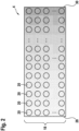
- the Figure 2 shows a schematic representation of a detector 4 according to a second embodiment.
- the detector 4 here has detector pixels 20 which have a different sensitivity.
- the sensitivity is high on a left side 28 of the detector surface 18, since the received rays 11 from objects 14 that are further away from the device 1 impinge here.
- the sensitivity of the detector pixels 20 is set linearly from a high sensitivity on the left side 28 to a low sensitivity on the right side 30.
- the sensitivity curve can alternatively be quadratic or exponential.
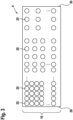
- FIG 3 is a schematic representation of a detector 4 according to a third embodiment.
- the sensitivity of the detector pixels 20 or the areas on the detector surface 18 is set via a detector pixel density. This means that more detector pixels 20 are available for detecting a long-distance area and fewer detector pixels 20 on the detector surface 18 are used for a short-range area.
Landscapes
- Engineering & Computer Science (AREA)
- Physics & Mathematics (AREA)
- Computer Networks & Wireless Communication (AREA)
- General Physics & Mathematics (AREA)
- Radar, Positioning & Navigation (AREA)
- Remote Sensing (AREA)
- Electromagnetism (AREA)
- Optical Radar Systems And Details Thereof (AREA)
- Measurement Of Optical Distance (AREA)
Description
- Die Erfindung betrifft eine LIDAR-Vorrichtung sowie ein Verfahren zum Abtasten eines Abtastwinkels und zum Auswerten eines ausgewählten Detektorbereiches.
- Bei LIDAR (Light detection and ranging) - Vorrichtungen wird ein Abstand zwischen der LIDAR-Vorrichtung und einem Objekt ermittelt. Hierzu wird ein Lichtpuls bzw. -strahl erzeugt und entlang eines Abtastwinkels emittiert. Befindet sich innerhalb des Abtastwinkels ein Objekt, so wird der Strahl reflektiert und kann von einem Detektor der LIDAR-Vorrichtung detektiert werden. Die Flugzeit des Strahls von dem Zeitpunkt der Erzeugung bis zum Zeitpunkt der Detektion kann gemessen und basierend auf der Lichtgeschwindigkeit des Strahls in eine Entfernung umgerechnet werden. Dieses Verfahren ist auch als "Time-of-Flight"-Verfahren bekannt. Detektoren in LIDAR-Vorrichtungen bestehen üblicherweise aus zeilenförmigen oder flächigen Matrizen bzw. Arrays aus einer Vielzahl an Detektorpixeln. In biaxialen LIDAR-Vorrichtungen befindet sich Sender und Empfänger auf getrennten optischen Achsen. Der erzeugte Lichtstrahl kann mithilfe eines Spiegels oder eines rotierenden Aufbaus innerhalb eines Gesichtsfeldes abgelenkt werden. Hierdurch kann ein Raumwinkel abgetastet werden. Unter regulären Betriebsbedingungen einer LIDAR-Vorrichtung trifft ein empfangener Strahl auf unterschiedliche Bereiche des Detektors. Ein Detektor wird somit nicht vollständig ausgeleuchtet, sondern grundsätzlich stellenweise. Bei gängigen LIDAR-Vorrichtungen wird zur Verarbeitung des empfangenen Strahls stets die gesamte Fläche des Detektors ausgewertet, da der belichtete Bereich auf dem Detektor und damit die Position des empfangenen Strahls unbekannt sind. Alternativ kann ein Bereich auf dem Detektor für die weitere Auswertung durch mehrere Messungen iterativ eingegrenzt werden. Hierdurch entsteht eine große Datenmenge, die in einem höheren Rechenaufwand bzw. einer langsameren Auswertung von Detektordaten resultieren kann.
-
US 2016/0123764 A1 beschreibt eine LIDAR-Vorrichtung, welche basierend auf zwei unterschiedlichen Messprinzipien betrieben wird. Für die Detektion von Objekten im Fernfeld wird das Time-of-Flight Messprinzip eingesetzt, bei welchem basierend auf einer Flugdauer der erzeugten Strahlen eine Entfernung des Objekts ermittelt wird. Der zweite Betriebsmodus wird im Nahfeld aktiviert und ermöglicht eine Abstandsmessung basierend auf dem Messprinzip der Triangulation. -
WO 2011/029651 A1 offenbart einen biaxialen optischen Flugzeit-Entfernungssensor mit einer Vielzahl von lichtempfindlichen Detektorelementen, deren Größe und Gruppierung zu Pixeln von der zu messenden Entfernung und damit von der Position auf der Detektionsfläche abhängt. So kann die effektive Detektionsfläche bei allen Entfernungen an die Größe des Empfangslichtflecks angepasst und die Entfernungsbestimmung auf die entsprechenden Signale beschränkt werden. Weiterer Stand der Technik ist ausDE 10 2015 205 826 A1 bekannt. - Die der Erfindung zugrunde liegende Aufgabe kann darin gesehen werden, ein Verfahren und eine LIDAR-Vorrichtung vorzuschlagen, die einen Detektor mit einem verbesserten Dynamikumfang und einer reduzierten Datenmenge bei einer Auswertung von detektierten Strahlen aufweist.
- Diese Aufgabe wird mittels des jeweiligen Gegenstands der unabhängigen Ansprüche gelöst. Vorteilhafte Ausgestaltungen der Erfindung sind Gegenstand von jeweils abhängigen Unteransprüchen.
- Nach einem Aspekt der Erfindung wird ein Verfahren zum Abtasten eines Abtastwinkels und zum Auswerten eines Detektors bereitgestellt. Bei dem Verfahren wird mindestens ein Strahl durch eine Strahlenquelle zum Abtasten des Abtastwinkels erzeugt. Mindestens ein an einem Objekt reflektierter Strahl wird durch eine Empfangsoptik empfangen und auf eine Detektorfläche des Detektors gelenkt und eine Flugdauer des mindestens einen reflektierten Strahls ermittelt. Der mindestens eine empfangene Strahl wird anschließend ausgewertet, wobei mindestens ein Bereich der Detektorfläche zum Auswerten des mindestens einen empfangenen Strahls abhängig von der Flugdauer des mindestens einen empfangenen Strahls ausgewählt wird.
- Abhängig von der Distanz des Objektes bzw. Zielobjekts zum Detektor trifft der empfangene Strahl an unterschiedlichen Stellen der Detektorfläche des Detektors auf. Der auf die Detektorfläche aufgetroffene empfangene Strahl stellt hierbei je nach Form des Strahls einen Messpunkt oder eine Messfläche dar. Durch geometrische Zusammenhänge zwischen dem Strahlenerzeuger, dem Detektor und einem Objekt, an dem mindestens ein erzeugter Strahl reflektiert werden, kann mit Hilfe der Flugzeit des erzeugten Strahls vom Zeitpunkt der Erzeugung bis zum Zeitpunkt der Detektion der Ort bzw. Bereich bestimmt werden, an dem der reflektierte Strahl auf der Detektorfläche auftreffen kann. Dies ist insbesondere durch den konstanten und bekannten Abstand zwischen dem Strahlenerzeuger und dem Detektor möglich, weil sich hierdurch der Einfallswinkel, unter dem ein reflektierter Strahl über eine Empfangsoptik oder direkt auf die Detektorfläche fällt ändert. Mit variierendem Einfallswinkel des reflektierten Strahls entsteht eine Abweichung des Bereiches, auf den der reflektierte Strahl trifft. Diese Abweichung ist direkt von der Flugzeit bzw. der Entfernung des Objektes von dem Detektor abhängig. Es kann somit durch das Ermitteln der Flugzeit des erzeugten Strahls eine Vorhersage über den Bereich auf der Detektorfläche getroffen werden, auf dem der reflektierte Strahl auftreffen wird. Hierdurch ist es nicht nötig die gesamte Detektorfläche für die weitere Auswertung des reflektierten Strahls auszuwerten. Vielmehr kann durch das Verfahren ein Bereich auf der Detektorfläche ausgewählt werden, der vorzugsweise kleiner als die Detektorfläche ist. Da nicht mehr die gesamte Detektorfläche zum Auswerten des Strahls verwendet wird, kann die Menge an Messwerten reduziert und die Auswertung bzw. Verarbeitung des detektierten Strahls beschleunigt werden. Im Falle einer parallelen Auswertung mehrerer detektierter reflektierter Strahlen kann die Anzahl an auszuwertenden Detektorpixeln und damit der Schaltungsaufwand reduziert werden. Im Falle einer sequenziellen oder seriellen Auswertung kann die Auswertung beschleunigt werden.
- Der mindestens eine Bereich der Detektorfläche wird abhängig von der Lichtgeschwindigkeit, einer Brennweite der Empfangsoptik und einem Abstand zwischen der Strahlenquelle und dem Detektor gewählt. In der Praxis ist die Entfernung zwischen dem Strahlenerzeuger und dem Objekt im Vergleich zur Distanz zwischen dem Strahlenerzeuger und dem Detektor größer, was in einem kleinen Einfallswinkel des reflektierten Strahls resultiert. Der Bereich auf der Detektorfläche, auf den der reflektierte Strahl auftrifft, verschiebt sich mit kleiner werdendem Abstand des Objektes zur Strahlenquelle von einem initialen Bereich. Diese kontinuierliche Verschiebung bzw. Abweichung kann durch einen Quotienten aus einem Produkt aus einer Brennweite der Empfangsoptik und dem Abstand zwischen dem Detektor und der Strahlenquelle und dem Abstand des Objektes zur Strahlenquelle berechnet werden. Hier kann der Abstand zwischen dem Objekt und dem Strahlenerzeuger alternativ als ein Produkt zwischen der Lichtgeschwindigkeit und der Flugdauer des erzeugten Strahls formuliert werden.
- Gemäß einem Ausführungsbeispiel wird abhängig von der Flugdauer des mindestens einen empfangenen Strahls der mindestens eine ausgewählte Bereich entlang der Detektorfläche in mindestens einer Dimension verschoben. Somit können nach dem Erzeugen des Strahls an der Strahlenquelle, die Bereiche auf der Detektorfläche als Funktion der Flugdauer von einer definierten Seite der Detektorfläche oder einem Detektorrand zu einer gegenüberliegenden Seite der Detektorfläche aktiviert werden um den reflektierten Strahl detektieren zu können. Der Bereich auf der Detektorfläche kann hierbei vorzugsweise eine Spalte auf dem Detektor sein. Hierdurch kann ein Schaltungsaufwand des Detektors reduziert werden. Der Detektor wird vorzugsweise lediglich im ausgewählten bzw. berechneten Bereich aktiviert. Außerhalb des gewählten Bereiches bleibt der Detektor deaktiviert. Vorzugsweise wird der aktivierte und zum Detektieren des reflektierten Strahls bereite Bereich in mindestens einer Dimension entlang der Detektorfläche verschoben.
- Nach einem weiteren Ausführungsbeispiel des Verfahrens wird eine Empfindlichkeit der Detektorpixel des Detektors abhängig von der Flugdauer des mindestens einen empfangenen Strahls gewählt. Basierend auf der Erkenntnis, dass der reflektierte Strahl bei einer geringen Entfernung des Objektes von der Strahlenquelle zu einer bestimmten Seite der Detektorfläche tendiert und bei einer großen Entfernung zu einer gegenüberliegenden Seite der Detektorfläche, ist es vorteilhaft, wenn die Detektorfläche eine variable Empfindlichkeit aufweist. Der Bereich der Detektorfläche, auf den die reflektierten Strahlen aus einer größeren Entfernung auftreffen, kann empfindlicher ausgeführt sein, da in einem Fernbereich die Intensität des reflektierten Strahls nachlässt. Der Bereich der Detektorfläche, auf den die reflektierten Strahlen aus einer geringen Entfernung des Objektes von der Strahlenquelle auftreffen, kann hingegen aufgrund der höheren Intensität des in einem Nahbereich reflektierten Strahls weniger sensitiv ausgeführt sein, um ein Übersättigen des Detektors zu vermeiden. Hierdurch kann insbesondere der Dynamikumfang des Detektors erhöht werden, sodass der Detektor sowohl bei weit entfernten Objekten als auch bei nahen Objekten stets optimale Detektionscharakteristik aufweist.
- Gemäß einem weiteren Ausführungsbeispiel wird die Fläche des zum Auswerten des empfangenen Strahls gewählten Bereiches der Detektorfläche abhängig von Störreflexen vergrößert oder verkleinert. Hierdurch kann die Fläche des Bereiches derart eingegrenzt oder angepasst werden, dass Störreflexe auf deaktivierte Bereiche der Detektorfläche treffen. Hierdurch können Fehldetektionen, die durch Umgebungslicht verursacht werden, verhindert werden.
- Nach einem weiteren Aspekt der Erfindung wird eine LIDAR-Vorrichtung zum Durchführen des Verfahrens zum Abtasten eines Abtastwinkels und zum Auswerten eines Detektors gemäß dem vorherigen Aspekt der Erfindung bereitgestellt. Die LIDAR-Vorrichtung weist mindestens eine Strahlenquelle zum Erzeugen mindestens eines Strahls und eine Einheit zum Abstrahlen des erzeugten Strahls in einen Abtastwinkel auf. Des Weiteren weist die LIDAR-Vorrichtung eine Empfangsoptik zum Empfangen von mindestens einem an einem Objekt reflektierten Strahl und zum Ablenken des empfangenen Strahls auf eine Detektorfläche eines Detektors auf, wobei abhängig von einer Flugdauer des mindestens einen empfangenen Strahls ein Bereich der Detektorfläche zum Auswerten des mindestens einen empfangenen Strahls auswählbar ist.
- Bei biaxialen LIDAR-Vorrichtungen wird ein reflektierter Strahl je nach Entfernung des Objektes bzw. Zielobjekts auf variierenden Stellen der Detektorfläche des Detektors abgebildet. Die Position des Messpunktes auf der Detektorfläche wird kontinuierlich in eine Richtung verschoben, wenn sich die Distanz zwischen Zielobjekt und der LIDAR-Vorrichtung kontinuierlich verändert. Befindet sich die Strahlenquelle beispielsweise links vom Detektor so verschiebt sich die Position des empfangenen Strahls auf der Detektorfläche von rechts nach links, wenn sich das Zielobjekt von dem Detektor entfernt und von links nach rechts wenn diese Distanz verringert wird. Diese Position des auf der Detektorfläche empfangenen Strahls kann basierend auf der Flugdauer des empfangenen Strahls durch Berechnung vorhergesagt werden. Durch die genaue Kenntnis des Bereiches auf der Detektorfläche des Detektors, auf den der empfangene Strahl auftrifft, muss nicht mehr die gesamte Detektorfläche für eine Auswertung des empfangenen Strahls verwendet werden, sondern ein flächig begrenzter Teilbereich der Detektorfläche. Hierdurch kann die Menge an Messwerten, die der Detektor erzeugt bzw. die zum weiteren Auswerten verwendet werden, reduziert werden.
- Nach einem Ausführungsbeispiel der LI DAR-Vorrichtung weist die Detektorfläche mindestens zwei über die Detektorfläche verteilte Detektorpixel auf. Vorzugsweise besteht die Detektorfläche des Detektors aus mehreren Detektorpixeln, die über die Detektorfläche regelmäßig oder unregelmäßig verteilt sind. Detektorpixel können beispielsweise Dioden oder Pixel von beispielsweise CCD oder CMOS Sensoren und dergleichen sein.
- Gemäß einem weiteren Ausführungsbeispiel weist der für die Auswertung des empfangenen Strahls gewählte Bereich der Detektorfläche mindestens einen Detektorpixel auf. Hierdurch wird verhindert, dass ein Bereich gewählt wird, der physikalisch einen empfangenen Strahl nicht mehr erfassen kann. Es können somit Messdaten mindestens eines Detektorpixels für weitere Auswertung des empfangenen Strahls verwendet werden.
- Gemäß einem weiteren Ausführungsbeispiel der LIDAR-Vorrichtung ist eine Empfindlichkeit der Detektorpixel entlang des Detektors variabel ausgeführt. Bei einem Objekt, das sich weit von der Strahlenquelle befindet, weisen die reflektierten Strahlen eine geringere Intensität auf, wenn sie empfangen werden als reflektierte Strahlen, die an nahen Objekten reflektiert werden. Somit können die Detektorpixel eine variable Empfindlichkeitsverteilung über die Detektorfläche hinweg aufweisen. Insbesondere Bereiche der Detektorfläche, die einen Fernbereich abdecken, können eine höhere Empfindlichkeit aufweisen und die Bereiche der Detektorfläche, die einen Nahbereich detektieren, können weniger empfindlich ausgeführt sein. Hierdurch können auch weit entfernte Objekte eindeutig detektiert werden und gleichzeitig ein Überbelichten bzw. ein Erreichen einer Sättigungsgrenze der Detektorpixel des Detektors bei nahen Objekten unterbunden werden. Durch die variable Empfindlichkeitsverteilung der Detektorpixel kann ein Dynamikumfang bzw. ein Arbeitsbereich des Detektors erhöht werden.
- Gemäß einem weiteren bevorzugten Ausführungsbeispiel ist die Empfindlichkeit der Detektorpixel entlang des Detektors an die Flugdauer des mindestens einen empfangenen Strahls anpassbar. Hierbei kann die Lichtsensitivität bzw. Empfindlichkeit der einzelnen Detektorpixel auf der Detektorfläche angepasst werden. Da die Strahlenquelle und der Detektor immer im gleichen Abstand und Winkel zueinander angeordnet sind, wird mindestens ein Messsignal von Objekten im Fern- bzw. Nahbereich immer in gleichen Bereichen auf der Detektorfläche erzeugt. Das bedeutet Detektorbereiche, die reflektierte Strahlen von Objekten im Fernbereich detektieren, können lichtsensitiver ausgeführt sein als in Bereichen, die reflektierte Strahlen von Objekten im Nahbereich detektieren. Dadurch kann eine Sättigungsgrenze erhöht bzw. der lineare Arbeitsbereich des Detektors erweitert werden. Die variable Empfindlichkeit kann beispielsweise über verschiedene Dioden-Typen, verschiedene Arbeitspunkte der Detektorpixel oder durch verschiedene Füllfaktoren erreicht werden. Füllfaktoren entsprechen hierbei dem Verhältnis der fotoaktiven Fläche zur gesamten Detektorfläche. Beispielsweise kann die Empfindlichkeit der Detektorfläche proportional zum Quadrat des Abstands des Objektes von der Strahlenquelle oder linear ausgeführt sein.
- Nach einem weiteren Ausführungsbeispiel der LIDAR-Vorrichtung ist der Bereich des Detektors eine Spalte aus mindestens einem Detektorpixel. Hierdurch kann ein Bereich in Form einer Spalte, die eine gesamte Höhe der Detektorfläche einnimmt, ausgeführt sein. Somit kann der für die Auswertung ausgewählte Bereich abhängig von der Flugdauer des empfangenen Strahls in zumindest einer Dimension entlang der Detektorfläche verschoben werden. Hierdurch kann der Schaltungsaufwand für das Anpassen des gewählten Bereiches reduziert werden und die Auswahl der relevanten Messdaten technisch vereinfacht werden.
- Im Folgenden werden anhand von stark vereinfachten schematischen Darstellungen bevorzugte Ausführungsbeispiele der Erfindung näher erläutert. Hierbei zeigen:
- Fig. 1
- eine schematische Darstellung einer LIDAR-Vorrichtung gemäß einem ersten Ausführungsbeispiel,
- Fig. 2
- eine schematische Darstellung eines Detektors gemäß einem zweiten Ausführungsbeispiel und
- Fig. 3
- eine schematische Darstellung eines Detektors gemäß einem dritten Ausführungsbeispiel
- In den Figuren weisen dieselben konstruktiven Elemente jeweils dieselben Bezugsziffern auf.
-
Figur 1 zeigt eine schematische Darstellung einer LIDAR-Vorrichtung 1 gemäß einem ersten Ausführungsbeispiel. Die LIDAR-Vorrichtung 1 dient insbesondere zum Durchführen eines Verfahrens zum Abtasten eines Abtastwinkels 2 und zum Auswerten eines Detektors 4. Gemäß dem Ausführungsbeispiel weist die LIDAR-Vorrichtung 1 eine Strahlenquelle 6 auf, die ein Infrarot-Laser 6 ist. Die Strahlenquelle 6 kann gepulste oder kontinuierliche elektromagnetische Strahlen 7 bzw. Infrarotstrahlen 7 erzeugen. Die Strahlen 7 werden über eine Einheit 8 in den Abtastwinkel 2 abgestrahlt. Die Einheit 8 ist gemäß dem Ausführungsbeispiel eine Kollimationsoptik. Zusätzlich kann Einheit 8 einen schwenkbaren Spiegel, der al-ternativ ein statischer Spiegel sein kann, ein Filter, ein Prisma und dergleichen beinhalten. Die Einheit kann optional eine Austrittsrichtung des Strahls 7 verändern, sodass der Strahl 7 vorzugsweise den gesamten Abtastwinkel 2 belichtet. - Sofern ein Objekt 10, 12, 14 im Abtastwinkel 2 positioniert ist, wird der erzeugte Strahl 7 an dem Objekt 10, 12, 14 reflektiert. Der erzeugte Strahl 7 wird nach dem Auftreffen auf das Objekt 10, 12, 14 zu einem reflektierten Strahl 9. Der reflektierte Strahl 9 wird anschließend von einer Empfangsoptik 16 empfangen. Die Empfangsoptik 16 ist hier der Einfachheit halber als eine konvexe Linse 16 dargestellt. Die Empfangsoptik 16 kann ein optisches Linsensystem sein, welches auch beschichtete Linsen, Spiegel, Filter, diffraktive optische Elemente und dergleichen aufweist. Die reflektierten Strahlen 9 werden von der Empfangsoptik 16 empfangen und als empfangene Strahlen 11 auf den Detektor 4 gelenkt. Die Empfangsoptik 16 kann hierbei starr oder dynamisch bzw. analog zur Einheit 8 beweglich ausgeführt sein. Die reflektierten Strahlen 9 treffen hierbei unter einem Einfallswinkel ϕ auf die Empfangsoptik 16. Die Empfangsoptik 16 ist in einem definierten Abstand L zu der Strahlenquelle 6 angeordnet und weist eine Brennweite f auf. Die Detektorfläche 18 ist hier durch die Brennweite f von der Empfangsoptik 16 beabstandet. Der Übersicht halber wurde in der Figur keine Brechung oder Beugung der reflektierten Strahlen 9 durch die Empfangsoptik 16 dargestellt.
- Gemäß dem Ausführungsbeispiel ist von dem Detektor 4 eine Detektorfläche 18 dargestellt. Die Detektorfläche 18 weist eine Vielzahl an Detektorpixeln 20 auf und dient zum Detektieren von empfangenen Strahlen 11. Die Detektorpixel 20 sind hier beispielsweise Fotodioden. Alternativ können die Detektorpixel 20 auch die Pixel eines CCD oder CMOS Sensors sein. Hierbei sind alle Detektorpixel 20 auf der Detektorfläche 18 gleich ausgeführt und gleichmäßig über die Detektorfläche 18 verteilt. Die Detektorpixel 20 bilden vielmehr eine Matrix aus mehreren Zeilen und Spalten. Abhängig von der Entfernung D der Strahlenquelle 6 bzw. der Abstrahleinheit 8 von einem Objekt 10, 12, 14 weisen die reflektierten Strahlen 9 einen unterschiedlichen Einfallswinkel ϕ auf, unter dem die reflektierten Strahlen 9 auf die Empfangsoptik 16 bzw. auf den Detektor 4 auftreffen. Abhängig von der Entfernung D des Objektes 10, 12 ,14 treffen die empfangenen Strahlen 11 auf unterschiedliche Bereiche 22, 24, 26 der Detektorfläche 18 auf. Je näher ein Objekt 10, 12, 14 an der Strahlenquelle 6 positioniert ist, desto weiter von einer linken Seite 28 der Detektorfläche 18 wird der empfangene Strahl 11 auftreffen. Der Abstand ΔL von der linken Seite der Detektorfläche 18 kann somit anhand der folgenden Formel berechnet werden:

- Wobei der Abstand D durch die Flugdauer t des erzeugten Strahls 7 ausgehend von der Strahlenquelle 6 bzw. der Einheit 8 bis zum Auftreffen auf den Detektor 4 ausgedrückt werden kann:

- Je nach Art der Empfangsoptik 16 kann abweichend von dem Einfallswinkel ϕ der empfangene Strahl 11 gebeugt oder gebrochen sein, sodass ein entsprechender Faktor bei der Berechnung des Abstands ΔL berücksichtigt werden muss. Wenn der empfangene Strahl 11 auf die Detektorfläche 18 trifft, wird der empfangene Strahl 11 durch die Detektorpixel 20 mindestens ein elektronisches Signal in Form einer Spannung umgewandelt. Jedes Detektorpixel 20 erzeugt sein eigenes elektronisches Signal. Nach dem Auftreffen des empfangenen Strahls 11 auf die Detektorfläche 20 kann ohne umfangreiche Auswertung die Flugdauer t und damit auch der Abstand D des Objektes 10, 12, 14 bestimmt werden. Damit weitere Informationen wie beispielsweise Form des Strahls 11, Intensität des Strahls 11 und Reflektivität des Objektes 10, 12, 14 ermittelt werden können, ist eine weitere Auswertung notwendig. Da die Flugzeit bereits ermittelt wurde, kann ein Bereich 22, 24, 26 auf der Detektorfläche 20 für diese weitere Auswertung gewählt werden. Somit müssen nicht die Signale aller Detektorpixel 20 ausgewertet werden, sondern nur die elektronischen Signale der Detektorpixei 20, die unmittelbar den empfangenen Strahl 11 bzw. Strahlen 11 registriert haben. Vorteilhafterweise können auch benachbarte Detektorpixel 20 ebenfalls in den gewählten Bereich 22, 24, 26 einbezogen werden, um Toleranzen auszugleichen und um sicherzustellen, dass keine Informationen verloren gehen.
- Die
Figur 2 zeigt eine schematische Darstellung eines Detektors 4 gemäß einem zweiten Ausführungsbeispiel. Im Unterschied zum Detektor 4 gemäß dem ersten Ausführungsbeispiel, weist der Detektor 4 hier Detektorpixel 20 auf, die eine unterschiedliche Empfindlichkeit aufweisen. Hierbei ist die Empfindlichkeit auf einer linken Seite 28 der Detektorfläche 18 hoch, da hier die empfangenen Strahlen 11 von Objekten 14 auftreffen, die weiter von der Vorrichtung 1 entfernt sind. Auf einer rechten Seite 30 der Detektorfläche 18 sind die Detektorpixel 20 weniger sensitiv bzw. empfindlich, da hier die empfangenen Strahlen von Reflexen naher Objekte 10 auftreffen und somit die Intensität der empfangenen Strahlen 11 grundsätzlich hoch ist und eine Gefahr einer Übersättigung der Detektorpixel 20 in diesem Bereich besteht. Die Empfindlichkeit der Detektorpixel 20 ist hier linear von einer hohen Empfindlichkeit auf der linken Seite 28 zu einer niedrigen Empfindlichkeit auf der rechten Seite 30 eingestellt. Der Verlauf der Empfindlichkeit kann alternativ quadratisch oder exponentiell verlaufen. - In der
Figur 3 ist eine schematische Darstellung eines Detektors 4 gemäß einem dritten Ausführungsbeispiel dargestellt. Im Unterschied zum zweiten Ausführungsbeispiel wird hier die Empfindlichkeit der Detektorpixel 20 bzw. der Bereiche auf der Detektorfläche 18 über eine Detektorpixeldichte eingestellt. Das bedeutet, dass für das Detektieren eines Fernbereiches mehr Detektorpixel 20 zur Verfügung stehen und für einen Nahbereich weniger Detektorpixel 20 auf der Detektorfläche 18 genutzt werden.
Claims (10)
- Verfahren zum Abtasten eines Abtastwinkels und zum Auswerten eines Detektors (4) einer LiDAR-Vorrichtung, wobei- mindestens ein Strahl (7) durch eine Strahlenquelle (6) zum Abtasten des Abtastwinkels erzeugt wird,- mindestens ein an einem Objekt (10, 12, 14) reflektierter Strahl (9) durch eine Empfangsoptik (16) empfangen und auf eine Detektorfläche (18) des Detektors (4) gelenkt wird,- eine Flugdauer (t) des mindestens einen reflektierten Strahls (9) mit der LiDAR-Vorrichtung ermittelt wird,- der mindestens eine empfangene Strahl (11) zur Ermittlung weiterer Informationen des empfangenen Strahls (11), insbesondere Form des Strahls (11) oder Intensität des Strahls (11) oder Reflektivität des Objektes (10, 12, 14), ausgewertet wird,dadurch gekennzeichnet, dass mindestens ein Bereich (22, 24, 26) der Detektorfläche (18) zum Auswerten des mindestens einen empfangenen Strahls (11) zur Ermittlung der weiteren Informationen des empfangenen Strahls (11) abhängig von der ermittelten Flugdauer (t) des mindestens einen empfangenen Strahls (11) ausgewählt wird zur Reduzierung der Menge an Messwerten und Beschleunigung der Auswertung des empfangenen Strahls (11),wobei der mindestens eine Bereich (22, 24, 26) der Detektorfläche (18) abhängig von der Lichtgeschwindigkeit (c0), einer Brennweite (f) der Empfangsoptik (16) und einem Abstand (L) zwischen der Strahlenquelle (6) und der Empfangsoptik (16) gewählt wird.
- Verfahren nach Anspruch 1, wobei abhängig von der ermittelten Flugdauer (t) des mindestens einen empfangenen Strahls (11) der mindestens eine ausgewählte Bereich (22, 24, 26) entlang der Detektorfläche (18) in mindestens einer Dimension verschoben wird.
- Verfahren nach einem der Ansprüche 1 bis 2, wobei eine Empfindlichkeit der Detektorpixel (20) des Detektors (4) abhängig von der ermittelten Flugdauer (t) des mindestens einen empfangenen Strahls (11) gewählt wird.
- Verfahren nach einem der Ansprüche 1 bis 3, wobei die Fläche des Bereiches (22, 24, 26) der Detektorfläche (18) abhängig von Störreflexen vergrößert oder verkleinert wird.
- LIDAR-Vorrichtung (1) zum Durchführen des Verfahrens zum Abtasten eines Abtastwinkels und zum Auswerten eines Detektors (4) gemäß einem der vorhergehenden Ansprüche mit mindestens einer Strahlenquelle (6) zum Erzeugen mindestens eines Strahls (7), mit einer Einheit (8) zum Abstrahlen des erzeugten Strahls (7) in einen Abtastwinkel, mit einer Empfangsoptik (16) zum Empfangen von mindestens einem an einem Objekt (10, 12, 14) reflektierten Strahl (9) und zum Ablenken des empfangenen Strahls (11) auf eine Detektorfläche (18) eines Detektors (4) der LIDAR-Vorrichtung (1), die zum Ermitteln einer Flugdauer (t) des mindestens einen reflektierten Strahls (9) und zum Auswerten des mindestens einen durch die Empfangsoptik (16) empfangenen Strahls (11) zur Ermittlung weiterer Informationen des empfangenen Strahls (11), insbesondere Form des Strahls (11) oder Intensität des Strahls (11) oder Reflektivität des Objektes (10, 12, 14), eingerichtet ist,dadurch gekennzeichnet, dass abhängig von der ermittelten Flugdauer (t) des mindestens einen empfangenen Strahls (11) ein Bereich (22, 24, 26) der Detektorfläche (18) zum Auswerten des mindestens einen empfangenen Strahls (11) zur Ermittlung der weiteren Informationen des empfangenen Strahls (11) auswählbar ist zur Reduzierung der Menge an Messwerten und Beschleunigung der Auswertung des empfangenen Strahls (11),wobei der eine Bereich (22, 24, 26) der Detektorfläche (18) abhängig von der Lichtgeschwindigkeit (c0), einer Brennweite (f) der Empfangsoptik (16) und einem Abstand (L) zwischen der Strahlenquelle (6) und der Empfangsoptik (16) auswählbar ist.
- LIDAR-Vorrichtung nach Anspruch 5, wobei die Detektorfläche (18) mindestens zwei über die Detektorfläche (18) verteilte Detektorpixel (20) aufweist.
- LIDAR-Vorrichtung nach Anspruch 5 oder 6, wobei der Bereich (22, 24, 26) der Detektorfläche (18) mindestens einen Detektorpixel (20) aufweist.
- LIDAR-Vorrichtung nach einem der Ansprüche 5 bis 7, wobei eine Empfindlichkeit der Detektorpixel (20) entlang der Detektorfläche (18) variabel ausgeführt ist.
- LIDAR-Vorrichtung nach Anspruch 8, wobei die Empfindlichkeit der Detektorpixel (20) entlang des Detektors (4) an die ermittelte Flugdauer (t) des mindestens einer empfangenen Strahls (11) anpassbar ist.
- LIDAR-Vorrichtung nach einem der Ansprüche 5 bis 9, wobei der Bereich (22, 24, 26) des Detektors (4) eine Spalte aus mindestens einem Detektorpixel (20) ist.
Applications Claiming Priority (2)
| Application Number | Priority Date | Filing Date | Title |
|---|---|---|---|
| DE102017206026.3A DE102017206026A1 (de) | 2017-04-07 | 2017-04-07 | LIDAR-Vorrichtung und Verfahren zum Abtasten eines Abtastwinkels und zum Auswerten eines Detektors |
| PCT/EP2018/057927 WO2018184942A1 (de) | 2017-04-07 | 2018-03-28 | Lidar-vorrichtung und verfahren zum abtasten eines abtastwinkels und zum auswerten eines detektors |
Publications (2)
| Publication Number | Publication Date |
|---|---|
| EP3607348A1 EP3607348A1 (de) | 2020-02-12 |
| EP3607348B1 true EP3607348B1 (de) | 2024-10-16 |
Family
ID=61801980
Family Applications (1)
| Application Number | Title | Priority Date | Filing Date |
|---|---|---|---|
| EP18713935.7A Active EP3607348B1 (de) | 2017-04-07 | 2018-03-28 | Lidar-vorrichtung und verfahren zum abtasten eines abtastwinkels und zum auswerten eines detektors |
Country Status (4)
| Country | Link |
|---|---|
| EP (1) | EP3607348B1 (de) |
| CN (1) | CN110476080B (de) |
| DE (1) | DE102017206026A1 (de) |
| WO (1) | WO2018184942A1 (de) |
Families Citing this family (2)
| Publication number | Priority date | Publication date | Assignee | Title |
|---|---|---|---|---|
| DE102019203640A1 (de) * | 2019-03-18 | 2020-09-24 | Robert Bosch Gmbh | Lidar-System mit holografischer Abbildungsoptik |
| CN117043639B (zh) * | 2021-12-30 | 2025-07-15 | 深圳引望智能技术有限公司 | 一种控制方法、激光雷达及终端设备 |
Family Cites Families (13)
| Publication number | Priority date | Publication date | Assignee | Title |
|---|---|---|---|---|
| DE102006049905B4 (de) * | 2006-10-23 | 2010-07-15 | Pepperl + Fuchs Gmbh | Optoelektronischer Sensor und Verfahren zu dessen Betrieb |
| DE102009028578A1 (de) * | 2009-08-17 | 2011-02-24 | Robert Bosch Gmbh | Verfahren für die Umfelderfassung mit einer Lidarsensorik |
| DE102009029364A1 (de) * | 2009-09-11 | 2011-03-24 | Robert Bosch Gmbh | Messvorrichtung zur Messung einer Entfernung zwischen der Messvorrichtung und einem Zielobjekt mit Hilfe optischer Messstrahlung |
| CN102565808B (zh) * | 2010-12-17 | 2015-10-21 | 上海无线电设备研究所 | 一种稀疏阵列高速三维成像激光雷达的实现方法 |
| CN103975250B (zh) * | 2011-10-14 | 2016-12-28 | Iee国际电子工程股份公司 | 在图像平面中利用动态掩模的空间选择性探测 |
| KR102038533B1 (ko) * | 2012-06-14 | 2019-10-31 | 한국전자통신연구원 | 레이저 레이더 시스템 및 목표물 영상 획득 방법 |
| DE102014111950A1 (de) * | 2013-11-27 | 2015-05-28 | Valeo Schalter Und Sensoren Gmbh | Abstastende optoelektronische Detektionseinrichtung und Verfahren zum Betreiben einer solchen Detektionseinrichtung sowie Kraftfahrzeug mit einer solchen Detektionseinrichtung |
| DE102015205826B4 (de) * | 2014-04-04 | 2020-03-12 | pmdtechnologies ag | Entfernungsmesssystem mit Lichtlaufzeitpixelzeile |
| US9952323B2 (en) * | 2014-04-07 | 2018-04-24 | Samsung Electronics Co., Ltd. | High resolution, high frame rate, low power image sensor |
| DE102014211071A1 (de) * | 2014-06-11 | 2015-12-17 | Robert Bosch Gmbh | Fahrzeug-Lidar-System |
| KR102144539B1 (ko) * | 2014-11-05 | 2020-08-18 | 주식회사 히타치엘지 데이터 스토리지 코리아 | 거리 측정 장치 |
| DE102015223675B4 (de) * | 2014-12-01 | 2023-09-07 | pmdtechnologies ag | Lichtlaufzeitsensor für einen optischer Entfernungsmesser |
| CN106291510A (zh) * | 2016-10-28 | 2017-01-04 | 深圳市镭神智能系统有限公司 | 一种基于时间飞行法的激光雷达光学系统 |
-
2017
- 2017-04-07 DE DE102017206026.3A patent/DE102017206026A1/de active Pending
-
2018
- 2018-03-28 CN CN201880023293.1A patent/CN110476080B/zh active Active
- 2018-03-28 WO PCT/EP2018/057927 patent/WO2018184942A1/de not_active Ceased
- 2018-03-28 EP EP18713935.7A patent/EP3607348B1/de active Active
Also Published As
| Publication number | Publication date |
|---|---|
| EP3607348A1 (de) | 2020-02-12 |
| DE102017206026A1 (de) | 2018-10-11 |
| WO2018184942A1 (de) | 2018-10-11 |
| CN110476080B (zh) | 2023-12-26 |
| CN110476080A (zh) | 2019-11-19 |
Similar Documents
| Publication | Publication Date | Title |
|---|---|---|
| EP1821120B1 (de) | Optoelektronische Vorrichtung und Verfahren zu deren Betrieb | |
| EP3279685B2 (de) | Optoelektronischer sensor und verfahren zur erfassung eines objekts | |
| DE3915627C2 (de) | ||
| EP2558883B1 (de) | Entfernungsmessgerät mit homogenisierender messauswertung | |
| DE60124647T2 (de) | Vorrichtung und Verfahren zur Abstandsmessung | |
| EP2486370B1 (de) | Optisches entfernungsmessgerät mit kalibrierungseinrichtung | |
| EP2475957B2 (de) | Optischer entfernungsmesser | |
| EP1321777A3 (de) | Verfahren zur Aufnahme eines Objektraumes | |
| EP2711667A1 (de) | Vorrichtung zur Entfernungsmessung | |
| DE102004037137A1 (de) | Verfahren und Vorrichtung zur Entfernungsmessung | |
| EP3336576B1 (de) | Verfahren zur erfassung einer 3d-szene mittels eines lidar-systems und lidar-system hierzu | |
| DE4211875A1 (de) | Optischer Abstandssensor | |
| DE102015217912A1 (de) | Verfahren zur Laufzeitkalibrierung eines Lidarsensors | |
| EP3168642A1 (de) | Optoelektronischer sensor und verfahren zur erfassung eines objekts | |
| DE102014117705B3 (de) | Abstandsmessvorrichtung und Verfahren zum Bestimmen eines Abstands | |
| EP2159603B1 (de) | Objektfeststellungsverfahren und Objektfeststellungssensor | |
| EP3933442A1 (de) | Sensor zum dreidimensionalen optischen vermessen eines objekts | |
| WO2018184942A1 (de) | Lidar-vorrichtung und verfahren zum abtasten eines abtastwinkels und zum auswerten eines detektors | |
| DE10340420A1 (de) | Optoelektronische Vorrichtung | |
| DE102019134701A1 (de) | Optoelektronischer Sensor und Verfahren zur Erfassung eines Objekts | |
| EP2306145B1 (de) | Optischer Sensor | |
| WO2018086786A1 (de) | Partikelsensor mit wenigstens zwei laser-doppler-sensoren | |
| DE3789901T2 (de) | Entfernungsmessung mit hilfe von diffraktion. | |
| DE102018111218B4 (de) | Verfahren und optoelektronischer Sensor zum Messen einer Entfernung von Objekten | |
| DE3901040C1 (de) |
Legal Events
| Date | Code | Title | Description |
|---|---|---|---|
| STAA | Information on the status of an ep patent application or granted ep patent |
Free format text: STATUS: UNKNOWN |
|
| STAA | Information on the status of an ep patent application or granted ep patent |
Free format text: STATUS: THE INTERNATIONAL PUBLICATION HAS BEEN MADE |
|
| PUAI | Public reference made under article 153(3) epc to a published international application that has entered the european phase |
Free format text: ORIGINAL CODE: 0009012 |
|
| STAA | Information on the status of an ep patent application or granted ep patent |
Free format text: STATUS: REQUEST FOR EXAMINATION WAS MADE |
|
| 17P | Request for examination filed |
Effective date: 20191107 |
|
| AK | Designated contracting states |
Kind code of ref document: A1 Designated state(s): AL AT BE BG CH CY CZ DE DK EE ES FI FR GB GR HR HU IE IS IT LI LT LU LV MC MK MT NL NO PL PT RO RS SE SI SK SM TR |
|
| AX | Request for extension of the european patent |
Extension state: BA ME |
|
| RAP1 | Party data changed (applicant data changed or rights of an application transferred) |
Owner name: ROBERT BOSCH GMBH |
|
| DAV | Request for validation of the european patent (deleted) | ||
| DAX | Request for extension of the european patent (deleted) | ||
| STAA | Information on the status of an ep patent application or granted ep patent |
Free format text: STATUS: EXAMINATION IS IN PROGRESS |
|
| 17Q | First examination report despatched |
Effective date: 20211220 |
|
| GRAP | Despatch of communication of intention to grant a patent |
Free format text: ORIGINAL CODE: EPIDOSNIGR1 |
|
| STAA | Information on the status of an ep patent application or granted ep patent |
Free format text: STATUS: GRANT OF PATENT IS INTENDED |
|
| INTG | Intention to grant announced |
Effective date: 20240806 |
|
| RIC1 | Information provided on ipc code assigned before grant |
Ipc: G01S 7/497 20060101ALI20240730BHEP Ipc: G01S 7/4914 20200101ALI20240730BHEP Ipc: G01S 7/4863 20200101ALI20240730BHEP Ipc: G01S 17/08 20060101AFI20240730BHEP |
|
| GRAS | Grant fee paid |
Free format text: ORIGINAL CODE: EPIDOSNIGR3 |
|
| GRAA | (expected) grant |
Free format text: ORIGINAL CODE: 0009210 |
|
| STAA | Information on the status of an ep patent application or granted ep patent |
Free format text: STATUS: THE PATENT HAS BEEN GRANTED |
|
| AK | Designated contracting states |
Kind code of ref document: B1 Designated state(s): AL AT BE BG CH CY CZ DE DK EE ES FI FR GB GR HR HU IE IS IT LI LT LU LV MC MK MT NL NO PL PT RO RS SE SI SK SM TR |
|
| REG | Reference to a national code |
Ref country code: GB Ref legal event code: FG4D Free format text: NOT ENGLISH |
|
| REG | Reference to a national code |
Ref country code: CH Ref legal event code: EP |
|
| REG | Reference to a national code |
Ref country code: IE Ref legal event code: FG4D Free format text: LANGUAGE OF EP DOCUMENT: GERMAN |
|
| REG | Reference to a national code |
Ref country code: DE Ref legal event code: R096 Ref document number: 502018015232 Country of ref document: DE |
|
| REG | Reference to a national code |
Ref country code: LT Ref legal event code: MG9D |
|
| REG | Reference to a national code |
Ref country code: NL Ref legal event code: MP Effective date: 20241016 |
|
| PG25 | Lapsed in a contracting state [announced via postgrant information from national office to epo] |
Ref country code: NL Free format text: LAPSE BECAUSE OF FAILURE TO SUBMIT A TRANSLATION OF THE DESCRIPTION OR TO PAY THE FEE WITHIN THE PRESCRIBED TIME-LIMIT Effective date: 20241016 |
|
| PG25 | Lapsed in a contracting state [announced via postgrant information from national office to epo] |
Ref country code: NL Free format text: LAPSE BECAUSE OF FAILURE TO SUBMIT A TRANSLATION OF THE DESCRIPTION OR TO PAY THE FEE WITHIN THE PRESCRIBED TIME-LIMIT Effective date: 20241016 |
|
| PG25 | Lapsed in a contracting state [announced via postgrant information from national office to epo] |
Ref country code: HR Free format text: LAPSE BECAUSE OF FAILURE TO SUBMIT A TRANSLATION OF THE DESCRIPTION OR TO PAY THE FEE WITHIN THE PRESCRIBED TIME-LIMIT Effective date: 20241016 Ref country code: PT Free format text: LAPSE BECAUSE OF FAILURE TO SUBMIT A TRANSLATION OF THE DESCRIPTION OR TO PAY THE FEE WITHIN THE PRESCRIBED TIME-LIMIT Effective date: 20250217 Ref country code: IS Free format text: LAPSE BECAUSE OF FAILURE TO SUBMIT A TRANSLATION OF THE DESCRIPTION OR TO PAY THE FEE WITHIN THE PRESCRIBED TIME-LIMIT Effective date: 20250216 |
|
| PG25 | Lapsed in a contracting state [announced via postgrant information from national office to epo] |
Ref country code: FI Free format text: LAPSE BECAUSE OF FAILURE TO SUBMIT A TRANSLATION OF THE DESCRIPTION OR TO PAY THE FEE WITHIN THE PRESCRIBED TIME-LIMIT Effective date: 20241016 |
|
| PG25 | Lapsed in a contracting state [announced via postgrant information from national office to epo] |
Ref country code: BG Free format text: LAPSE BECAUSE OF FAILURE TO SUBMIT A TRANSLATION OF THE DESCRIPTION OR TO PAY THE FEE WITHIN THE PRESCRIBED TIME-LIMIT Effective date: 20241016 |
|
| PG25 | Lapsed in a contracting state [announced via postgrant information from national office to epo] |
Ref country code: ES Free format text: LAPSE BECAUSE OF FAILURE TO SUBMIT A TRANSLATION OF THE DESCRIPTION OR TO PAY THE FEE WITHIN THE PRESCRIBED TIME-LIMIT Effective date: 20241016 |
|
| PG25 | Lapsed in a contracting state [announced via postgrant information from national office to epo] |
Ref country code: NO Free format text: LAPSE BECAUSE OF FAILURE TO SUBMIT A TRANSLATION OF THE DESCRIPTION OR TO PAY THE FEE WITHIN THE PRESCRIBED TIME-LIMIT Effective date: 20250116 |
|
| PG25 | Lapsed in a contracting state [announced via postgrant information from national office to epo] |
Ref country code: LV Free format text: LAPSE BECAUSE OF FAILURE TO SUBMIT A TRANSLATION OF THE DESCRIPTION OR TO PAY THE FEE WITHIN THE PRESCRIBED TIME-LIMIT Effective date: 20241016 Ref country code: GR Free format text: LAPSE BECAUSE OF FAILURE TO SUBMIT A TRANSLATION OF THE DESCRIPTION OR TO PAY THE FEE WITHIN THE PRESCRIBED TIME-LIMIT Effective date: 20250117 |
|
| PG25 | Lapsed in a contracting state [announced via postgrant information from national office to epo] |
Ref country code: PL Free format text: LAPSE BECAUSE OF FAILURE TO SUBMIT A TRANSLATION OF THE DESCRIPTION OR TO PAY THE FEE WITHIN THE PRESCRIBED TIME-LIMIT Effective date: 20241016 |
|
| PG25 | Lapsed in a contracting state [announced via postgrant information from national office to epo] |
Ref country code: RS Free format text: LAPSE BECAUSE OF FAILURE TO SUBMIT A TRANSLATION OF THE DESCRIPTION OR TO PAY THE FEE WITHIN THE PRESCRIBED TIME-LIMIT Effective date: 20250116 |
|
| PG25 | Lapsed in a contracting state [announced via postgrant information from national office to epo] |
Ref country code: SM Free format text: LAPSE BECAUSE OF FAILURE TO SUBMIT A TRANSLATION OF THE DESCRIPTION OR TO PAY THE FEE WITHIN THE PRESCRIBED TIME-LIMIT Effective date: 20241016 |
|
| PGFP | Annual fee paid to national office [announced via postgrant information from national office to epo] |
Ref country code: DE Payment date: 20250522 Year of fee payment: 8 |
|
| PG25 | Lapsed in a contracting state [announced via postgrant information from national office to epo] |
Ref country code: DK Free format text: LAPSE BECAUSE OF FAILURE TO SUBMIT A TRANSLATION OF THE DESCRIPTION OR TO PAY THE FEE WITHIN THE PRESCRIBED TIME-LIMIT Effective date: 20241016 |
|
| REG | Reference to a national code |
Ref country code: DE Ref legal event code: R097 Ref document number: 502018015232 Country of ref document: DE |
|
| PG25 | Lapsed in a contracting state [announced via postgrant information from national office to epo] |
Ref country code: EE Free format text: LAPSE BECAUSE OF FAILURE TO SUBMIT A TRANSLATION OF THE DESCRIPTION OR TO PAY THE FEE WITHIN THE PRESCRIBED TIME-LIMIT Effective date: 20241016 |
|
| PG25 | Lapsed in a contracting state [announced via postgrant information from national office to epo] |
Ref country code: RO Free format text: LAPSE BECAUSE OF FAILURE TO SUBMIT A TRANSLATION OF THE DESCRIPTION OR TO PAY THE FEE WITHIN THE PRESCRIBED TIME-LIMIT Effective date: 20241016 |
|
| PG25 | Lapsed in a contracting state [announced via postgrant information from national office to epo] |
Ref country code: SK Free format text: LAPSE BECAUSE OF FAILURE TO SUBMIT A TRANSLATION OF THE DESCRIPTION OR TO PAY THE FEE WITHIN THE PRESCRIBED TIME-LIMIT Effective date: 20241016 |
|
| PG25 | Lapsed in a contracting state [announced via postgrant information from national office to epo] |
Ref country code: CZ Free format text: LAPSE BECAUSE OF FAILURE TO SUBMIT A TRANSLATION OF THE DESCRIPTION OR TO PAY THE FEE WITHIN THE PRESCRIBED TIME-LIMIT Effective date: 20241016 |
|
| PG25 | Lapsed in a contracting state [announced via postgrant information from national office to epo] |
Ref country code: IT Free format text: LAPSE BECAUSE OF FAILURE TO SUBMIT A TRANSLATION OF THE DESCRIPTION OR TO PAY THE FEE WITHIN THE PRESCRIBED TIME-LIMIT Effective date: 20241016 |
|
| PLBE | No opposition filed within time limit |
Free format text: ORIGINAL CODE: 0009261 |
|
| STAA | Information on the status of an ep patent application or granted ep patent |
Free format text: STATUS: NO OPPOSITION FILED WITHIN TIME LIMIT |
|
| PG25 | Lapsed in a contracting state [announced via postgrant information from national office to epo] |
Ref country code: SE Free format text: LAPSE BECAUSE OF FAILURE TO SUBMIT A TRANSLATION OF THE DESCRIPTION OR TO PAY THE FEE WITHIN THE PRESCRIBED TIME-LIMIT Effective date: 20241016 |
|
| 26N | No opposition filed |
Effective date: 20250717 |
|
| PG25 | Lapsed in a contracting state [announced via postgrant information from national office to epo] |
Ref country code: MC Free format text: LAPSE BECAUSE OF FAILURE TO SUBMIT A TRANSLATION OF THE DESCRIPTION OR TO PAY THE FEE WITHIN THE PRESCRIBED TIME-LIMIT Effective date: 20241016 |
|
| REG | Reference to a national code |
Ref country code: CH Ref legal event code: H13 Free format text: ST27 STATUS EVENT CODE: U-0-0-H10-H13 (AS PROVIDED BY THE NATIONAL OFFICE) Effective date: 20251023 |
|
| PG25 | Lapsed in a contracting state [announced via postgrant information from national office to epo] |
Ref country code: LU Free format text: LAPSE BECAUSE OF NON-PAYMENT OF DUE FEES Effective date: 20250328 |
|
| GBPC | Gb: european patent ceased through non-payment of renewal fee |
Effective date: 20250328 |
|
| REG | Reference to a national code |
Ref country code: BE Ref legal event code: MM Effective date: 20250331 |
|
| PG25 | Lapsed in a contracting state [announced via postgrant information from national office to epo] |
Ref country code: GB Free format text: LAPSE BECAUSE OF NON-PAYMENT OF DUE FEES Effective date: 20250328 |
|
| PG25 | Lapsed in a contracting state [announced via postgrant information from national office to epo] |
Ref country code: BE Free format text: LAPSE BECAUSE OF NON-PAYMENT OF DUE FEES Effective date: 20250331 |
|
| PG25 | Lapsed in a contracting state [announced via postgrant information from national office to epo] |
Ref country code: CH Free format text: LAPSE BECAUSE OF NON-PAYMENT OF DUE FEES Effective date: 20250331 |
|
| PG25 | Lapsed in a contracting state [announced via postgrant information from national office to epo] |
Ref country code: IE Free format text: LAPSE BECAUSE OF NON-PAYMENT OF DUE FEES Effective date: 20250328 |
|
| PGFP | Annual fee paid to national office [announced via postgrant information from national office to epo] |
Ref country code: FR Payment date: 20260324 Year of fee payment: 9 |