EP3606622B1 - Automatisches ventil - Google Patents
Automatisches ventil Download PDFInfo
- Publication number
- EP3606622B1 EP3606622B1 EP18730414.2A EP18730414A EP3606622B1 EP 3606622 B1 EP3606622 B1 EP 3606622B1 EP 18730414 A EP18730414 A EP 18730414A EP 3606622 B1 EP3606622 B1 EP 3606622B1
- Authority
- EP
- European Patent Office
- Prior art keywords
- valve
- fire suppression
- piston
- suppression agent
- source
- Prior art date
- Legal status (The legal status is an assumption and is not a legal conclusion. Google has not performed a legal analysis and makes no representation as to the accuracy of the status listed.)
- Active
Links
Images



Classifications
-
- A—HUMAN NECESSITIES
- A62—LIFE-SAVING; FIRE-FIGHTING
- A62C—FIRE-FIGHTING
- A62C35/00—Permanently-installed equipment
- A62C35/58—Pipe-line systems
- A62C35/68—Details, e.g. of pipes or valve systems
-
- A—HUMAN NECESSITIES
- A62—LIFE-SAVING; FIRE-FIGHTING
- A62C—FIRE-FIGHTING
- A62C37/00—Control of fire-fighting equipment
- A62C37/36—Control of fire-fighting equipment an actuating signal being generated by a sensor separate from an outlet device
-
- F—MECHANICAL ENGINEERING; LIGHTING; HEATING; WEAPONS; BLASTING
- F16—ENGINEERING ELEMENTS AND UNITS; GENERAL MEASURES FOR PRODUCING AND MAINTAINING EFFECTIVE FUNCTIONING OF MACHINES OR INSTALLATIONS; THERMAL INSULATION IN GENERAL
- F16K—VALVES; TAPS; COCKS; ACTUATING-FLOATS; DEVICES FOR VENTING OR AERATING
- F16K31/00—Actuating devices; Operating means; Releasing devices
- F16K31/12—Actuating devices; Operating means; Releasing devices actuated by fluid
- F16K31/122—Actuating devices; Operating means; Releasing devices actuated by fluid the fluid acting on a piston
- F16K31/1223—Actuating devices; Operating means; Releasing devices actuated by fluid the fluid acting on a piston one side of the piston being acted upon by the circulating fluid
Definitions
- the present invention relates to an automatic valve particularly, but not exclusively, for use in conjunction with a fire suppression system.
- Fire suppression systems can either be manually or automatically activated.
- An example of an automatic system is a sprinkler system that is activated in response to detection of heat.
- the system is defined by a network of water pipes suspended from the ceiling of a building interspersed by a plurality of sprinkler heads.
- Each sprinkler head has a plug which is designed to burst or melt in response to application of heat. In this way, the system is effective at dousing a localised fire by way of activation of one, or a few sprinkler heads, or a larger fire through activation of multiple sprinkler heads.
- Sprinkler systems typically use water as medium but water is not appropriate for fighting all types of fire. In the event of an electrical fire, application of water to the fire would potentially cause the fire to spread further. Furthermore, a sprinkler head is only activated following heating of the temperature sensitive plug by hot gases generated in the event of a fire. The hot gases would therefore have to be relatively localised in order to activate a sprinkler head thus potentially resulting in a delay between a fire taking hold and activation of the fire suppression system.
- An example of a larger system where use of water might not be desirable is a pneumatic system that utilises a run of heat sensitive tube in the vicinity of equipment to be protected.
- the tubing is connected to a cylinder containing a fire suppression agent.
- the system loses pressure and causes the cylinder to deliver a fire suppression agent to a plurality of valves that are not directly connected to the tubing.
- the pressure of the agent causes a cap to blow off each valve so that the fire suppression medium can be delivered to the source of the fire.
- Such systems are effective at fighting a fire in either a specific area or over a broader area but the response time can be diminished by the system first having to detect that pressure has been lost due to burst tubing before delivering a fire suppression agent through a separate tube or pipe network to the heat sensitive tubing.
- Some pneumatic systems also provide a manual actuator which causes pneumatic pressure in the system to drop when actuated.
- a manual actuator provides means for an operator to quickly deploy the fire suppression system in the event of a fire rather than waiting for the temperature sensitive tubing to burst.
- US3860073A discloses a discharge valve for each of a plurality of manifold connected containers for fire extinguishing fluid, the discharge valve including a main valve pressure seated by fluid in the container to which it is attached and openable by pressure in the valve outlet from the manifold. This action is achieved by use of a double faced two diameter piston integral with the main valve member.
- GB2439338A discloses a valve for controlling a high pressure circuit in dependence on the pressure in a low pressure reservoir has a valve member in the form of a stepped piston working in a stepped cylinder.
- the low pressure acts on the larger diameter piston step and the high pressure acts on the smaller piston step, with the pressure and the piston dimensions being such that the low pressure normally maintains the valve member in a position where the high pressure circuit is closed.
- GB2509074A discloses a self-contained transportable fire extinguishing unit comprising a reservoir of a fire extinguishing medium or extinguishant.
- the unit has a housing which supports the reservoir.
- WO2006/130363A2 discloses a vehicle having a tire fire suppression system including a vehicle body for transportation of occupants or cargo. A plurality of combustible tires is connected to the body. The present invention seeks to address the aforementioned problems.
- An aspect of the invention provides an automatic valve comprising a body configured to receive a piston axially therein, the piston being movable within the body between a first axial position in which the piston is configured to seal a valve opening when pneumatic pressure is applied to the piston and a second axial position in which the piston is configured to be withdrawn from the valve opening such that a fire suppression agent can enter the valve body through the valve opening.
- the present invention provides a means of automatically activating a fire suppression system in the event of a fire in the vicinity of one or more automatic valves.
- Pneumatic pressure is used to urge a piston in a downwards axial configuration in order to seal a valve opening during normal operation.
- the pneumatic pressure holding the piston down is removed and the piston is urged upwardly by pressurised fire suppression agent forcing its way through the valve opening and overcoming the pressure differential that is provided by the pneumatic pressure acting on the piston.
- This configuration provides a quick response time following detection of a fire and provides a reliable means of automatically deploying a fire suppression agent.
- the piston comprises a channel longitudinally therethrough and a check valve positioned within the channel such that fluid can enter the check valve in a first longitudinal direction but not in a second longitudinal direction.
- Provision of a check valve in a channel through the piston eliminates cross-contamination of medium between the discharge and detection lines of a fire suppression system as can occur in the prior art. Furthermore, the check valve minimises pressure loss of the fire suppression system caused by leakage of medium past the piston.
- Use of a check valve also enables a larger diameter channel through the piston to be used to facilitate efficient charging of the automatic valve than is possible in the prior art. For example, many prior art valves use a channel having an opening diameter of 0.5mm in communication with a 2mm diameter shaft, or less, to reduce pressure loss through the valve.
- the present embodiment of the invention can use a much greater diameter opening fitted with a check valve. Fluid can only pass through the check valve in a single direction into the 2mm diameter channel, or shaft. Such a configuration results in a calibrated leak rate of only 20 sccm.
- the body comprises a first part for receiving the piston therein and a second part, the second part comprising a connector for connecting the body to an air source.
- Manufacture of the automatic valve in two parts is advantageous in order to aid assembly of the valve in such a way that the piston can be axially restrained therein.
- first part of the body comprises a first threaded portion and the second part of the body comprises a second threaded portion co-operable with the first threaded portion.
- Connecting the first part of the body and the second part of the body via a threaded connection enables the body to be easily disassembled during servicing or replacement.
- first threaded portion defines a male thread and the second threaded portion defines a female thread.
- Such a configuration ensures that the thread is effectively an internal thread with no access to the environment. This is advantageous as many items of equipment are used in hostile environments which might see a range of temperatures and humidity or debris particles that could clog an external thread. Use of an internal thread reduces the possibility of damage to the threads.
- the first part of the body defines a cylindrical chamber.
- a cylindrical chamber is advantageous so as to provide a curved internal surface that cooperates with a lubricated o-ring around the piston. Avoidance of angled axial surfaces is desirable to aid axial movement of the piston relative to the body.
- the second part of the body defines an attachment interface co-operable with a tool.
- the first part of the body will be fastened to a pipe network and air source.
- the design of an automatic isolation valve according to embodiments of the invention is such that the second part of the body can be detached from the first part of the body to access the piston while the first part of the body remains in place. Provision of an attachment interface co-operable with a tool is thus desirable to facilitate removal and replacement of the second part of the body.
- the piston comprises first and second abutment surfaces engageable with the body to constrain axial movement of the piston.
- Movement of the piston requires limiting axially to ensure that it can only move as far as is necessary to perform its desired function, i.e. 13.3mm in the illustrated embodiments.
- the second part of the body further comprises a third abutment surface engageable with the first abutment surface of the piston when the piston is in the second axial position.
- Such a configuration ensures that the piston can only ever be a maximum pre-determined distance away from the mechanical isolation switch when pneumatic pressure is activated. This is important as the greater distance the piston has to travel towards the mechanical isolation switch the higher the risk of the valve failing. Limiting the distance that the piston is required to travel to within known tolerances negates this risk.
- the first part of the body further comprises a fourth abutment surface engageable with the second abutment surface of the piston when the piston is in the first axial position.
- Provision of the abutment surface between the first part of the body and the piston effectively provides a secure seat against which the piston is urged when pneumatic pressure is applied.
- the piston further comprises an annular recess between the first and second abutment surfaces, the annular recess configured to receive an annular seal.
- the annular recess provides a seat for an annular seal that provides one of three seals between the piston and the body to prevent leakage of air from the chamber defined by the body.
- the valve comprises a first seal received in the annular recess of the piston configured to provide a seal between the piston and the first part of the body, a second seal received by the shaft of the piston configured to provide a seal between the second abutment surface of the piston and the fourth abutment surface of the first part of the body and a third seal between the first part of the body and the second part of the body configured to provide a seal therebetween.
- the first and second seals provide seals between the piston and the body to prevent leakage of air and thus unplanned activation of the valve.
- the third seal provides a seal between the two parts of the body for the same purpose.
- Each potential leak path is sealed by at least a dual seal arrangement to reduce the risk of air leakage as far as is possible.
- a fire suppression system comprising one or more automatic valves, a temperature sensitive detection means for detecting the presence of a fire or abnormal heat, a pneumatic air source for maintaining each of the one or more automatic valves in a normal operating condition and a fire suppression agent source connected to each of the one or more automatic valves, wherein detection of a fire or abnormal heat by the temperature sensitive detection means automatically causes pneumatic pressure to the one or more automatic valves to be removed and removal of the pneumatic pressure enables fire suppression agent from the fire suppression agent source to enter the one or more automatic valves through the first valve opening and disperse from the one or more automatic valves through the second valve opening.
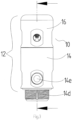
- the figures show various views of an automatic valve 10 according to embodiments of the invention.
- the automatic valve 10 is connected to a fire suppression system that comprises multiple automatic valves connected by burst tubing and pipework for delivering a fire suppression agent.
- the automatic valve 10 comprises a body 12 formed from a first part 14 and a second part 16.
- the first part of the body 12 defines a first end 14a and a second end 14b.
- the first end 14a is defined by an internal female thread 14c and is tapered to aid alignment of the second part 16 of the body 12 with the first part 14 of the body 12.
- the second end 14b defines an outer male thread 14d configured for mounting the automatic valve to a fire suppression system and first opening 14i configured for connecting pipework to the automatic valve 10.
- At least two further openings 14f, 14g are provided at the second end 14b of the first part 14 of the body 12 arranged perpendicularly to the first outlet 14i.
- the first part 14 of the body 12 defines a machined chamber 14h for receiving a piston 18.
- An annular projection 14g defines a seat against which the piston 18 abuts when the automatic valve 10 is in a normal operating condition, i,e. the piston 18 is urged downwardly by pneumatic pressure.
- the second part 16 of the body 12 comprises a male threaded portion 16a that is configured to screw into the internal female thread 14c of the first part 14 of the body 12 and a machined portion 16b configured for engagement with a tool to rotate the second part 16 of the body 12 relative to the first part 14 of the body 12.
- a seal 20 is provided on the threaded portion 16a to provide a seal between the threaded portion 16a and the internal female thread 14c.
- the machined portion 16b comprises diametrically opposed flat spots for engagement with a spanner.
- the second part 16 of the body 12 further comprises an axial air port 16c therethrough which is internally threaded to receive a connector (not shown) for connecting the second part 14 of the body 12 to an air source.
- the underside 16d of the threaded portion 16a of the second part 16 of the body 12 defines an abutment surface configured for abutment with a portion of the piston 18 as will be described further below.
- the piston 18 comprises a primary cylindrical shaft 18a and a secondary cylindrical shaft 18b separated by a machined flange 18c including a planar upper and lower face, each defining a respective abutment surface 18d, 18e, and an annular recess 18f configured to receive a seal 22 for providing a seal between the machined flange 18c and the first part 14 of the body 12.
- Certain embodiments of the inventions comprise a channel 18g provided longitudinally through the piston 18 to enable charging of the automatic valve 10.
- the channel 18g has a diameter of between 0.5mm to 2mm.
- Certain embodiments of the invention also comprise a check valve 28 positioned in the channel 18g, as shown in the figures.
- the channel 18g has an opening that has a greater diameter than the rest of the channel 18g and within which the check valve 28 is situated.
- the check valve 28, or non-return valve operates to only enable fluids (i.e. liquids or gases) to pass through the check valve 28 in one direction.
- the check valve 28 has both an inlet port 28a and an outlet port 28b which are operable automatically without any manual intervention. Fluid intended to pass through the check valve 28 is required to exceed a predetermined pressure, or cracking pressure, for the inlet port 28a and/or outlet port 28b to open.
- the fire suppression medium is injected through the check valve 28 into the channel 18g to fill the void 14h present when the piston 18 is positioned in its lowermost axial position with respect to the body 12. Once charged, any leakage of fire suppression medium through the piston 18 is negligible, i.e. around 20 sccm.
- the abutment surface 18d of the machined flange 18c of the piston 18 abuts the abutment surface 16d of the second part 16 of the body 12 when the piston is positioned in its uppermost axial positon with respect to the body 12.
- the abutment surface 18e of the machined flange 18c of the piston 18 abuts the uppermost surface of the annular projection 14g of the second part 14 of the body 12 when the piston 18 is in its lowermost axial position with respect to the body 12.
- a further seal 24 is provided on the primary shaft 18a of the piston 18 and provides a seal between the primary shaft 18a of the piston 18 and the first opening 14i of the second part 14 of the body 12.
- An o'ring 26 is provided on or around the secondary cylindrical shaft 18b of the piston 18. The o'ring 26 seals between the secondary cylindrical shaft 18b of the piston 18 and the axial air port 16c of the second part 16 of the body 12.
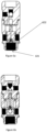
- Figures 6a and 6b exemplify a third embodiment of the invention wherein the valve opening (601) is of greater diameter than in previous embodiments of the invention.
- the ratio of the inner diameter of the valve opening (601) to the outer diameter of the valve opening is preferably 50:100 to 80:100, preferably 65:100 to 75:100, most preferably 70:100 to 75:100.
- Figures 6a and 6b also exemplify a further advantageous feature of a chamfer (602) inside of the valve opening (601) distal to a fire suppression agent source at an angle towards the axis of the valve of preferably 30-70, more preferably 40-65, most preferably 45-60 degrees.
- the chamfer directs the fire suppression medium towards openings 14e, 14f and 14i.
- the chamfer preferably has a depth of 1-3 mm, more preferably 1.5-2 mm.
- the surface roughness Ra of the chamfer may be 2-8 microns (RMS).
- the automatic valve 10 is connected to an air source (not shown) delivered by a heat sensitive plastic tube to the connector into the second part 16 of the body 12.
- an air source (not shown) delivered by a heat sensitive plastic tube to the connector into the second part 16 of the body 12.
- air source is activated, air is introduced through the axial air port 16c and urged against the abutment surface 18d and secondary shaft 18b of the piston 18 to drive the piston 18 downwards into its lowermost axial position with respect to the body 12.
- the piston 18 blocks the valve openings 14e, 14f, 14i of the first part 14 of the body 12.
- the piston 26 When the air source is deactivated for any reason, the piston 26 is no longer urged against the valve openings 14d, 14e, 14i and the pressure of the fire suppression agent within the system provides a greater pressure differential between the first 14 and second 16 parts of the body 12 such that the piston 18 is urged upwardly by the pressure of the fire suppression medium thus exposing the valve openings 14e, 14f, 14i and enabling fire suppression agent to flow through the valve 10.
Landscapes
- Engineering & Computer Science (AREA)
- General Engineering & Computer Science (AREA)
- Health & Medical Sciences (AREA)
- Public Health (AREA)
- Business, Economics & Management (AREA)
- Emergency Management (AREA)
- Mechanical Engineering (AREA)
- Fire-Extinguishing By Fire Departments, And Fire-Extinguishing Equipment And Control Thereof (AREA)
- Safety Valves (AREA)
Claims (16)
- Automatisches Ventil (10) und eine Quelle für ein Feuerlöschmittel, wobei das automatische Ventil einen Ventilkörper (12), einen Kolben (18) und eine erste Ventilöffnung umfasst, wobei der Körper einen ersten Teil zum Aufnehmen des Kolbens darin und einen zweiten Teil umfasst, wobei der zweite Teil einen Verbinder zum Verbinden des Körpers mit einer Luftquelle umfasst, die pneumatischen Druck bereitstellt, wobei der Körper dazu konfiguriert ist, den Kolben (18) axial darin aufzunehmen, wobei der Kolben innerhalb des Körpers zwischen einer ersten axialen Position, in der der Kolben dazu konfiguriert ist, die erste Ventilöffnung (14e, 14f, 14i) abzudichten, und einer zweiten axialen Position beweglich ist, wobei der Ventilkörper mit einer Quelle für ein Feuerlöschmittel verbunden ist, die ein Feuerlöschmittel bei einem Feuerlöschmitteldruck umfasst, und wobei der Kolben (18) innerhalb des Körpers in eine erste axiale Position beweglich ist, wenn der Feuerlöschmitteldruck geringer als der pneumatische Druck ist, und wobei der Kolben dazu konfiguriert ist, nur dann aus der ersten Ventilöffnung zurückgezogen zu werden, wenn der Feuerlöschmitteldruck größer als der pneumatische Druck ist, sodass das Feuerlöschmittel durch die erste Ventilöffnung (14i) in den Ventilkörper eintreten kann.
- Automatisches Ventil und eine Quelle für ein Feuerlöschmittel nach Anspruch 1, wobei der Kolben (18) einen in Längsrichtung durch diesen hindurch verlaufenden Kanal (18g) und ein Rückschlagventil (28) umfasst, das innerhalb des Kanals so positioniert ist, dass ein Fluid in einer ersten Längsrichtung in das Rückschlagventil eintreten kann, jedoch nicht in einer zweiten Längsrichtung.
- Automatisches Ventil und eine Quelle für ein Feuerlöschmittel nach Anspruch 2, wobei der Kanal (18g) einen Durchmesser von 2 mm oder mehr und eine Kanalöffnung mit einem Durchmesser von mehr als 2 mm aufweist, um das Rückschlagventil (28) aufzunehmen.
- Automatisches Ventil und eine Quelle für ein Feuerlöschmittel nach Anspruch 1, wobei der erste Teil (14) einen ersten Gewindeabschnitt (14c) umfasst und der zweite Teil (16) einen zweiten Gewindeabschnitt (16a) umfasst, der mit dem ersten Gewindeabschnitt zusammenwirken kann.
- Automatisches Ventil und eine Quelle für ein Feuerlöschmittel nach Anspruch 4, wobei der erste Gewindeabschnitt (14c) ein Außengewinde definiert und der zweite Gewindeabschnitt (16a) ein Innengewinde definiert.
- Automatisches Ventil und eine Quelle für ein Feuerlöschmittel nach Anspruch 1, wobei der erste Teil des Körpers (14) eine zylindrische Kammer (14h) definiert.
- Automatisches Ventil und eine Quelle für ein Feuerlöschmittel nach Anspruch 1, wobei der zweite Teil des Körpers (16) eine Befestigungsschnittstelle (16b) definiert, die mit einem Werkzeug zusammenwirken kann.
- Automatisches Ventil und eine Quelle für ein Feuerlöschmittel nach Anspruch 7, wobei der Kolben (18) eine erste und eine zweite Anschlagfläche (18d, 18e) umfasst, die mit dem Körper (12) in Eingriff gebracht werden können, um die axiale Bewegung des Kolbens einzuschränken.
- Automatisches Ventil und eine Quelle für ein Feuerlöschmittel nach Anspruch 8, wobei der zweite Teil des Körpers (16) ferner eine dritte Anschlagfläche (16d) umfasst, die mit der ersten Anschlagfläche des Kolbens (18d) in Eingriff gebracht werden kann, wenn sich der Kolben in der zweiten axialen Position befindet.
- Automatisches Ventil und eine Quelle für ein Feuerlöschmittel nach Anspruch 8, wobei der Kolben (18) ferner eine ringförmige Aussparung (18f) zwischen der ersten und der zweiten Anschlagfläche (18d, 18e)) umfasst, wobei die ringförmige Aussparung dazu konfiguriert ist, eine ringförmige Dichtung (22) aufzunehmen.
- Automatisches Ventil und eine Quelle für ein Feuerlöschmittel nach Anspruch 10, ferner umfassend eine erste Dichtung (22), die in der ringförmigen Aussparung des Kolbens (18f) aufgenommen ist und dazu konfiguriert ist, eine Abdichtung zwischen dem Kolben (18) und dem ersten Teil des Körpers (14) bereitzustellen, eine zweite Dichtung (24), die vom Schaft des Kolbens (18a) aufgenommen ist und dazu konfiguriert ist, eine Abdichtung zwischen der zweiten Anschlagfläche des Kolbens (18e) und einer vierten Anschlagfläche des ersten Teils des Körpers (14g) bereitzustellen, und eine dritte Dichtung (20) zwischen dem ersten Teil des Körpers (14) und dem zweiten Teil des Körpers (16), die dazu konfiguriert ist, eine Abdichtung dazwischen bereitzustellen.
- Automatisches Ventil und eine Quelle für ein Feuerlöschmittel nach Anspruch 1, wobei der Ventilkörper (12) einen ersten Luftanschluss (16c) umfasst, der axial damit ausgerichtet ist und für die Verbindung mit einer Luftquelle konfiguriert ist.
- Automatisches Ventil und eine Quelle für ein Feuerlöschmittel nach Anspruch 12, wobei der Ventilkörper ferner einen zweiten Luftanschluss umfasst, der senkrecht zum ersten Luftanschluss ausgerichtet ist und für die Verbindung mit einem weiteren automatischen Ventil konfiguriert ist.
- Automatisches Ventil und eine Quelle für ein Feuerlöschmittel nach Anspruch 1, wobei der erste Teil (14) die erste Ventilöffnung (601) umfasst, wobei die erste Ventilöffnung (601) einen Innen- und einen Außendurchmesser aufweist und wobei das Verhältnis des Innendurchmessers der ersten Ventilöffnung zum Außendurchmesser der ersten Ventilöffnung 50:100 bis 80:100 beträgt.
- Automatisches Ventil und eine Quelle für ein Feuerlöschmittel nach Anspruch 14, wobei die erste Ventilöffnung (601) ferner eine Fase (602) innerhalb der ersten Ventilöffnung distal zur Feuerlöschmittelquelle umfasst, und wobei die Fase einen Winkel von 30 bis 70 Grad zur Achse des Ventils hin einnimmt.
- Feuerlöschsystem, umfassend mindestens ein automatisches Ventil und eine Quelle für ein Feuerlöschmittel nach Anspruch 1, ein temperaturempfindliches Erkennungsmittel zum Erkennen des Vorhandenseins eines Feuers oder einer erhöhten Temperatur, eine pneumatische Luftquelle zum Aufrechterhalten jedes von dem einen oder den mehreren automatischen Ventilen in einem normalen Betriebszustand, wobei die Erkennung eines Feuers oder einer erhöhten Temperatur im Verhältnis zur Umgebungstemperatur durch das temperaturempfindliche Erkennungsmittel automatisch bewirkt, dass der pneumatische Druck zu dem einen oder den mehreren automatischen Ventilen entfernt wird, und das Entfernen des pneumatischen Drucks es dem Feuerlöschmittel aus der Feuerlöschmittelquelle ermöglicht, durch die erste Ventilöffnung (601) in das eine oder die mehreren automatischen Ventile einzutreten und sich durch die zweite Ventilöffnung (14d, 14e) aus dem einen oder den mehreren automatischen Ventilen zu verteilen.
Applications Claiming Priority (3)
| Application Number | Priority Date | Filing Date | Title |
|---|---|---|---|
| GBGB1705415.6A GB201705415D0 (en) | 2017-04-04 | 2017-04-04 | Automatic valve |
| GB1718605.7A GB2568276B8 (en) | 2017-11-10 | 2017-11-10 | Automatic valve |
| PCT/GB2018/050911 WO2018185484A1 (en) | 2017-04-04 | 2018-04-04 | Automatic valve |
Publications (2)
| Publication Number | Publication Date |
|---|---|
| EP3606622A1 EP3606622A1 (de) | 2020-02-12 |
| EP3606622B1 true EP3606622B1 (de) | 2024-09-04 |
Family
ID=62567685
Family Applications (1)
| Application Number | Title | Priority Date | Filing Date |
|---|---|---|---|
| EP18730414.2A Active EP3606622B1 (de) | 2017-04-04 | 2018-04-04 | Automatisches ventil |
Country Status (10)
| Country | Link |
|---|---|
| US (1) | US11547886B2 (de) |
| EP (1) | EP3606622B1 (de) |
| DK (1) | DK3606622T3 (de) |
| ES (1) | ES2987460T3 (de) |
| FI (1) | FI3606622T3 (de) |
| LT (1) | LT3606622T (de) |
| PL (1) | PL3606622T3 (de) |
| PT (1) | PT3606622T (de) |
| WO (1) | WO2018185484A1 (de) |
| ZA (1) | ZA202000328B (de) |
Families Citing this family (6)
| Publication number | Priority date | Publication date | Assignee | Title |
|---|---|---|---|---|
| GB2605657A (en) | 2021-04-08 | 2022-10-12 | Reacton Fire Suppression Ltd | Gas-operated valve |
| DK4319890T3 (da) | 2021-04-08 | 2025-02-24 | Reacton Fire Suppression Ltd | Gasdrevet ventil |
| USD1055977S1 (en) * | 2022-06-13 | 2024-12-31 | Reacton Fire Suppression Ltd | Fluid distribution manifold |
| US20240108926A1 (en) * | 2022-10-03 | 2024-04-04 | Jeremy Ryan Bradfield | Systems, methods, and apparatuses for implementing in-situ configurable diffusion characteristics of mass water flows |
| EP4574221A1 (de) | 2023-12-20 | 2025-06-25 | POWERTECH International GmbH | Automatisches ventil für brandbekämpfungs- und brandunterdrückungssysteme |
| CN121803695A (zh) | 2024-10-07 | 2026-04-07 | 动力科技国际有限公司 | 用于消防和灭火系统的自动阀门 |
Family Cites Families (13)
| Publication number | Priority date | Publication date | Assignee | Title |
|---|---|---|---|---|
| US3651823A (en) | 1970-04-29 | 1972-03-28 | James Leland Milsted Sr | Thermal sensing blow out preventer actuating device |
| US3744506A (en) | 1970-04-29 | 1973-07-10 | Cameron Iron Works Inc | Thermal sensing actuating device |
| US3860073A (en) | 1974-01-25 | 1975-01-14 | Norris Industries | Fire extinguisher discharge valve |
| FI113155B (fi) | 2002-01-17 | 2004-03-15 | Marioff Corp Oy | Venttiilielin |
| US7434629B2 (en) | 2005-05-31 | 2008-10-14 | Kidde Technologies Incorporated | Tire fire suppression and vehicle with same |
| GB2438370B (en) | 2006-05-09 | 2008-05-21 | Firetrace Ltd | Fire extinguisher for cooker fires |
| GB2439338B (en) | 2006-06-21 | 2011-03-02 | Firetrace Ltd | Valve |
| LU91581B1 (en) | 2009-06-24 | 2010-12-27 | Luxembourg Patent Co | A high pressure gas discharge valve for a fire-extinguishing or explosion preventing system. |
| WO2013058819A1 (en) * | 2011-02-16 | 2013-04-25 | Tyco Fire Products Lp | Dry pipe valve & system |
| CN202859971U (zh) | 2012-09-10 | 2013-04-10 | 上海实阁登设备配件有限公司 | 一种探火管式自动干粉灭火系统 |
| GB2509074B (en) | 2012-12-19 | 2017-05-03 | Firetrace Ltd | A self contained transportable fire extinguishing unit |
| GB201303564D0 (en) | 2013-02-28 | 2013-04-10 | Firetrace Ltd | A Fire Suppression System Control Valve |
| GB2531359A (en) | 2014-10-17 | 2016-04-20 | Firetrace Ltd | A fire suppression system |
-
2018
- 2018-04-04 PT PT187304142T patent/PT3606622T/pt unknown
- 2018-04-04 FI FIEP18730414.2T patent/FI3606622T3/fi active
- 2018-04-04 PL PL18730414.2T patent/PL3606622T3/pl unknown
- 2018-04-04 LT LTEPPCT/GB2018/050911T patent/LT3606622T/lt unknown
- 2018-04-04 EP EP18730414.2A patent/EP3606622B1/de active Active
- 2018-04-04 US US16/603,153 patent/US11547886B2/en active Active
- 2018-04-04 WO PCT/GB2018/050911 patent/WO2018185484A1/en not_active Ceased
- 2018-04-04 DK DK18730414.2T patent/DK3606622T3/da active
- 2018-04-04 ES ES18730414T patent/ES2987460T3/es active Active
-
2020
- 2020-01-17 ZA ZA2020/00328A patent/ZA202000328B/en unknown
Also Published As
| Publication number | Publication date |
|---|---|
| FI3606622T3 (fi) | 2024-09-23 |
| DK3606622T3 (da) | 2024-10-07 |
| US20200114186A1 (en) | 2020-04-16 |
| EP3606622A1 (de) | 2020-02-12 |
| WO2018185484A1 (en) | 2018-10-11 |
| US11547886B2 (en) | 2023-01-10 |
| PL3606622T3 (pl) | 2024-11-04 |
| ES2987460T3 (es) | 2024-11-14 |
| PT3606622T (pt) | 2024-10-04 |
| ZA202000328B (en) | 2021-06-30 |
| LT3606622T (lt) | 2024-10-25 |
Similar Documents
| Publication | Publication Date | Title |
|---|---|---|
| EP3606622B1 (de) | Automatisches ventil | |
| US10201723B2 (en) | Dry pipe/deluge valve for automatic sprinkler systems | |
| EP3023123B1 (de) | Tellerventil mit berstscheibe für einen druckbehälter | |
| US8561711B2 (en) | Dispensing valve and method for dispensing a fluid under pressure | |
| WO2016060904A1 (en) | A fire suppression system | |
| EP2822661B1 (de) | Wassernebelsprinkler zur brandlöschung | |
| US20130255971A1 (en) | Valve for a fire extinguishing system | |
| US3491783A (en) | Discharge valve | |
| US4172468A (en) | Pressure shock absorber for oxygen-regulator supply system | |
| GB2568276A (en) | Automatic valve | |
| US4003395A (en) | Quick-opening valve operated by explosive charge | |
| CN103403423A (zh) | 特别用于气体系统的泄放装置 | |
| EP4319890B1 (de) | Gasbetriebenes ventil | |
| EP1363052B1 (de) | Schnellströmendes Abgabeventil für eine Hochdruckinertgasfeuerlöscheinrichtung | |
| CN115539684B (zh) | 阀模块、阀组以及灭火装置 | |
| US20150265864A1 (en) | Nozzle assembly | |
| HK40083009A (en) | Gas-operated valve | |
| GB2605657A (en) | Gas-operated valve | |
| CN117651587A (zh) | 气动阀 | |
| EP1852147A1 (de) | Ventil für den manuellen und automatischen betrieb eines feuerlöschers | |
| JP2015083067A (ja) | 放水継手 | |
| HK1058696B (en) | Fast-flow discharge valve for a high-pressure inert gas fire extinguisher system |
Legal Events
| Date | Code | Title | Description |
|---|---|---|---|
| STAA | Information on the status of an ep patent application or granted ep patent |
Free format text: STATUS: UNKNOWN |
|
| STAA | Information on the status of an ep patent application or granted ep patent |
Free format text: STATUS: THE INTERNATIONAL PUBLICATION HAS BEEN MADE |
|
| PUAI | Public reference made under article 153(3) epc to a published international application that has entered the european phase |
Free format text: ORIGINAL CODE: 0009012 |
|
| STAA | Information on the status of an ep patent application or granted ep patent |
Free format text: STATUS: REQUEST FOR EXAMINATION WAS MADE |
|
| 17P | Request for examination filed |
Effective date: 20191018 |
|
| AK | Designated contracting states |
Kind code of ref document: A1 Designated state(s): AL AT BE BG CH CY CZ DE DK EE ES FI FR GB GR HR HU IE IS IT LI LT LU LV MC MK MT NL NO PL PT RO RS SE SI SK SM TR |
|
| AX | Request for extension of the european patent |
Extension state: BA ME |
|
| DAV | Request for validation of the european patent (deleted) | ||
| DAX | Request for extension of the european patent (deleted) | ||
| RAP3 | Party data changed (applicant data changed or rights of an application transferred) |
Owner name: REACTON FIRE SUPPRESSION LTD |
|
| STAA | Information on the status of an ep patent application or granted ep patent |
Free format text: STATUS: EXAMINATION IS IN PROGRESS |
|
| 17Q | First examination report despatched |
Effective date: 20231124 |
|
| GRAP | Despatch of communication of intention to grant a patent |
Free format text: ORIGINAL CODE: EPIDOSNIGR1 |
|
| STAA | Information on the status of an ep patent application or granted ep patent |
Free format text: STATUS: GRANT OF PATENT IS INTENDED |
|
| INTG | Intention to grant announced |
Effective date: 20240628 |
|
| GRAS | Grant fee paid |
Free format text: ORIGINAL CODE: EPIDOSNIGR3 |
|
| GRAA | (expected) grant |
Free format text: ORIGINAL CODE: 0009210 |
|
| STAA | Information on the status of an ep patent application or granted ep patent |
Free format text: STATUS: THE PATENT HAS BEEN GRANTED |
|
| AK | Designated contracting states |
Kind code of ref document: B1 Designated state(s): AL AT BE BG CH CY CZ DE DK EE ES FI FR GB GR HR HU IE IS IT LI LT LU LV MC MK MT NL NO PL PT RO RS SE SI SK SM TR |
|
| REG | Reference to a national code |
Ref country code: GB Ref legal event code: FG4D |
|
| REG | Reference to a national code |
Ref country code: CH Ref legal event code: EP |
|
| REG | Reference to a national code |
Ref country code: FI Ref legal event code: FGE |
|
| REG | Reference to a national code |
Ref country code: IE Ref legal event code: FG4D |
|
| REG | Reference to a national code |
Ref country code: DE Ref legal event code: R096 Ref document number: 602018073927 Country of ref document: DE |
|
| REG | Reference to a national code |
Ref country code: PT Ref legal event code: SC4A Ref document number: 3606622 Country of ref document: PT Date of ref document: 20241004 Kind code of ref document: T Free format text: AVAILABILITY OF NATIONAL TRANSLATION Effective date: 20240930 |
|
| REG | Reference to a national code |
Ref country code: DK Ref legal event code: T3 Effective date: 20240930 |
|
| REG | Reference to a national code |
Ref country code: NL Ref legal event code: FP |
|
| REG | Reference to a national code |
Ref country code: SE Ref legal event code: TRGR |
|
| P01 | Opt-out of the competence of the unified patent court (upc) registered |
Free format text: CASE NUMBER: APP_54384/2024 Effective date: 20241002 |
|
| REG | Reference to a national code |
Ref country code: ES Ref legal event code: FG2A Ref document number: 2987460 Country of ref document: ES Kind code of ref document: T3 Effective date: 20241114 |
|
| REG | Reference to a national code |
Ref country code: GR Ref legal event code: EP Ref document number: 20240402378 Country of ref document: GR Effective date: 20241111 |
|
| PG25 | Lapsed in a contracting state [announced via postgrant information from national office to epo] |
Ref country code: LV Free format text: LAPSE BECAUSE OF FAILURE TO SUBMIT A TRANSLATION OF THE DESCRIPTION OR TO PAY THE FEE WITHIN THE PRESCRIBED TIME-LIMIT Effective date: 20240904 |
|
| PG25 | Lapsed in a contracting state [announced via postgrant information from national office to epo] |
Ref country code: HR Free format text: LAPSE BECAUSE OF FAILURE TO SUBMIT A TRANSLATION OF THE DESCRIPTION OR TO PAY THE FEE WITHIN THE PRESCRIBED TIME-LIMIT Effective date: 20240904 |
|
| PG25 | Lapsed in a contracting state [announced via postgrant information from national office to epo] |
Ref country code: RS Free format text: LAPSE BECAUSE OF FAILURE TO SUBMIT A TRANSLATION OF THE DESCRIPTION OR TO PAY THE FEE WITHIN THE PRESCRIBED TIME-LIMIT Effective date: 20241204 |
|
| PG25 | Lapsed in a contracting state [announced via postgrant information from national office to epo] |
Ref country code: RS Free format text: LAPSE BECAUSE OF FAILURE TO SUBMIT A TRANSLATION OF THE DESCRIPTION OR TO PAY THE FEE WITHIN THE PRESCRIBED TIME-LIMIT Effective date: 20241204 Ref country code: LV Free format text: LAPSE BECAUSE OF FAILURE TO SUBMIT A TRANSLATION OF THE DESCRIPTION OR TO PAY THE FEE WITHIN THE PRESCRIBED TIME-LIMIT Effective date: 20240904 Ref country code: HR Free format text: LAPSE BECAUSE OF FAILURE TO SUBMIT A TRANSLATION OF THE DESCRIPTION OR TO PAY THE FEE WITHIN THE PRESCRIBED TIME-LIMIT Effective date: 20240904 |
|
| PG25 | Lapsed in a contracting state [announced via postgrant information from national office to epo] |
Ref country code: IS Free format text: LAPSE BECAUSE OF FAILURE TO SUBMIT A TRANSLATION OF THE DESCRIPTION OR TO PAY THE FEE WITHIN THE PRESCRIBED TIME-LIMIT Effective date: 20250104 |
|
| PG25 | Lapsed in a contracting state [announced via postgrant information from national office to epo] |
Ref country code: SM Free format text: LAPSE BECAUSE OF FAILURE TO SUBMIT A TRANSLATION OF THE DESCRIPTION OR TO PAY THE FEE WITHIN THE PRESCRIBED TIME-LIMIT Effective date: 20240904 Ref country code: RO Free format text: LAPSE BECAUSE OF FAILURE TO SUBMIT A TRANSLATION OF THE DESCRIPTION OR TO PAY THE FEE WITHIN THE PRESCRIBED TIME-LIMIT Effective date: 20240904 |
|
| PG25 | Lapsed in a contracting state [announced via postgrant information from national office to epo] |
Ref country code: EE Free format text: LAPSE BECAUSE OF FAILURE TO SUBMIT A TRANSLATION OF THE DESCRIPTION OR TO PAY THE FEE WITHIN THE PRESCRIBED TIME-LIMIT Effective date: 20240904 |
|
| PGFP | Annual fee paid to national office [announced via postgrant information from national office to epo] |
Ref country code: CZ Payment date: 20250327 Year of fee payment: 8 |
|
| PG25 | Lapsed in a contracting state [announced via postgrant information from national office to epo] |
Ref country code: SK Free format text: LAPSE BECAUSE OF FAILURE TO SUBMIT A TRANSLATION OF THE DESCRIPTION OR TO PAY THE FEE WITHIN THE PRESCRIBED TIME-LIMIT Effective date: 20240904 |
|
| PGFP | Annual fee paid to national office [announced via postgrant information from national office to epo] |
Ref country code: TR Payment date: 20250328 Year of fee payment: 8 |
|
| PGFP | Annual fee paid to national office [announced via postgrant information from national office to epo] |
Ref country code: NL Payment date: 20250418 Year of fee payment: 8 |
|
| REG | Reference to a national code |
Ref country code: DE Ref legal event code: R097 Ref document number: 602018073927 Country of ref document: DE |
|
| PGFP | Annual fee paid to national office [announced via postgrant information from national office to epo] |
Ref country code: FI Payment date: 20250424 Year of fee payment: 8 |
|
| PGFP | Annual fee paid to national office [announced via postgrant information from national office to epo] |
Ref country code: DE Payment date: 20250422 Year of fee payment: 8 |
|
| PGFP | Annual fee paid to national office [announced via postgrant information from national office to epo] |
Ref country code: ES Payment date: 20250530 Year of fee payment: 8 Ref country code: DK Payment date: 20250429 Year of fee payment: 8 |
|
| PLBE | No opposition filed within time limit |
Free format text: ORIGINAL CODE: 0009261 |
|
| STAA | Information on the status of an ep patent application or granted ep patent |
Free format text: STATUS: NO OPPOSITION FILED WITHIN TIME LIMIT |
|
| PGFP | Annual fee paid to national office [announced via postgrant information from national office to epo] |
Ref country code: NO Payment date: 20250424 Year of fee payment: 8 |
|
| PGFP | Annual fee paid to national office [announced via postgrant information from national office to epo] |
Ref country code: BE Payment date: 20250418 Year of fee payment: 8 Ref country code: IT Payment date: 20250422 Year of fee payment: 8 |
|
| PGFP | Annual fee paid to national office [announced via postgrant information from national office to epo] |
Ref country code: FR Payment date: 20250425 Year of fee payment: 8 |
|
| PGFP | Annual fee paid to national office [announced via postgrant information from national office to epo] |
Ref country code: GR Payment date: 20250423 Year of fee payment: 8 Ref country code: BG Payment date: 20250424 Year of fee payment: 8 |
|
| PGFP | Annual fee paid to national office [announced via postgrant information from national office to epo] |
Ref country code: CH Payment date: 20250501 Year of fee payment: 8 |
|
| PGFP | Annual fee paid to national office [announced via postgrant information from national office to epo] |
Ref country code: AT Payment date: 20250423 Year of fee payment: 8 |
|
| PGFP | Annual fee paid to national office [announced via postgrant information from national office to epo] |
Ref country code: IE Payment date: 20250422 Year of fee payment: 8 |
|
| PGFP | Annual fee paid to national office [announced via postgrant information from national office to epo] |
Ref country code: SE Payment date: 20250429 Year of fee payment: 8 |
|
| 26N | No opposition filed |
Effective date: 20250605 |
|
| PG25 | Lapsed in a contracting state [announced via postgrant information from national office to epo] |
Ref country code: LU Free format text: LAPSE BECAUSE OF NON-PAYMENT OF DUE FEES Effective date: 20250404 |
|
| PG25 | Lapsed in a contracting state [announced via postgrant information from national office to epo] |
Ref country code: MC Free format text: LAPSE BECAUSE OF FAILURE TO SUBMIT A TRANSLATION OF THE DESCRIPTION OR TO PAY THE FEE WITHIN THE PRESCRIBED TIME-LIMIT Effective date: 20240904 |
|
| PGFP | Annual fee paid to national office [announced via postgrant information from national office to epo] |
Ref country code: CY Payment date: 20250320 Year of fee payment: 8 |
|
| REG | Reference to a national code |
Ref country code: AT Ref legal event code: UEP Ref document number: 1719746 Country of ref document: AT Kind code of ref document: T Effective date: 20240904 |
|
| PGFP | Annual fee paid to national office [announced via postgrant information from national office to epo] |
Ref country code: GB Payment date: 20260303 Year of fee payment: 9 Ref country code: LT Payment date: 20260323 Year of fee payment: 9 |
|
| PGFP | Annual fee paid to national office [announced via postgrant information from national office to epo] |
Ref country code: PT Payment date: 20260326 Year of fee payment: 9 |
|
| PGFP | Annual fee paid to national office [announced via postgrant information from national office to epo] |
Ref country code: PL Payment date: 20260319 Year of fee payment: 9 |