EP3606467B1 - Prosthetic valves and methods of making - Google Patents
Prosthetic valves and methods of making Download PDFInfo
- Publication number
- EP3606467B1 EP3606467B1 EP18780763.1A EP18780763A EP3606467B1 EP 3606467 B1 EP3606467 B1 EP 3606467B1 EP 18780763 A EP18780763 A EP 18780763A EP 3606467 B1 EP3606467 B1 EP 3606467B1
- Authority
- EP
- European Patent Office
- Prior art keywords
- valve
- tubular members
- tubular member
- leaflet
- tubular
- Prior art date
- Legal status (The legal status is an assumption and is not a legal conclusion. Google has not performed a legal analysis and makes no representation as to the accuracy of the status listed.)
- Active
Links
- 238000000034 method Methods 0.000 title claims description 37
- 238000004519 manufacturing process Methods 0.000 claims description 8
- 239000000853 adhesive Substances 0.000 claims description 5
- 230000001070 adhesive effect Effects 0.000 claims description 5
- 230000004927 fusion Effects 0.000 claims description 5
- 238000003466 welding Methods 0.000 claims description 5
- 210000001519 tissue Anatomy 0.000 description 23
- 238000013461 design Methods 0.000 description 22
- 239000000203 mixture Substances 0.000 description 18
- 239000000463 material Substances 0.000 description 17
- 102000010834 Extracellular Matrix Proteins Human genes 0.000 description 13
- 108010037362 Extracellular Matrix Proteins Proteins 0.000 description 13
- 210000002744 extracellular matrix Anatomy 0.000 description 13
- 210000004027 cell Anatomy 0.000 description 12
- 238000002513 implantation Methods 0.000 description 12
- 229920001436 collagen Polymers 0.000 description 11
- 210000003709 heart valve Anatomy 0.000 description 11
- 238000012360 testing method Methods 0.000 description 11
- 102000008186 Collagen Human genes 0.000 description 10
- 108010035532 Collagen Proteins 0.000 description 10
- 239000007787 solid Substances 0.000 description 10
- 239000011159 matrix material Substances 0.000 description 9
- 210000003102 pulmonary valve Anatomy 0.000 description 9
- 241001494479 Pecora Species 0.000 description 8
- 210000001147 pulmonary artery Anatomy 0.000 description 7
- 102000009123 Fibrin Human genes 0.000 description 6
- 108010073385 Fibrin Proteins 0.000 description 6
- BWGVNKXGVNDBDI-UHFFFAOYSA-N Fibrin monomer Chemical compound CNC(=O)CNC(=O)CN BWGVNKXGVNDBDI-UHFFFAOYSA-N 0.000 description 6
- 239000012620 biological material Substances 0.000 description 6
- 229950003499 fibrin Drugs 0.000 description 6
- 239000000499 gel Substances 0.000 description 6
- 108010049003 Fibrinogen Proteins 0.000 description 5
- 102000008946 Fibrinogen Human genes 0.000 description 5
- 241001465754 Metazoa Species 0.000 description 5
- 108090000190 Thrombin Proteins 0.000 description 5
- 229940012952 fibrinogen Drugs 0.000 description 5
- 210000002950 fibroblast Anatomy 0.000 description 5
- 230000012010 growth Effects 0.000 description 5
- 230000000366 juvenile effect Effects 0.000 description 5
- 230000002685 pulmonary effect Effects 0.000 description 5
- 229960004072 thrombin Drugs 0.000 description 5
- 238000002604 ultrasonography Methods 0.000 description 5
- 229920001651 Cyanoacrylate Polymers 0.000 description 4
- MWCLLHOVUTZFKS-UHFFFAOYSA-N Methyl cyanoacrylate Chemical compound COC(=O)C(=C)C#N MWCLLHOVUTZFKS-UHFFFAOYSA-N 0.000 description 4
- 206010067171 Regurgitation Diseases 0.000 description 4
- 230000002500 effect on skin Effects 0.000 description 4
- 230000035488 systolic blood pressure Effects 0.000 description 4
- PMMYEEVYMWASQN-DMTCNVIQSA-N Hydroxyproline Chemical compound O[C@H]1CN[C@H](C(O)=O)C1 PMMYEEVYMWASQN-DMTCNVIQSA-N 0.000 description 3
- 241000283903 Ovis aries Species 0.000 description 3
- 230000035487 diastolic blood pressure Effects 0.000 description 3
- 230000003205 diastolic effect Effects 0.000 description 3
- PMMYEEVYMWASQN-UHFFFAOYSA-N dl-hydroxyproline Natural products OC1C[NH2+]C(C([O-])=O)C1 PMMYEEVYMWASQN-UHFFFAOYSA-N 0.000 description 3
- 238000009661 fatigue test Methods 0.000 description 3
- 239000012530 fluid Substances 0.000 description 3
- 229960002591 hydroxyproline Drugs 0.000 description 3
- 230000003278 mimic effect Effects 0.000 description 3
- 230000008569 process Effects 0.000 description 3
- 239000007858 starting material Substances 0.000 description 3
- CIWBSHSKHKDKBQ-JLAZNSOCSA-N Ascorbic acid Chemical compound OC[C@H](O)[C@H]1OC(=O)C(O)=C1O CIWBSHSKHKDKBQ-JLAZNSOCSA-N 0.000 description 2
- 241000283690 Bos taurus Species 0.000 description 2
- DBMJMQXJHONAFJ-UHFFFAOYSA-M Sodium laurylsulphate Chemical compound [Na+].CCCCCCCCCCCCOS([O-])(=O)=O DBMJMQXJHONAFJ-UHFFFAOYSA-M 0.000 description 2
- 230000003872 anastomosis Effects 0.000 description 2
- 210000001765 aortic valve Anatomy 0.000 description 2
- 230000015572 biosynthetic process Effects 0.000 description 2
- 230000002308 calcification Effects 0.000 description 2
- 230000000747 cardiac effect Effects 0.000 description 2
- 238000010276 construction Methods 0.000 description 2
- LOKCTEFSRHRXRJ-UHFFFAOYSA-I dipotassium trisodium dihydrogen phosphate hydrogen phosphate dichloride Chemical compound P(=O)(O)(O)[O-].[K+].P(=O)(O)([O-])[O-].[Na+].[Na+].[Cl-].[K+].[Cl-].[Na+] LOKCTEFSRHRXRJ-UHFFFAOYSA-I 0.000 description 2
- 238000002592 echocardiography Methods 0.000 description 2
- 210000003038 endothelium Anatomy 0.000 description 2
- 239000012091 fetal bovine serum Substances 0.000 description 2
- 239000012467 final product Substances 0.000 description 2
- 239000011521 glass Substances 0.000 description 2
- 239000001963 growth medium Substances 0.000 description 2
- 230000000004 hemodynamic effect Effects 0.000 description 2
- 230000028993 immune response Effects 0.000 description 2
- 238000000338 in vitro Methods 0.000 description 2
- NOESYZHRGYRDHS-UHFFFAOYSA-N insulin Chemical compound N1C(=O)C(NC(=O)C(CCC(N)=O)NC(=O)C(CCC(O)=O)NC(=O)C(C(C)C)NC(=O)C(NC(=O)CN)C(C)CC)CSSCC(C(NC(CO)C(=O)NC(CC(C)C)C(=O)NC(CC=2C=CC(O)=CC=2)C(=O)NC(CCC(N)=O)C(=O)NC(CC(C)C)C(=O)NC(CCC(O)=O)C(=O)NC(CC(N)=O)C(=O)NC(CC=2C=CC(O)=CC=2)C(=O)NC(CSSCC(NC(=O)C(C(C)C)NC(=O)C(CC(C)C)NC(=O)C(CC=2C=CC(O)=CC=2)NC(=O)C(CC(C)C)NC(=O)C(C)NC(=O)C(CCC(O)=O)NC(=O)C(C(C)C)NC(=O)C(CC(C)C)NC(=O)C(CC=2NC=NC=2)NC(=O)C(CO)NC(=O)CNC2=O)C(=O)NCC(=O)NC(CCC(O)=O)C(=O)NC(CCCNC(N)=N)C(=O)NCC(=O)NC(CC=3C=CC=CC=3)C(=O)NC(CC=3C=CC=CC=3)C(=O)NC(CC=3C=CC(O)=CC=3)C(=O)NC(C(C)O)C(=O)N3C(CCC3)C(=O)NC(CCCCN)C(=O)NC(C)C(O)=O)C(=O)NC(CC(N)=O)C(O)=O)=O)NC(=O)C(C(C)CC)NC(=O)C(CO)NC(=O)C(C(C)O)NC(=O)C1CSSCC2NC(=O)C(CC(C)C)NC(=O)C(NC(=O)C(CCC(N)=O)NC(=O)C(CC(N)=O)NC(=O)C(NC(=O)C(N)CC=1C=CC=CC=1)C(C)C)CC1=CN=CN1 NOESYZHRGYRDHS-UHFFFAOYSA-N 0.000 description 2
- 238000005304 joining Methods 0.000 description 2
- 230000033001 locomotion Effects 0.000 description 2
- 230000007774 longterm Effects 0.000 description 2
- 210000004115 mitral valve Anatomy 0.000 description 2
- 239000002953 phosphate buffered saline Substances 0.000 description 2
- 229920001296 polysiloxane Polymers 0.000 description 2
- 238000009958 sewing Methods 0.000 description 2
- 230000009576 somatic growth Effects 0.000 description 2
- UCSJYZPVAKXKNQ-HZYVHMACSA-N streptomycin Chemical compound CN[C@H]1[C@H](O)[C@@H](O)[C@H](CO)O[C@H]1O[C@@H]1[C@](C=O)(O)[C@H](C)O[C@H]1O[C@@H]1[C@@H](NC(N)=N)[C@H](O)[C@@H](NC(N)=N)[C@H](O)[C@H]1O UCSJYZPVAKXKNQ-HZYVHMACSA-N 0.000 description 2
- 238000001356 surgical procedure Methods 0.000 description 2
- 238000009864 tensile test Methods 0.000 description 2
- FGMPLJWBKKVCDB-UHFFFAOYSA-N trans-L-hydroxy-proline Natural products ON1CCCC1C(O)=O FGMPLJWBKKVCDB-UHFFFAOYSA-N 0.000 description 2
- 210000000591 tricuspid valve Anatomy 0.000 description 2
- 238000009966 trimming Methods 0.000 description 2
- DGPBVJWCIDNDPN-UHFFFAOYSA-N 2-(dimethylamino)benzaldehyde Chemical group CN(C)C1=CC=CC=C1C=O DGPBVJWCIDNDPN-UHFFFAOYSA-N 0.000 description 1
- APKFDSVGJQXUKY-KKGHZKTASA-N Amphotericin-B Natural products O[C@H]1[C@@H](N)[C@H](O)[C@@H](C)O[C@H]1O[C@H]1C=CC=CC=CC=CC=CC=CC=C[C@H](C)[C@@H](O)[C@@H](C)[C@H](C)OC(=O)C[C@H](O)C[C@H](O)CC[C@@H](O)[C@H](O)C[C@H](O)C[C@](O)(C[C@H](O)[C@H]2C(O)=O)O[C@H]2C1 APKFDSVGJQXUKY-KKGHZKTASA-N 0.000 description 1
- 108091003079 Bovine Serum Albumin Proteins 0.000 description 1
- 101100008044 Caenorhabditis elegans cut-1 gene Proteins 0.000 description 1
- UXVMQQNJUSDDNG-UHFFFAOYSA-L Calcium chloride Chemical compound [Cl-].[Cl-].[Ca+2] UXVMQQNJUSDDNG-UHFFFAOYSA-L 0.000 description 1
- 102000016911 Deoxyribonucleases Human genes 0.000 description 1
- 108010053770 Deoxyribonucleases Proteins 0.000 description 1
- 239000006144 Dulbecco’s modified Eagle's medium Substances 0.000 description 1
- SXRSQZLOMIGNAQ-UHFFFAOYSA-N Glutaraldehyde Chemical compound O=CCCCC=O SXRSQZLOMIGNAQ-UHFFFAOYSA-N 0.000 description 1
- HTTJABKRGRZYRN-UHFFFAOYSA-N Heparin Chemical compound OC1C(NC(=O)C)C(O)OC(COS(O)(=O)=O)C1OC1C(OS(O)(=O)=O)C(O)C(OC2C(C(OS(O)(=O)=O)C(OC3C(C(O)C(O)C(O3)C(O)=O)OS(O)(=O)=O)C(CO)O2)NS(O)(=O)=O)C(C(O)=O)O1 HTTJABKRGRZYRN-UHFFFAOYSA-N 0.000 description 1
- 102000004877 Insulin Human genes 0.000 description 1
- 108090001061 Insulin Proteins 0.000 description 1
- PIWKPBJCKXDKJR-UHFFFAOYSA-N Isoflurane Chemical compound FC(F)OC(Cl)C(F)(F)F PIWKPBJCKXDKJR-UHFFFAOYSA-N 0.000 description 1
- YQEZLKZALYSWHR-UHFFFAOYSA-N Ketamine Chemical compound C=1C=CC=C(Cl)C=1C1(NC)CCCCC1=O YQEZLKZALYSWHR-UHFFFAOYSA-N 0.000 description 1
- 235000019687 Lamb Nutrition 0.000 description 1
- 241000282520 Papio Species 0.000 description 1
- 229930182555 Penicillin Natural products 0.000 description 1
- JGSARLDLIJGVTE-MBNYWOFBSA-N Penicillin G Chemical compound N([C@H]1[C@H]2SC([C@@H](N2C1=O)C(O)=O)(C)C)C(=O)CC1=CC=CC=C1 JGSARLDLIJGVTE-MBNYWOFBSA-N 0.000 description 1
- 108020004511 Recombinant DNA Proteins 0.000 description 1
- 229920004890 Triton X-100 Polymers 0.000 description 1
- 239000013504 Triton X-100 Substances 0.000 description 1
- 238000010162 Tukey test Methods 0.000 description 1
- 239000002253 acid Substances 0.000 description 1
- 230000002411 adverse Effects 0.000 description 1
- APKFDSVGJQXUKY-INPOYWNPSA-N amphotericin B Chemical compound O[C@H]1[C@@H](N)[C@H](O)[C@@H](C)O[C@H]1O[C@H]1/C=C/C=C/C=C/C=C/C=C/C=C/C=C/[C@H](C)[C@@H](O)[C@@H](C)[C@H](C)OC(=O)C[C@H](O)C[C@H](O)CC[C@@H](O)[C@H](O)C[C@H](O)C[C@](O)(C[C@H](O)[C@H]2C(O)=O)O[C@H]2C1 APKFDSVGJQXUKY-INPOYWNPSA-N 0.000 description 1
- 229960003942 amphotericin b Drugs 0.000 description 1
- 238000004458 analytical method Methods 0.000 description 1
- 210000003484 anatomy Anatomy 0.000 description 1
- 230000010100 anticoagulation Effects 0.000 description 1
- 238000013459 approach Methods 0.000 description 1
- 239000007864 aqueous solution Substances 0.000 description 1
- 210000001367 artery Anatomy 0.000 description 1
- 229960005070 ascorbic acid Drugs 0.000 description 1
- 235000010323 ascorbic acid Nutrition 0.000 description 1
- 239000011668 ascorbic acid Substances 0.000 description 1
- 238000003556 assay Methods 0.000 description 1
- 239000008280 blood Substances 0.000 description 1
- 210000004369 blood Anatomy 0.000 description 1
- 238000009530 blood pressure measurement Methods 0.000 description 1
- 239000001110 calcium chloride Substances 0.000 description 1
- 229910001628 calcium chloride Inorganic materials 0.000 description 1
- 239000006143 cell culture medium Substances 0.000 description 1
- 238000004132 cross linking Methods 0.000 description 1
- 125000004122 cyclic group Chemical group 0.000 description 1
- 230000001419 dependent effect Effects 0.000 description 1
- 238000001514 detection method Methods 0.000 description 1
- 239000003599 detergent Substances 0.000 description 1
- 238000011161 development Methods 0.000 description 1
- 238000002224 dissection Methods 0.000 description 1
- 239000000835 fiber Substances 0.000 description 1
- 238000004108 freeze drying Methods 0.000 description 1
- 238000001879 gelation Methods 0.000 description 1
- 230000036541 health Effects 0.000 description 1
- 229960002897 heparin Drugs 0.000 description 1
- 229920000669 heparin Polymers 0.000 description 1
- 238000007654 immersion Methods 0.000 description 1
- 239000007943 implant Substances 0.000 description 1
- 238000001727 in vivo Methods 0.000 description 1
- 238000011065 in-situ storage Methods 0.000 description 1
- 238000011534 incubation Methods 0.000 description 1
- 230000028709 inflammatory response Effects 0.000 description 1
- 229940125396 insulin Drugs 0.000 description 1
- 230000003993 interaction Effects 0.000 description 1
- 230000003601 intercostal effect Effects 0.000 description 1
- 229960002725 isoflurane Drugs 0.000 description 1
- 210000004731 jugular vein Anatomy 0.000 description 1
- 229960003299 ketamine Drugs 0.000 description 1
- 230000035800 maturation Effects 0.000 description 1
- 238000005259 measurement Methods 0.000 description 1
- 229910052751 metal Inorganic materials 0.000 description 1
- 239000002184 metal Substances 0.000 description 1
- 239000011259 mixed solution Substances 0.000 description 1
- 238000002156 mixing Methods 0.000 description 1
- 238000012986 modification Methods 0.000 description 1
- 230000004048 modification Effects 0.000 description 1
- 238000001543 one-way ANOVA Methods 0.000 description 1
- 229940049954 penicillin Drugs 0.000 description 1
- 229920003023 plastic Polymers 0.000 description 1
- 239000004033 plastic Substances 0.000 description 1
- 239000005020 polyethylene terephthalate Substances 0.000 description 1
- 229920000642 polymer Polymers 0.000 description 1
- 238000002360 preparation method Methods 0.000 description 1
- 238000012545 processing Methods 0.000 description 1
- 239000000047 product Substances 0.000 description 1
- 229960004134 propofol Drugs 0.000 description 1
- OLBCVFGFOZPWHH-UHFFFAOYSA-N propofol Chemical compound CC(C)C1=CC=CC(C(C)C)=C1O OLBCVFGFOZPWHH-UHFFFAOYSA-N 0.000 description 1
- 230000001172 regenerating effect Effects 0.000 description 1
- 238000007634 remodeling Methods 0.000 description 1
- 238000007665 sagging Methods 0.000 description 1
- 238000004904 shortening Methods 0.000 description 1
- 229960005322 streptomycin Drugs 0.000 description 1
- 239000007929 subcutaneous injection Substances 0.000 description 1
- 238000010254 subcutaneous injection Methods 0.000 description 1
- 239000000126 substance Substances 0.000 description 1
- 239000000725 suspension Substances 0.000 description 1
- 230000002459 sustained effect Effects 0.000 description 1
- 229920002994 synthetic fiber Polymers 0.000 description 1
- 238000002560 therapeutic procedure Methods 0.000 description 1
- 230000008719 thickening Effects 0.000 description 1
- 238000010967 transthoracic echocardiography Methods 0.000 description 1
- 238000011144 upstream manufacturing Methods 0.000 description 1
- 230000002792 vascular Effects 0.000 description 1
- 210000003462 vein Anatomy 0.000 description 1
- 210000002073 venous valve Anatomy 0.000 description 1
- 238000011179 visual inspection Methods 0.000 description 1
Images


Classifications
-
- A—HUMAN NECESSITIES
- A61—MEDICAL OR VETERINARY SCIENCE; HYGIENE
- A61F—FILTERS IMPLANTABLE INTO BLOOD VESSELS; PROSTHESES; DEVICES PROVIDING PATENCY TO, OR PREVENTING COLLAPSING OF, TUBULAR STRUCTURES OF THE BODY, e.g. STENTS; ORTHOPAEDIC, NURSING OR CONTRACEPTIVE DEVICES; FOMENTATION; TREATMENT OR PROTECTION OF EYES OR EARS; BANDAGES, DRESSINGS OR ABSORBENT PADS; FIRST-AID KITS
- A61F2/00—Filters implantable into blood vessels; Prostheses, i.e. artificial substitutes or replacements for parts of the body; Appliances for connecting them with the body; Devices providing patency to, or preventing collapsing of, tubular structures of the body, e.g. stents
- A61F2/02—Prostheses implantable into the body
- A61F2/24—Heart valves ; Vascular valves, e.g. venous valves; Heart implants, e.g. passive devices for improving the function of the native valve or the heart muscle; Transmyocardial revascularisation [TMR] devices; Valves implantable in the body
- A61F2/2412—Heart valves ; Vascular valves, e.g. venous valves; Heart implants, e.g. passive devices for improving the function of the native valve or the heart muscle; Transmyocardial revascularisation [TMR] devices; Valves implantable in the body with soft flexible valve members, e.g. tissue valves shaped like natural valves
- A61F2/2415—Manufacturing methods
-
- A—HUMAN NECESSITIES
- A61—MEDICAL OR VETERINARY SCIENCE; HYGIENE
- A61F—FILTERS IMPLANTABLE INTO BLOOD VESSELS; PROSTHESES; DEVICES PROVIDING PATENCY TO, OR PREVENTING COLLAPSING OF, TUBULAR STRUCTURES OF THE BODY, e.g. STENTS; ORTHOPAEDIC, NURSING OR CONTRACEPTIVE DEVICES; FOMENTATION; TREATMENT OR PROTECTION OF EYES OR EARS; BANDAGES, DRESSINGS OR ABSORBENT PADS; FIRST-AID KITS
- A61F2/00—Filters implantable into blood vessels; Prostheses, i.e. artificial substitutes or replacements for parts of the body; Appliances for connecting them with the body; Devices providing patency to, or preventing collapsing of, tubular structures of the body, e.g. stents
- A61F2/02—Prostheses implantable into the body
- A61F2/24—Heart valves ; Vascular valves, e.g. venous valves; Heart implants, e.g. passive devices for improving the function of the native valve or the heart muscle; Transmyocardial revascularisation [TMR] devices; Valves implantable in the body
- A61F2/2412—Heart valves ; Vascular valves, e.g. venous valves; Heart implants, e.g. passive devices for improving the function of the native valve or the heart muscle; Transmyocardial revascularisation [TMR] devices; Valves implantable in the body with soft flexible valve members, e.g. tissue valves shaped like natural valves
-
- A—HUMAN NECESSITIES
- A61—MEDICAL OR VETERINARY SCIENCE; HYGIENE
- A61F—FILTERS IMPLANTABLE INTO BLOOD VESSELS; PROSTHESES; DEVICES PROVIDING PATENCY TO, OR PREVENTING COLLAPSING OF, TUBULAR STRUCTURES OF THE BODY, e.g. STENTS; ORTHOPAEDIC, NURSING OR CONTRACEPTIVE DEVICES; FOMENTATION; TREATMENT OR PROTECTION OF EYES OR EARS; BANDAGES, DRESSINGS OR ABSORBENT PADS; FIRST-AID KITS
- A61F2220/00—Fixations or connections for prostheses classified in groups A61F2/00 - A61F2/26 or A61F2/82 or A61F9/00 or A61F11/00 or subgroups thereof
- A61F2220/0025—Connections or couplings between prosthetic parts, e.g. between modular parts; Connecting elements
- A61F2220/0058—Connections or couplings between prosthetic parts, e.g. between modular parts; Connecting elements soldered or brazed or welded
-
- A—HUMAN NECESSITIES
- A61—MEDICAL OR VETERINARY SCIENCE; HYGIENE
- A61F—FILTERS IMPLANTABLE INTO BLOOD VESSELS; PROSTHESES; DEVICES PROVIDING PATENCY TO, OR PREVENTING COLLAPSING OF, TUBULAR STRUCTURES OF THE BODY, e.g. STENTS; ORTHOPAEDIC, NURSING OR CONTRACEPTIVE DEVICES; FOMENTATION; TREATMENT OR PROTECTION OF EYES OR EARS; BANDAGES, DRESSINGS OR ABSORBENT PADS; FIRST-AID KITS
- A61F2220/00—Fixations or connections for prostheses classified in groups A61F2/00 - A61F2/26 or A61F2/82 or A61F9/00 or A61F11/00 or subgroups thereof
- A61F2220/0025—Connections or couplings between prosthetic parts, e.g. between modular parts; Connecting elements
- A61F2220/0066—Connections or couplings between prosthetic parts, e.g. between modular parts; Connecting elements stapled
-
- A—HUMAN NECESSITIES
- A61—MEDICAL OR VETERINARY SCIENCE; HYGIENE
- A61F—FILTERS IMPLANTABLE INTO BLOOD VESSELS; PROSTHESES; DEVICES PROVIDING PATENCY TO, OR PREVENTING COLLAPSING OF, TUBULAR STRUCTURES OF THE BODY, e.g. STENTS; ORTHOPAEDIC, NURSING OR CONTRACEPTIVE DEVICES; FOMENTATION; TREATMENT OR PROTECTION OF EYES OR EARS; BANDAGES, DRESSINGS OR ABSORBENT PADS; FIRST-AID KITS
- A61F2220/00—Fixations or connections for prostheses classified in groups A61F2/00 - A61F2/26 or A61F2/82 or A61F9/00 or A61F11/00 or subgroups thereof
- A61F2220/0025—Connections or couplings between prosthetic parts, e.g. between modular parts; Connecting elements
- A61F2220/0075—Connections or couplings between prosthetic parts, e.g. between modular parts; Connecting elements sutured, ligatured or stitched, retained or tied with a rope, string, thread, wire or cable
-
- A—HUMAN NECESSITIES
- A61—MEDICAL OR VETERINARY SCIENCE; HYGIENE
- A61F—FILTERS IMPLANTABLE INTO BLOOD VESSELS; PROSTHESES; DEVICES PROVIDING PATENCY TO, OR PREVENTING COLLAPSING OF, TUBULAR STRUCTURES OF THE BODY, e.g. STENTS; ORTHOPAEDIC, NURSING OR CONTRACEPTIVE DEVICES; FOMENTATION; TREATMENT OR PROTECTION OF EYES OR EARS; BANDAGES, DRESSINGS OR ABSORBENT PADS; FIRST-AID KITS
- A61F2240/00—Manufacturing or designing of prostheses classified in groups A61F2/00 - A61F2/26 or A61F2/82 or A61F9/00 or A61F11/00 or subgroups thereof
- A61F2240/001—Designing or manufacturing processes
- A61F2240/002—Designing or making customized prostheses
-
- A—HUMAN NECESSITIES
- A61—MEDICAL OR VETERINARY SCIENCE; HYGIENE
- A61F—FILTERS IMPLANTABLE INTO BLOOD VESSELS; PROSTHESES; DEVICES PROVIDING PATENCY TO, OR PREVENTING COLLAPSING OF, TUBULAR STRUCTURES OF THE BODY, e.g. STENTS; ORTHOPAEDIC, NURSING OR CONTRACEPTIVE DEVICES; FOMENTATION; TREATMENT OR PROTECTION OF EYES OR EARS; BANDAGES, DRESSINGS OR ABSORBENT PADS; FIRST-AID KITS
- A61F2250/00—Special features of prostheses classified in groups A61F2/00 - A61F2/26 or A61F2/82 or A61F9/00 or A61F11/00 or subgroups thereof
- A61F2250/0058—Additional features; Implant or prostheses properties not otherwise provided for
- A61F2250/0082—Additional features; Implant or prostheses properties not otherwise provided for specially designed for children, e.g. having means for adjusting to their growth
-
- B—PERFORMING OPERATIONS; TRANSPORTING
- B29—WORKING OF PLASTICS; WORKING OF SUBSTANCES IN A PLASTIC STATE IN GENERAL
- B29C—SHAPING OR JOINING OF PLASTICS; SHAPING OF MATERIAL IN A PLASTIC STATE, NOT OTHERWISE PROVIDED FOR; AFTER-TREATMENT OF THE SHAPED PRODUCTS, e.g. REPAIRING
- B29C57/00—Shaping of tube ends, e.g. flanging, belling or closing; Apparatus therefor, e.g. collapsible mandrels
- B29C57/10—Closing
Definitions
- This disclosure generally relates to prosthetic valves and methods of making.
- valve could be implanted the first time that is able to grow with the recipient (e.g., somatic growth; see, for example, Syedain et al., 2016, Nat. Commun., 7:12951. PMCID: 5052644 ), as well as development of a functional endothelium (see, for example, Syedain et al., 2016, Nat. Commun., 7:12951. PMCID: 5052644 ), it would alleviate immense suffering for these children and their families, and reduce an immense health care cost.
- a major weakness of current prosthetic heart valves is the tendency of the commissures to fail, as the collapsing leaflet is constantly pulling against the connection with the outer supporting tube.
- This disclosure describes a multi-leaflet valve that is made by suturing tubular members together along their longitudinal axis as well as horizontally to define the leaflets, resulting in commissures that cannot fail in the manner current prosthetic valves fail and that are as strong as native material because they are formed by tubular members attached longitudinally, not within one another.
- WO 2015/169869 A1 discloses a prosthetic valve with two concentric tubes that form the leaflets,
- Engineered tissue sometimes referred to as regenerative tissue, as used herein, refers to tissue formed from cells producing an extracellular matrix. Typically, prior to further processing, the tissue is decellularized. For example, some embodiments include combining matrix-producing cells, fibrinogen, and thrombin to produce a cell-seeded composition. The cell-seeded composition is then cultured in an appropriate cell culture medium, and then the extracellular matrix formed therefrom is decellularized.
- a prosthetic valve typically includes a body comprising a first end, a second end, an outer surface, and annular region, and defining a longitudinal axis, the body including at least two tubular members aligned with the longitudinal axis; wherein each tubular member being fixedly attached to an adjacent tubular member along an adjoining exterior surface in a direction along the longitudinal axis such that portions of the exterior surface of the adjoined tubular members circumferentially form a wall of the body; wherein each tubular member being closed at the second end, the luminal surface of each tubular member defining the top surface of a leaflet, wherein the portions of the exterior surface at the first end of the adjoined tubular members that do not form the wall of the body define commissures.
- each leaflet includes a commissure region and an annulus region. In some embodiments, each leaflet is integral with the annular region of the body. In some embodiments, the commissure region and the annular region of each leaflet is contiguous (or integral with one another). In some embodiments, each leaflet and corresponding annular region of the body are formed by each tubular member.
- a prosthetic valve typically includes a body comprising at least two adjoined tubular members closed at one end, wherein each closed tubular member forms a leaflet.
- a valve can include one or more leaflets (e.g., two leaflets, three leaflets, four leaflets).
- a prosthetic valve typically includes a body defining a longitudinal axis; the body comprising at least two leaflets, each leaflet being defined by a tubular member aligned with the longitudinal axis, the tubular member including a first end, a second end, an exterior surface, and a luminal surface; the first end of the tubular member being open and the second end of the tubular member being closed such that the luminal surface of the tubular member forms a top surface of a leaflet.
- the prosthetic valve described herein including two tubular members.
- the valve is a bi-leaflet valve.
- the valve is a tri-leaflet valve.
- Representative valves include, without limitation, mitral valves, aortic valves, tricuspid valves, pulmonary heart valves, and venous valves.
- use of the prosthetic valve described herein is provided for the treatment of valve insufficiency or failure.
- a method of making a prosthetic valve typically includes providing at least two tubular members, each of the tubular members including a first end, a second end, an exterior surface, and a luminal surface and defining a longitudinal axis; aligning the at least two tubular members along the longitudinal axis; attaching adjacent tubular members along an adjoining exterior surface in a direction along the longitudinal axis to form a body, the body including a first end, a second end, an outer surface, and annular region, and defining a longitudinal axis, wherein portions of the exterior surface of the adjoined tubular members circumferentially form a wall of the body; and closing each tubular member at the second end such that the luminal surface of each tubular member defines the top surface of a leaflet, wherein the portions of the exterior surface at the first end of the adjoined tubular members that do not form the wall of the body define commissures.
- each of the tubular members are biologically-engineered tubular members, synthetic tubular members, native tissue, or a combination thereof.
- the body comprises biologically-engineered tubular members, synthetic tubular members, or a combination thereof.
- the attaching is with stitches, staples, adhesives (e.g. cyanoacrylate), or thermal fusion / welding.
- the closing is with stitches, staples, adhesives (e.g. cyanoacrylate), or thermal fusion / welding.
- a method as described herein can be performed with two tubular members.
- a method as described herein can be performed with three tubular members.
- the valve is a bi-leaflet valve. In some embodiments, the valve is a tri-leaflet valve.
- compositions and methods are described herein that allow for the production of a prosthetic valve.
- a heart valve that can grow with children given that the current practice is to surgically implant and replace inert valves multiple times as the child outgrows them.
- Using a biologically-engineered collagenous matrix in the form of a tube that has been shown to grow as a pulmonary artery replacement in lambs see, for example, Syedain et al., 2016, Nat. Commun., 7:12951.
- Representative valves that can be made using the compositions and methods described herein include, without limitation, mitral valves, aortic valves, tricuspid valves, pulmonary heart valves, and vein valves.
- the compositions and methods described herein provide for prosthetic valves that have a unique multi-tube design, which is different from a conventional prosthetic tubular heart valve based on a single collapsing tube that forms all the leaflets but suffers from weak commissures due to tube "pull-out".
- the prosthetic valves described herein can be used for the treatment of valve insufficiency or failure.
- a prosthetic valve can include at least two adjoined tubular members that are closed (or fixedly closed, or sealed) at one end such that each closed member forms a leaflet.
- completely biological tubes can be grown in vitro from human dermal fibroblasts entrapped in "sacrificial" fibrin gel tubes. Over a period of approximately 8 weeks, the fibroblasts convert the fibrin gel tube into a tube of circumferentially-aligned dense collagenous matrix, which is then detergent-decellularized to create an allograft that can be stored for at least 6 months without loss of mechanical properties.
- an exemplary method includes combining fibrinogen or the like, thrombin or the like, and extracellular matrix (ECM)-producing cells; and allowing the cells to grow sufficiently to produce ECM.
- ECM extracellular matrix
- the fibrinogen or the like, thrombin or the like, and extracellular matrix (ECM)-producing cells are combined in a suspension or gel and molded to the desired tubular shape.
- the resulting engineered tissue may be characterized by its lack of crosslinking and its lack of generating an immune response.
- the engineered tissue includes collagen or fibrous structures that are aligned.
- the engineered tissue of the present invention is distinct from certain other kinds of engineered tissue that does not involve an extracellular matrix in its production and/or includes cells in its final product.
- This matrix exhibits a non-linear stress-strain curve typical of native tissue and possesses physiological compliance and a burst pressure that meets or exceeds that of native arteries.
- the resulting tensile mechanical properties compared well to ovine pulmonary valve leaflets in terms of modulus and ultimate tensile strength (UTS) measured in strain-to-failure testing. The same is also true for collagen content.
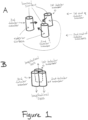
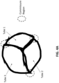
- FIG. 1 a structure that starts with three tubular members is shown, which ultimately results in a tri-leaflet prosthetic valve.
- the techniques described herein also can be applied to create a bi-leaflet prosthetic valve (i.e., starting with two tubular members; see, for example, FIGs. 1G and 1H ) or a quad-leaflet prosthetic valve (i.e., starting with four tubular members).
- the tri-leaflet valve shown in FIGs. 1A - 1F as well as in FIGs. 2-6 , 8A and 9A should be considered exemplary.
- each tubular member includes a first end and a second end, and has an exterior surface and a luminal surface (i.e., the inside surface of each tubular member), which define a longitudinal axis.
- the tubular members are positioned parallel to one another (i.e., aligned along their longitudinal axes).
- the tubular members that form the basis of the prosthetic valve described herein can be made from any material that is suitable for use in a prosthetic valve.
- suitable materials include, for example, native tissue material (e.g., native vessels), biologically-engineered material (e.g., Syedain et al., 2011, Biomaterials, 32(3):714-22 ; or Dahl et al., 2011, Sci. Transl. Med, 3(68):68ra9 ), synthetic material (e.g., Wu et al., 2012, Nat. Med., 18(7): 1148-53 ), or a combination thereof.
- native tissue material e.g., native vessels
- biologically-engineered material e.g., Syedain et al., 2011, Biomaterials, 32(3):714-22 ; or Dahl et al., 2011, Sci. Transl. Med, 3(68):68ra9
- synthetic material e.g., Wu et al., 2012, Nat. Med., 18
- the tubular members may include a degradable scaffold that can be seeded by extracellular matrix producing cells.
- the scaffold may be formed from fibrin, PLA, PGA, or other synthetic or biological polymer, and mixtures thereof.
- the ECM producing cells can be cultured with the scaffold, allowing the cells to produce ECM, which can in turn replace the degradable scaffold.
- the scaffold can be manipulated or processed to create alignment of the fibers in the ECM (e.g., an anisotropic matrix).
- the final product may be decellularized using detergents, dehydrated (e.g., freeze drying), or fixed / crosslinked (e.g., glutaraldehyde fixation) to create engineered tissue with or without cells.
- Some embodiments of the present disclosure may use the processes and engineered tissue as disclosed in the following: US 2007/061800 ; WO 2007/092902 ; US 2016/0203262 ; WO 2004/018008 ; WO 2004/101012 ; U.S. Patent No. 8,192,981 ; U.S. Patent No. 8,399,243 ; U.S. Patent No. 8,617,237 ; U.S. Patent No. 8,636,793 ; U.S. Patent No. 9,034,333 ; U.S. Patent No. 9,126,199 ; U.S. Serial No. 10/523,618 ; U.S. Serial No. 10/556,959 ; U.S. Serial No.
- the prosthetic valves described herein are not structurally constrained and can allow for growth, if an appropriate material and degradable sutures are used. This feature is particularly significant for pediatric application of the prosthetic valves described herein.
- tubular members of various diameters can be used to produce a given target diameter for the valve, which also will lead to leaflets having different areas. This feature is particularly relevant as it pertains to valve performance under specified pressure-flow conditions.
- the individual tubular members within a prosthetic valve as described herein can be made from different materials.
- one of the tubular members used in the starting materials can be a biologically engineered tubular member while the other tubular member used in the starting materials can be a synthetic tubular member.
- one of the starting tubular members in a tri-leaflet valve, can be a native tissue tubular member and the other two starting tubular members can be biologically-engineered tubular members. Virtually any combination of tubular members is envisioned.
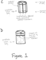
- FIG. 1C shows that each of the tubular members are attached to the adjacent tubular member(s) along a longitudinal seam.
- the longitudinal seam is located between the adjoining exterior surfaces of each tubular member.
- portions of the exterior surface of the adjoined tubular members form a circumferential wall of a prosthetic valve body.
- the prosthetic valve body Similar to each tubular member, the prosthetic valve body has a first end and a second end through which a longitudinal axis passes as well as an outer surface and an annulus.
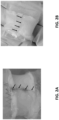
- FIGs. 2A and 2B are photographs showing the exterior of a prosthetic valve body in which the longitudinal seam can be seen (arrows).
- the longitudinal seam is shown vertically, while in FIG. 2B , the prosthetic valve body is shown horizontally, so the longitudinal seam is faintly detectable in the horizontal direction.
- FIG. 1D shows that each tubular member is then closed at its second end. Closure at the second end of each tubular member creates a leaflet (or a cusp), with the top surface of each leaflet (i.e., the surface at the first end of the valve body) formed from the luminal (or inside) surface of each tubular member ( FIG. 1E ). The bottom surface of each leaflet (i.e., the surface that projects toward the second end of the valve body) is formed from a portion of the exterior surface of each adjoined tubular member that does not form part of the circumferential wall ( FIG. 1E ).
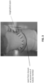
- FIG. 3 is a photograph showing the exterior of a prosthetic valve body in which the longitudinal seam can be seen (blue line to the far right of the body; arrows) as well as the closure at the second end of the tubular member (arrows).
- the closure at the second end of the tubular member is shown as an upwardly curved closure (e.g., concave, relative to the first end of the prosthetic valve body), but the closure could be a straight horizontal closure or a downwardly curved closure or any combination thereof.
- the position and directionality of the closure will determine, at least in part, the shape and structural configuration that is desired for each leaflet.
- Each leaflet has both a commissure region and an annular region.
- FIG. 4A is a schematic showing an end view (i.e., a view of the first-end) of a prosthetic valve as described herein and schematically demonstrating how the commissures are formed from the tubular members and the position of the longitudinal attachments.
- FIG. 4B is a photograph showing an end view (i.e., a view of the first-end) of a prosthetic valve as described herein and demonstrating the formation of the leaflets and commissures from the tubular members.
- FIG. 5 is a photograph showing an end view (i.e., a view of the second-end) of a prosthetic valve as described herein and showing the underside of each leaflet (i.e., the closed second ends of each tubular member).
- the arrows show the seam at the second end of one of the tubular members, which, when closed, produces the leaflet structure.
- FIGs. 6A - 6B shows another embodiment of a tri-tube design in which three tubes are sutured together in a closed ring and then the bottom of each tube is then sutured closed to form its own leaflet (only two of the axial suture lines connecting the three tubes together are clearly seen, along with the complete closure of one of the tubes creating one of the "leaflets").
- the design of the prosthetic valve described herein is intended to eliminate the most common site of failure of a valve that is made by suturing one tube inside another, where the load on the leaflets is transferred directly to the sutures used to attach the inner tube to the outer tube at the commissures.
- the commissure is created by adjacent tubular members, so the load on the leaflets is carried by the tubular member itself and not the sutures.
- suture pull-out which is another common problem with many of the currently used prosthetic valves, should not occur with the prosthetic valves described herein.
- Fatigue testing of the novel valve design described herein is presented demonstrating the superior commissure stability of the tri-tube design; pulse duplicator testing is presented showing acceptable valve function under pulmonary valve flow conditions in a juvenile sheep; and valve function upon implantation into the pulmonary artery of a juvenile sheep is show using ultrasonography (following compromise of the native pulmonary valve).
- Connecting or joining tissues and the various connectors for doing so are known in the art and include, without limitation, sutures or stitches, staples, adhesives (e.g. cyanoacrylate), or thermal fusion / welding.
- Such connectors can be used to attach tubular members to adjacent tubular members along a longitudinal seam or to close each tubular member at the second end as described herein.
- a prosthetic valve as described herein it may be desirable to include or attach a prosthetic valve as described herein to a solid support or solid structure. See, for example, FIG. 1F .
- the way in which a prosthetic valve as described herein can be attached to a solid support or a solid structure will be dependent upon the material(s) that each is made from.
- the same type of connectors for connecting or joining tissues that are described herein e.g., suture / stitches, staples, adhesives (e.g. cyanoacrylate), or thermal fusion / welding
- a biologically-engineered prosthetic valve as described herein can be generated on the solid support or solid structure such that the prosthetic valve becomes integral with the solid support or solid structure.
- FIGs. 1G and 1H demonstrate that the position of the leaflets within the valve body can be controlled by trimming or eliminating material from the tubular members.
- FIG. 1G shows that a small amount of material can be removed from the portion of the tubular members that is in the interior of the valve body (i.e., that does not form the wall of the valve body), which ultimately results in the leaflets being slightly recessed in the valve body relative to the first end.
- FIG. 1G shows that a small amount of material can be removed from the portion of the tubular members that is in the interior of the valve body (i.e., that does not form the wall of the valve body), which ultimately results in the leaflets being slightly recessed in the valve body relative to the first end.
- FIG. 1G shows that a small amount of material can be removed from the portion of the tubular members that is in the interior of the valve body (i.e., that does not form the wall of the valve body), which ultimately results in the leaflets being slightly recessed in the valve body relative to the first end.
- 1H shows that a larger amount of material can be removed from the portion of the tubular members that is in the interior of the valve body (i.e., that does not form the wall of the valve body), which ultimately results in the leaflets being positioned deeper in the valve body (e.g., halfway between the first and second ends, or nearer the second end than the first end of the valve body).
- the position of the leaflets within the valve body as described herein i.e., relative to the first and second ends of the valve body
- FIGS. 1G and 1H show two tubular members (i.e., a first and a second tubular member), the same concept of trimming or eliminating material to control the position of the valves within the prosthetic valve body can be applied to a prosthetic valve that includes three tubular members or four tubular members.
- one or more non-isodiametric tubular members can be used such that a sinus exists behind the leaflets.
- a sinus can be part of the normal valve anatomy when the diameter of the tube is increased in this region, and is considered important for normal valve hemodynamics.
- Tubular, cell-seeded fibrin gels were fabricated by mixing aqueous solutions of ovine dermal fibroblasts (ODFs, Coriell), bovine fibrinogen (Sigma), thrombin (Sigma), and calcium chloride.
- ODFs ovine dermal fibroblasts
- bovine fibrinogen Sigma
- thrombin Sigma
- calcium chloride The final component concentrations were as follows: 1 million ODFs/mL, 4 mg/mL fibrinogen, 0.38 U/mL thrombin, and 5.0 mM Ca ++ .
- the mixed solution was injected into tubular glass molds, which had a 16 mm inner diameter mandrel, a 4 mm annulus, and were 15 cm in total length.
- tubular fibrin gels on glass mandrels were cultured in DMEM + 10% fetal bovine serum (FBS, Hyclone), 100 U/mL penicillin, 100 ⁇ g/mL streptomycin, 0.25 ⁇ g/mL amphotericin B, 2 ⁇ g/mL insulin, and 50 ⁇ g/mL ascorbic acid. Culture medium was changed three times per week for 2 weeks while allowing the longitudinal shortening of the gels. The tissue tubes were then matured in a pulsed-flow-stretch bioreactor as described ( Syedain et al., 2011, Biomaterials, 32(3):714-22 ).
- FBS fetal bovine serum
- the biologically-engineered tubes were decellularized by immersion in 1% sodium dodecyl sulfate (SDS, Sigma) and 1% Triton X-100 (Sigma) for 6 hours and 30 minutes, respectively, at room temperature with continuous shaking. The tubes were then extensively rinsed in 1X phosphate buffered saline before and after overnight incubation in culture medium plus 2 U/mL deoxyribonuclease (Worthington Biochemical).
- SDS sodium dodecyl sulfate
- Triton X-100 Sigma
- Valves of 19 mm in diameter were fabricated using three of the 16 mm diameter biologically-engineered tubes. Each tube was cut to a length of 3 cm and a further trimmed to define a leaflet while providing for an outflow tract ( FIG. 6A ).
- the tubes were first sutured together into a closed ring using degradable sutures (Covidien Maxon CV) with three suture lines spanning the length along their point of contact (white dashed lines, FIG. 6A ). Then the bottom of each tube was sutured together to create a leaflet (yellow dashed lines, FIG. 6A ), yielding a tri-leaflet valve ( FIG. 6B ).
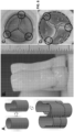
- the top view of a tube-in-tube valve and a tri-tube valve with the tubes color coded FIG. 6C, 6D ) facilitates comparison of commissure construction.
- Valves were mounted on custom silicone fixture and placed in Bose Durapulse TM System. Valves were tested at 20 Hz frequency with end diastolic pressure of 20 mm Hg to mimic pulmonary diastolic pressure gradients. One tube-in-tube valve and one tri-tube valve made from the same batch of biologically-engineered tubes were run for about 12 million (M) cycles prior to visual inspection.
- a customized pulse duplicator system as previously described (Reimer et al., 2015, Biomaterials, 62:88-94 ) was used. It consists of a commercial wave generator and pump (ViVitro Systems), a reservoir, valve mounting chamber, variable compliance chamber, and mechanical bi-leaflet valve to ensure one-directional fluid movement. The system had pressure transducers (ViVitro Systems) immediately above and below the valve to allow for accurate pressure measurements. Additionally, there was an electromagnetic flow meter (Carolina Medical, 500 series flow-meter) upstream of the valve to measure the flow rate in both directions. A custom Labview ® program was used to record flowrates and pressures.
- valve was sewn into two custom silicone sleeves that were then mounted in a custom chamber that allows for applying a transmural pressure gradient ( Reimer et al., 2015, Biomaterials, 62:88-94 ).
- the pulse duplicator loop was run with phosphate buffered saline as the test fluid.
- Each valve was tested with pressure conditions to mimic pulmonary pressure conditions at a prescribed flow rate (set by pump stroke volume and frequency). Average flow rate of 3.5 LPM was used to mimic pediatric cardiac output ( Cattermole et al., 2017, Physiol. Rep., 5(6):PMCID: 5371563 ). Pressure was controlled by changing the down-stream flow resistance, stroke volume, and up-stream hydraulic pressure head.
- end-on camera (Canon EOS T3i) images were obtained at 60 fps for video capture. Images extracted from the video were imported into ImageJ ® software to measure the open area of the valve during systole to report the geometric orifice area as percentage of total circular area for a given diameter.
- Strips with dimensions ⁇ 2 mm x ⁇ 10 mm were cut from the biologically-engineered tube in the circumferential and axial directions and tested in tensile strain-to failure as previously described ( Syedain et al., 2015, Biomaterials, 73:175-84 ; Reimer et al., 2015, Biomaterials, 62:88-94 ). Briefly, sample dimensions were measured prior to testing using a digital caliper. The strips were mounted in custom grips attached to the actuator arms of an Instron tensile testing system (Instron Systems) and straightened with a 0.02 N tensile load. Strain was calculated by taking the natural logarithm of the sample's deformed length over its initial length. Stress was defined as the force divided by the un-deformed, cross-sectional area of the strip. Modulus and ultimate tensile strength (UTS) were taken as the slope of the linear region of the stress-strain curve and the maximum stress recorded, respectively.
- suture pull-out force was measured by placing a loop of 7-0 suture 2 mm from the edge of a strip that is cut 1 cm x 1 cm. One end of the loop is clamped to a stationary arm and the other end is connected to the actuator arm of an Instron tensile testing system (Instron Systems). The loop was pulled to failure at a rate of 5 mm/sec.
- leaflet samples approximately 5 mm x 5 mm were collected to measure collagen content biochemically.
- Collagen content is quantified using the hydroxyproline assay and a conversion factor of 7.46 mg of collagen per mg of 4-hydroxyproline.
- a graft sample was acid hydrolyzed and dissolved collagen was bound to dimethylaminobenzaldehyde (p-DMBA) as a colorimetric detector.
- p-DMBA dimethylaminobenzaldehyde
- hydrolyzed graft samples and hydroxyproline standards were read at 550 nm wavelength in a BioRad plate detection system. Starting sample volumes were calculated using the measured length, width, and thickness of each sample. Collagen contents were reported as collagen mass per unit volume in each sample.
- Implantations were performed at the University of Minnesota Experimental Surgical Services (ESS).
- the heart was exposed via a left lateral thoracotomy with dissection through the intercostal space.
- the decellularized tissue tubes possessed tensile strength comparable to ovine pulmonary valve leaflets and to the standard-of-care for pediatric pulmonary valve replacement, the Contegra TM valved conduit, which is a cross-linked bovine jugular vein valve.
- the tensile stiffness of the tubes was comparable to the native leaflet and lower than a Contegra leaflet.
- Decellularized tissue histology shows collagen bands (stained green) aligned in the circumferential direction with remnant fibrin (stained red) on luminal surface ( FIG. 7D ).
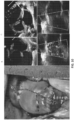
- FIG. 8A Wear resistance was assessed in accelerated fatigue testing using a Bose Durapulse TM System after 12 M cycles (equivalent to 20 wk in vivo ) with 20 mm Hg end diastolic pressure drop ( FIG. 8A ). Commissure damage was clearly evident in the tube-in-tube design at the suture sites connecting the inner and outer tubes at the commissures ( FIG. 8A ), but not in the novel tri-tube design ( FIG. 8B ) where the commissures are formed by adjoining tubes ( FIG. 6A-6C ).
- Systolic pressure drop across the valves was ⁇ 5 mm Hg except in one animal where a narrow distal anastomosis, as sutured, created a systolic pressure drop of 15 mm Hg.
- Table 2. Ultrasound Assessment of Implanted Tri-tube Valve at 1 Week Post-Implantation Animal ID Cardiac Output (LPM) Mean Systolic ⁇ P (mm Hg) Effective Orifice Area (cm 2 ) Pulmonary Insufficiency Index PACV 1 4.1 15 a 0.88 Trivial PACV 2 7.2 5 1.37 Trivial PACV 3 4.2 2 0.92 Trivial PACV 4 4.9 3 0.94 Trivial a Systolic pressure was high due to cinching at distal anastomotic suture line
Landscapes
- Health & Medical Sciences (AREA)
- Engineering & Computer Science (AREA)
- Biomedical Technology (AREA)
- Cardiology (AREA)
- Heart & Thoracic Surgery (AREA)
- Oral & Maxillofacial Surgery (AREA)
- Transplantation (AREA)
- Vascular Medicine (AREA)
- Life Sciences & Earth Sciences (AREA)
- Animal Behavior & Ethology (AREA)
- General Health & Medical Sciences (AREA)
- Public Health (AREA)
- Veterinary Medicine (AREA)
- Manufacturing & Machinery (AREA)
- Mechanical Engineering (AREA)
- Prostheses (AREA)
Applications Claiming Priority (2)
| Application Number | Priority Date | Filing Date | Title |
|---|---|---|---|
| US201762482500P | 2017-04-06 | 2017-04-06 | |
| PCT/US2018/026502 WO2018187714A1 (en) | 2017-04-06 | 2018-04-06 | Prosthetic valves and methods of making |
Publications (3)
| Publication Number | Publication Date |
|---|---|
| EP3606467A1 EP3606467A1 (en) | 2020-02-12 |
| EP3606467A4 EP3606467A4 (en) | 2021-06-23 |
| EP3606467B1 true EP3606467B1 (en) | 2023-06-14 |
Family
ID=63713143
Family Applications (1)
| Application Number | Title | Priority Date | Filing Date |
|---|---|---|---|
| EP18780763.1A Active EP3606467B1 (en) | 2017-04-06 | 2018-04-06 | Prosthetic valves and methods of making |
Country Status (11)
| Country | Link |
|---|---|
| US (2) | US11589982B2 (es) |
| EP (1) | EP3606467B1 (es) |
| KR (1) | KR102536223B1 (es) |
| AU (2) | AU2018249598B9 (es) |
| DK (1) | DK3606467T3 (es) |
| ES (1) | ES2955864T3 (es) |
| FI (1) | FI3606467T3 (es) |
| HU (1) | HUE064927T2 (es) |
| PL (1) | PL3606467T3 (es) |
| PT (1) | PT3606467T (es) |
| WO (1) | WO2018187714A1 (es) |
Families Citing this family (7)
| Publication number | Priority date | Publication date | Assignee | Title |
|---|---|---|---|---|
| US10507101B2 (en) | 2014-10-13 | 2019-12-17 | W. L. Gore & Associates, Inc. | Valved conduit |
| US11406533B2 (en) | 2017-03-17 | 2022-08-09 | W. L. Gore & Associates, Inc. | Integrated aqueous shunt for glaucoma treatment |
| AU2018291035B2 (en) * | 2017-06-30 | 2021-07-08 | Mark LAUREN | Regenerative tissue and natural tissue implants |
| JP7202374B2 (ja) | 2017-10-31 | 2023-01-11 | ダブリュ.エル.ゴア アンド アソシエイツ,インコーポレイティド | 弁付き導管 |
| USD977642S1 (en) | 2018-10-29 | 2023-02-07 | W. L. Gore & Associates, Inc. | Pulmonary valve conduit |
| US11678983B2 (en) | 2018-12-12 | 2023-06-20 | W. L. Gore & Associates, Inc. | Implantable component with socket |
| WO2024059294A1 (en) * | 2022-09-15 | 2024-03-21 | Regents Of The University Of Minnesota | Biologically-engineered pediatric valved conduit and methods of making and using |
Family Cites Families (33)
| Publication number | Priority date | Publication date | Assignee | Title |
|---|---|---|---|---|
| US5713950A (en) | 1993-11-01 | 1998-02-03 | Cox; James L. | Method of replacing heart valves using flexible tubes |
| US6241763B1 (en) * | 1999-06-08 | 2001-06-05 | William J. Drasler | In situ venous valve device and method of formation |
| DE60128069D1 (de) * | 2000-01-31 | 2007-06-06 | Cook Biotech Inc | Stentventilklappen |
| US7160320B2 (en) * | 2002-04-16 | 2007-01-09 | The International Heart Institute Of Montana Foundation | Reed valve for implantation into mammalian blood vessels and heart with optional temporary or permanent support |
| DE10235237A1 (de) | 2002-08-01 | 2004-02-12 | Symetis Ag | In-vitro-Verfahren zum Herstellen einer homologen "gestenteten" Tissue eingineerten Herzklappe |
| DE10322024A1 (de) | 2003-05-16 | 2004-12-02 | Symetis Ag | Bioreaktor zum Herstellen einer Gewebeprothese, insbesondere Herzklappe |
| EP1693025A1 (en) | 2005-02-17 | 2006-08-23 | Universität Zürich | Method of manufacturing a tissue-engineered prosthesis |
| CN1928818A (zh) | 2005-09-09 | 2007-03-14 | 鸿富锦精密工业(深圳)有限公司 | 网络装置及其软件更新方法 |
| GB0523950D0 (en) | 2005-11-24 | 2006-01-04 | Symetis Ag | Bioreactor system |
| CA2641612A1 (en) | 2006-02-07 | 2007-08-16 | Organogenesis, Inc. | Bioengineered tissue constructs and cardiac uses thereof |
| US20140035805A1 (en) | 2009-04-02 | 2014-02-06 | David MINNEN | Spatial operating environment (soe) with markerless gestural control |
| EP1958598A1 (de) | 2007-02-16 | 2008-08-20 | Universität Zürich | Wachstumsfähige, rohrförmige Stützprothese |
| WO2008098777A1 (de) | 2007-02-16 | 2008-08-21 | Universität Zürich | Rohrförmige stützprothese mit herzklappe insbesondere für aortenklappenersatz |
| AU2008282922B2 (en) | 2007-07-27 | 2014-01-16 | Humacyte, Inc. | Compositions comprising human collagen and human elastin and methods for soft tissue augmentation |
| US8473064B2 (en) | 2008-06-18 | 2013-06-25 | Accelerated Care Plus Corp. | Electrical stimulation method for reduction of joint compression |
| EP2342317B1 (en) | 2008-09-22 | 2012-12-19 | University Of Zurich Prorektorat Forschung | Hanging drop plate |
| WO2010115185A1 (en) | 2009-04-03 | 2010-10-07 | Xcellerex, Inc. | Tissue and organ graft bioreactor and method of operation |
| EP2432495B1 (en) | 2009-05-20 | 2017-03-22 | Humacyte, Inc. | Elastin for soft tissue augmentation |
| KR101258213B1 (ko) * | 2010-07-07 | 2013-04-25 | 신경민 | 심낭을 이용한 인공심장판막도관 및 제조방법 |
| WO2012025636A1 (en) | 2010-08-27 | 2012-03-01 | University Of Zurich | Method for target and drug validation in inflammatory and/or cardiovascular diseases |
| JP2014507179A (ja) * | 2010-12-14 | 2014-03-27 | コリブリ ハート バルブ エルエルシー | 統合された弁尖を伴う折り畳まれた膜の心臓弁膜尖を含む経皮的にデリバリー可能な心臓弁 |
| US20130013083A1 (en) | 2011-01-06 | 2013-01-10 | Humacyte | Tissue-Engineered Constructs |
| CA2822689C (en) | 2011-01-06 | 2015-12-29 | Humacyte | Tissue-engineered constructs |
| TR201905539T4 (tr) | 2011-10-14 | 2019-05-21 | Humacyte Inc | Tübüler protez. |
| EP2828372A1 (en) | 2012-03-23 | 2015-01-28 | Cytograft Tissue Engineering, Inc. | Tissue-engineered heart valve for transcatheter repair |
| US10111740B2 (en) | 2012-08-21 | 2018-10-30 | Regents Of The University Of Minnesota | Decellularized biologically-engineered tubular grafts |
| US20140277416A1 (en) * | 2013-03-14 | 2014-09-18 | Robert Matheny | Seamless Tubular Extracellular Matrix Prosthetic Valve and Method for Forming Same |
| US20160203262A1 (en) | 2013-08-23 | 2016-07-14 | President And Fellows Of Harvard College | System and Method for Determining Quality of Stem Cell Derived Cardiac Myocytes |
| US10321987B2 (en) | 2014-04-23 | 2019-06-18 | Medtronic, Inc. | Paravalvular leak resistant prosthetic heart valve system |
| WO2015169866A1 (en) * | 2014-05-06 | 2015-11-12 | Dsm Ip Assets B.V. | Prosthetic valve and method of making a prosthetic valve |
| WO2015169869A1 (en) * | 2014-05-06 | 2015-11-12 | Dsm Ip Assets B.V. | Method of making a prosthetic valve and valve obtained therewith |
| PT3193781T (pt) | 2014-09-18 | 2021-06-03 | Humacyte Inc | Métodos e aparelhos para formar tubos fibrosos |
| US20220168099A1 (en) | 2019-05-28 | 2022-06-02 | Regents Of The University Of Minnesota | An engineered valve and method of making |
-
2018
- 2018-04-06 AU AU2018249598A patent/AU2018249598B9/en active Active
- 2018-04-06 DK DK18780763.1T patent/DK3606467T3/da active
- 2018-04-06 FI FIEP18780763.1T patent/FI3606467T3/fi active
- 2018-04-06 ES ES18780763T patent/ES2955864T3/es active Active
- 2018-04-06 EP EP18780763.1A patent/EP3606467B1/en active Active
- 2018-04-06 US US16/500,147 patent/US11589982B2/en active Active
- 2018-04-06 WO PCT/US2018/026502 patent/WO2018187714A1/en unknown
- 2018-04-06 PL PL18780763.1T patent/PL3606467T3/pl unknown
- 2018-04-06 HU HUE18780763A patent/HUE064927T2/hu unknown
- 2018-04-06 PT PT187807631T patent/PT3606467T/pt unknown
- 2018-04-06 KR KR1020197032315A patent/KR102536223B1/ko active IP Right Grant
-
2023
- 2023-02-27 US US18/114,881 patent/US20240058119A1/en active Pending
- 2023-11-13 AU AU2023265966A patent/AU2023265966A1/en active Pending
Also Published As
| Publication number | Publication date |
|---|---|
| AU2023265966A1 (en) | 2023-12-07 |
| ES2955864T3 (es) | 2023-12-07 |
| US20240058119A1 (en) | 2024-02-22 |
| KR102536223B1 (ko) | 2023-05-23 |
| US11589982B2 (en) | 2023-02-28 |
| EP3606467A4 (en) | 2021-06-23 |
| WO2018187714A1 (en) | 2018-10-11 |
| AU2018249598A1 (en) | 2019-10-10 |
| AU2018249598B2 (en) | 2023-07-13 |
| DK3606467T3 (da) | 2023-09-11 |
| PT3606467T (pt) | 2023-09-14 |
| AU2018249598B9 (en) | 2023-07-27 |
| FI3606467T3 (fi) | 2023-09-08 |
| HUE064927T2 (hu) | 2024-04-28 |
| PL3606467T3 (pl) | 2023-12-11 |
| US20210100653A1 (en) | 2021-04-08 |
| EP3606467A1 (en) | 2020-02-12 |
| KR20190130648A (ko) | 2019-11-22 |
Similar Documents
| Publication | Publication Date | Title |
|---|---|---|
| EP3606467B1 (en) | Prosthetic valves and methods of making | |
| Reimer et al. | Implantation of a tissue-engineered tubular heart valve in growing lambs | |
| AU726577B2 (en) | Heart valve replacement using flexible tubes | |
| Syedain et al. | Tubular heart valves from decellularized engineered tissue | |
| NL2009145C2 (en) | Implant. | |
| US9675450B2 (en) | Pericardial heart valve replacement and methods of constructing the same | |
| US20150088247A1 (en) | Tissue-engineered heart valve for transcatheter repair | |
| WO2001030274A1 (fr) | Valve cardiaque mecanique et procede de production | |
| JP2005502429A (ja) | 医療装置のための高分子弁膜構造 | |
| Takewa et al. | In vivo evaluation of an in-body, tissue-engineered, completely autologous valved conduit (biovalve type VI) as an aortic valve in a goat model | |
| Morsi et al. | Artificial aortic valves: an overview | |
| Schaefermeier et al. | Design and fabrication of three-dimensional scaffolds for tissue engineering of human heart valves | |
| US20220168099A1 (en) | An engineered valve and method of making | |
| WO1997024083A1 (en) | Method of replacing heart valves using flexible tubes | |
| JP2022529472A (ja) | 自然に設計された僧帽弁プロテーゼ | |
| Buse et al. | Pulse duplicator hydrodynamic testing of bioengineered biological heart valves | |
| WO2024059294A1 (en) | Biologically-engineered pediatric valved conduit and methods of making and using | |
| WO2024059281A1 (en) | Improved valve incorporating constructed tissue | |
| Brougham | The Development of a Fibrin-Collagen-Glycosaminoglycan Scaffold for Heart Valve Tissue Engineering | |
| CN116725738A (zh) | 瓣膜支架及人工心脏瓣膜 | |
| AU774141B2 (en) | Heart valve replacement |
Legal Events
| Date | Code | Title | Description |
|---|---|---|---|
| STAA | Information on the status of an ep patent application or granted ep patent |
Free format text: STATUS: THE INTERNATIONAL PUBLICATION HAS BEEN MADE |
|
| PUAI | Public reference made under article 153(3) epc to a published international application that has entered the european phase |
Free format text: ORIGINAL CODE: 0009012 |
|
| STAA | Information on the status of an ep patent application or granted ep patent |
Free format text: STATUS: REQUEST FOR EXAMINATION WAS MADE |
|
| 17P | Request for examination filed |
Effective date: 20191105 |
|
| AK | Designated contracting states |
Kind code of ref document: A1 Designated state(s): AL AT BE BG CH CY CZ DE DK EE ES FI FR GB GR HR HU IE IS IT LI LT LU LV MC MK MT NL NO PL PT RO RS SE SI SK SM TR |
|
| AX | Request for extension of the european patent |
Extension state: BA ME |
|
| RAP1 | Party data changed (applicant data changed or rights of an application transferred) |
Owner name: REGENTS OF THE UNIVERSITY OF MINNESOTA |
|
| RIN1 | Information on inventor provided before grant (corrected) |
Inventor name: TRANQUILLO, ROBERT Inventor name: SYEDAIN, ZEESHAN |
|
| DAV | Request for validation of the european patent (deleted) | ||
| DAX | Request for extension of the european patent (deleted) | ||
| REG | Reference to a national code |
Ref country code: DE Ref legal event code: R079 Ref document number: 602018051880 Country of ref document: DE Free format text: PREVIOUS MAIN CLASS: A61F0002060000 Ipc: A61F0002240000 |
|
| A4 | Supplementary search report drawn up and despatched |
Effective date: 20210521 |
|
| RIC1 | Information provided on ipc code assigned before grant |
Ipc: A61F 2/24 20060101AFI20210517BHEP Ipc: B29C 57/10 20060101ALN20210517BHEP |
|
| GRAP | Despatch of communication of intention to grant a patent |
Free format text: ORIGINAL CODE: EPIDOSNIGR1 |
|
| STAA | Information on the status of an ep patent application or granted ep patent |
Free format text: STATUS: GRANT OF PATENT IS INTENDED |
|
| INTG | Intention to grant announced |
Effective date: 20230105 |
|
| GRAS | Grant fee paid |
Free format text: ORIGINAL CODE: EPIDOSNIGR3 |
|
| GRAA | (expected) grant |
Free format text: ORIGINAL CODE: 0009210 |
|
| STAA | Information on the status of an ep patent application or granted ep patent |
Free format text: STATUS: THE PATENT HAS BEEN GRANTED |
|
| AK | Designated contracting states |
Kind code of ref document: B1 Designated state(s): AL AT BE BG CH CY CZ DE DK EE ES FI FR GB GR HR HU IE IS IT LI LT LU LV MC MK MT NL NO PL PT RO RS SE SI SK SM TR |
|
| P01 | Opt-out of the competence of the unified patent court (upc) registered |
Effective date: 20230426 |
|
| REG | Reference to a national code |
Ref country code: CH Ref legal event code: EP |
|
| REG | Reference to a national code |
Ref country code: DE Ref legal event code: R096 Ref document number: 602018051880 Country of ref document: DE |
|
| REG | Reference to a national code |
Ref country code: AT Ref legal event code: REF Ref document number: 1578681 Country of ref document: AT Kind code of ref document: T Effective date: 20230715 |
|
| REG | Reference to a national code |
Ref country code: DK Ref legal event code: T3 Effective date: 20230908 |
|
| REG | Reference to a national code |
Ref country code: PT Ref legal event code: SC4A Ref document number: 3606467 Country of ref document: PT Date of ref document: 20230914 Kind code of ref document: T Free format text: AVAILABILITY OF NATIONAL TRANSLATION Effective date: 20230911 |
|
| REG | Reference to a national code |
Ref country code: NL Ref legal event code: FP |
|
| REG | Reference to a national code |
Ref country code: LT Ref legal event code: MG9D |
|
| REG | Reference to a national code |
Ref country code: NO Ref legal event code: T2 Effective date: 20230614 |
|
| PG25 | Lapsed in a contracting state [announced via postgrant information from national office to epo] |
Ref country code: SE Free format text: LAPSE BECAUSE OF FAILURE TO SUBMIT A TRANSLATION OF THE DESCRIPTION OR TO PAY THE FEE WITHIN THE PRESCRIBED TIME-LIMIT Effective date: 20230614 |
|
| PG25 | Lapsed in a contracting state [announced via postgrant information from national office to epo] |
Ref country code: RS Free format text: LAPSE BECAUSE OF FAILURE TO SUBMIT A TRANSLATION OF THE DESCRIPTION OR TO PAY THE FEE WITHIN THE PRESCRIBED TIME-LIMIT Effective date: 20230614 Ref country code: LV Free format text: LAPSE BECAUSE OF FAILURE TO SUBMIT A TRANSLATION OF THE DESCRIPTION OR TO PAY THE FEE WITHIN THE PRESCRIBED TIME-LIMIT Effective date: 20230614 Ref country code: LT Free format text: LAPSE BECAUSE OF FAILURE TO SUBMIT A TRANSLATION OF THE DESCRIPTION OR TO PAY THE FEE WITHIN THE PRESCRIBED TIME-LIMIT Effective date: 20230614 Ref country code: HR Free format text: LAPSE BECAUSE OF FAILURE TO SUBMIT A TRANSLATION OF THE DESCRIPTION OR TO PAY THE FEE WITHIN THE PRESCRIBED TIME-LIMIT Effective date: 20230614 Ref country code: GR Free format text: LAPSE BECAUSE OF FAILURE TO SUBMIT A TRANSLATION OF THE DESCRIPTION OR TO PAY THE FEE WITHIN THE PRESCRIBED TIME-LIMIT Effective date: 20230915 |
|
| REG | Reference to a national code |
Ref country code: ES Ref legal event code: FG2A Ref document number: 2955864 Country of ref document: ES Kind code of ref document: T3 Effective date: 20231207 |
|
| PG25 | Lapsed in a contracting state [announced via postgrant information from national office to epo] |
Ref country code: SK Free format text: LAPSE BECAUSE OF FAILURE TO SUBMIT A TRANSLATION OF THE DESCRIPTION OR TO PAY THE FEE WITHIN THE PRESCRIBED TIME-LIMIT Effective date: 20230614 |
|
| PG25 | Lapsed in a contracting state [announced via postgrant information from national office to epo] |
Ref country code: IS Free format text: LAPSE BECAUSE OF FAILURE TO SUBMIT A TRANSLATION OF THE DESCRIPTION OR TO PAY THE FEE WITHIN THE PRESCRIBED TIME-LIMIT Effective date: 20231014 |
|
| PG25 | Lapsed in a contracting state [announced via postgrant information from national office to epo] |
Ref country code: SM Free format text: LAPSE BECAUSE OF FAILURE TO SUBMIT A TRANSLATION OF THE DESCRIPTION OR TO PAY THE FEE WITHIN THE PRESCRIBED TIME-LIMIT Effective date: 20230614 Ref country code: SK Free format text: LAPSE BECAUSE OF FAILURE TO SUBMIT A TRANSLATION OF THE DESCRIPTION OR TO PAY THE FEE WITHIN THE PRESCRIBED TIME-LIMIT Effective date: 20230614 Ref country code: RO Free format text: LAPSE BECAUSE OF FAILURE TO SUBMIT A TRANSLATION OF THE DESCRIPTION OR TO PAY THE FEE WITHIN THE PRESCRIBED TIME-LIMIT Effective date: 20230614 Ref country code: IS Free format text: LAPSE BECAUSE OF FAILURE TO SUBMIT A TRANSLATION OF THE DESCRIPTION OR TO PAY THE FEE WITHIN THE PRESCRIBED TIME-LIMIT Effective date: 20231014 Ref country code: EE Free format text: LAPSE BECAUSE OF FAILURE TO SUBMIT A TRANSLATION OF THE DESCRIPTION OR TO PAY THE FEE WITHIN THE PRESCRIBED TIME-LIMIT Effective date: 20230614 Ref country code: CZ Free format text: LAPSE BECAUSE OF FAILURE TO SUBMIT A TRANSLATION OF THE DESCRIPTION OR TO PAY THE FEE WITHIN THE PRESCRIBED TIME-LIMIT Effective date: 20230614 |
|
| REG | Reference to a national code |
Ref country code: DE Ref legal event code: R097 Ref document number: 602018051880 Country of ref document: DE |
|
| PLBE | No opposition filed within time limit |
Free format text: ORIGINAL CODE: 0009261 |
|
| STAA | Information on the status of an ep patent application or granted ep patent |
Free format text: STATUS: NO OPPOSITION FILED WITHIN TIME LIMIT |
|
| REG | Reference to a national code |
Ref country code: HU Ref legal event code: AG4A Ref document number: E064927 Country of ref document: HU |
|
| PGFP | Annual fee paid to national office [announced via postgrant information from national office to epo] |
Ref country code: PT Payment date: 20240325 Year of fee payment: 7 |
|
| PG25 | Lapsed in a contracting state [announced via postgrant information from national office to epo] |
Ref country code: SI Free format text: LAPSE BECAUSE OF FAILURE TO SUBMIT A TRANSLATION OF THE DESCRIPTION OR TO PAY THE FEE WITHIN THE PRESCRIBED TIME-LIMIT Effective date: 20230614 |
|
| PGFP | Annual fee paid to national office [announced via postgrant information from national office to epo] |
Ref country code: NL Payment date: 20240426 Year of fee payment: 7 |
|
| 26N | No opposition filed |
Effective date: 20240315 |