EP3606397B1 - Stereoscopic optical system of a surgical instrument and method for producing same - Google Patents
Stereoscopic optical system of a surgical instrument and method for producing same Download PDFInfo
- Publication number
- EP3606397B1 EP3606397B1 EP18717244.0A EP18717244A EP3606397B1 EP 3606397 B1 EP3606397 B1 EP 3606397B1 EP 18717244 A EP18717244 A EP 18717244A EP 3606397 B1 EP3606397 B1 EP 3606397B1
- Authority
- EP
- European Patent Office
- Prior art keywords
- stator
- distal
- proximal
- coil
- pole shoe
- Prior art date
- Legal status (The legal status is an assumption and is not a legal conclusion. Google has not performed a legal analysis and makes no representation as to the accuracy of the status listed.)
- Active
Links
- 230000003287 optical effect Effects 0.000 title claims description 139
- 238000004519 manufacturing process Methods 0.000 title claims description 9
- 230000005291 magnetic effect Effects 0.000 claims description 38
- 230000005672 electromagnetic field Effects 0.000 claims description 16
- 239000003302 ferromagnetic material Substances 0.000 claims description 6
- 238000000034 method Methods 0.000 claims description 6
- 230000005298 paramagnetic effect Effects 0.000 claims description 6
- 238000001746 injection moulding Methods 0.000 claims description 5
- 239000011159 matrix material Substances 0.000 claims description 5
- 239000002907 paramagnetic material Substances 0.000 claims description 5
- 239000004033 plastic Substances 0.000 claims description 5
- 239000002245 particle Substances 0.000 claims description 3
- 230000000712 assembly Effects 0.000 description 17
- 238000000429 assembly Methods 0.000 description 17
- 238000009434 installation Methods 0.000 description 10
- 239000006249 magnetic particle Substances 0.000 description 6
- 239000000463 material Substances 0.000 description 6
- 230000003068 static effect Effects 0.000 description 6
- 239000000853 adhesive Substances 0.000 description 5
- 230000001070 adhesive effect Effects 0.000 description 5
- 230000004907 flux Effects 0.000 description 4
- 230000008859 change Effects 0.000 description 3
- 238000010276 construction Methods 0.000 description 3
- XEEYBQQBJWHFJM-UHFFFAOYSA-N Iron Chemical compound [Fe] XEEYBQQBJWHFJM-UHFFFAOYSA-N 0.000 description 2
- 230000001419 dependent effect Effects 0.000 description 2
- 238000003384 imaging method Methods 0.000 description 2
- 239000000243 solution Substances 0.000 description 2
- 229910052779 Neodymium Inorganic materials 0.000 description 1
- 239000004020 conductor Substances 0.000 description 1
- 230000008878 coupling Effects 0.000 description 1
- 238000010168 coupling process Methods 0.000 description 1
- 238000005859 coupling reaction Methods 0.000 description 1
- 230000000694 effects Effects 0.000 description 1
- 230000005520 electrodynamics Effects 0.000 description 1
- 239000003822 epoxy resin Substances 0.000 description 1
- 210000003746 feather Anatomy 0.000 description 1
- 229910052742 iron Inorganic materials 0.000 description 1
- 239000000696 magnetic material Substances 0.000 description 1
- 239000000203 mixture Substances 0.000 description 1
- QEFYFXOXNSNQGX-UHFFFAOYSA-N neodymium atom Chemical compound [Nd] QEFYFXOXNSNQGX-UHFFFAOYSA-N 0.000 description 1
- 229910001172 neodymium magnet Inorganic materials 0.000 description 1
- 229920000647 polyepoxide Polymers 0.000 description 1
- 230000008569 process Effects 0.000 description 1
- 230000003313 weakening effect Effects 0.000 description 1
Images


Classifications
-
- H—ELECTRICITY
- H02—GENERATION; CONVERSION OR DISTRIBUTION OF ELECTRIC POWER
- H02K—DYNAMO-ELECTRIC MACHINES
- H02K33/00—Motors with reciprocating, oscillating or vibrating magnet, armature or coil system
- H02K33/18—Motors with reciprocating, oscillating or vibrating magnet, armature or coil system with coil systems moving upon intermittent or reversed energisation thereof by interaction with a fixed field system, e.g. permanent magnets
-
- A—HUMAN NECESSITIES
- A61—MEDICAL OR VETERINARY SCIENCE; HYGIENE
- A61B—DIAGNOSIS; SURGERY; IDENTIFICATION
- A61B1/00—Instruments for performing medical examinations of the interior of cavities or tubes of the body by visual or photographical inspection, e.g. endoscopes; Illuminating arrangements therefor
- A61B1/00064—Constructional details of the endoscope body
- A61B1/00071—Insertion part of the endoscope body
- A61B1/0008—Insertion part of the endoscope body characterised by distal tip features
- A61B1/00096—Optical elements
-
- A—HUMAN NECESSITIES
- A61—MEDICAL OR VETERINARY SCIENCE; HYGIENE
- A61B—DIAGNOSIS; SURGERY; IDENTIFICATION
- A61B1/00—Instruments for performing medical examinations of the interior of cavities or tubes of the body by visual or photographical inspection, e.g. endoscopes; Illuminating arrangements therefor
- A61B1/00163—Optical arrangements
- A61B1/00193—Optical arrangements adapted for stereoscopic vision
-
- G—PHYSICS
- G02—OPTICS
- G02B—OPTICAL ELEMENTS, SYSTEMS OR APPARATUS
- G02B23/00—Telescopes, e.g. binoculars; Periscopes; Instruments for viewing the inside of hollow bodies; Viewfinders; Optical aiming or sighting devices
- G02B23/24—Instruments or systems for viewing the inside of hollow bodies, e.g. fibrescopes
- G02B23/2407—Optical details
- G02B23/2415—Stereoscopic endoscopes
-
- G—PHYSICS
- G02—OPTICS
- G02B—OPTICAL ELEMENTS, SYSTEMS OR APPARATUS
- G02B23/00—Telescopes, e.g. binoculars; Periscopes; Instruments for viewing the inside of hollow bodies; Viewfinders; Optical aiming or sighting devices
- G02B23/24—Instruments or systems for viewing the inside of hollow bodies, e.g. fibrescopes
- G02B23/2407—Optical details
- G02B23/2423—Optical details of the distal end
- G02B23/243—Objectives for endoscopes
-
- G—PHYSICS
- G02—OPTICS
- G02B—OPTICAL ELEMENTS, SYSTEMS OR APPARATUS
- G02B30/00—Optical systems or apparatus for producing three-dimensional [3D] effects, e.g. stereoscopic images
- G02B30/20—Optical systems or apparatus for producing three-dimensional [3D] effects, e.g. stereoscopic images by providing first and second parallax images to an observer's left and right eyes
- G02B30/22—Optical systems or apparatus for producing three-dimensional [3D] effects, e.g. stereoscopic images by providing first and second parallax images to an observer's left and right eyes of the stereoscopic type
- G02B30/25—Optical systems or apparatus for producing three-dimensional [3D] effects, e.g. stereoscopic images by providing first and second parallax images to an observer's left and right eyes of the stereoscopic type using polarisation techniques
-
- G—PHYSICS
- G02—OPTICS
- G02B—OPTICAL ELEMENTS, SYSTEMS OR APPARATUS
- G02B7/00—Mountings, adjusting means, or light-tight connections, for optical elements
- G02B7/02—Mountings, adjusting means, or light-tight connections, for optical elements for lenses
- G02B7/04—Mountings, adjusting means, or light-tight connections, for optical elements for lenses with mechanism for focusing or varying magnification
- G02B7/06—Focusing binocular pairs
-
- G—PHYSICS
- G02—OPTICS
- G02B—OPTICAL ELEMENTS, SYSTEMS OR APPARATUS
- G02B7/00—Mountings, adjusting means, or light-tight connections, for optical elements
- G02B7/02—Mountings, adjusting means, or light-tight connections, for optical elements for lenses
- G02B7/04—Mountings, adjusting means, or light-tight connections, for optical elements for lenses with mechanism for focusing or varying magnification
- G02B7/08—Mountings, adjusting means, or light-tight connections, for optical elements for lenses with mechanism for focusing or varying magnification adapted to co-operate with a remote control mechanism
-
- H—ELECTRICITY
- H01—ELECTRIC ELEMENTS
- H01F—MAGNETS; INDUCTANCES; TRANSFORMERS; SELECTION OF MATERIALS FOR THEIR MAGNETIC PROPERTIES
- H01F7/00—Magnets
- H01F7/06—Electromagnets; Actuators including electromagnets
- H01F7/08—Electromagnets; Actuators including electromagnets with armatures
- H01F7/16—Rectilinearly-movable armatures
- H01F7/1607—Armatures entering the winding
- H01F7/1615—Armatures or stationary parts of magnetic circuit having permanent magnet
Definitions
- the invention relates to a stereoscopic optical system of a surgical instrument, comprising a left optical channel, a right optical channel and an electromagnetic actuator with a stator and a rotor.
- the invention also relates to a surgical instrument and a method for producing a stereoscopic optical system of a surgical instrument, with a left optical channel, a right optical channel and an electromagnetic actuator with a stator and a rotor.
- Electromagnetic actuators have a wide variety of uses. For example, they can be used to operate switches or set or adjust micro-optics. In the case of surgical instruments, for example endoscopes, these compact actuators can be used to change a focus or a magnification of an optical system. For endoscopes with With a variable viewing direction, it is also possible to set or change a viewing direction of the optical system with the aid of an electromagnetic actuator.
- the change in the optical properties of an optical system takes place in that an optical component, for example a lens, a prism or a diaphragm, is displaced through the actuator, the optical component being located in or on the runner of the actuator.
- bistable and monostable electromagnetic actuators There are known bistable and monostable electromagnetic actuators.
- a bistable electromagnetic actuator has a rotor that is held in a permanent magnetic field in one of two extreme positions (end positions) and can be transferred from one of these two stable positions to the other stable position by switching an electromagnetic field.
- the rotor In the case of a monostable electromagnetic actuator, the rotor is held in a stable position in its rest position by a magnetic field which is generated by one or more permanent magnets. By applying an electromagnetic field generated by a magnetic coil, the rotor is moved out of this stable position of rest.
- Bistable systems are particularly suitable for two-stage operation with end positions held without power.
- Monostable systems are well suited for continuous adjustment.
- electromagnetic actuators can be used to set or adjust an optical system of a surgical instrument.
- the optical system of a stereo endoscope comprises two objectives that are ideally adjusted or focused simultaneously with one another.
- this is associated with high costs.
- the optical axes of the two objectives that are used for stereoscopic imaging maintain the greatest possible distance, the so-called stereo distance, from one another.
- a large stereo distance enables a good 3-D effect.
- a bright optical system is desirable, so that, if possible, objectives with the largest possible diameter should be used.
- the larger the optical elements the smaller the free distance between the lenses.
- the stereo distance is to be kept constant, the diameter of a tube surrounding the two objectives increases.
- the electromagnetic actuators must be accommodated. The requirements mentioned are therefore more or less in direct contradiction to the limited installation space available in the tube of the endoscope.
- a position-controlled electrodynamic linear drive which comprises a stator and a rotor.
- the magnetic field that is generated by an outer rotor pole piece, depending on the rotor position, runs entirely or only partially through two magnetic field sensors arranged on the stator pole pieces and thus generates a position-dependent signal that can be used to control the position of the rotor.
- WO 2016/012248 A1 shows a stereo video endoscope with several optical assemblies.
- An optical system with a left and a right optical channel is present in a first partial volume of the installation space.
- a further optical assembly which can be pivoted into the first partial volume by rotating about a longitudinal axial direction of a shaft.
- a stereoscopic optical system of a surgical instrument comprising a left optical channel, a right optical channel and an electromagnetic actuator with a stator and a rotor, the stereoscopic optical system being developed in that optical components of the left optical channel are arranged in a left guide tube and optical components of the right optical channel in a separate right guide tube, the stator being arranged outside the guide tubes and the runner being a left runner in which at least one optical Component of the left optical channel is received, and a right runner in which at least one optical component of the right optical channel is received, and wherein the left and right runners are slidably mounted in a longitudinal axial direction of the left and right guide tubes in the respective guide tube are, the rotors each at least partially comprise a paramagnetic and / or ferromagnetic material and are displaceable in the longitudinal axial direction by exposure to an electromagnetic field, the stator comprising a distal permanent magnet and a proximal permanent magnet, which are polarized in opposite
- the left and right guide tubes are in particular oriented parallel to one another, which means that a longitudinal axial direction of the left guide tube is oriented parallel to a longitudinal axial direction of the right guide tube.
- a longitudinal axial direction which is oriented in the same direction as the longitudinal axial directions of the left and right guide tubes.
- the left and right guide tubes enclose an angle of, for example, 2 °.
- this angle between the longitudinal axial direction of the left guide tube and the longitudinal axial direction of the right guide tube is less than 5 °. If only one longitudinal axial direction is referred to and the left and right guide tubes enclose an angle, this longitudinal axial direction lies in the middle between the longitudinal axial direction of the left guide tube and the longitudinal axial direction of the right guide tube.
- the stereoscopic optical system according to aspects of the invention is particularly advantageous since the right runner and the left runner are actuated with the aid of a single and common electromagnetic actuator.
- Such a construction is technically simple and also inexpensive to implement. In addition, it only takes up very little space.
- the guide tubes are circular in cross section.
- this is stereoscopic optical system in that a distal end of the stator is formed by a distal stator pole piece and a proximal end opposite in the longitudinal axial direction is formed by a proximal stator pole piece.
- the stator also comprises a central stator pole shoe, which is arranged in the longitudinal axial direction between the permanent magnets. It is also advantageously provided that the central stator pole shoe is formed from a proximal central stator part pole shoe and a distal central stator part pole shoe. In particular, there is an air gap between the distal central stator partial pole shoe and the proximal central stator partial pole shoe.
- the coil comprises a distal coil and a proximal coil, the distal stator pole piece, a distal coil, the distal permanent magnet and the distal central stator part pole shoe forming a prefabricated distal assembly and the proximal central stator part Pole shoe, a proximal coil, the proximal permanent magnet and the proximal stator pole shoe form a prefabricated proximal assembly, in particular the components of the distal and / or the proximal assembly being glued to one another.
- stator pole shoes allows the efficiency of the electromagnetic actuator to be increased through improved magnetic flux guidance. As a result, greater holding forces can advantageously be provided or lower control currents can be used.
- the central stator pole shoe is in particular thicker than the outer stator pole shoe, ie the distal stator pole shoe or the proximal stator pole shoe.
- the central stator pole shoe has a material thickness, measured in the longitudinal axial direction, which is 1.2 times to twice as large as that in the same Material thickness of the outer pole pieces measured in the direction.
- the air gap between the distal central stator partial pole piece and the proximal central stator partial pole piece allows a distal and a proximal assembly to be formed which are not mechanically connected to one another. Since the permanent magnets of the two assemblies repel one another due to their opposing orientation, the two assemblies align themselves independently and independently of any component tolerances that may be present at a distal and a proximal stop.
- the use of an adhesive to connect the two assemblies can advantageously be dispensed with. If, however, a mechanical connection between the two assemblies is to be established, an adhesive is used which advantageously exhibits particularly low volume shrinkage during curing. For example, an adhesive that loses less than 5% volume during curing is suitable.
- the distal assembly and the proximal assembly are constructed identically to one another.
- the proximal assembly or the distal assembly is installed rotated by 180 ° with respect to the other assembly.
- the assemblies are wired appropriately so that they generate magnetic fields with the same orientation. The use of prefabricated assemblies accelerates the manufacture of the electromagnetic actuator.
- the stereoscopic optical system is developed in that the left and right guide tubes are received in a common component which has a dumbbell-shaped cross section in a plane transverse to the longitudinal axial direction and wherein an inner contour of the pole pieces corresponds to an outer contour of the dumbbell-shaped component and an outer contour of the pole pieces is at least partially in the shape of a segment of a circle.
- the stator pole shoes are as close as possible to the rotor.
- the stator pole shoes also have a geometry in which two bores for receiving the respective receiving tubes are made.
- the central component in which the two receiving tubes are received is designed in the shape of a dumbbell.
- the stator pole shoes reach up to the outer surface of this dumbbell-shaped component. In this way, on the one hand, great mechanical stability is achieved, which simplifies the assembly of the system.
- the stator pole shoes are positioned sufficiently close to the rotors so that efficient magnetic flux guidance can be guaranteed.
- stator pole shoes extend in a radial direction perpendicular to the longitudinal axial direction from an outside of the dumbbell-shaped component to an outside of the permanent magnets facing away from the dumbbell-shaped component and / or to an outside of the magnet coils facing away from the dumbbell-shaped component. Is advantageous through a such a configuration improves the flow management.
- the coil comprises a distal coil and a proximal coil, the two coils extending in the longitudinal axial direction on both sides of the central stator pole piece and being electrically coupled to one another in such a way that the distal coil generates a first magnetic field which is oriented equal to a second magnetic field generated by the proximal coil.
- the stereoscopic optical system is developed in that the coil surrounds the left and right guide tubes and is oval in a plane located transversely to the longitudinal axial direction.
- the coil has the shape of two semicircular segments, for example, between the ends of which straight pieces are inserted on one side.
- the shape of the coil corresponds, for example, to the shape of a raceway.
- Such a geometry of the coil can be wound with reasonable effort and nevertheless allows an efficient coupling of the magnetic flux into the critical areas of the electromagnetic actuator.
- the shape of the coil is also adapted in particular to an outer contour of the guide tubes. It would be possible to use individual coils for each optical channel. An oval coil that works together for both guide tubes, however, is a much more cost-effective and also space-saving solution.
- the permanent magnets on one of the guide tubes facing away from the outside of the coil are arranged.
- Such a design is particularly compact, since there is no need for an external magnetic return path element.
- the permanent magnets act at least in some areas as magnetic return path elements.
- the permanent magnets are block-shaped magnets which are arranged in two groups, the groups being arranged opposite one another on each flat side of an arrangement formed from the left and right guide tubes.
- the block-shaped permanent magnets can be accommodated in the remaining installation space.
- Free installation space is available on the flat sides of the tubes lying next to one another with a round receiving opening. These flat sides are at least approximately parallel to a distance between the two tubes. On the other hand, there is no free installation space on the end faces perpendicular to these flat sides, i.e. in a plane at least approximately perpendicular to the distance between the two tubes, since the two tubes are placed next to one another with the greatest possible spacing in the round receiving opening. Since the coils can only be wound with a uniform wall thickness, it is not possible to save material of the coils on these end faces of the arrangement. On the end faces, however, the material of the stator and the material of the permanent magnets can be dispensed with. Therefore the Use the flat sides to accommodate the permanent magnets.
- magnet blocks are stable and also simple and inexpensive to manufacture. Furthermore, the arrangement of the magnets in the mentioned area compensates for the magnetic flux guidance influenced by the shape of the stator pole shoes.
- the permanent magnets form magnetic return elements for the magnetic field generated by the electrical coil.
- separate magnetic yoke elements can advantageously be dispensed with. This reduces the size of the electromagnetic actuator.
- the stereoscopic optical system is further developed in that at least one of the permanent magnets comprises hard magnetic particles that are embedded in a plastic matrix, this permanent magnet being produced in particular in an injection molding process and furthermore in particular in at least one permanent magnet at least one coil wire of the coil is poured.
- NdFeB particles neodymium, iron, Bohr
- a mixture of these materials which are stirred into an epoxy resin adhesive, for example, are suitable as magnetic particles.
- a free space is poured out between the stator pole shoes. This free space is then taken up by the permanent magnet produced in this way. It is not only the permanent magnet that is advantageous in this operation self-made but also the parts of the assemblies connected to one another or potted. It is then provided, for example, that the assembly produced in this way is magnetized so that the magnetic particles adopt the desired magnetic orientation.
- the object is also achieved by a surgical instrument, in particular an endoscope, with a stereoscopic optical system according to one or more of the aforementioned embodiments.
- the surgical instrument can advantageously be manufactured economically and efficiently.
- a large stereo base can be implemented in such a system, which is particularly advantageous for the imaging properties of a surgical instrument, in particular an endoscope.
- the same or similar advantages apply to the surgical instrument as were already mentioned with regard to the stereoscopic optical system itself, so that repetitions should be dispensed with.
- the object is also achieved by a method for producing a stereoscopic optical system of a surgical instrument, with a left optical channel, a right optical channel and an electromagnetic actuator with a stator and a runner, characterized in that optical components of the left optical channel in a left guide tube and optical components of the right optical channel are arranged in a separate right guide tube, the stator being arranged outside the guide tubes and the runner being a left runner in which at least one optical component of the left optical channel is accommodated, and a right runner, in which at least one optical component of the right optical channel is received, and wherein the left and the right runner are slidably mounted in a longitudinal axial direction of the left and right guide tube in the respective guide tube, the runner each at least partially comprise paramagnetic and / or ferromagnetic material and are displaceable in the longitudinal axial direction by exposure to an electromagnetic field, a distal permanent magnet and a proximal permanent magnet being arranged in the stator in such a way that they are polar
- the method is developed in that a distal end of the stator is formed by a distal stator pole shoe and a proximal end opposite in the longitudinal axial direction is formed by a proximal stator pole shoe and the stator comprises a central stator pole shoe which is arranged in the longitudinal axial direction between the permanent magnets and is formed from a proximal central stator partial pole piece and a distal central stator partial pole piece, a distal assembly being prefabricated by the distal stator pole piece, a distal coil, the distal permanent magnet and the distal central stator partial pole piece are glued together and a proximal assembly is prefabricated by the proximal central part of the stator pole piece, a proximal Coil, the proximal permanent magnet and the proximal stator pole piece are glued together.
- the permanent magnets are block-shaped magnets, the magnets being arranged in two groups and the group being arranged opposite one another on each flat side of an arrangement formed from the left and right guide tubes.
- the method is developed in that at least one of the permanent magnets is produced by embedding hard magnetic particles in a plastic matrix, this permanent magnet being produced in particular in an injection molding process and furthermore, in particular, at least one coil wire of the coil being cast in at least one permanent magnet becomes.
- Embodiments according to the invention can fulfill individual features or a combination of several features.
- FIG. 1 shows, in a schematically simplified perspective view, an endoscope 2 as an exemplary surgical instrument.
- the endoscope 2 comprises an endoscope shaft 4 in which an optical system is arranged with which an operation or observation field located in front of a distal end 6 of the endoscope shaft 4 is imaged.
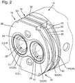
- Figure 2 shows an exemplary optical system 10 as it can be present in the distal end 6 of the endoscope shaft 4 of the endoscope 2.
- the optical system 10 is a stereoscopic system such as that in FIG Figure 2 shows schematically, simplified and perspective view.
- FIG. 2 shows an installation situation in which an endoscope tube normally surrounding the stereoscopic optical system 10 is omitted in order to reveal the components of the system.
- the stereoscopic optical system 10 includes a left optical channel 12 and a right optical channel 14. Of the optical components of the left optical channel 12 and the right optical channel 14 are shown in FIG Figure 2 the respective front lenses of the optical channels 12, 14 are shown by way of example.
- the stereoscopic optical system 10 further comprises an electromagnetic actuator 16, comprising a stator 18 and a rotor 20.
- the optical components of the left optical channel 12, for example those in FIG Figure 2 visible front lens is accommodated in a left guide tube 26. This relates to at least some of the optical components of the left optical channel 12.
- Optical components of the right optical channel 14 are arranged in a right guide tube 28 separate from the left guide tube 26.
- the two guide tubes 26, 28 are arranged, for example, parallel to one another. However, it is also provided that the guide tubes 26, 28 are arranged at an angle of, for example, 2 ° to one another, this angle generally not exceeding 5 °.
- the optical components of the right optical channel 14 arranged at least partially in the right guide tube 28.
- the guide tubes 26, 28 are, for example, separate components, for example tubes. It is also provided that the guide tubes 26, 28 are not separate components and instead are provided through bores let into a dumbbell-shaped component 64.
- the stator 18 is arranged outside the guide tubes 26, 28 and completely encloses the guide tubes 26, 28. This applies to a direction perpendicular to a longitudinal axial direction of the guide tubes 26, 28. In a longitudinal axial direction L, it is not necessary for the stator 18 to completely surround the guide tubes 26, 28.
- the runner 20 comprises a left runner 22 in which at least one optical component of the left optical channel 12 is received.
- the runner 20 further comprises a right runner 24 in which at least one optical component of the right optical channel 14 is received.
- the front lenses of the optical channels 12, 14 are each received in the corresponding runners 22, 24.
- the left rotor 22 is mounted displaceably in a left longitudinal axial direction LL along the left guide tube 26.
- the right runner 24 is mounted displaceably in the right guide tube 28 along a right longitudinal axial direction LR.
- the left longitudinal axial direction LL and the right longitudinal axial direction LR are aligned parallel to one another. They coincide with the central longitudinal axes of the respective guide tubes 26, 28. If it is not necessary in the following to differentiate between the left longitudinal axial direction LL and the right longitudinal axial direction LR, a general reference is made to a Reference is made to the longitudinal axial direction L, which extends parallel to the left and right longitudinal axial directions LL, LR.
- the left runner 22 and the right runner 24 each at least partially comprise a paramagnetic and / or ferromagnetic material.
- the rotors 22, 24 are made at least partially from a paramagnetic and / or a ferromagnetic material. It is thus possible to move the rotors 22, 24 by applying an electromagnetic field 68 in the respective longitudinal axial direction LL, LR in the associated guide tube 26, 28.
- the stator 18 comprises a distal permanent magnet 30 and a proximal permanent magnet 32.
- the two permanent magnets 30, 32 are polarized in opposite directions in the longitudinal axial direction L. Further details are provided in connection with the Figures 6 and 7th explained.
- stator 18 comprises an electrical coil for generating the electronic magnetic field 68.
- this coil is only partially visible.
- the electromagnetic field 68 generated by it serves to move the runners 22, 24 in their guide tubes 26, 28 along the respective longitudinal axial direction LL, LR.
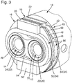
- Figure 3 shows that Figure 2 known stereoscopic optical system 10 also in a simplified perspective view and in an installation situation at a distal end 6 of an endoscope shaft 4. To reveal the components behind it, in particular the electrical coil 34 just mentioned, a proximal stator pole shoe is not shown.
- the stator 18 of the Figures 2 and 3 The stereoscopic optical system 10 shown comprises at its distal end 36 a distal stator pole shoe 38. At its in the longitudinal axial direction L opposite proximal end 40, the stator 18 comprises a proximal stator pole shoe 42.
- the stator 18 also comprises a central stator pole shoe 44, which is arranged in the longitudinal axial direction L between the permanent magnets 30, 32 and in the embodiment shown consists of a proximal central stator partial pole shoe 46 and is formed from a distal central part of the stator pole piece 48.
- an air gap 50 is present between the proximal central stator part pole piece 46 and the distal central stator part pole piece 48.
- the coil 34 is divided into a distal coil 52 and a proximal coil 54.
- the distal stator pole shoe 38, the distal coil 52, the distal permanent magnet 30 and the distal central stator part pole shoe 48 form a prefabricated distal assembly 60.
- the proximal central stator part pole shoe 46, the proximal coil 54, the proximal permanent magnet 32 and the proximal stator pole shoe 42 form a proximal assembly 62.
- the components of the distal assembly 60 are, for example, glued to one another. The same applies to the components of the proximal assembly 62. It is thus possible for prefabricated assemblies 60, 62 to be provided and for the stereoscopic optical system, more precisely its stator 18, to be assembled from these. In this context it is provided, for example, that the two assemblies 60, 62 are prefabricated identically.
- the only difference between the distal assembly 60 and the proximal assembly 62 is the polarity, ie the alignment, of their permanent magnets 30, 32.
- the polarity, ie the alignment, of their permanent magnets 30, 32 In order to provide an opposite orientation of the permanent magnets 30, 32 of the two assemblies 60, 62, one of the two assemblies 60, 62 rotated by 180 ° to the other assembly 60, 62 can be installed.
- the permanent magnets 30, 32 which are integrated into the assemblies 60, 62 are, for example, block-shaped magnets. These are also arranged, for example, in several groups, the groups preferably being arranged at mutually opposite positions. In the illustrated embodiment, the permanent magnets 30, 32 are arranged in two groups.
- the distal permanent magnet thus comprises the magnet block designated by reference numeral 30 and reference numeral 30 '.
- the proximal permanent magnet 32 comprises the block 32 present above in the longitudinal axial direction L proximally behind the distal permanent magnet 30 as well as a further magnet block 32 ', not visible in the figures, which is located in the longitudinal axial direction L proximally behind the distal permanent magnet block 30'.
- the permanent magnets 30, 32 are polarized in opposite directions in the longitudinal axial direction L.
- This repulsive force ensures that the distal assembly 60 and the proximal assembly 62 are pressed apart so that the air gap 50 remains between them.
- the distal assembly 60 is pressed against a distal stop, while the proximal assembly 62 is pressed against a proximal stop.
- the modules 60, 62 are advantageously aligned without the position reached being dependent on component tolerances.
- the groups of block-shaped permanent magnets are each on a flat side of an arrangement formed from the right and left guide tubes 26, 28. This shows Figure 3 especially clear.
- the left guide tube 26 and the right guide tube 28 are accommodated in a common component 64.
- the left guide gate 26 and / or the right guide tube 28 can be separate components, for example tubes. However, it is also provided that the left guide tube 26 and / or the right guide tube 28 are let into the common component 64 as bores.
- This common component 64 has a dumbbell-shaped cross section in a plane transverse to the longitudinal axial direction L.
- An inner contour of the pole shoes 38, 48, 46, 42 corresponds to an outer contour of the dumbbell-shaped component 64.
- An outer contour of the pole shoes 38, 48, 46, 42 is at least partially in the shape of a segment of a circle. How Figure 2 and 3 show, these sections of the pole shoes 38, 48, 46, 42 are located on the end faces of the arrangement formed from the left and right guide tubes 26, 28 and not on its flat sides.
- the coil 34 i. H. the distal coil 52 and the proximal coil 54 surround the left and right guide tubes 26, 28 and are oval in a plane located transversely to the longitudinal axial direction L.
- the permanent magnets 30, 32 are arranged on an outer side 66 of the coil 34 facing away from the guide tubes 26, 28. More precisely, the distal permanent magnet 30, 30 ′ is arranged on an outer side 66 of the distal coil 52 and a proximal permanent magnet 32 is arranged on the outer side 66 of a proximal coil 54.
- the permanent magnets 30, 32 form due to their arrangement magnetic return elements for the electrical Coil 34 generated electromagnetic field 68.
- the permanent magnets 30, 30 ', 32, 32' or even just one of these permanent magnets are made from a plastic matrix in which magnetic particles, in particular hard magnetic particles, are embedded.
- a permanent magnet can in particular be produced in an injection molding process.
- the permanent magnet 30, 30 ', 32, 32' not only can the permanent magnet itself be produced, but the components of the corresponding assembly 60, 62 can also be connected to one another. It is also advantageous if a coil wire of the coil 34 is passed through the permanent magnet 30, 30 ', 32, 32', that is to say, in other words, the coil wire is also cast in.
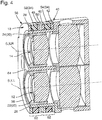
- Figure 4 shows the stereoscopic optical system 10 in a schematically simplified sectional view in a plane in which a connecting line between the two optical channels 12, 14 lies.
- the longitudinal axial directions LL, LR of the left optical channel 12 and of the right optical channel 14 also lie in this plane.
- Figure 5 shows a further schematic sectional view in a plane which is perpendicular to the plane in which the in Figure 4 shown sectional view lies.
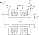
- Figure 6 shows the electromagnetic actuator 16 in de-energized State in which its runner, which is only intended to be the left runner 22 by way of example, is in a proximal end position.
- the rotor 22 is accommodated within the left guide tube 26 such that it can be displaced in the longitudinal axial direction L.
- the stator 18 of the electromagnetic actuator 16 Outside the guide tube 26 is the stator 18 of the electromagnetic actuator 16.
- the distal permanent magnet 30 and the proximal permanent magnet 32 which are polarized in opposite directions.
- the north-south directions of the permanent magnets 30, 32 are parallel to the longitudinal axial direction L.
- a distal stator pole shoe 38 is located at a distal end 36 of the stator 18, and a proximal stator pole shoe 42 is located at a proximal end 40 of the stator 18.
- a central stator pole piece 44 is located between the permanent magnets 30, 32.
- the coil 34 comprises a distal coil 52 and a proximal coil 54.
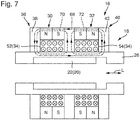
- Figure 7 shows the electromagnetic actuator 16, the distal coil 52 and the proximal coil 54 being energized.
- the two coils 52, 54 are coupled to one another in such a way that a first magnetic field generated by the respective coil 52, 54 and a second magnetic field are oriented in the same way. This results from the same energization of the two coils 52, 54.
- the direction of current flow is indicated in the schematically sketched conductors of the coils 52, 54.
- a current direction pointing out of the plane of the drawing is indicated by a point and a direction of current directed into the plane of the drawing is indicated by a cross.
- the first and second magnetic fields of the coils 52, 54 add up to the electromagnetic field 68, which is shown in dash-dotted line.
- the electromagnetic field 68 superimposes a first static magnetic field 70, which is generated by the distal permanent magnet 30, and a second static magnetic field 72, which is generated by the second permanent magnet 32 is generated.
- the electromagnetic field 68 and the first static magnetic field 70 are constructively superimposed so that the energization of the coil 34 on this side of the stator 18 increases the overall magnetic field.
- the electromagnetic field 68 and the second static magnetic field 72 which is generated by the proximal permanent magnet 32, are directed in opposite directions, so that at this end of the stator 18 there is a weakening of the total magnetic field.
Description
Die Erfindung betrifft ein stereoskopisches optisches System eines chirurgischen Instruments, umfassend einen linken optischen Kanal, einen rechten optischen Kanal und einen elektromagnetischen Aktuator mit einem Stator und einem Läufer. Ferner betrifft die Erfindung ein chirurgisches Instrument sowie ein Verfahren zum Herstellen eines stereoskopischen optischen Systems eines chirurgischen Instruments, mit einem linken optischen Kanal, einem rechten optischen Kanal und einem elektromagnetischen Aktuator mit einem Stator und einem Läufer.The invention relates to a stereoscopic optical system of a surgical instrument, comprising a left optical channel, a right optical channel and an electromagnetic actuator with a stator and a rotor. The invention also relates to a surgical instrument and a method for producing a stereoscopic optical system of a surgical instrument, with a left optical channel, a right optical channel and an electromagnetic actuator with a stator and a rotor.
Elektromagnetische Aktuatoren haben vielfältige Anwendungen. Beispielsweise können mit ihnen Schalter betätigt oder Mikrooptiken eingestellt oder verstellt werden. Bei chirurgischen Instrumenten, beispielsweise Endoskopen, können diese kleinbauenden Aktuatoren dazu verwendet werden, um einen Fokus oder eine Vergrößerung eines optischen Systems zu verändern. Bei Endoskopen mit variabler Blickrichtung ist es außerdem möglich, mithilfe eines elektromagnetischen Aktuators eine Blickrichtung des optischen Systems einzustellen oder zu verändern. Die Veränderung der optischen Eigenschaften eines optischen Systems erfolgt, indem ein optisches Bauteil, beispielsweise eine Linse, ein Prisma oder eine Blende, durch den Aktuator verschoben wird, wobei sich das optische Bauteil im oder am Läufer des Aktuators befindet.Electromagnetic actuators have a wide variety of uses. For example, they can be used to operate switches or set or adjust micro-optics. In the case of surgical instruments, for example endoscopes, these compact actuators can be used to change a focus or a magnification of an optical system. For endoscopes with With a variable viewing direction, it is also possible to set or change a viewing direction of the optical system with the aid of an electromagnetic actuator. The change in the optical properties of an optical system takes place in that an optical component, for example a lens, a prism or a diaphragm, is displaced through the actuator, the optical component being located in or on the runner of the actuator.
Es sind bistabile und monostabile elektromagnetische Aktuatoren bekannt. Bei einem bistabilen elektromagnetischen Aktuator ist ein Läufer vorhanden, der in einem Permanentmagnetfeld in einer von zwei extremen Positionen (Endpositionen) gehalten wird und durch Schaltung eines elektromagnetischen Felds aus einer dieser beiden stabilen Position in die jeweils andere stabile Position überführt werden kann. Bei einem monostabilen elektromagnetischen Aktuator wird der Läufer von einem Magnetfeld, welches von einem oder mehreren Permanentmagneten erzeugt wird, stabil in seiner Ruheposition gehalten. Durch Anlegen eines von einer Magnetspule erzeugten elektromagnetischen Felds wird der Läufer aus dieser stabilen Ruheposition heraus bewegt. Bistabile Systeme sind für einen zweistufigen Betrieb mit leistunglos gehaltenen Endpositionen besonders geeignet. Monostabile Systeme sind hingegen für eine kontinuierliche Verstellung gut geeignet.There are known bistable and monostable electromagnetic actuators. A bistable electromagnetic actuator has a rotor that is held in a permanent magnetic field in one of two extreme positions (end positions) and can be transferred from one of these two stable positions to the other stable position by switching an electromagnetic field. In the case of a monostable electromagnetic actuator, the rotor is held in a stable position in its rest position by a magnetic field which is generated by one or more permanent magnets. By applying an electromagnetic field generated by a magnetic coil, the rotor is moved out of this stable position of rest. Bistable systems are particularly suitable for two-stage operation with end positions held without power. Monostable systems, on the other hand, are well suited for continuous adjustment.
Wie bereits erwähnt, können elektromagnetische Aktuatoren zur Einstellung oder Verstellung eines optischen Systems eines chirurgischen Instruments eingesetzt werden. Das optische System eines Stereo-Endoskops umfasst zwei Objektive, die idealerweise simultan zueinander eingestellt oder fokussiert werden. Zu diesem Zweck wäre es möglich, zwei separate elektromagnetische Aktuatoren einzusetzen, wie sie ansonsten zur Verstellung einer einzelnen Optik eingesetzt werden. Dies ist jedoch mit hohen Kosten verbunden.As already mentioned, electromagnetic actuators can be used to set or adjust an optical system of a surgical instrument. The optical system of a stereo endoscope comprises two objectives that are ideally adjusted or focused simultaneously with one another. For this purpose, it would be possible to use two separate electromagnetic actuators, as they are otherwise used to adjust a single lens. However, this is associated with high costs.
Außerdem ist es wünschenswert, wenn die optischen Achsen der beiden Objektive, die für die stereoskopische Abbildung eingesetzt werden, einen möglichst großen Abstand, den sogenannten Stereoabstand, zueinander einhalten. Ein großer Stereoabstand ermöglicht einen guten 3-D Effekt. Gleichzeitig ist eine lichtstarke Optik wünschenswert, so dass nach Möglichkeit Objektive mit einem möglichst großen Durchmesser verwendet werden sollen. Je größer die Optikelemente werden, desto kleiner wird die freie Distanz zwischen den Objektiven. Soll der Stereoabstand konstant gehalten werden, so nimmt der Durchmesser eines die beiden Objektive umgebenden Rohres zu. Außerdem müssen die elektromagnetischen Aktuatoren untergebracht werden. Die genannten Forderungen stehen also mehr oder weniger in unmittelbarem Widerspruch zu dem im Rohr des Endoskops vorhandenen beschränkten Bauraum.It is also desirable if the optical axes of the two objectives that are used for stereoscopic imaging maintain the greatest possible distance, the so-called stereo distance, from one another. A large stereo distance enables a good 3-D effect. At the same time, a bright optical system is desirable, so that, if possible, objectives with the largest possible diameter should be used. The larger the optical elements, the smaller the free distance between the lenses. If the stereo distance is to be kept constant, the diameter of a tube surrounding the two objectives increases. In addition, the electromagnetic actuators must be accommodated. The requirements mentioned are therefore more or less in direct contradiction to the limited installation space available in the tube of the endoscope.
Aus
Es ist eine Aufgabe der Erfindung ein stereoskopisches optisches System, ein chirurgisches Instrument mit einem stereoskopischen optischen System sowie ein Verfahren zum Herstellen eines stereooptischen optischen Systems anzugeben, welches im Hinblick auf die im Stand der Technik vorhandenen Nachteile verbessert ist, also insbesondere eine kompakte Bauform aufweist.It is an object of the invention to specify a stereoscopic optical system, a surgical instrument with a stereoscopic optical system and a method for producing a stereo-optical system which is improved with regard to the disadvantages present in the prior art, i.e. in particular has a compact design .
Die Aufgabe wird gelöst durch ein stereoskopisches optisches System eines chirurgischen Instruments, umfassend einen linken optischen Kanal, einen rechten optischen Kanal und einen elektromagnetischen Aktuator mit einem Stator und einem Läufer, wobei das stereoskopische optische System dadurch fortgebildet ist, dass optische Komponenten des linken optischen Kanals in einem linken Führungsrohr und optische Komponenten des rechten optischen Kanals in einem separaten rechten Führungsrohr angeordnet sind, wobei der Stator außerhalb der Führungsrohre angeordnet ist und der Läufer einen linken Läufer, in dem zumindest eine optische Komponente des linken optischen Kanals aufgenommen ist, und einen rechten Läufer, in dem zumindest eine optische Komponente des rechten optischen Kanals aufgenommen ist, umfasst, und wobei der linke und der rechte Läufer in einer Längsaxialrichtung des linken und rechten Führungsrohrs in dem jeweiligen Führungsrohr verschiebbar gelagert sind, wobei die Läufer jeweils wenigstens teilweise ein paramagnetisches und/oder ferromagnetisches Material umfassen und durch Beaufschlagung mit einem elektromagnetischen Feld in der Längsaxialrichtung verschiebbar sind, wobei der Stator einen distalen Permanentmagneten und einen proximalen Permanentmagneten umfasst, die in Längsaxialrichtung gegensinnig gepolt sind, und wobei der Stator eine elektrische Spule zum Erzeugen des elektromagnetischen Felds umfasst.The object is achieved by a stereoscopic optical system of a surgical instrument, comprising a left optical channel, a right optical channel and an electromagnetic actuator with a stator and a rotor, the stereoscopic optical system being developed in that optical components of the left optical channel are arranged in a left guide tube and optical components of the right optical channel in a separate right guide tube, the stator being arranged outside the guide tubes and the runner being a left runner in which at least one optical Component of the left optical channel is received, and a right runner in which at least one optical component of the right optical channel is received, and wherein the left and right runners are slidably mounted in a longitudinal axial direction of the left and right guide tubes in the respective guide tube are, the rotors each at least partially comprise a paramagnetic and / or ferromagnetic material and are displaceable in the longitudinal axial direction by exposure to an electromagnetic field, the stator comprising a distal permanent magnet and a proximal permanent magnet, which are polarized in opposite directions in the longitudinal axial direction, and wherein the stator comprises an electrical coil for generating the electromagnetic field.
Das linke und das rechte Führungsrohr sind insbesondere parallel zueinander ausgerichtet, was bedeutet, dass eine Längsaxialrichtung des linken Führungsrohrs parallel zu einer Längsaxialrichtung des rechten Führungsrohrs orientiert ist. Sofern nicht zwischen dem linken und dem rechten Führungsrohr unterschieden werden muss, wird im Folgenden auch allgemein auf eine Längsaxialrichtung Bezug genommen, die in gleicher Richtung wie die Längsaxialrichtungen des linken und rechten Führungsrohrs orientiert ist. Es ist jedoch ebenso vorgesehen, dass das linke und das rechte Führungsrohr einen Winkel von beispielsweise 2° einschließen. Ferner insbesondere ist dieser Winkel zwischen der Längsaxialrichtung des linken Führungsrohrs und der Längsaxialrichtung des rechten Führungsrohrs kleiner als 5°. Wird auf lediglich eine Längsaxialrichtung Bezug genommen und schließen das linke und das rechte Führungsrohr einen Winkel ein, so liegt diese Längsaxialrichtung in der Mitte zwischen der Längsaxialrichtung des linken Führungsrohrs und der Längsaxialrichtung des rechten Führungsrohrs.The left and right guide tubes are in particular oriented parallel to one another, which means that a longitudinal axial direction of the left guide tube is oriented parallel to a longitudinal axial direction of the right guide tube. Unless a distinction has to be made between the left and the right guide tube, reference is also generally made below to a longitudinal axial direction which is oriented in the same direction as the longitudinal axial directions of the left and right guide tubes. However, it is also provided that the left and right guide tubes enclose an angle of, for example, 2 °. Furthermore, in particular, this angle between the longitudinal axial direction of the left guide tube and the longitudinal axial direction of the right guide tube is less than 5 °. If only one longitudinal axial direction is referred to and the left and right guide tubes enclose an angle, this longitudinal axial direction lies in the middle between the longitudinal axial direction of the left guide tube and the longitudinal axial direction of the right guide tube.
Das stereoskopische optische System gemäß Aspekten der Erfindung ist besonders vorteilhaft, da der rechte Läufer und der linke Läufer mithilfe eines einzigen und gemeinsamen elektromagnetischen Aktuators betätigt werden. Eine solche Konstruktion ist technisch einfach und außerdem kostengünstig zu realisieren. Sie nimmt außerdem lediglich einen sehr geringen Bauraum in Anspruch.The stereoscopic optical system according to aspects of the invention is particularly advantageous since the right runner and the left runner are actuated with the aid of a single and common electromagnetic actuator. Such a construction is technically simple and also inexpensive to implement. In addition, it only takes up very little space.
Der Einsatz separater Führungsrohre für den linken optischen Kanal und den rechten optischen Kanal ist auch aus den folgenden Gründen vorteilhaft. Es wäre denkbar, einen gemeinsamen Halter für beide optische Kanäle bzw. deren optische Komponenten vorzusehen. Ein solcher Halter müsste jedoch bezüglich Rotation um seine Längsaxialrichtung gesichert bzw. fixiert werden. Nur so könnte eine nachträgliche Verdrehung der Optik gegenüber den übrigen optischen Komponenten des stereoskopischen optischen Systems, beispielsweise der Bildsensoren, zuverlässig vermieden werden. Dies wäre beispielsweise durch Einsatz einer Passfeder möglich. Eine solche Lösung bringt jedoch wiederum neue technische Herausforderungen mit sich. Beispielsweise wäre eine Spielpassung erforderlich, um die gewünschte axiale Verschiebbarkeit zu ermöglichen. Auch die Verwendung eines Halters mit ovalem Querschnitt wäre möglich, der in einer passenden ovalen Bohrung eines Gleitrohres abgleitet. Der Nachteil einer solchen Konstruktion wäre jedoch, dass Bauteile mit ovalem Querschnitt stets aufwendig und weniger präzise zu fertigen sind.The use of separate guide tubes for the left optical channel and the right optical channel is also advantageous for the following reasons. It would be conceivable to provide a common holder for both optical channels or their optical components. However, such a holder would have to be secured or fixed with respect to rotation about its longitudinal axial direction. This is the only way to reliably avoid subsequent rotation of the optics with respect to the other optical components of the stereoscopic optical system, for example the image sensors. This would be possible, for example, by using a feather key. However, such a solution in turn brings with it new technical challenges. For example, a clearance fit would be required to enable the desired axial displaceability. It would also be possible to use a holder with an oval cross-section, which slides in a matching oval bore in a sliding tube. The disadvantage of such a construction, however, would be that components with an oval cross-section are always complex and less precise to manufacture.
Vor diesem Hintergrund hat es sich als vorteilhaft herausgestellt, je ein separates Führungsrohr für den linken Läufer und den rechten Läufer vorzusehen. Insbesondere sind die Führungsrohre im Querschnitt kreisrund.Against this background, it has been found to be advantageous to provide a separate guide tube each for the left runner and the right runner. In particular, the guide tubes are circular in cross section.
Gemäß einer vorteilhaften Ausführungsform ist das stereoskopische optische System dadurch fortgebildet, dass ein distales Ende des Stators von einem distalen Statorpolschuh und ein in Längsaxialrichtung gegenüberliegendes proximales Ende von einem proximalen Statorpolschuh gebildet sind. Ferner ist insbesondere vorgesehen, dass der Stator außerdem einen zentralen Statorpolschuh umfasst, der in Längsaxialrichtung zwischen den Permanentmagneten angeordnet ist. Vorteilhaft ist ferner vorgesehen, dass der zentrale Statorpolschuh aus einem proximalen zentralen Stator-Teil-Polschuh und aus einem distalen zentralen Stator-Teil-Polschuh gebildet ist. Insbesondere ist zwischen dem distalen zentralen Stator-Teil-Polschuh und dem proximalen zentralen Stator-Teil-Polschuh ein Luftspalt vorhanden.According to an advantageous embodiment, this is stereoscopic optical system in that a distal end of the stator is formed by a distal stator pole piece and a proximal end opposite in the longitudinal axial direction is formed by a proximal stator pole piece. Furthermore, it is provided in particular that the stator also comprises a central stator pole shoe, which is arranged in the longitudinal axial direction between the permanent magnets. It is also advantageously provided that the central stator pole shoe is formed from a proximal central stator part pole shoe and a distal central stator part pole shoe. In particular, there is an air gap between the distal central stator partial pole shoe and the proximal central stator partial pole shoe.
Ferner ist insbesondere vorgesehen, dass die Spule eine distale Spule und eine proximale Spule umfasst, wobei der distale Statorpolschuh, eine distale Spule, der distale Permanentmagnet und der distale zentrale Stator-Teil-Polschuh eine vorgefertigte distale Baugruppe bilden und der proximale zentrale Stator-Teil-Polschuh, eine proximale Spule, der proximale Permanentmagnet und der proximale Statorpolschuh eine vorgefertigte proximale Baugruppe bilden, wobei insbesondere die Bauteile der distalen und/oder der proximalen Baugruppe miteinander verklebt sind.Furthermore, it is particularly provided that the coil comprises a distal coil and a proximal coil, the distal stator pole piece, a distal coil, the distal permanent magnet and the distal central stator part pole shoe forming a prefabricated distal assembly and the proximal central stator part Pole shoe, a proximal coil, the proximal permanent magnet and the proximal stator pole shoe form a prefabricated proximal assembly, in particular the components of the distal and / or the proximal assembly being glued to one another.
Die Verwendung von Statorpolschuhen erlaubt die Erhöhung des Wirkungsgrads des elektromagnetischen Aktuators durch eine verbesserte magnetische Flussführung. In der Folge können vorteilhaft größere Haltekräfte bereitgestellt oder geringere Stellströme eingesetzt werden. Der zentrale Statorpolschuh ist insbesondere dicker als die äußeren Statorpolschuhe, d. h. der distale Statorpolschuh oder der proximale Statorpolschuh. Beispielsweise weist der zentrale Statorpolschuh eine Materialstärke, gemessen in Längsaxialrichtung, auf, welche 1,2-fach bis doppelt so groß ist wie die in gleicher Richtung gemessene Materialstärke der äußeren Polschuhe.The use of stator pole shoes allows the efficiency of the electromagnetic actuator to be increased through improved magnetic flux guidance. As a result, greater holding forces can advantageously be provided or lower control currents can be used. The central stator pole shoe is in particular thicker than the outer stator pole shoe, ie the distal stator pole shoe or the proximal stator pole shoe. For example, the central stator pole shoe has a material thickness, measured in the longitudinal axial direction, which is 1.2 times to twice as large as that in the same Material thickness of the outer pole pieces measured in the direction.
Der Luftspalt zwischen dem distalen zentralen Stator-Teil-Polschuh und dem proximalen zentralen Stator-Teil-Polschuh erlaubt es, eine distale und eine proximale Baugruppe zu bilden, die nicht mechanisch miteinander verbunden sind. Da sich die Permanentmagneten der beiden Baugruppen aufgrund ihrer gegensinnigen Orientierung gegenseitig abstoßen, richten sich die beiden Baugruppen selbstständig und unabhängig von gegebenenfalls vorhandenen Bauteiltoleranzen an einem distalen und einem proximalen Anschlag aus. Vorteilhaft kann auf die Verwendung eines Klebstoffs zur Verbindung der beiden Baugruppen verzichtet werden. Soll dennoch eine mechanische Verbindung der beiden Baugruppen hergestellt werden, so wird ein Klebstoff eingesetzt, der vorteilhaft eine besonders geringe Volumenschrumpfung während des Aushärtens zeigt. Geeignet ist beispielsweise ein Klebstoff, der während des Aushärtens weniger als 5 % Volumen einbüßt.The air gap between the distal central stator partial pole piece and the proximal central stator partial pole piece allows a distal and a proximal assembly to be formed which are not mechanically connected to one another. Since the permanent magnets of the two assemblies repel one another due to their opposing orientation, the two assemblies align themselves independently and independently of any component tolerances that may be present at a distal and a proximal stop. The use of an adhesive to connect the two assemblies can advantageously be dispensed with. If, however, a mechanical connection between the two assemblies is to be established, an adhesive is used which advantageously exhibits particularly low volume shrinkage during curing. For example, an adhesive that loses less than 5% volume during curing is suitable.
Es ist ferner insbesondere vorgesehen, dass die distale Baugruppe und die proximale Baugruppe identisch zueinander aufgebaut sind. Um die gegensätzliche magnetische Orientierung der Permanentmagnete in dem elektromagnetischen Aktuator zu realisieren, ist beim Zusammenbau vorgesehen, dass entweder die proximale Baugruppe oder die distale Baugruppe gegenüber der jeweils anderen Baugruppe um 180° gedreht eingebaut wird. Die Baugruppen werden passend verdrahtet, so dass diese gleich orientierte Magnetfelder erzeugen. Die Verwendung vorgefertigter Baugruppen beschleunigt die Herstellung des elektromagnetischen Aktuators.It is also provided in particular that the distal assembly and the proximal assembly are constructed identically to one another. In order to realize the opposing magnetic orientation of the permanent magnets in the electromagnetic actuator, it is provided during assembly that either the proximal assembly or the distal assembly is installed rotated by 180 ° with respect to the other assembly. The assemblies are wired appropriately so that they generate magnetic fields with the same orientation. The use of prefabricated assemblies accelerates the manufacture of the electromagnetic actuator.
Gemäß einer weiteren vorteilhaften Ausführungsform ist das stereoskopische optische System dadurch fortgebildet, dass das linke und das rechte Führungsrohr in einem gemeinsamen Bauteil aufgenommen sind, welches in einer Ebene quer zu der Längsaxialrichtung einen hantelförmigen Querschnitt aufweist und wobei eine Innenkontur der Polschuhe einer Außenkontur des hantelförmigen Bauteils entspricht und eine Außenkontur der Polschuhe zumindest abschnittsweise kreissegmentförmig ist.According to a further advantageous embodiment, the stereoscopic optical system is developed in that the left and right guide tubes are received in a common component which has a dumbbell-shaped cross section in a plane transverse to the longitudinal axial direction and wherein an inner contour of the pole pieces corresponds to an outer contour of the dumbbell-shaped component and an outer contour of the pole pieces is at least partially in the shape of a segment of a circle.
Vorteilhaft werden die beiden optischen Kanäle, d. h. die beiden Führungsrohre, in einem gemeinsamen Bauteil aufgenommen oder durch ein solches Bauteil bereitgestellt. Um einen hohen Wirkungsgrad des Aktuators zu erreichen ist es notwendig, dass die Statorpolschuhe so nah wie möglich am Läufer liegen. Beispielsweise ist vorgesehen, dass die Statorpolschuhe ebenfalls eine Geometrie aufweisen, in welche zwei Bohrungen zur Aufnahme der jeweiligen Aufnahmerohre eingebracht sind. Es ergibt sich bei einer solchen Konstruktion jedoch ein sehr schmaler Steg zwischen den beiden Bohrungen, mit den entsprechenden mechanischen Instabilitäten. Es hat sich aus diesem Grund als vorteilhaft herausgestellt, wenn das zentrale Bauteil, in welchem die beiden Aufnahmerohre aufgenommen sind, hantelförmig ausgeführt wird. Dabei reichen die Statorpolschuhe bis an die äußere Oberfläche dieses hantelförmigen Bauteils heran. So wird einerseits eine große mechanische Stabilität erreicht, was den Zusammenbau des Systems vereinfacht. Gleichzeitig sind die Statorpolschuhe ausreichend nah an den Läufern positioniert, so dass eine effiziente magnetische Flussführung gewährleistet werden kann.The two optical channels, d. H. the two guide tubes, received in a common component or provided by such a component. In order to achieve a high degree of efficiency of the actuator, it is necessary that the stator pole shoes are as close as possible to the rotor. For example, it is provided that the stator pole shoes also have a geometry in which two bores for receiving the respective receiving tubes are made. With such a construction, however, there is a very narrow web between the two bores, with the corresponding mechanical instabilities. For this reason, it has been found to be advantageous if the central component in which the two receiving tubes are received is designed in the shape of a dumbbell. The stator pole shoes reach up to the outer surface of this dumbbell-shaped component. In this way, on the one hand, great mechanical stability is achieved, which simplifies the assembly of the system. At the same time, the stator pole shoes are positioned sufficiently close to the rotors so that efficient magnetic flux guidance can be guaranteed.
Ferner ist insbesondere vorgesehen, dass sich die Statorpolschuhe in einer zu der Längsaxialrichtung senkrechten Radialrichtung von einer Außenseite des hantelförmigen Bauteils bis zu einer dem hantelförmigen Bauteil abgewandten Außenseite der Permanentmagneten und/oder bis zu einer dem hantelförmigen Bauteil abgewandten Außenseite der Magnetspulen erstrecken. Vorteilhaft wird durch eine solche Ausgestaltung die Flussführung verbessert.Furthermore, it is particularly provided that the stator pole shoes extend in a radial direction perpendicular to the longitudinal axial direction from an outside of the dumbbell-shaped component to an outside of the permanent magnets facing away from the dumbbell-shaped component and / or to an outside of the magnet coils facing away from the dumbbell-shaped component. Is advantageous through a such a configuration improves the flow management.
Gemäß einer weiteren Ausführungsform ist vorgesehen, dass die Spule eine distale Spule und eine proximale Spule umfasst, wobei sich die beiden Spulen in Längsaxialrichtung zu beiden Seiten des zentralen Statorpolschuhs erstrecken und elektrisch so miteinander gekoppelt sind, dass die distale Spule ein erstes Magnetfeld erzeugt, welches gleich zu einem von der proximalen Spule erzeugten zweiten Magnetfeld orientiert ist. Durch die Aufteilung der Magnetspule in eine erste Spule und eine zweite Spule kann diese in die vorgefertigte proximale Baugruppe und die vorgefertigte distale Baugruppe integriert werden.According to a further embodiment it is provided that the coil comprises a distal coil and a proximal coil, the two coils extending in the longitudinal axial direction on both sides of the central stator pole piece and being electrically coupled to one another in such a way that the distal coil generates a first magnetic field which is oriented equal to a second magnetic field generated by the proximal coil. By dividing the magnetic coil into a first coil and a second coil, it can be integrated into the prefabricated proximal assembly and the prefabricated distal assembly.
In einer weiteren vorteilhaften Ausführungsform ist das stereoskopische optische System dadurch fortgebildet, dass die Spule das linke und das rechte Führungsrohr umgibt und in einer quer zu der Längsaxialrichtung gelegenen Ebene oval ist. Die Spule hat beispielsweise die Form zweier Halbkreissegmente zwischen deren auf einer Seite liegenden Enden jeweils gerade Stücke eingefügt sind. Die Form der Spule entspricht also mit anderen Worten beispielsweise der Form einer Laufbahn. Eine solche Geometrie der Spule ist mit vertretbarem Aufwand zu wickeln und erlaubt trotzdem eine effiziente Einkopplung des magnetischen Flusses in die entscheidenden Bereiche des elektromagnetischen Aktuators. Die Form der Spule ist ferner insbesondere an eine Außenkontur der Führungsrohre angepasst. Es wäre möglich, einzelne Spulen für jeden optischen Kanal zu verwenden. Eine ovale Spule, die für beide Führungsrohre gemeinsam wirkt, stellt jedoch eine wesentlich kostengünstigere und außerdem platzsparende Lösung dar.In a further advantageous embodiment, the stereoscopic optical system is developed in that the coil surrounds the left and right guide tubes and is oval in a plane located transversely to the longitudinal axial direction. The coil has the shape of two semicircular segments, for example, between the ends of which straight pieces are inserted on one side. In other words, the shape of the coil corresponds, for example, to the shape of a raceway. Such a geometry of the coil can be wound with reasonable effort and nevertheless allows an efficient coupling of the magnetic flux into the critical areas of the electromagnetic actuator. The shape of the coil is also adapted in particular to an outer contour of the guide tubes. It would be possible to use individual coils for each optical channel. An oval coil that works together for both guide tubes, however, is a much more cost-effective and also space-saving solution.
Gemäß einer weiteren vorteilhaften Ausführungsform ist vorgesehen, dass die Permanentmagneten auf einer den Führungsrohren abgewandten Außenseite der Spule angeordnet sind. Eine solche Bauform ist besonders kompakt, da auf ein außenliegendes magnetisches Rückschlusselement verzichtet werden kann. Die Permanentmagneten wirken zumindest bereichsweise als magnetische Rückschlusselemente.According to a further advantageous embodiment it is provided that the permanent magnets on one of the guide tubes facing away from the outside of the coil are arranged. Such a design is particularly compact, since there is no need for an external magnetic return path element. The permanent magnets act at least in some areas as magnetic return path elements.
Ferner ist insbesondere vorgesehen, dass die Permanentmagneten blockförmige Magneten sind, die in zwei Gruppen angeordnet sind, wobei die Gruppen einander gegenüberliegend an je einer flachen Seite einer aus dem linken und rechten Führungsrohr gebildeten Anordnung angeordnet sind. An den flachen Seiten der neben einander liegenden Führungsrohren ist Bauraum vorhanden, da das Endoskoprohr, in dem die Einheit aufgenommen wird einen runden Innendurchmesser aufweist. Vorteilhaft ist es so möglich, die Optiken des rechten und linken Kanals möglichst weit voneinander entfernt zu positionieren, um so eine große Stereobasis zu realisieren. In dem verbleibenden Bauraum können die blockförmigen Permanentmagnete aufgenommen werden.Furthermore, it is provided in particular that the permanent magnets are block-shaped magnets which are arranged in two groups, the groups being arranged opposite one another on each flat side of an arrangement formed from the left and right guide tubes. There is installation space on the flat sides of the guide tubes lying next to one another, since the endoscope tube in which the unit is received has a round inner diameter. It is thus advantageously possible to position the optics of the right and left channels as far away from each other as possible in order to achieve a large stereo base. The block-shaped permanent magnets can be accommodated in the remaining installation space.
An den flachen Seiten der nebeneinander liegenden Rohre ist bei einer runden Aufnahmeöffnung freier Bauraum vorhanden. Diese flachen Seiten liegen zumindest näherungsweise parallel zu einem Abstand der beiden Rohre. An den senkrecht zu diesen flachen Seiten liegenden Stirnseiten, also in einer Ebene zumindest näherungsweise senkrecht zum Abstand zwischen den beiden Rohren, ist hingegen kein freier Bauraum vorhanden, da die beiden Rohre nebeneinander mit möglichst großem Abstand in der runden Aufnahmeöffnung platziert werden. Da die Spulen nur mit gleichmäßiger Wandstärke gewickelt werden können, ist es nicht möglich an diesen Stirnseiten der Anordnung Material der Spulen einzusparen. An den Stirnseiten kann jedoch auf Material des Stators und Material der Permanentmagnete verzichtet werden. Daher bietet sich die Nutzung der flachen Seiten zur Unterbringung der Permanentmagnete an. Es wäre möglich, Magnetscheiben zu verwenden, welche jedoch zumindest abschnittsweise eine sehr dünne Wandstärke aufweisen müssten. Da magnetisches Material ohnehin recht spröde ist, wäre die Handhabung derartiger Magnetscheiben beim Zusammenbau des stereoskopischen optischen Systems sehr schwierig. Magnetblöcke sind hingegen stabil und außerdem einfach und kostengünstig herzustellen. Ferner bewirkt die Anordnung der Magnete in dem genannten Bereich eine Kompensation der durch die Form der Statorpolschuhe beeinflussten magnetischen Flussführung.Free installation space is available on the flat sides of the tubes lying next to one another with a round receiving opening. These flat sides are at least approximately parallel to a distance between the two tubes. On the other hand, there is no free installation space on the end faces perpendicular to these flat sides, i.e. in a plane at least approximately perpendicular to the distance between the two tubes, since the two tubes are placed next to one another with the greatest possible spacing in the round receiving opening. Since the coils can only be wound with a uniform wall thickness, it is not possible to save material of the coils on these end faces of the arrangement. On the end faces, however, the material of the stator and the material of the permanent magnets can be dispensed with. Therefore the Use the flat sides to accommodate the permanent magnets. It would be possible to use magnetic disks which, however, would have to have a very thin wall thickness at least in sections. Since magnetic material is already quite brittle, the handling of such magnetic disks would be very difficult when assembling the stereoscopic optical system. Magnet blocks, on the other hand, are stable and also simple and inexpensive to manufacture. Furthermore, the arrangement of the magnets in the mentioned area compensates for the magnetic flux guidance influenced by the shape of the stator pole shoes.
Gemäß einer weiteren Ausführungsform ist vorgesehen, dass die Permanentmagneten magnetische Rückschlusselemente für das von der elektrischen Spule erzeugte Magnetfeld bilden. So kann vorteilhaft auf separate magnetische Rückschlusselemente verzichtet werden. Dies verringert die Bauform des elektromagnetischen Aktuators.According to a further embodiment it is provided that the permanent magnets form magnetic return elements for the magnetic field generated by the electrical coil. In this way, separate magnetic yoke elements can advantageously be dispensed with. This reduces the size of the electromagnetic actuator.
Gemäß einer weiteren vorteilhaften Ausführungsform ist das stereoskopische optische System dadurch fortgebildet, dass zumindest einer der Permanentmagnete hartmagnetische Partikel umfasst, die in einer Kunststoffmatrix eingebettet sind, wobei dieser Permanentmagnet insbesondere in einem Spritzgussverfahren hergestellt ist und ferner insbesondere in zumindest einem Permanentmagneten zumindest ein Spulendraht der Spule eingegossen ist. Als magnetische Partikel sind beispielsweise NdFeB-Partikel (Neodym, Eisen, Bohr) oder eine Mischung aus diesen Materialien geeignet, welche beispielsweise in einen Epoxidharzklebstoff eingerührt werden. Zur Herstellung der Permanentmagnete wird ein Freiraum zwischen den Statorpolschuhen ausgegossen. Dieser Freiraum wird anschließend von dem so hergestellten Permanentmagneten eingenommen. Vorteilhaft werden bei diesem Arbeitsgang nicht nur der Permanentmagnet selbst hergestellt sondern auch die Teile der Baugruppen miteinander verbunden bzw. vergossen. Anschließend ist beispielsweise vorgesehen, dass die so hergestellte Baugruppe aufmagnetisiert wird, so dass die magnetischen Partikel die gewünschte magnetische Orientierung einnehmen.According to a further advantageous embodiment, the stereoscopic optical system is further developed in that at least one of the permanent magnets comprises hard magnetic particles that are embedded in a plastic matrix, this permanent magnet being produced in particular in an injection molding process and furthermore in particular in at least one permanent magnet at least one coil wire of the coil is poured. NdFeB particles (neodymium, iron, Bohr) or a mixture of these materials, which are stirred into an epoxy resin adhesive, for example, are suitable as magnetic particles. To produce the permanent magnets, a free space is poured out between the stator pole shoes. This free space is then taken up by the permanent magnet produced in this way. It is not only the permanent magnet that is advantageous in this operation self-made but also the parts of the assemblies connected to one another or potted. It is then provided, for example, that the assembly produced in this way is magnetized so that the magnetic particles adopt the desired magnetic orientation.
Die Aufgabe wird außerdem gelöst durch ein chirurgisches Instrument, insbesondere Endoskop, mit einem stereoskopischen optischen System nach einem oder mehreren der zuvor genannten Ausführungsformen.The object is also achieved by a surgical instrument, in particular an endoscope, with a stereoscopic optical system according to one or more of the aforementioned embodiments.
Vorteilhaft kann das chirurgische Instrument ökonomisch und effizient hergestellt werden. Außerdem kann in einem solchen System eine große Stereobasis realisiert werden, was für die Abbildungseigenschaften eines chirurgischen Instruments, insbesondere eines Endoskops, besonders vorteilhaft ist. Im Übrigen treffen auf das chirurgische Instrument gleiche oder ähnliche Vorteile zu wie sie bereits im Hinblick auf das stereoskopische optische System selbst erwähnt wurden, so dass auf Wiederholungen verzichtet werden soll.The surgical instrument can advantageously be manufactured economically and efficiently. In addition, a large stereo base can be implemented in such a system, which is particularly advantageous for the imaging properties of a surgical instrument, in particular an endoscope. In addition, the same or similar advantages apply to the surgical instrument as were already mentioned with regard to the stereoscopic optical system itself, so that repetitions should be dispensed with.
Die Aufgabe wird außerdem gelöst durch ein Verfahren zum Herstellen eines stereoskopischen optischen Systems eines chirurgischen Instruments, mit einem linken optischen Kanal, einem rechten optischen Kanal und einem elektromagnetischen Aktuator mit einem Stator und einem Läufer, dadurch gekennzeichnet, dass optische Komponenten des linken optischen Kanals in einem linken Führungsrohr und optische Komponenten des rechten optischen Kanals in einem separaten rechten Führungsrohr angeordnet werden, wobei der Stator außerhalb der Führungsrohre angeordnet wird und der Läufer einen linken Läufer, in dem zumindest eine optische Komponente des linken optischen Kanals aufgenommen wird, und einen rechten Läufer, in dem zumindest eine optische Komponente des rechten optischen Kanals aufgenommen wird, umfasst, und wobei der linke und der rechte Läufer in einer Längsaxialrichtung des linken und rechten Führungsrohrs in dem jeweiligen Führungsrohr verschiebbar gelagert werden, wobei die Läufer jeweils wenigstens teilweise ein paramagnetisches und/oder ferromagnetisches Material umfassen und durch Beaufschlagung mit einem elektromagnetischen Feld in der Längsaxialrichtung verschiebbar sind, wobei im Stator ein distaler Permanentmagnet und ein proximaler Permanentmagnet derart angeordnet werden, dass sie in Längsaxialrichtung gegensinnig gepolt sind, und wobei im Stator eine elektrische Spule zum Erzeugen des elektromagnetischen Felds angeordnet wird.The object is also achieved by a method for producing a stereoscopic optical system of a surgical instrument, with a left optical channel, a right optical channel and an electromagnetic actuator with a stator and a runner, characterized in that optical components of the left optical channel in a left guide tube and optical components of the right optical channel are arranged in a separate right guide tube, the stator being arranged outside the guide tubes and the runner being a left runner in which at least one optical component of the left optical channel is accommodated, and a right runner, in which at least one optical component of the right optical channel is received, and wherein the left and the right runner are slidably mounted in a longitudinal axial direction of the left and right guide tube in the respective guide tube, the runner each at least partially comprise paramagnetic and / or ferromagnetic material and are displaceable in the longitudinal axial direction by exposure to an electromagnetic field, a distal permanent magnet and a proximal permanent magnet being arranged in the stator in such a way that they are polarized in opposite directions in the longitudinal axial direction, and in the stator an electrical coil for Generating the electromagnetic field is arranged.
Auch auf das Verfahren zum Herstellen eines stereoskopischen optischen Systems treffen gleiche oder ähnliche Vorteile zu wie sie bereits im Hinblick auf das stereoskopische optische System selbst erwähnt wurden.The same or similar advantages also apply to the method for producing a stereoscopic optical system as were already mentioned with regard to the stereoscopic optical system itself.
Gemäß einer vorteilhaften Ausführungsform ist das Verfahren dadurch fortgebildet, dass ein distales Ende des Stators von einem distalen Statorpolschuh und ein in Längsaxialrichtung gegenüberliegendes proximales Ende von einem proximalen Statorpolschuh gebildet sind und der Stator einen zentralen Statorpolschuh umfasst, der in Längsaxialrichtung zwischen den Permanentmagneten angeordnet wird und aus einem proximalen zentralen Stator-Teil-Polschuh und aus einem distalen zentralen Stator-Teil-Polschuh gebildet wird, wobei eine distale Baugruppe vorgefertigt wird, indem der distale Statorpolschuh, eine distale Spule, der distale Permanentmagnet und der distale zentrale Stator-Teil-Polschuh miteinander verklebt werden und eine proximale Baugruppe vorgefertigt wird, indem der proximale zentrale Stator-Teil-Polschuh, eine proximale Spule, der proximale Permanentmagnet und der proximale Statorpolschuh miteinander verklebt werden.According to an advantageous embodiment, the method is developed in that a distal end of the stator is formed by a distal stator pole shoe and a proximal end opposite in the longitudinal axial direction is formed by a proximal stator pole shoe and the stator comprises a central stator pole shoe which is arranged in the longitudinal axial direction between the permanent magnets and is formed from a proximal central stator partial pole piece and a distal central stator partial pole piece, a distal assembly being prefabricated by the distal stator pole piece, a distal coil, the distal permanent magnet and the distal central stator partial pole piece are glued together and a proximal assembly is prefabricated by the proximal central part of the stator pole piece, a proximal Coil, the proximal permanent magnet and the proximal stator pole piece are glued together.
Dabei ist insbesondere vorgesehen, dass die Permanentmagneten blockförmige Magneten sind, wobei die Magneten in zwei Gruppen angeordnet werden und die Gruppe einander gegenüberliegend an je einer flachen Seite einer aus dem linken und rechten Führungsrohr gebildeten Anordnung angeordnet werden.In particular, it is provided that the permanent magnets are block-shaped magnets, the magnets being arranged in two groups and the group being arranged opposite one another on each flat side of an arrangement formed from the left and right guide tubes.
Ferner ist das Verfahren gemäß einer weiteren Ausführungsform dadurch fortgebildet, dass zumindest einer der Permanentmagneten hergestellt wird, indem hartmagnetische Partikel in eine Kunststoffmatrix eingebettet werden, wobei dieser Permanentmagnet insbesondere in einem Spritzgussverfahren hergestellt wird und ferner insbesondere in zumindest einem Permanentmagneten zumindest ein Spulendraht der Spule eingegossen wird.Furthermore, according to a further embodiment, the method is developed in that at least one of the permanent magnets is produced by embedding hard magnetic particles in a plastic matrix, this permanent magnet being produced in particular in an injection molding process and furthermore, in particular, at least one coil wire of the coil being cast in at least one permanent magnet becomes.
Weitere Merkmale der Erfindung werden aus der Beschreibung erfindungsgemäßer Ausführungsformen zusammen mit den Ansprüchen und den beigefügten Zeichnungen ersichtlich. Erfindungsgemäße Ausführungsformen können einzelne Merkmale oder eine Kombination mehrerer Merkmale erfüllen.Further features of the invention will become apparent from the description of embodiments according to the invention together with the claims and the accompanying drawings. Embodiments according to the invention can fulfill individual features or a combination of several features.
Die Erfindung wird nachstehend ohne Beschränkung des allgemeinen Erfindungsgedankens anhand von Ausführungsbeispielen unter Bezugnahme auf die Zeichnungen beschrieben, wobei bezüglich aller im Text nicht näher erläuterten erfindungsgemäßen Einzelheiten ausdrücklich auf die Zeichnungen verwiesen wird. Es zeigen:
- Fig. 1
- ein Endoskop als beispielhaftes chirurgisches Instrument in einer schematisch vereinfachten Perspektivansicht,
- Fig. 2
- ein stereoskopisches optisches System in einer schematisch vereinfachten perspektivischen Ansicht,
- Fig. 3
- dieses System, wobei ein proximaler Statorpolschuh entfernt ist, um den Blick auf die dahinterliegenden Bauteile freizugeben,
- Fig. 4
- ein stereoskopisches optisches System in einer schematisch vereinfachten Schnittansicht in einer Ebene, in der eine Verbindungslinie der beiden optischen Kanäle liegt,
- Fig. 5
- eine weitere schematische Schnittansicht in einer Ebene, welche senkrecht zu derjenigen Ebene liegt, in der die in
Figur 4 - Fig. 6 und 7
- jeweils eine schematisch vereinfachte Prinzipskizze zur Erläuterung der Funktionsweise eines in einem stereoskopischen optischen System eingesetzten elektromagnetischen Aktuators.
- Fig. 1
- an endoscope as an exemplary surgical instrument in a schematically simplified perspective view,
- Fig. 2
- a stereoscopic optical system in a schematically simplified perspective view,
- Fig. 3
- this system, with a proximal stator pole piece removed to reveal the components behind it,
- Fig. 4
- a stereoscopic optical system in a schematically simplified sectional view in a plane in which a connecting line of the two optical channels lies,
- Fig. 5
- a further schematic sectional view in a plane which is perpendicular to the plane in which the in
Figure 4 shown sectional view is, - Figures 6 and 7
- each a schematically simplified basic sketch to explain the mode of operation of an electromagnetic actuator used in a stereoscopic optical system.
In den Zeichnungen sind jeweils gleiche oder gleichartige Elemente und/oder Teile mit denselben Bezugsziffern versehen, so dass von einer erneuten Vorstellung jeweils abgesehen wird.In the drawings, the same or similar elements and / or parts are provided with the same reference numerals, so that they are not introduced again in each case.
Der Stator 18 ist außerhalb der Führungsrohre 26, 28 angeordnet und umschließt die Führungsrohre 26, 28 vollständig. Dies gilt für eine zu einer Längsaxialrichtung der Führungsrohre 26, 28 senkrechte Richtung. In einer Längsaxialrichtung L ist es nicht erforderlich, dass der Stator 18 die Führungsrohre 26, 28 vollständig umschließt.The
Der Läufer 20 umfasst einen linken Läufer 22, in dem zumindest eine optische Komponente des linken optischen Kanals 12 aufgenommen ist. Ferner umfasst der Läufer 20 einen rechten Läufer 24, in dem zumindest eine optische Komponente des rechten optischen Kanals 14 aufgenommen ist. Im dargestellten Ausführungsbeispiel sind jeweils die Frontlinsen der optischen Kanäle 12, 14 in den entsprechenden Läufern 22, 24 aufgenommen.The
Der linke Läufer 22 ist in einer linken Längsaxialrichtung LL entlang des linken Führungsrohrs 26 verschiebbar gelagert. Der rechte Läufer 24 ist entlang einer rechten Längsaxialrichtung LR in dem rechten Führungsrohr 28 verschiebbar gelagert. Die linke Längsaxialrichtung LL und die rechte Längsaxialrichtung LR (jeweils mit strichpunktierter Linie angedeutet) sind parallel zueinander ausgerichtet. Sie fallen mit den Mittenlängsachsen der jeweiligen Führungsrohre 26, 28 zusammen. Sofern es im Folgenden nicht erforderlich ist, zwischen der linken Längsaxialrichtung LL und der rechten Längsaxialrichtung LR zu unterscheiden, wird allgemein auf eine Längsaxialrichtung L Bezug genommen, welche sich parallel zu der linken und der rechten Längsaxialrichtung LL, LR erstreckt.The
Der linke Läufer 22 und der rechte Läufer 24 umfassen jeweils wenigstens teilweise ein paramagnetisches und/oder ferromagnetisches Material. Mit anderen Worten sind also die Läufer 22, 24 zumindest teilweise aus einem paramagnetischen und/oder einem ferromagnetischen Material hergestellt. So ist es möglich, die Läufer 22, 24 durch Beaufschlagung mit einem elektromagnetischen Feld 68 in der jeweiligen Längsaxialrichtung LL, LR in dem zugehörigen Führungsrohr 26, 28 zu verschieben. Der Stator 18 umfasst einen distalen Permanentmagneten 30 und einen proximalen Permanentmagneten 32. Die beiden Permanentmagneten 30, 32 sind in Längsaxialrichtung L gegensinnig gepolt. Weitere Einzelheiten hierzu werden im Zusammenhang mit den
Ferner umfasst der Stator 18 eine elektrische Spule zum Erzeugen des elektronmagnetischen Felds 68. In
Der Stator 18 des in den
Der distale Statorpolschuh 38, die distale Spule 52, der distale Permanentmagnet 30 und der distale zentrale Stator-Teil-Polschuh 48 bilden eine vorgefertigte distale Baugruppe 60. Der proximale zentrale Stator-Teil-Polschuh 46, die proximale Spule 54, der proximale Permanentmagnet 32 und der proximale Statorpolschuh 42 bilden eine proximale Baugruppe 62. Die Bauteile der distalen Baugruppe 60 sind beispielsweise miteinander verklebt. Gleiches gilt für die Bauteile der proximalen Baugruppe 62. So ist es möglich, dass vorgefertigte Baugruppen 60, 62 bereitgestellt werden und aus diesen das stereoskopische optische System, genauer dessen Stator 18, zusammengesetzt wird. Es ist in diesem Zusammenhang beispielsweise vorgesehen, dass die beiden Baugruppen 60, 62 identisch vorgefertigt werden. Der Unterschied zwischen der distalen Baugruppe 60 und der proximalen Baugruppe 62 ist lediglich die Polung, d. h. die Ausrichtung, von deren Permanentmagneten 30, 32. Um eine entgegengesetzte Orientierung der Permanentmagnete 30, 32 der beiden Baugruppen 60, 62 bereitzustellen, kann eine der beiden Baugruppen 60, 62 um 180° gedreht zu der anderen Baugruppe 60, 62 eingebaut werden.The distal
Die Permanentmagneten 30, 32, welche in die Baugruppen 60, 62 integriert sind, sind beispielsweise blockförmige Magneten. Diese sind ferner beispielsweise in mehreren Gruppen angeordnet, wobei die Gruppen bevorzugt an einander gegenüberliegenden Positionen angeordnet sind. Im dargestellten Ausführungsbeispiel sind die Permanentmagneten 30, 32 in zwei Gruppen angeordnet. So umfasst der distale Permanentmagnet den mit Bezugszeichen 30 und Bezugszeichen 30' bezeichneten Magnetblock. Der proximale Permanentmagnet 32 umfasst den oberhalb in Längsaxialrichtung L proximal hinter dem distalen Permanentmagneten 30 vorhandenen Block 32 sowie einen weiteren, in den Figuren nicht sichtbaren, Magnetblock 32', der sich in Längsaxialrichtung L proximal hinter dem distalen Permanentmagnetblock 30' befindet. Die Permanentmagneten 30, 32 sind in Längsaxialrichtung L gegensinnig gepolt. Dies bedeutet, dass sich die Magnetblöcke gegenseitig abstoßen. Diese abstoßende Kraft sorgt dafür, dass die distale Baugruppe 60 und die proximale Baugruppe 62 auseinandergedrückt werden, so dass zwischen ihnen der Luftspalt 50 verbleibt. Die distale Baugruppe 60 wird an einen distalen Anschlag gedrückt, während die proximale Baugruppe 62 an einen proximalen Anschlag gedrückt wird. Vorteilhaft erfolgt die Ausrichtung der Baugruppen 60, 62 ohne dass die erreichte Position von Bauteiltoleranzen abhängig ist.The
Es ist nicht erforderlich, dass die beiden Baugruppen 60, 62 in der Einbausituation miteinander verbunden werden. Die zwischen den Baugruppen wirkenden abstoßenden Magnetkräfte sind groß genug, um die Baugruppen 60, 62 am Platz zu halten. Sollen die Baugruppen 60, 62 fixiert werden, so wird ein Klebstoff eingesetzt, der eine besonders geringe Volumenschrumpfung (beispielsweise weniger als 5 Vol.-%) während des Aushärtvorgangs zeigt.It is not necessary for the two
Die Gruppen der blockförmigen Permanentmagneten sind jeweils an einer flachen Seite einer aus dem rechten und linken Führungsrohr 26, 28 gebildeten Anordnung angeordnet. Dies zeigt
Das linke Führungsrohr 26 und das rechte Führungsrohr 28 sind in einem gemeinsamen Bauteil 64 aufgenommen. Wie bereits erwähnt, kann es sich bei dem linken Führungstor 26 und/oder dem rechten Führungsrohr 28 um separate Bauteile, beispielsweise Rohre, handeln. Es ist jedoch ebenso vorgesehen, dass das linke Führungsrohr 26 und/oder das rechte Führungsrohr 28 als Bohrungen in das gemeinsame Bauteil 64 eingelassen sind. Dieses gemeinsame Bauteil 64 weist in einer Ebene quer zu der Längsaxialrichtung L einen hantelförmigen Querschnitt auf. Eine Innenkontur der Polschuhe 38, 48, 46, 42 entspricht einer Außenkontur des hantelförmigen Bauteils 64. Eine Außenkontur der Polschuhe 38, 48, 46, 42 ist zumindest abschnittsweise kreissegmentförmig. Wie
Die Spule 34, d. h. die distale Spule 52 und die proximale Spule 54, umgeben das linke und rechte Führungsrohr 26, 28 und sind in einer quer zu der Längsaxialrichtung L gelegenen Ebene oval. Die Permanentmagneten 30, 32 sind auf einer den Führungsrohren 26, 28 abgewandten Außenseite 66 der Spule 34 angeordnet. Genauer gesagt ist der distale Permanentmagnet 30, 30' auf einer Außenseite 66 der distalen Spule 52 angeordnet und ein proximaler Permanentmagnet 32 ist auf der Außenseite 66 einer proximalen Spule 54 angeordnet.The
Die Permanentmagneten 30, 32 bilden aufgrund ihrer Anordnung magnetische Rückschlusselemente für das von der elektrischen Spule 34 erzeugte elektromagnetische Feld 68.The
Beispielsweise sind die Permanentmagneten 30, 30', 32, 32' oder auch nur einer dieser Permanentmagnete aus einer Kunststoffmatrix hergestellt, in die magnetische Partikel, insbesondere hartmagnetische Partikel, eingebettet sind. Ein solcher Permanentmagnet lässt sich insbesondere in einem Spritzgussverfahren herstellen. Vorteilhaft kann bei Herstellung des Permanentmagneten 30, 30', 32, 32' nicht nur der Permanentmagnet selbst hergestellt werden, sondern es können auch die Bauteile der entsprechenden Baugruppe 60, 62 miteinander verbunden werden. Es ist ferner vorteilhaft, wenn ein Spulendraht der Spule 34 durch den Permanentmagneten 30, 30', 32, 32' hindurchgeführt wird, also mit anderen Worten der Spulendraht mit eingegossen wird.For example, the
Die Funktionsweise des elektromagnetischen Aktuators des stereoskopischen optischen Systems 10 wird im Folgenden unter Bezugnahme auf die schematisch vereinfachten Prinzipskizzen der
Das elektromagnetische Feld 68 überlagert ein erstes statisches Magnetfeld 70, welches von dem distalen Permanentmagneten 30 erzeugt wird und ein zweites statisches Magnetfeld 72, welches von dem zweiten Permanentmagneten 32 erzeugt wird. Am distalen Ende 36 des Stators 18 überlagern sich das elektromagnetische Feld 68 und das erste statische Magnetfeld 70 konstruktiv, so dass durch die Bestromung der Spule 34 an dieser Seite des Stators 18 eine Verstärkung des insgesamt vorliegenden Magnetfelds eintritt. Am proximalen Ende 40 des Stators 18 sind das elektromagnetische Feld 68 und das zweite statische Magnetfeld 72, welches von dem proximalen Permanentmagneten 32 erzeugt wird, entgegengerichtet, so dass an diesem Ende des Stators 18 eine Abschwächung des in Summe vorliegenden Magnetfelds stattfindet. So wirkt in einem Spalt (der in der dargestellten Situation geschlossen ist) zwischen dem Läufer 22 und dem Führungsrohr 26 an dem distalen Ende 36 eine größere Kraft als am proximalen Ende 40, so dass sich der Läufer 20 in die in
In den
Die Erfindung ist in den folgenden Ansprüchen definiert.The invention is defined in the following claims.
- 22
- Endoskopendoscope
- 44th
- EndoskopschaftEndoscope shaft
- 66th
- distales Endedistal end
- 88th
- HandgriffHandle
- 1010
- stereoskopisches optisches Systemstereoscopic optical system
- 1212th
- linker optischer Kanalleft optical channel
- 1414th
- rechter optischer Kanalright optical channel
- 1616
- elektromagnetischer Aktuatorelectromagnetic actuator
- 1818th
- Statorstator
- 2020th
- Läuferrunner
- 2222nd
- linker Läuferleft runner
- 2424
- rechter Läuferright runner
- 2626th
- linkes Führungsrohrleft guide tube
- 2828
- rechtes Führungstorright lead gate
- 30, 30'30, 30 '
- distaler Permanentmagnetdistal permanent magnet
- 32, 32'32, 32 '
- proximaler Permanentmagnetproximal permanent magnet
- 3434
- SpuleKitchen sink
- 3636
- distales Ende des Statorsdistal end of the stator
- 3838
- distaler Statorpolschuhdistal stator pole piece
- 4040
- proximales Ende des Statorsproximal end of the stator
- 4242
- proximaler Statorpolschuhproximal stator pole piece
- 4444
- zentraler Statorpolschuhcentral stator pole piece
- 4646
- proximaler zentraler Stator-Teil-PolschuhProximal central part of the stator pole piece
- 4848
- distaler zentraler Stator-Teil-Polschuhdistal central stator part pole piece
- 5050
- LuftspaltAir gap
- 5252
- distale Spuledistal coil
- 5454
- proximale Spuleproximal coil
- 6060
- distale Baugruppedistal assembly
- 6262
- proximale Baugruppeproximal assembly
- 6464
- hantelförmiges Bauteildumbbell-shaped component
- 6666
- AußenseiteOutside
- 6868
- elektromagnetisches Feldelectromagnetic field
- 7070
- erstes statisches Magnetfeldfirst static magnetic field
- 7272
- zweites statisches Magnetfeldsecond static magnetic field
- LL.
- LängsaxialrichtungLongitudinal axial direction
- LLLL
- linke Längsaxialrichtungleft longitudinal axial direction
- LRLR
- rechte Längsaxialrichtungright longitudinal axial direction
Claims (14)
- A stereoscopic optical system (10) for a surgical instrument, the system comprising a left optical channel (12), a right optical channel (14) and an electromagnetic actuator (16) with a stator (18) and a rotor (20), wherein optical components of the left optical channel (12) are arranged in a left guide tube (26) and optical components of the right optical channel (14) are arranged in a separate right guide tube (28), wherein the rotor comprises a left rotor (22), in which at least one optical component of the left optical channel (12) is accommodated, and a right rotor (24), in which at least one optical component of the right optical channel (14) is accommodated, and wherein the left and the right rotor (22, 24) are mounted in the respective guide tube (26, 28) such that they can move in a longitudinal axial direction (LL, LR) of the left and right guide tube (26, 28), wherein the rotors (22, 24) each at least partially comprise a paramagnetic and/or ferromagnetic material and can be moved in the longitudinal axial direction (LL, LR) by application of an electromagnetic field (68), and wherein the stator (18) comprises an electric coil (34) for generating the electromagnet field; characterized in that
the stator (18) comprises a distal permanent magnet (30) and a proximal permanent magnet (32) which are oppositely polarized in the longitudinal axial direction (L); and wherein the stator is arranged outside the guide tubes. - The stereoscopic optical system (10) according to Claim 1, wherein a distal end (36) of the stator (18) is formed by a distal stator pole shoe (38) and an opposite proximal end (40) in the longitudinal axial direction (L) is formed by a proximal stator pole shoe (42), and the stator (18) in addition comprises a central stator pole shoe (44) which is arranged between the permanent magnets (30, 32) in the longitudinal axial direction (L), wherein the central stator pole shoe (44) is formed from a proximal central stator part pole shoe (46) and from a distal central stator part pole shoe (48).
- The stereoscopic optical system (10) according to Claim 2, wherein the coil (34) comprises a distal coil (52) and a proximal coil (54), wherein the distal stator pole shoe (38), the distal coil (52), the distal permanent magnet (30) and the distal central stator part pole shoe (48) form a prefabricated distal assembly (60) and the proximal central stator part pole shoe (46), the proximal coil (54), the proximal permanent magnet (32) and the proximal stator pole shoe (42) form a prefabricated proximal assembly (62), wherein the components of the distal and/or the proximal assembly (60, 62) are in particular bonded to one another.
- The stereoscopic optical system (10) according to Claim 2 or 3, wherein the left and the right guide tube (26, 28) are accommodated in a joint component (64) which has a dumbbell-shaped cross-section in a plane transversely to the longitudinal axial direction (L), and wherein an inner contour of the pole shoes (38, 48, 46, 42) corresponds to an outer contour of the dumbbell-shaped component (64) and an outer contour of the pole shoes (38, 48, 46, 42) is in the form of a circular segment at least in sections.
- The stereoscopic optical system (10) according to any one of Claims 1 to 4, wherein the coil (34) surrounds the left and the right guide tube (26, 28) and is oval in a plane oriented perpendicular to the longitudinal axial direction (L).
- The stereoscopic optical system (10) according to any one of Claims 1 to 5, wherein the permanent magnets (30, 32) are arranged on an outer side (66) of the coil (34) facing away from the guide tubes (26, 28).
- The stereoscopic optical system (10) according to any one of Claims 1 to 6, wherein the permanent magnets (30, 32) are block-shaped magnets which are arranged in two groups, wherein the groups are arranged opposite one another on a flat side each of an arrangement formed from the left and right guide tube (26, 28).
- The stereoscopic optical system (10) according to any one of Claims 1 to 7, wherein the permanent magnets (30, 32) form magnetic return elements for the magnetic field generated by the electric coil (34).
- The stereoscopic optical system (10) according to any one of Claims 1 to 8, wherein at least one of the permanent magnets (30, 30', 32, 32') comprises magnetically hard particles which are embedded in a plastic matrix, wherein said permanent magnet (30, 30', 32, 32') is in particular produced using an injection molding method and at least one coil wire of the coil (34) is additionally in particular molded in at least one permanent magnet.
- A surgical instrument, in particular an endoscope (2), having a stereoscopic optical system (10) according to any one of Claims 1 to 9.
- A method for producing a stereoscopic optical system (10) for a surgical instrument, having a left optical channel (12), a right optical channel (14) and an electromagnetic actuator (16) with a stator (18) and a rotor (20), characterized in that optical components of the left optical channel (12) are arranged in a left guide tube (26) and optical components of the right optical channel (14) are arranged in a separate right guide tube (28), wherein the stator (18) is arranged outside the guide tubes (26, 28) and the rotor (20) comprises a left rotor (22), in which at least one optical component of the left optical channel (12) is accommodated, and a right rotor (24), in which at least one optical component of the right optical channel (14) is accommodated, and wherein the left and the right rotor (22, 24) are mounted in the respective guide tube (26, 28) such that they can move in a longitudinal axial direction (L) of the left and right guide tube (26, 28), wherein the rotors (22, 24) each at least partially comprise a paramagnetic and/or ferromagnetic material and can be moved in the longitudinal axial direction (L) by application of an electromagnetic field (68), wherein a distal permanent magnet (30) and a proximal permanent magnet (32) are arranged in the stator (18) in such a way that they are oppositely polarized in the longitudinal axial direction (L), and wherein an electric coil (34) for generating the electromagnet field (68) is arranged in the stator (18).
- The method according to Claim 11, wherein a distal end (36) of the stator (18) is formed by a distal stator pole shoe (38) and an opposite proximal end (40) in the longitudinal axial direction (L) is formed by a proximal stator pole shoe (42), and the stator (18) comprises a central stator pole shoe (44) which is arranged between the permanent magnets (30, 32) in the longitudinal axial direction (L) and is formed from a proximal central stator part pole shoe (46) and from a distal central stator part pole shoe (48), wherein a distal assembly (60) is prefabricated in that the distal stator pole shoe (38), a distal coil (52), the distal permanent magnet (30) and the distal central stator part pole shoe (48) are bonded to one another and a proximal assembly (62) is prefabricated in that the proximal central stator part pole shoe (46), a proximal coil (54), the proximal permanent magnet (32) and the proximal stator pole shoe (42) are bonded to one another.
- The method according to Claim 11 or 12, wherein the permanent magnets (30, 32) are block-shaped magnets, wherein the magnets are arranged in two groups and the groups are arranged opposite one another on a flat side each of an arrangement formed from the left and right guide tube (26, 28).
- The method according to any one of Claims 11 to 13, wherein at least one of the permanent magnets (30, 32) is produced in that magnetically hard particles are embedded in a plastic matrix, wherein said permanent magnet is in particular produced using an injection molding method and at least one coil wire of the coil (34) is additionally in particular molded in at least one permanent magnet (30, 32).
Applications Claiming Priority (2)
| Application Number | Priority Date | Filing Date | Title |
|---|---|---|---|
| DE102017107414.7A DE102017107414A1 (en) | 2017-04-06 | 2017-04-06 | Stereoscopic optical system of a surgical instrument and method of making the same |
| PCT/EP2018/057351 WO2018184862A1 (en) | 2017-04-06 | 2018-03-22 | Stereoscopic optical system of a surgical instrument and method for producing same |
Publications (2)
| Publication Number | Publication Date |
|---|---|
| EP3606397A1 EP3606397A1 (en) | 2020-02-12 |
| EP3606397B1 true EP3606397B1 (en) | 2021-03-17 |
Family
ID=61965923
Family Applications (1)
| Application Number | Title | Priority Date | Filing Date |
|---|---|---|---|
| EP18717244.0A Active EP3606397B1 (en) | 2017-04-06 | 2018-03-22 | Stereoscopic optical system of a surgical instrument and method for producing same |
Country Status (6)
| Country | Link |
|---|---|
| US (1) | US11419485B2 (en) |
| EP (1) | EP3606397B1 (en) |
| JP (1) | JP2020516352A (en) |
| CN (1) | CN110475499A (en) |
| DE (1) | DE102017107414A1 (en) |
| WO (1) | WO2018184862A1 (en) |
Families Citing this family (1)
| Publication number | Priority date | Publication date | Assignee | Title |
|---|---|---|---|---|
| CN113907694B (en) * | 2021-12-14 | 2022-03-01 | 极限人工智能有限公司 | Binocular endoscope alignment method and alignment system |
Family Cites Families (13)
| Publication number | Priority date | Publication date | Assignee | Title |
|---|---|---|---|---|
| US3248499A (en) * | 1962-09-13 | 1966-04-26 | Digital Analog Technical Assoc | Electro-mechanical actuator with permanent magnet |
| CN102089680B (en) * | 2008-07-10 | 2016-08-17 | 皇家飞利浦电子股份有限公司 | Optical image probe |
| JP5834074B2 (en) * | 2010-07-05 | 2015-12-16 | オリンパス ビンテル ウント イーベーエー ゲーエムベーハーOlympus Winter & Ibe Gesellschaft Mit Beschrankter Haftung | Electromagnetic actuator for surgical instruments |
| DE102011089055A1 (en) * | 2011-12-19 | 2013-06-20 | Technische Universität Berlin | Instrument e.g. medical instrument e.g. endoscope for e.g. medical investigation, has actuator that is provided to adjust adjusting element along longitudinal axis of runner relative to stator and is designed as reluctance motor |
| CN202801550U (en) * | 2012-09-25 | 2013-03-20 | 天津博朗科技发展有限公司 | Double regulation device of three-dimensional endoscope |
| DE102012224179A1 (en) * | 2012-12-21 | 2014-06-26 | Olympus Winter & Ibe Gmbh | Electromagnetic actuator for a surgical instrument |
| DE102013202019A1 (en) * | 2013-02-07 | 2014-08-07 | Olympus Winter & Ibe Gmbh | Bistable electromagnetic actuator and surgical instrument |
| JP2014183644A (en) * | 2013-03-19 | 2014-09-29 | Olympus Corp | Electromagnetic actuator |
| JP6388361B2 (en) * | 2014-01-28 | 2018-09-12 | オリンパス株式会社 | Drive unit, optical unit, imaging device, and endoscope |
| DE102014103169A1 (en) * | 2014-03-10 | 2015-09-10 | Technische Universität Berlin | Optical device and optical system |
| DE102014204736A1 (en) * | 2014-03-14 | 2015-09-17 | Olympus Winter & Ibe Gmbh | Bistable electromagnetic actuator and surgical instrument |
| DE102014107297A1 (en) * | 2014-05-23 | 2015-11-26 | Karl Storz Gmbh & Co. Kg | Position controlled electrodynamic linear drive |
| DE102014214358B4 (en) * | 2014-07-23 | 2017-12-28 | Olympus Winter & Ibe Gmbh | Stereo video endoscope with multiple optical assemblies |
-
2017
- 2017-04-06 DE DE102017107414.7A patent/DE102017107414A1/en not_active Ceased
-
2018
- 2018-03-22 JP JP2019554727A patent/JP2020516352A/en active Pending
- 2018-03-22 EP EP18717244.0A patent/EP3606397B1/en active Active
- 2018-03-22 WO PCT/EP2018/057351 patent/WO2018184862A1/en unknown
- 2018-03-22 CN CN201880019864.4A patent/CN110475499A/en active Pending
-
2019
- 2019-09-26 US US16/583,849 patent/US11419485B2/en active Active
Non-Patent Citations (1)
| Title |
|---|
| None * |
Also Published As
| Publication number | Publication date |
|---|---|
| US11419485B2 (en) | 2022-08-23 |
| EP3606397A1 (en) | 2020-02-12 |
| WO2018184862A1 (en) | 2018-10-11 |
| CN110475499A (en) | 2019-11-19 |
| JP2020516352A (en) | 2020-06-11 |
| US20200022568A1 (en) | 2020-01-23 |
| DE102017107414A1 (en) | 2018-10-11 |
Similar Documents
| Publication | Publication Date | Title |
|---|---|---|
| EP2362530B1 (en) | Linear motor with permanent magnetic lock | |
| EP2591480B1 (en) | Electromagnetic actuator for a surgical instrument | |
| EP2034594B1 (en) | Electromagnetic linear motor | |
| EP2954542B1 (en) | Bi-stable electromagnetic actuator, and surgical instrument | |
| WO2014094972A1 (en) | Electromagnetic actuator for a surgical instrument | |
| WO2015135814A2 (en) | Bistable electromagnetic actuator and surgical instrument | |
| EP2175458A2 (en) | Linear motor for optical systems | |
| EP1609233A1 (en) | Gliding field linear motor | |
| DE102010000583A1 (en) | Reluctance and Lorentz-powered linear drive | |
| WO2019001623A1 (en) | Permanent magnet energized motor with rotatable bar magnets | |
| EP2947756B1 (en) | Position controlled electrodynamic linear motor | |
| EP3606397B1 (en) | Stereoscopic optical system of a surgical instrument and method for producing same | |
| EP3606396B1 (en) | Electromagnetic actuator for a surgical instrument and method for producing same | |
| DE102015120019A1 (en) | Gripper comprising coordinated movable gripping elements | |
| EP3487049B1 (en) | Linear motor comprising a transversal flux | |
| EP1604445B1 (en) | Magnetic linear drive | |
| DE10247228B4 (en) | Method and device for magnetizing a permanent magnet ring magnet with an even number of poles | |
| WO2018099783A1 (en) | Electromagnetic actuator for a surgical instrument | |
| DE102011089055A1 (en) | Instrument e.g. medical instrument e.g. endoscope for e.g. medical investigation, has actuator that is provided to adjust adjusting element along longitudinal axis of runner relative to stator and is designed as reluctance motor | |
| DE102018001243A1 (en) | Bistable electromagnetic lifting actuator and wire drawing machine | |
| DE102012104832A1 (en) | Hollow-cylindrical bistable reluctance actuator (BRA) used for medical video endoscope, has permanent magnet whose length is set to specific times the stroke of BRA, and coil whose length is not greater than the total length of the BRA | |
| DE102022101984A1 (en) | Process for manufacturing a rotor | |
| EP0644561A1 (en) | Magnet system for an electromagnetic actuator | |
| DE102016015758A1 (en) | Electric linear direct drive and linear guide | |
| EP2621055A1 (en) | Electric machine and rotor for an electric machine |
Legal Events
| Date | Code | Title | Description |
|---|---|---|---|
| STAA | Information on the status of an ep patent application or granted ep patent |
Free format text: STATUS: UNKNOWN |
|
| STAA | Information on the status of an ep patent application or granted ep patent |
Free format text: STATUS: THE INTERNATIONAL PUBLICATION HAS BEEN MADE |
|
| PUAI | Public reference made under article 153(3) epc to a published international application that has entered the european phase |
Free format text: ORIGINAL CODE: 0009012 |
|
| STAA | Information on the status of an ep patent application or granted ep patent |
Free format text: STATUS: REQUEST FOR EXAMINATION WAS MADE |
|
| 17P | Request for examination filed |
Effective date: 20190924 |
|
| AK | Designated contracting states |
Kind code of ref document: A1 Designated state(s): AL AT BE BG CH CY CZ DE DK EE ES FI FR GB GR HR HU IE IS IT LI LT LU LV MC MK MT NL NO PL PT RO RS SE SI SK SM TR |
|
| AX | Request for extension of the european patent |
Extension state: BA ME |
|
| DAV | Request for validation of the european patent (deleted) | ||
| DAX | Request for extension of the european patent (deleted) | ||
| GRAP | Despatch of communication of intention to grant a patent |
Free format text: ORIGINAL CODE: EPIDOSNIGR1 |
|
| STAA | Information on the status of an ep patent application or granted ep patent |
Free format text: STATUS: GRANT OF PATENT IS INTENDED |
|
| RIC1 | Information provided on ipc code assigned before grant |
Ipc: G02B 7/08 20060101ALI20201116BHEP Ipc: H02K 33/18 20060101ALI20201116BHEP Ipc: G02B 7/06 20060101ALI20201116BHEP Ipc: A61B 1/00 20060101AFI20201116BHEP Ipc: G02B 23/24 20060101ALI20201116BHEP Ipc: H01F 7/16 20060101ALI20201116BHEP |
|
| INTG | Intention to grant announced |
Effective date: 20201222 |
|
| GRAS | Grant fee paid |
Free format text: ORIGINAL CODE: EPIDOSNIGR3 |
|
| GRAA | (expected) grant |
Free format text: ORIGINAL CODE: 0009210 |
|
| STAA | Information on the status of an ep patent application or granted ep patent |
Free format text: STATUS: THE PATENT HAS BEEN GRANTED |
|
| AK | Designated contracting states |
Kind code of ref document: B1 Designated state(s): AL AT BE BG CH CY CZ DE DK EE ES FI FR GB GR HR HU IE IS IT LI LT LU LV MC MK MT NL NO PL PT RO RS SE SI SK SM TR |
|
| REG | Reference to a national code |
Ref country code: GB Ref legal event code: FG4D Free format text: NOT ENGLISH |
|
| REG | Reference to a national code |
Ref country code: CH Ref legal event code: EP |
|
| REG | Reference to a national code |
Ref country code: DE Ref legal event code: R096 Ref document number: 502018004367 Country of ref document: DE |
|
| REG | Reference to a national code |
Ref country code: IE Ref legal event code: FG4D Free format text: LANGUAGE OF EP DOCUMENT: GERMAN |
|
| REG | Reference to a national code |
Ref country code: AT Ref legal event code: REF Ref document number: 1371439 Country of ref document: AT Kind code of ref document: T Effective date: 20210415 |
|
| REG | Reference to a national code |
Ref country code: LT Ref legal event code: MG9D |
|
| PG25 | Lapsed in a contracting state [announced via postgrant information from national office to epo] |
Ref country code: FI Free format text: LAPSE BECAUSE OF FAILURE TO SUBMIT A TRANSLATION OF THE DESCRIPTION OR TO PAY THE FEE WITHIN THE PRESCRIBED TIME-LIMIT Effective date: 20210317 Ref country code: HR Free format text: LAPSE BECAUSE OF FAILURE TO SUBMIT A TRANSLATION OF THE DESCRIPTION OR TO PAY THE FEE WITHIN THE PRESCRIBED TIME-LIMIT Effective date: 20210317 Ref country code: GR Free format text: LAPSE BECAUSE OF FAILURE TO SUBMIT A TRANSLATION OF THE DESCRIPTION OR TO PAY THE FEE WITHIN THE PRESCRIBED TIME-LIMIT Effective date: 20210618 Ref country code: BG Free format text: LAPSE BECAUSE OF FAILURE TO SUBMIT A TRANSLATION OF THE DESCRIPTION OR TO PAY THE FEE WITHIN THE PRESCRIBED TIME-LIMIT Effective date: 20210617 Ref country code: NO Free format text: LAPSE BECAUSE OF FAILURE TO SUBMIT A TRANSLATION OF THE DESCRIPTION OR TO PAY THE FEE WITHIN THE PRESCRIBED TIME-LIMIT Effective date: 20210617 |
|
| REG | Reference to a national code |
Ref country code: NL Ref legal event code: MP Effective date: 20210317 |
|
| PG25 | Lapsed in a contracting state [announced via postgrant information from national office to epo] |
Ref country code: LV Free format text: LAPSE BECAUSE OF FAILURE TO SUBMIT A TRANSLATION OF THE DESCRIPTION OR TO PAY THE FEE WITHIN THE PRESCRIBED TIME-LIMIT Effective date: 20210317 Ref country code: RS Free format text: LAPSE BECAUSE OF FAILURE TO SUBMIT A TRANSLATION OF THE DESCRIPTION OR TO PAY THE FEE WITHIN THE PRESCRIBED TIME-LIMIT Effective date: 20210317 Ref country code: SE Free format text: LAPSE BECAUSE OF FAILURE TO SUBMIT A TRANSLATION OF THE DESCRIPTION OR TO PAY THE FEE WITHIN THE PRESCRIBED TIME-LIMIT Effective date: 20210317 |
|
| PG25 | Lapsed in a contracting state [announced via postgrant information from national office to epo] |
Ref country code: NL Free format text: LAPSE BECAUSE OF FAILURE TO SUBMIT A TRANSLATION OF THE DESCRIPTION OR TO PAY THE FEE WITHIN THE PRESCRIBED TIME-LIMIT Effective date: 20210317 |
|
| PG25 | Lapsed in a contracting state [announced via postgrant information from national office to epo] |
Ref country code: SM Free format text: LAPSE BECAUSE OF FAILURE TO SUBMIT A TRANSLATION OF THE DESCRIPTION OR TO PAY THE FEE WITHIN THE PRESCRIBED TIME-LIMIT Effective date: 20210317 Ref country code: LT Free format text: LAPSE BECAUSE OF FAILURE TO SUBMIT A TRANSLATION OF THE DESCRIPTION OR TO PAY THE FEE WITHIN THE PRESCRIBED TIME-LIMIT Effective date: 20210317 Ref country code: EE Free format text: LAPSE BECAUSE OF FAILURE TO SUBMIT A TRANSLATION OF THE DESCRIPTION OR TO PAY THE FEE WITHIN THE PRESCRIBED TIME-LIMIT Effective date: 20210317 Ref country code: CZ Free format text: LAPSE BECAUSE OF FAILURE TO SUBMIT A TRANSLATION OF THE DESCRIPTION OR TO PAY THE FEE WITHIN THE PRESCRIBED TIME-LIMIT Effective date: 20210317 |
|
| REG | Reference to a national code |
Ref country code: CH Ref legal event code: PL |
|
| PG25 | Lapsed in a contracting state [announced via postgrant information from national office to epo] |
Ref country code: SK Free format text: LAPSE BECAUSE OF FAILURE TO SUBMIT A TRANSLATION OF THE DESCRIPTION OR TO PAY THE FEE WITHIN THE PRESCRIBED TIME-LIMIT Effective date: 20210317 Ref country code: RO Free format text: LAPSE BECAUSE OF FAILURE TO SUBMIT A TRANSLATION OF THE DESCRIPTION OR TO PAY THE FEE WITHIN THE PRESCRIBED TIME-LIMIT Effective date: 20210317 Ref country code: PT Free format text: LAPSE BECAUSE OF FAILURE TO SUBMIT A TRANSLATION OF THE DESCRIPTION OR TO PAY THE FEE WITHIN THE PRESCRIBED TIME-LIMIT Effective date: 20210719 Ref country code: PL Free format text: LAPSE BECAUSE OF FAILURE TO SUBMIT A TRANSLATION OF THE DESCRIPTION OR TO PAY THE FEE WITHIN THE PRESCRIBED TIME-LIMIT Effective date: 20210317 Ref country code: IS Free format text: LAPSE BECAUSE OF FAILURE TO SUBMIT A TRANSLATION OF THE DESCRIPTION OR TO PAY THE FEE WITHIN THE PRESCRIBED TIME-LIMIT Effective date: 20210717 |
|
| REG | Reference to a national code |
Ref country code: BE Ref legal event code: MM Effective date: 20210331 |
|
| REG | Reference to a national code |
Ref country code: DE Ref legal event code: R097 Ref document number: 502018004367 Country of ref document: DE |
|
| PLBE | No opposition filed within time limit |
Free format text: ORIGINAL CODE: 0009261 |
|
| STAA | Information on the status of an ep patent application or granted ep patent |
Free format text: STATUS: NO OPPOSITION FILED WITHIN TIME LIMIT |
|
| PG25 | Lapsed in a contracting state [announced via postgrant information from national office to epo] |
Ref country code: ES Free format text: LAPSE BECAUSE OF FAILURE TO SUBMIT A TRANSLATION OF THE DESCRIPTION OR TO PAY THE FEE WITHIN THE PRESCRIBED TIME-LIMIT Effective date: 20210317 Ref country code: AL Free format text: LAPSE BECAUSE OF FAILURE TO SUBMIT A TRANSLATION OF THE DESCRIPTION OR TO PAY THE FEE WITHIN THE PRESCRIBED TIME-LIMIT Effective date: 20210317 Ref country code: CH Free format text: LAPSE BECAUSE OF NON-PAYMENT OF DUE FEES Effective date: 20210331 Ref country code: DK Free format text: LAPSE BECAUSE OF FAILURE TO SUBMIT A TRANSLATION OF THE DESCRIPTION OR TO PAY THE FEE WITHIN THE PRESCRIBED TIME-LIMIT Effective date: 20210317 Ref country code: IE Free format text: LAPSE BECAUSE OF NON-PAYMENT OF DUE FEES Effective date: 20210322 Ref country code: LI Free format text: LAPSE BECAUSE OF NON-PAYMENT OF DUE FEES Effective date: 20210331 Ref country code: MC Free format text: LAPSE BECAUSE OF FAILURE TO SUBMIT A TRANSLATION OF THE DESCRIPTION OR TO PAY THE FEE WITHIN THE PRESCRIBED TIME-LIMIT Effective date: 20210317 Ref country code: LU Free format text: LAPSE BECAUSE OF NON-PAYMENT OF DUE FEES Effective date: 20210322 |
|
| 26N | No opposition filed |
Effective date: 20211220 |
|
| PG25 | Lapsed in a contracting state [announced via postgrant information from national office to epo] |
Ref country code: SI Free format text: LAPSE BECAUSE OF FAILURE TO SUBMIT A TRANSLATION OF THE DESCRIPTION OR TO PAY THE FEE WITHIN THE PRESCRIBED TIME-LIMIT Effective date: 20210317 |
|
| PG25 | Lapsed in a contracting state [announced via postgrant information from national office to epo] |
Ref country code: IT Free format text: LAPSE BECAUSE OF FAILURE TO SUBMIT A TRANSLATION OF THE DESCRIPTION OR TO PAY THE FEE WITHIN THE PRESCRIBED TIME-LIMIT Effective date: 20210317 |
|
| PG25 | Lapsed in a contracting state [announced via postgrant information from national office to epo] |
Ref country code: IS Free format text: LAPSE BECAUSE OF FAILURE TO SUBMIT A TRANSLATION OF THE DESCRIPTION OR TO PAY THE FEE WITHIN THE PRESCRIBED TIME-LIMIT Effective date: 20210717 Ref country code: FR Free format text: LAPSE BECAUSE OF NON-PAYMENT OF DUE FEES Effective date: 20210517 |
|
| PG25 | Lapsed in a contracting state [announced via postgrant information from national office to epo] |
Ref country code: BE Free format text: LAPSE BECAUSE OF NON-PAYMENT OF DUE FEES Effective date: 20210331 |
|
| GBPC | Gb: european patent ceased through non-payment of renewal fee |
Effective date: 20220322 |
|
| PG25 | Lapsed in a contracting state [announced via postgrant information from national office to epo] |
Ref country code: GB Free format text: LAPSE BECAUSE OF NON-PAYMENT OF DUE FEES Effective date: 20220322 |
|
| PGFP | Annual fee paid to national office [announced via postgrant information from national office to epo] |
Ref country code: DE Payment date: 20230321 Year of fee payment: 6 |
|
| P01 | Opt-out of the competence of the unified patent court (upc) registered |
Effective date: 20230524 |
|
| PG25 | Lapsed in a contracting state [announced via postgrant information from national office to epo] |
Ref country code: CY Free format text: LAPSE BECAUSE OF FAILURE TO SUBMIT A TRANSLATION OF THE DESCRIPTION OR TO PAY THE FEE WITHIN THE PRESCRIBED TIME-LIMIT Effective date: 20210317 |
|
| PG25 | Lapsed in a contracting state [announced via postgrant information from national office to epo] |
Ref country code: HU Free format text: LAPSE BECAUSE OF FAILURE TO SUBMIT A TRANSLATION OF THE DESCRIPTION OR TO PAY THE FEE WITHIN THE PRESCRIBED TIME-LIMIT; INVALID AB INITIO Effective date: 20180322 |