EP3606223A1 - Wireless communication system and wireless base station - Google Patents
Wireless communication system and wireless base station Download PDFInfo
- Publication number
- EP3606223A1 EP3606223A1 EP18771826.7A EP18771826A EP3606223A1 EP 3606223 A1 EP3606223 A1 EP 3606223A1 EP 18771826 A EP18771826 A EP 18771826A EP 3606223 A1 EP3606223 A1 EP 3606223A1
- Authority
- EP
- European Patent Office
- Prior art keywords
- cell group
- split bearer
- secondary cell
- base station
- scg
- Prior art date
- Legal status (The legal status is an assumption and is not a legal conclusion. Google has not performed a legal analysis and makes no representation as to the accuracy of the status listed.)
- Granted
Links
- 238000004891 communication Methods 0.000 title claims description 51
- 230000009849 deactivation Effects 0.000 claims abstract description 8
- 238000005259 measurement Methods 0.000 claims description 39
- 230000004048 modification Effects 0.000 claims description 26
- 238000012986 modification Methods 0.000 claims description 26
- 238000010586 diagram Methods 0.000 description 20
- 238000000034 method Methods 0.000 description 18
- 230000011664 signaling Effects 0.000 description 17
- 230000008569 process Effects 0.000 description 16
- 230000000694 effects Effects 0.000 description 6
- 230000000717 retained effect Effects 0.000 description 6
- AZUYLZMQTIKGSC-UHFFFAOYSA-N 1-[6-[4-(5-chloro-6-methyl-1H-indazol-4-yl)-5-methyl-3-(1-methylindazol-5-yl)pyrazol-1-yl]-2-azaspiro[3.3]heptan-2-yl]prop-2-en-1-one Chemical compound ClC=1C(=C2C=NNC2=CC=1C)C=1C(=NN(C=1C)C1CC2(CN(C2)C(C=C)=O)C1)C=1C=C2C=NN(C2=CC=1)C AZUYLZMQTIKGSC-UHFFFAOYSA-N 0.000 description 5
- 230000009977 dual effect Effects 0.000 description 5
- 230000006870 function Effects 0.000 description 5
- 230000005540 biological transmission Effects 0.000 description 4
- 238000001514 detection method Methods 0.000 description 3
- 238000012545 processing Methods 0.000 description 3
- 238000004590 computer program Methods 0.000 description 2
- 230000007774 longterm Effects 0.000 description 2
- 230000007246 mechanism Effects 0.000 description 2
- 241000760358 Enodes Species 0.000 description 1
- 238000013459 approach Methods 0.000 description 1
- 230000003247 decreasing effect Effects 0.000 description 1
- 238000005516 engineering process Methods 0.000 description 1
- 230000003287 optical effect Effects 0.000 description 1
- 230000002093 peripheral effect Effects 0.000 description 1
- 238000011084 recovery Methods 0.000 description 1
- 238000013519 translation Methods 0.000 description 1
Images


Classifications
-
- H—ELECTRICITY
- H04—ELECTRIC COMMUNICATION TECHNIQUE
- H04W—WIRELESS COMMUNICATION NETWORKS
- H04W88/00—Devices specially adapted for wireless communication networks, e.g. terminals, base stations or access point devices
- H04W88/02—Terminal devices
- H04W88/022—Selective call receivers
- H04W88/023—Selective call receivers with message or information receiving capability
-
- H—ELECTRICITY
- H04—ELECTRIC COMMUNICATION TECHNIQUE
- H04W—WIRELESS COMMUNICATION NETWORKS
- H04W28/00—Network traffic management; Network resource management
- H04W28/02—Traffic management, e.g. flow control or congestion control
- H04W28/08—Load balancing or load distribution
- H04W28/082—Load balancing or load distribution among bearers or channels
-
- H—ELECTRICITY
- H04—ELECTRIC COMMUNICATION TECHNIQUE
- H04W—WIRELESS COMMUNICATION NETWORKS
- H04W76/00—Connection management
- H04W76/10—Connection setup
- H04W76/19—Connection re-establishment
-
- H—ELECTRICITY
- H04—ELECTRIC COMMUNICATION TECHNIQUE
- H04W—WIRELESS COMMUNICATION NETWORKS
- H04W76/00—Connection management
- H04W76/20—Manipulation of established connections
- H04W76/27—Transitions between radio resource control [RRC] states
-
- H—ELECTRICITY
- H04—ELECTRIC COMMUNICATION TECHNIQUE
- H04W—WIRELESS COMMUNICATION NETWORKS
- H04W76/00—Connection management
- H04W76/30—Connection release
- H04W76/34—Selective release of ongoing connections
- H04W76/36—Selective release of ongoing connections for reassigning the resources associated with the released connections
-
- H—ELECTRICITY
- H04—ELECTRIC COMMUNICATION TECHNIQUE
- H04W—WIRELESS COMMUNICATION NETWORKS
- H04W80/00—Wireless network protocols or protocol adaptations to wireless operation
- H04W80/02—Data link layer protocols
-
- H—ELECTRICITY
- H04—ELECTRIC COMMUNICATION TECHNIQUE
- H04W—WIRELESS COMMUNICATION NETWORKS
- H04W76/00—Connection management
- H04W76/10—Connection setup
- H04W76/15—Setup of multiple wireless link connections
-
- Y—GENERAL TAGGING OF NEW TECHNOLOGICAL DEVELOPMENTS; GENERAL TAGGING OF CROSS-SECTIONAL TECHNOLOGIES SPANNING OVER SEVERAL SECTIONS OF THE IPC; TECHNICAL SUBJECTS COVERED BY FORMER USPC CROSS-REFERENCE ART COLLECTIONS [XRACs] AND DIGESTS
- Y02—TECHNOLOGIES OR APPLICATIONS FOR MITIGATION OR ADAPTATION AGAINST CLIMATE CHANGE
- Y02D—CLIMATE CHANGE MITIGATION TECHNOLOGIES IN INFORMATION AND COMMUNICATION TECHNOLOGIES [ICT], I.E. INFORMATION AND COMMUNICATION TECHNOLOGIES AIMING AT THE REDUCTION OF THEIR OWN ENERGY USE
- Y02D30/00—Reducing energy consumption in communication networks
- Y02D30/70—Reducing energy consumption in communication networks in wireless communication networks
Definitions
- the present invention relates to a radio communication system and a radio base station that are capable of configuring a split bearer.
- 3rd Generation Partnership Project specifies Long Term Evolution (LTE), and with an aim of further speeding, specifies LTE-Advanced (hereinafter, it is assumed that the LTE includes the LTE-Advanced).
- LTE Long Term Evolution
- LTE-Advanced LTE-Advanced
- 5G New Radio (NR) 5G New Radio
- Non-Patent Document 1 As a type of a bearer in dual connectivity (DC) using a radio base station of an LTE system and a radio base station of an NR system, a split bearer via a secondary cell group (SCG) (Split bearer via SCG) is stipulated in Non-Patent Document 1.
- SCG secondary cell group
- the bearer for a user plane (S1-U) between a core network and the radio base station is configured only between the core network (EPC (Evolved Packet Core)) and the NR SgNB.
- EPC Evolved Packet Core
- User data (for example, downlink data) is transmitted to a user device (UE) from the LTE MeNB and the NR SgNB via the split bearer. Accordingly, the dual connectivity using the LTE MeNB and the NR SgNB is realized.
- UE user device
- Non-Patent Document 1 3GPP TR 38.804 V14.0.0 Section 5.2.1.2 Bearer types for DualConnectivity between LTE and NR, 3rd Generation Partnership Project; Technical Specification Group Radio Access Network; Study on New Radio Access Technology; Radio Interface Protocol Aspects Release 14), 3GPP, March 2017
- Non-Patent Document 1 a configuration in which, when a secondary base station is a radio base station of the NR system (NR SgNB), LTE MeNB forms a macro cell and the NR SgNB forms a small cell is stipulated in Non-Patent Document 1.
- one approach is to use a mechanism stipulated in LTE Release-12. Specifically, in the LTE Release-12, it is stipulated that, upon detecting a radio link failure (RLF), a certain radio base station (SeNB) that forms Primary SCell (PSCell) reports to the master base station (MeNB) the RLF, and the MeNB that receives the report performs operation to remove the SCG.
- RLF radio link failure
- SeNB radio base station
- MeNB master base station
- the MeNB that receives the report performs operation to remove the SCG.
- the PSCell and SCell remain active, that is, a connected state (RRC Connected state) in the radio resource control layer (RRC layer) of these cells is maintained. Consequently, the UE periodically repeats the quality measurement of the cells and reporting (measurement report), and higher power consumption becomes a problem.
- the present invention has been made in view of the above circumstances. It is an object of the present invention to provide a radio communication system and a radio base station capable of reducing power consumption of a user device and suppressing the increase in the signaling amount due to repeated release and configuration of a split bearer, even when a split bearer via a secondary cell group (SCG) is configured.
- SCG secondary cell group
- a radio communication system is capable of configuring a split bearer that goes from a core network via a secondary cell group and from the secondary cell group splits toward a radio base station included in a master cell group, and data is transmitted to a user device via the split bearer.
- the radio base station includes a connection controlling unit that transmits to the user device a connection message to configure the split bearer.
- the connection message includes an information element that allows deactivation of the secondary cell group under a predetermined condition.
- the user device includes a cell setting unit that deactivates setting of a cell included in the secondary cell group when the received connection message includes the information element and a radio link failure in the secondary cell group is detected.
- a radio base station included in a radio communication system that is capable of configuring a split bearer that goes from a core network via a secondary cell group and from the secondary cell group splits toward a radio base station included in a master cell group, and in which data is transmitted to a user device via the split bearer, includes a connection controlling unit that transmits to the user device a connection message to configure the split bearer.
- the connection message includes an information element that allows deactivation of the secondary cell group under a predetermined condition.
- a radio communication system is capable of configuring a split bearer that goes from a core network via a secondary cell group and from an another radio base station included in the secondary cell group splits toward a radio base station included in a master cell group, and data is transmitted to a user device via the split bearer.
- the radio base station includes a failure notification receiving unit that receives from the user device a failure notification that indicates that a radio link failure in the secondary cell group has occurred; and a connection controlling unit that transmits to the another radio base station, when the failure notification receiving unit receives the failure notification, a resource modification request that instructs to release only resources from a predetermined layer and below in the secondary cell group of the split bearer.
- the another radio base station includes a resource controlling unit that releases, based on the received resource modification request, the resources from the predetermined layer and below in the secondary cell group of the split bearer.
- a radio base station included in a radio communication system that is capable of configuring a split bearer that goes from a core network via a secondary cell group and from a radio base station included in the secondary cell group splits toward a master cell group, and in which data is transmitted to a user device via the split bearer, includes a failure notification receiving unit that receives from the user device a failure notification that indicates that a radio link failure in the secondary cell group has occurred; and a resource controlling unit that releases, when the failure notification receiving unit receives the failure notification, only resources from a predetermined layer and below in the secondary cell group of the split bearer.
- a radio communication system is capable of configuring a split bearer that goes from a core network via a secondary cell group and from the secondary cell group splits toward a radio base station included in a master cell group, and data is transmitted to a user device via the split bearer.
- the radio base station includes a connection controlling unit that transmits to the user device a connection message to configure the split bearer.
- the connection message includes an information element that allows removal of an identifier of a cell quality measurement in the secondary cell group.
- the user device includes a cell setting unit that stops quality measurement of cells included in the secondary cell group when the received connection message includes the information element and a radio link failure in the secondary cell group is detected.
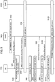
- FIG. 1 is an overall structural diagram of a radio communication system 10 according to the present embodiment.
- the radio communication system 10 is a radio communication system that uses the Long Term Evolution (LTE) and the 5G New Radio (NR), and includes a core network 20 and a user device (User Equipment) 200 (hereinafter, "UE 200").
- UE 200 User Equipment
- a radio base station 100A (hereinafter, "eNB 100A”) and a radio base station 100B (hereinafter, "gNB 100B”) are connected to the core network 20.
- the core network 20 can be a core network of the LTE system (EPC (Evolved Packet Core)) or can be a core network of the NR system (NextGen Core).
- EPC Evolved Packet Core
- NextGen Core NextGen Core
- the eNB 100A is a radio base station (eNB) of the LTE system and can constitute a master base station.
- the eNB 100A will be appropriately represented as LTE MeNB.
- the gNB 100B is a radio base station (gNB) of the NR system, and can constitute a secondary base station.
- the gNB 100B will be appropriately called as NR SgNB (or simply SgNB).
- the eNB 100A forms a cell C1.
- the gNB 100B forms a cell C2.
- the cell C1 is a macro cell and the cell C2 is a small cell.
- the cell C1 and the cell C2 can be formed in a plurality.
- a master cell group (MCG) is constituted by the cell C1 formed by the eNB 100A.
- a secondary cell group (SCG) is constituted by the cell C2 formed by the gNB 100B.
- FIG. 2 shows a protocol stack of the eNB 100A (LTE MeNB) and the gNB 100B (NR SgNB).
- the eNB 100A includes MAC (Medium Access Control) layer (MAC LTE ), RLC (Radio Link Control) layer (RLC LTE ), PDCP (Packet Data Convergence Protocol) layer (PDCP LTE ), and AS (Access Stratum) sublayer (New AS sublayer LTE ).
- MAC LTE Medium Access Control
- RLC LTE Radio Link Control
- PDCP Packet Data Convergence Protocol
- AS Access Stratum sublayer
- the gNB 100B includes MAC (Medium Access Control) layer (MAC NR ), RLC (Radio Link Control) layer (RLC NR ), PDCP (Packet Data Convergence Protocol) layer (PDCP NR ), and AS (Access Stratum) sublayer (New AS sublayer NR ).
- MAC NR Medium Access Control
- RLC NR Radio Link Control
- PDCP Packet Data Convergence Protocol
- AS Access Stratum sublayer
- the New AS sublayers is necessary when connecting to the NextGen Core.
- layers stipulated as per the conventional QoS mechanism are necessary.
- a control plane (C plane) and a user plane (U plane) are configured between the core network 20 (EPC) and the eNB 100A, but only the U plane is configured between the core network 20 (EPC) and the gNB 100B.
- Each of the eNB 100A and the gNB 100B includes a not-shown physical layer below the MAC layer.
- the AS sublayer (New AS sublayer LTE and New AS sublayer NR ) includes RRC (Radio Resource Control) such as RRC Connection Reconfiguration and the like explained later.
- RRC Radio Resource Control
- the eNB 100A and the gNB 100B are connected to the core network 20 (EPC) via S1-U interface. Moreover, the eNB 100A and the gNB 100B are connected to each other via X interface (Xx/Xn). As shown in FIG. 2 , the eNB 100A includes the RLC layer (RLC LTE ) for the X interface, and connects to the PDCP layer (PDCP NR ) of the gNB 100B via the X interface.
- RLC LTE the RLC layer
- PDCP NR PDCP layer
- a split bearer 0B SP (not shown in FIG. 2 , refer to FIG. 6 and the like) that goes from the core network 20 via the secondary cell group (SCG) and from the secondary cell group splits toward the radio base station (eNB 100A) included in the master cell group (MCG), specifically, Split bearer via SCG is configured.
- a functional block configuration of the radio communication system 10 is explained below. Specifically, functional block configurations of the eNB 100A and the UE 200 are explained below.
- FIG. 3 is a functional block diagram of the eNB 100A and the gNB 100B.
- the eNB 100A is cited as an example.
- the gNB 100B is different from the eNB 100A in that the gNB 100B is the radio base station of the NR system and constitutes the secondary base station in the present embodiment.
- the eNB 100A includes a radio communication unit 110, a connection controlling unit 120, a failure notification receiving unit 130, and a resource controlling unit 140.
- the eNB 100A provides functions of each layer in the protocol stack shown in FIG. 2 via the functional blocks shown in FIG. 3 . Furthermore, in FIG. 3 , only the functional blocks related to the present invention are shown.
- the radio communication unit 110 performs radio communication using the LTE system. Specifically, the radio communication unit 110 transmits to / receives from the UE 200 a radio signal using the LTE system. The user data or control data is multiplexed in the radio signal.
- the connection controlling unit 120 controls the connection between the eNB 100A and the UE 200, and the connection between the eNB 100A and the gNB 100B. Specifically, the connection controlling unit 120 controls the connections with the UE 200 in the RRC layer. Moreover, the connection controlling unit 120 controls the connections with the gNB 100B via the X interface (Xx/Xn).
- the connection controlling unit 120 transmits to the UE 200 a connection message (RRC message) to configure the split bearer B SP (refer to FIG. 6 and the like) .
- the connection controlling unit 120 is capable of transmitting to the UE 200 the RRC Connection Reconfiguration that includes an information element that allows the UE 200 to deactivate the secondary cell group (SCG) under a predetermined condition.
- to deactivate means to retain the resources used for configuring the split bearer B SP without releasing, and, as an operation of the UE 200, not to transmit any uplink signal of the cell, and not to monitor PDCCH, too.
- the UE 200 performs a downlink quality measurement by using downlink synchronization / reference signals and the like, but the measurement period is longer than that of in the RRC Connected state.
- the connection controlling unit 120 can transmit to the UE 200 the RRC Connection Reconfiguration that includes an information element that allows the UE 200 to remove an identifier of the cell quality measurement in the SCG.
- the RRC Connection Reconfiguration can include an information element that allows the UE 200 to remove MeasId that is used for identifying the quality measurement performed by the UE 200 of Primary SCell (PSCell) and Secondary Cell (SCell) included in the SCG.
- PSCell Primary SCell
- SCell Secondary Cell
- the MeasId is stipulated in Chapter 6.3.5 and the like of 3GPP TS36.331, and is used for identifying the configuration of the quality measurement of the cell (for example, the relationship between a measurement object (measObject) and a report configuration (reportConfig)).
- the UE 200 removes the MeasId in the SCG, the quality measurement in the SCG is stopped. In other words, when the UE 200 removes the MeasId, the quality measurement in the SCG is not performed.
- connection controlling unit 120 can transmit to the gNB 100B (another radio base station) a resource modification request (Secondary Node Modification Request) that instructs to release only the resources from a predetermined layer and below in the SCG of the split bearer B SP .
- a resource modification request (Secondary Node Modification Request) that instructs to release only the resources from a predetermined layer and below in the SCG of the split bearer B SP .
- the connection controlling unit 120 can transmit to the gNB 100B the Secondary Node Modification Request that instructs to release the resources from the RLC layer and below, in other words, the resources of the RLC NR and the MAC NR (including the physical layer) of the gNB 100B.
- S-RLF failure notification
- the connection controlling unit 120 can transmit to the gNB 100B the Secondary Node Modification Request that instructs to release the resources from the RLC layer and below, in other words, the resources of the RLC NR and the MAC NR (including the physical layer) of the gNB 100B.
- the connection controlling unit 120 can configure the split bearer B SP in which the released resources are reused.
- connection controlling unit 120 (corresponds to the gNB 100B in the present embodiment) can configure a new split bearer B SP .
- the failure notification receiving unit 130 receives from the UE 200 a notification of the radio link failure (RLF) in the master cell group (MCG) and the secondary cell group (SCG) .
- the failure notification receiving unit 130 receives from the UE 200 a failure notification (SCG Failure Information) that indicates that the RLF in the SCG (referred to as S-RLF) has occurred.
- SCG Failure Information failure notification
- the resource controlling unit 140 controls the resources in each layer of the protocol stack shown in FIG. 2 . Specifically, the resource controlling unit 140 controls the resources required in each layer according to the set state of the master cell group (MCG) and the secondary cell group (SCG) .
- the resource controlling unit 140 (corresponds to the gNB 100B in the present embodiment) releases, based on the resource modification request (Secondary Node Modification Request) received from the eNB 100A, the resources from the predetermined layer and below (specifically, from the RLC layer and below) in the SCG of the split bearer B SP .
- the resource modification request Secondary Node Modification Request
- the resource controlling unit 140 releases only the MAC NR and the RLC NR , among the MAC NR , the RLC NR , the PDCP NR , and the New AS sublayer NR (refer to FIG. 2 ) that constitute the split bearer B SP .
- FIG. 4 is a functional block diagram of the UE 200.
- the UE 200 includes a radio communication unit 210, a connection controlling unit 220, a failure detecting unit 230, a cell setting unit 240, and a quality measuring unit 250.
- the UE 200 provides functions of each layer in the protocol stack shown in FIG. 2 via the functional blocks shown in FIG. 4 . Furthermore, in FIG. 4 , only the functional blocks related to the present invention are shown.
- the radio communication unit 210 performs radio communication using the LTE system and the NR system. Specifically, the radio communication unit 210 transmits to / receives from the eNB 100A a radio signal using the LTE system. Moreover, the radio communication unit 210 transmits to / receives from the gNB 100B a radio signal using the NR system. The user data or the control data is multiplexed in the radio signal.
- the connection controlling unit 220 controls the connection between the UE 200 and the eNB 100A, and the connection between the UE 200 and the gNB 100B. Specifically, the connection controlling unit 220 controls the connections in the RRC layer, based on the connection message (RRC message) transmitted from the eNB 100A or the gNB 100B.
- RRC message connection message
- connection controlling unit 220 performs, based on the RRC Connection Reconfiguration received from the eNB 100A (or the gNB 100B), a connection reconfiguration process in the RRC layer.
- the connection controlling unit 220 transmits to the eNB 100A (or the gNB 100B) RRC Connection Reconfiguration Complete that indicates that the connection reconfiguration process is completed.
- the failure detecting unit 230 detects the radio link failure (RLF) in the master cell group (MCG) and the secondary cell group (SCG).
- RLF radio link failure
- MCG master cell group
- SCG secondary cell group
- the failure detecting unit 230 detects the RLF in the SCG.
- the cell setting unit 240 performs settings related to the cells of the master cell group (MCG) or the secondary cell group (SCG) to which the UE 200 is connectable. Specifically, the cell setting unit 240 deactivates the SCG under a predetermined condition.
- the cell setting unit 240 deactivates the setting of the cell (the cell C2 in the present embodiment) included in the SCG.
- the cell setting unit 240 deactivates the setting of the cell included in the SCG.
- the cell setting unit 240 stops the quality measurement of the cell (the cell C2 in the present embodiment) included in the SCG.
- the quality measuring unit 250 measures a reception quality of the cells included in the master cell group (MCG) and the secondary cell group (SCG) . Specifically, the quality measuring unit 250 measures Reference Signal Received Power (RSRP), Reference Signal Received Quality (RSRQ), and the like of each cell, and transmits a report of measurement (Measurement Report) if a predetermined condition (entering condition) is fulfilled.
- RSRP Reference Signal Received Power
- RSRQ Reference Signal Received Quality
- Measurement Report a report of measurement if a predetermined condition (entering condition) is fulfilled.
- the quality measuring unit 250 can measure the reception quality in the SCG for a longer period than that before the release of the resources.
- FIG. 5 shows a control sequence of the split bearer that includes a scenario in which the radio link failure in the secondary cell group has occurred (Operation Example 1).
- the eNB 100A determines to allow the UE 200 to autonomously deactivate the SCG (Step S10) .
- the UE 200 is usually not authorized to autonomously deactivate the SCG. More specifically, it is stipulated in the LTE that even when the RLF is detected, the UE 200 cannot deactivate or activate the SCG if there is no instruction from the eNB 100A and the like (for example, refer to 3GPP R2-144062 and 3GPP R2-144721).
- Step S10 the UE 200 cannot autonomously deactivate the SCG.
- the eNB 100A transmits to the UE 200 the RRC Connection Reconfiguration that includes the information element to allow the UE 200 to deactivate the SCG (Step S20) . Based on the information element, the UE 200 recognizes that it is allowed to autonomously deactivate the SCG (Step S30).
- the UE 200 Based on the RRC Connection Reconfiguration, the UE 200 performs a configuration modification process of the RRC layer associated with the configuration of the split bearer in the SCG, and transmits to the eNB 100A the RRC Connection Reconfiguration Complete that indicates that the configuration modification process is completed (Step S40). Accordingly, the split bearer B SP is configured (Step S50). As explained above, the split bearer B SP is referred to as the Split bearer via SCG, but in FIG. 5 , the split bearer B SP is appropriately called as "SCG split bearer" for convenience.
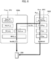
- FIG. 6 shows a configuration example of the split bearer B SP (Split bearer via SCG) (Operation Example 1).
- the split bearer B SP that is the Split bearer via SCG (shown with a thick line) splits at the PDCP NR of the gNB 100B toward the eNB 100A.
- a path of the configurable bearers (not limited to the split bearers) (refer to 3GPP TR38.804) is indicated by a thin line.
- the split bearer B SP that is split toward the eNB 100A provides a logical communication path to the UE 200 via the RLC LTE and the MAC LTE of the eNB 100A. Moreover, the split bearer B SP provides a logical communication path to the UE 200 via the RLC NR and the MAC NR of the gNB 100B. In the present operation example, the split bearer B SP is only deactivated and not released, and the configuration of the split bearer B SP is maintained in a state shown in FIG. 6 .
- the UE 200 detects the RLF in the SCG (S-RLF) (Step S60). Specifically, as explained above, the UE 200 detects the RLF in the SCG based on the detection condition of the RLF (for example, Chapter 10.1.6 of TS36.300).
- the UE 200 deactivates the cell included in the SCG (Step S70). Specifically, the UE 200 deactivates the Primary SCell (PSCell) and the Secondary Cell (SCell). Note that, as explained above, “deactivation” means to retain the resources used for configuring the split bearer B SP without releasing, and not to use those resources for data transmission / reception (equivalent to RRC Idle state).
- PSCell Primary SCell
- SCell Secondary Cell
- the UE 200 transmits to the eNB 100A the failure notification (SCG Failure Information) that indicates that the S-RLF has occurred (Step S80).
- SCG Failure Information SCG Failure Information
- the UE 200 transmits the SCG Failure Information that indicates that the S-RLF is recovered (Steps S90 and S100).
- the UE 200 activates the cells (PSCell and SCell) that were deactivated at Step S70 (Step S110).
- Step S120 the communication is resumed by using the reactivated split bearer B SP (SCG split bearer) (Step S120) .
- the UE 200 can autonomously deactivate the SCG when the S-RLF is detected, the UE 200 performs measurement reporting (transmitting Measurement Report) for a longer period than that when the SCG is in an active state. Accordingly, the power consumption of the UE 200 is reduced. Moreover, because the split bearer B SP itself retains the configuration, the signaling caused due to the repeated release and configuration of the split bearer, too, can be suppressed.
- FIG. 7 shows another control sequence of the split bearer that includes the scenario in which the radio link failure in the secondary cell group has occurred (Operation Example 1a). Operations that are different from that of Operation Example 1 explained above will be mainly explained below.
- the RRC Connection Reconfiguration that includes the information element that allows the UE 200 to remove the MeasId that is used for identifying the quality measurement performed by the UE 200 of the cells (PSCell and SCell) included in the SCG is transmitted to the UE 200 (Step S21).
- the UE 200 recognizes, based on the received information element, that the UE 200 is allowed to autonomously remove the MeasId that corresponds to the cell included in the SCG (Step S31).
- the processes performed at Steps S41 and S51 are the same as that performed at Steps S40 and S50 shown in FIG. 5 .
- the UE 200 detects the RLF in the SCG (S-RLF) (Step S61). Specifically, as explained above, the UE 200 detects the RLF in the SCG based on the detection condition of the RLF.
- the UE 200 removes the MeasId (Step S71). Specifically, the UE 200 removes the MeasIds that correspond to the PSCell and the SCell. As explained above, in the present embodiment, as the MeasId that corresponds to the cell included in the SCG, the MeasId that corresponds to the cell C2 is removed. Note that, the MeasId can be represented by using a predetermined number of integers, and a plurality of the MeasIds can be mapped to one cell.
- the UE 200 removes the Measld, the contents of the quality measurement and the reporting (measurement report) cannot be recognized, and, as a result, the quality measurement and the reporting (measurement report) are stopped.
- the UE 200 transmits to the eNB 100A the failure notification (SCG Failure Information) that indicates that the S-RLF has occurred (Step S81).
- SCG Failure Information SCG Failure Information
- the information element explained above can be an information element that indicates whether the UE 200 can autonomously remove the MeasId when the S-RLF occurs.
- the autonomous removal of the MeasId by the UE 200 is, for example, as stipulated in Chapter 5.5.2.2a of 3GPP TS36.331, primarily allowed when the serving cell is not configured, but, in the present embodiment, even when the radio link failure (RLF) in the SCG occurs, it is possible to instruct whether to allow the UE 200 to autonomously remove the MeasId.
- the UE 200 does not remove the MeasId, and performs operation according to the stipulations of the conventional dual connectivity.
- the UE 200 can autonomously remove the MeasId that corresponds to the cell included in the SCG when the S-RLF is detected, upon detecting the S-RLF, the UE 200 does not perform the measurement report related to the SCG. Accordingly, similar to Operation Example 1, the power consumption of the UE 200 is reduced. Moreover, because the split bearer B SP itself retains the configuration, the signaling caused due to the repeated release and configuration of the split bearer, too, can be suppressed.
- the UE 200 can set the MeasId to a disabled state. In other words, the MeasId itself is not removed, and can be set such that the MeasId cannot be used. Alternatively, the UE 200 can overwrite the existing MeasId with a dummy MeasId. By using such a configuration, the measurement report can be stopped.
- the UE 200 can deactivate the cell included in the SCG and remove the MeasId that corresponds to the cell included in the SCG. Moreover, in such a configuration, the UE 200 can perform only one of the processes that is executed first.
- FIG. 8 shows still another control sequence of the split bearer that includes the scenario in which the radio link failure in the secondary cell group has occurred (Operation Example 2).
- Operation Example 2 shows still another control sequence of the split bearer that includes the scenario in which the radio link failure in the secondary cell group has occurred (Operation Example 2).
- the eNB 100A transmits to the UE 200 the RRC Connection Reconfiguration that requests the configuration of the split bearer B SP (SCG split bearer) (Step S310).
- the UE 200 Based on the received RRC Connection Reconfiguration, the UE 200 configures the split bearer B SP and transmits to the eNB 100A the RRC Connection Reconfiguration Complete (Steps S320 and S330).
- the UE 200 transmits to the eNB 100A the failure notification (SCG Failure Information) that indicates that the S-RLF has occurred (Steps S340 and S350).
- SCG Failure Information SCG Failure Information
- the eNB 100A Based on the received SCG Failure Information, the eNB 100A transmits to the gNB 100B the Secondary Node Modification Request (resource modification request) (Step S360).
- the gNB 100B releases, based on the received Secondary Node Modification Request, RLC-Config, MACmain-Config, and individual radio resources (radio resources) from the SCG side. Specifically, the gNB 100B releases the resources of the RLC NR , the MAC NR , and the physical layer associated with the split bearer B SP (Step S370).
- the gNB 100B transmits to the eNB 100A Secondary Node Modification Request Acknowledgment that indicates that the resources are released (Step S380).
- the eNB 100A transmits to the UE 200, based on the received Secondary Node Modification Request Acknowledgment, the RRC Connection Reconfiguration that requests modification of the configuration of the split bearer B SP (Step S390).
- the UE 200 removes, based on the received RRC Connection Reconfiguration, SCG link (Leg) that constitutes the split bearer B SP (SCG split bearer) (Step S400) . Specifically, the UE 200 releases the RLC-Config, the MACmain-Config, and the individual radio resources (radio resources) that constitute the split bearer from the SCG side, that is, releases the resources of the RLC NR , the MAC NR , and the physical layer associated with the split bearer B SP .
- the UE 200 transmits to the eNB 100A the RRC Connection Reconfiguration Complete that indicates that the SCG link (Leg) is removed (Step S410).
- FIG. 9 shows a configuration example of the split bearer B SP (Split bearer via SCG) (Operation Example 2).
- the split bearer B SP (the resources that constitute the split bearer B SP ) within a section that directly moves toward the UE 200 from the gNB 100B (indicated by a dotted line in the figure) is released.
- the UE 200 can perform the measurement reporting (transmitting Measurement Report) for a longer period than that when the SCG is in the active state. Accordingly, similar to Operation Example 1, the power consumption of the UE 200 is reduced. Moreover, because the split bearer B SP at the MCG side itself retains the configuration, the signaling caused due to the repeated release and configuration of the split bearer can be suppressed.
- the resources of the SCG are released, wastage of the SCG resources that cannot actually be used can be eliminated.
- the RLC-Config, the MACmain-Config, and the individual radio resources (these resources can include common radio resources) from the SCG side are released, such configuration can contribute to efficient utilization of the resources.
- FIG. 10 shows still another control sequence of the split bearer that includes the scenario in which the radio link failure in the secondary cell group has occurred (Operation Example 3). Operations that are different from that of Operation Example 2 will be mainly explained below.
- the gNB 100B (NR SgNB) transmits the RRC message.
- Processes performed at Steps S310 to S360 shown in FIG. 10 are the same as the processes performed at Steps S310 to S360 shown in FIG. 8 .
- the gNB 100B transmits to the UE 200 the RRC Connection Reconfiguration (Step S370A) .
- the removal of the SCG link (Leg) that constitutes the split bearer B SP (SCG split bearer) and the release of the RLC-Config, the MACmain-Config, and the individual radio resources (radio resources) from the SCG side are instructed via that RRC Connection Reconfiguration.
- the gNB 100B and the UE 200 remove the SCG link (Leg) and release these resources (Step S380A).
- the UE 200 transmits to the gNB 100B the RRC Connection Reconfiguration Complete that indicates that the SCG link (Leg) is removed and the resources are released (Step S390A).
- the gNB 100B transmits to the eNB 100A, based on the received RRC Connection Reconfiguration Complete, the Secondary Node Modification Request Acknowledgment that indicates that the resources are released (Step S400A).
- FIG. 11 shows still another control sequence of the split bearer that includes the scenario in which the radio link failure in the secondary cell group has occurred (Operation Example 4). Operations that are different from that of Operation Example 2 will be mainly explained below.
- the SCG Failure Information is transmitted to the gNB 100B (NR SgNB) .
- Processes performed at Steps S310 to S340 shown in FIG. 11 are the same as the processes performed at Steps S310 to S340 shown in FIG. 8 .
- the UE 200 transmits to the gNB 100B the failure notification (SCG Failure Information) that indicates that the S-RLF has occurred (Step S350B).
- SCG Failure Information SCG Failure Information
- the gNB 100B releases, based on the received SCG Failure Information, the RLC-Config, the MACmain-Config, and the individual radio resources (radio resources) from the SCG side (Step S360B).
- the gNB 100B After releasing the resources, the gNB 100B transmits to the eNB 100A Secondary Node Modification Required that indicates that configuration modification on the SCG side is required (Step S370B).
- the eNB 100A transmits to the UE 200, based on the received Secondary Node Modification Required, the RRC Connection Reconfiguration that requests modification of the configuration of the split bearer B SP , (Step S380B).
- Step S380B Processes performed at Steps S390B and S400B shown in FIG. 11 are the same as the processes performed at Steps S400 and S410 shown in FIG. 8 .
- the eNB 100A transmits to the gNB 100B, based on the received RRC Connection Reconfiguration Complete, Secondary Node Modification Confirm that indicates that the configuration modification on the SCG side is completed (Step S410B).
- FIG. 12 shows still another control sequence of the split bearer that includes the scenario in which the radio link failure in the secondary cell group has occurred (Operation Example 5). Operations that are different from that of Operation Example 2 will be mainly explained below.
- the SCG Failure Information is transmitted to the gNB 100B (NR SgNB), and instead of the eNB 100A (LTE MeNB), the gNB 100B (NR SgNB) transmits the RRC message.
- Processes performed at Steps S310 to S340 shown in FIG. 12 are the same as the processes performed at Steps S310 to S340 shown in FIG. 8 .
- the UE 200 transmits to the gNB 100B the failure notification (SCG Failure Information) that indicates that the S-RLF has occurred (Step S350C).
- SCG Failure Information SCG Failure Information
- the gNB 100B transmits to the UE 200 the RRC Connection Reconfiguration based on the received SCG Failure Information (Step S360C).
- the removal of the SCG link (Leg) that constitutes the split bearer B SP (SCG split bearer) and the release of the RLC-Config, the MACmain-Config, and the individual radio resources (radio resources) from the SCG side are instructed via that RRC Connection Reconfiguration.
- the gNB 100B and the UE 200 remove the SCG link (Leg) and release these resources (Step S370C).
- the UE 200 transmits to the gNB 100B the RRC Connection Reconfiguration Complete that indicates that the SCG link (Leg) is removed and the resources are released (Step S380C).
- the gNB 100B transmits to the eNB 100A, based on the received RRC Connection Reconfiguration Complete, Secondary Node Reconfiguration Completed that indicates that the removal of the SCG link (Leg) that constitutes the split bearer B SP (SCG split bearer) and the release of the RLC-Config, the MACmain-Config, and the individual radio resources (radio resources) from the SCG side is completed (Step S390C).
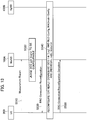
- FIG. 13 shows a configuration sequence of the split bearer B SP after a part of the resources from the SCG side (split bearer B SP ) is released (Operation Example 6).
- the eNB 100A LTE MeNB controls the configuration of the split bearer B SP .
- the UE 200 periodically transmits to the eNB 100A the report of measurement (Measurement Report) (Step S510).
- the eNB 100A judges, based on the received report of measurement, whether the split bearer in the SCG, specifically, the split bearer B SP (refer to FIG. 6 ) is configurable (Step S520).
- the split bearer B SP is configurable.
- the split bearer B SP may be judged as configurable in the same SCG (specifically, the NR SgNB) as that before a part of the resources from the SCG side is released, or may be judged as configurable in the different SCG than that before a part of the resources from the SCG side is released.
- the eNB 100A transmits to the UE 200 the RRC Connection Reconfiguration that requests to configure the split bearer B SP (S530).
- the UE 200 Based on the received RRC Connection Reconfiguration, the UE 200 either reconfigures the SCG link (Leg) that constitutes the split bearer B SP (SCG split bearer), and the RLC-Config, the MACmain-Config, and the individual radio resources (radio resource) from the SCG side, or configures a new split bearer B SP (Step S540).
- the split bearer B SP When configuring the split bearer B SP in the same SCG, the split bearer B SP is reconfigured. Specifically, only the SCG link (Leg) that is removed, and the RLC-Config, the MACmain-Config, and the individual radio resources (radio resource) from the SCG side that are released in the operation examples explained above are reconfigured. In other words, the other resources (PDCP NR , RLC LTE , and the like) that constitute the split bearer B SP are used in the retained state as is.
- split bearer B SP when the split bearer B SP is configured in a different SCG than that before a part of the resources from the SCG side is released, a new SCG split bearer is configured.
- a new SCG split bearer When a new SCG split bearer is configured, the retained resources of the split bearer B SP are released.
- the UE 200 transmits to the eNB 100A the RRC Connection Reconfiguration Complete that indicates that the SCG link (Leg) and the resources are reconfigured, or a new SCG split bearer is configured (Step S550).
- the split bearer B SP when the split bearer B SP is judged as configurable in the same SCG as that before a part of the resources from the SCG side is released, the split bearer B SP is reconfigured by utilizing the retained resources of the split bearer B SP , thereby making it possible to decrease the signaling amount while using the resources efficiently.
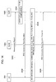
- FIG. 14 shows a configuration sequence of the split bearer B SP after a part of the resources from the SCG side (split bearer B SP ) is released (Operation Example 7).
- the gNB 100B controls the configuration of the split bearer B SP .
- Operation Example 7 differs from Operation Example 6 in that a controlling entity is the gNB 100B instead of the eNB 100A, but the processing content of each step is the same as that of Operation Example 6.
- processes performed at Steps S610 to S650 shown in FIG. 14 respectively correspond to the processes performed at Steps S510 to S550 shown in FIG. 13 .
- the UE 200 can autonomously deactivate the SCG when the S-RLF is detected, the UE 200 can perform the measurement reporting (transmitting Measurement Report) for a longer period than that when the SCG is in the active state.
- the UE 200 when the SCG is in the active state, the UE 200 performs Layer 3 measurement at the same frequency (200 milliseconds (ms)) as that when in the RRC Connected state, thereby making it difficult to reduce the power consumption.
- the measurement reporting can be performed for a longer period than that when in the RRC Connected state while maintaining the split bearer B SP , the power consumption of the UE 200 can be reduced.
- the split bearer B SP is judged as configurable in the same SCG as that before a part of the resources from the SCG side is released, the split bearer B SP is reconfigured by utilizing the retained resources of the split bearer B SP , the signaling amount can be decreased while utilizing the resources efficiently.
- the eNB 100A is a radio base station (eNB) of the LTE system and constitutes the master base station
- the gNB 100B is a radio base station (gNB) of the NR system and constitutes the secondary base station.
- the radio base station (gNB) of the NR system can constitute the master base station
- the radio base station (eNB) of the LTE system can constitute the secondary base station.
- each functional block may be realized by one device combined physically and / or logically.
- two or more devices separated physically and / or logically may be directly and / or indirectly connected (for example, wired and / or wireless) to each other, and each functional block may be realized by these plural devices.
- FIG. 15 is a diagram showing an example of a hardware configuration of the devices.
- each of the devices can be configured as a computer device including a processor 1001, a memory 1002, a storage 1003, a communication device 1004, an input device 1005, an output device 1006, and a bus 1007.
- the functional blocks of the devices can be realized by any of hardware elements of the computer device or a desired combination of the hardware elements.
- the processor 1001 for example, operates an operating system to control the entire computer.
- the processor 1001 can be configured with a central processing unit (CPU) including an interface with a peripheral device, a control device, a computing device, a register, and the like.
- CPU central processing unit
- the memory 1002 is a computer readable recording medium and is configured, for example, with at least one of ROM (Read Only Memory), EPROM (Erasable Programmable ROM), EEPROM (Electrically Erasable Programmable ROM), RAM (Random Access Memory), and the like.
- the memory 1002 can be called register, cache, main memory (main memory), and the like.
- the memory 1002 can store therein a computer program (computer program codes), software modules, and the like that can execute the method according to the above embodiments.
- the storage 1003 is a computer readable recording medium.
- Examples of the storage 1003 include an optical disk such as CD-ROM (Compact Disc ROM), a hard disk drive, a flexible disk, a magneto-optical disk (for example, a compact disk, a digital versatile disk, a Blu-ray (Registered Trademark) disk), a smart card, a flash memory (for example, a card, a stick, a key drive), a floppy (Registered Trademark) disk, a magnetic strip, and the like.
- the storage 1003 can be called an auxiliary storage device.
- the recording medium can be, for example, a database including the memory 1002 and / or the storage 1003, a server, or other appropriate medium.
- the communication device 1004 is hardware (transmission / reception device) capable of performing communication between computers via a wired and / or wireless network.
- the communication device 1004 is also called, for example, a network device, a network controller, a network card, a communication module, and the like.
- the input device 1005 is an input device (for example, a keyboard, a mouse, a microphone, a switch, a button, a sensor, and the like) that accepts input from the outside.
- the output device 1006 is an output device (for example, a display, a speaker, an LED lamp, and the like) that outputs data to the outside. Note that, the input device 1005 and the output device 1006 may be integrated (for example, a touch screen).
- the respective devices such as the processor 1001 and the memory 1002, are connected to each other with the bus 1007 for communicating information there among.
- the bus 1007 can be constituted by a single bus or can be constituted by separate buses between the devices.
- the manner of notification of information is not limited to the one explained in the embodiments, and the notification may be performed in other manner.
- the notification of information can be performed by physical layer signaling (for example, DCI (Downlink Control Information), UCI (Uplink Control Information)), upper layer signaling (for example, RRC signaling, MAC (Medium Access Control) signaling, notification information (MIB (Master Information Block), SIB (System Information Block)), other signals, or a combination thereof.
- the RRC signaling can be called an RRC message
- the RRC signaling can be, for example, an RRC Connection Setup message, an RRC Connection Reconfiguration message, and the like.
- the input / output information can be stored in a specific location (for example, a memory) or can be managed in a management table.
- the information to be input / output can be overwritten, updated, or added.
- the information can be deleted after outputting.
- the inputted information can be transmitted to another device.
- the specific operations performed by the eNB 100A can be performed by another network node (device) .
- functions of the eNB 100A can be provided by combining a plurality of other network nodes.
- the used parameter and the like can be represented by an absolute value, can be expressed as a relative value from a predetermined value, or can be represented by corresponding other information.
- the radio resource can be indicated by an index.
- the eNB 100A can accommodate one or more (for example, three) cells (also called sectors).
- the entire coverage area of the base station can be divided into a plurality of smaller areas.
- communication service can be provided by a base station subsystem (for example, a small base station for indoor use RRH: Remote Radio Head).
- the term “cell” or “sector” refers to a part or all of the coverage area of a base station and / or a base station subsystem that performs communication service in this coverage.
- base station eNB
- cell refers to a part or all of the coverage area of a base station and / or a base station subsystem that performs communication service in this coverage.
- base station eNode B
- gNB gNode B
- the base station can also be referred to as a fixed station, Node B, eNode B (eNB), gNode B (gNB), an access point, a femtocell, a small cell, and the like.
- the UE 200 is called by the persons skilled in the art as a subscriber station, a mobile unit, a subscriber unit, a radio unit, a remote unit, a mobile device, a radio device, a radio communication device, a remote device, a mobile subscriber station, an access terminal, a mobile terminal, a radio terminal, a remote terminal, a handset, a user agent, a mobile client, a client, or with some other suitable term.
- the phrase “based on” does not mean “based only on” unless explicitly stated otherwise. In other words, the phrase “based on” means both “based only on” and “based at least on”.
- any reference to an element using a designation such as “first”, “second”, and the like used in the present specification generally does not limit the amount or order of those elements. Such designations can be used in the present specification as a convenient way to distinguish between two or more elements. Thus, the reference to the first and second elements does not imply that only two elements can be adopted, or that the first element must precede the second element in some or the other manner.
- radio communication system and the radio base station explained above are useful in that, even when a split bearer via a secondary cell group (SCG) is configured, it is possible to reduce the power consumption of a user device and suppress an increase in a signaling amount due to repeated release and configuration of the split bearer.
- SCG secondary cell group
Landscapes
- Engineering & Computer Science (AREA)
- Computer Networks & Wireless Communication (AREA)
- Signal Processing (AREA)
- Mobile Radio Communication Systems (AREA)
Abstract
Description
- The present invention relates to a radio communication system and a radio base station that are capable of configuring a split bearer.
- 3rd Generation Partnership Project (3GPP) specifies Long Term Evolution (LTE), and with an aim of further speeding, specifies LTE-Advanced (hereinafter, it is assumed that the LTE includes the LTE-Advanced). Moreover, in the 3GPP, specifications of a successor system of the LTE called 5G New Radio (NR) and the like are being studied.
- Specifically, as a type of a bearer in dual connectivity (DC) using a radio base station of an LTE system and a radio base station of an NR system, a split bearer via a secondary cell group (SCG) (Split bearer via SCG) is stipulated in Non-Patent Document 1.
- In the Split bearer via SCG, when a master base station is the radio base station of the LTE system (hereinafter, "LTE MeNB") and a secondary base station is the radio base station of the NR system (hereinafter, "NR SgNB" or simply "SgNB"), the bearer for a user plane (S1-U) between a core network and the radio base station is configured only between the core network (EPC (Evolved Packet Core)) and the NR SgNB. The bearer splits toward the LTE MeNB at the PDCP layer of the NR SgNB and constitutes a split bearer.
- User data (for example, downlink data) is transmitted to a user device (UE) from the LTE MeNB and the NR SgNB via the split bearer. Accordingly, the dual connectivity using the LTE MeNB and the NR SgNB is realized.
- Non-Patent Document 1: 3GPP TR 38.804 V14.0.0 Section 5.2.1.2 Bearer types for DualConnectivity between LTE and NR, 3rd Generation Partnership Project; Technical Specification Group Radio Access Network; Study on New Radio Access Technology; Radio Interface Protocol Aspects Release 14), 3GPP, March 2017
- As explained above, a configuration in which, when a secondary base station is a radio base station of the NR system (NR SgNB), LTE MeNB forms a macro cell and the NR SgNB forms a small cell is stipulated in Non-Patent Document 1.
- In such a configuration, when UE moves, it is assumed that the UE frequently goes out of the coverage area of the small cell. Therefore, if a split bearer via the SCG is configured, it becomes necessary to release that split bearer and reconfigure a new bearer via only a master cell group (MCG) .
- Furthermore, it is assumed that when the UE moves into the coverage area of the small cell after the split bearer is released, a new split bearer is configured and the dual connectivity is resumed. In other words, increase in the signaling amount due to such release and configuration of the split bearer becomes a concern.
- As a solution to such a problem, one approach is to use a mechanism stipulated in LTE Release-12. Specifically, in the LTE Release-12, it is stipulated that, upon detecting a radio link failure (RLF), a certain radio base station (SeNB) that forms Primary SCell (PSCell) reports to the master base station (MeNB) the RLF, and the MeNB that receives the report performs operation to remove the SCG. In such a configuration, to suppress the increase in the signaling amount due to the release and configuration of the split bearer explained above, a solution in which the MeNB that receives the report can retain the SCG without removing the same can be thought.
- However, if the SCG is retained regardless of the occurrence of the RLF, the PSCell and SCell remain active, that is, a connected state (RRC Connected state) in the radio resource control layer (RRC layer) of these cells is maintained. Consequently, the UE periodically repeats the quality measurement of the cells and reporting (measurement report), and higher power consumption becomes a problem.
- The present invention has been made in view of the above circumstances. It is an object of the present invention to provide a radio communication system and a radio base station capable of reducing power consumption of a user device and suppressing the increase in the signaling amount due to repeated release and configuration of a split bearer, even when a split bearer via a secondary cell group (SCG) is configured.
- According to one aspect of the present invention, a radio communication system is capable of configuring a split bearer that goes from a core network via a secondary cell group and from the secondary cell group splits toward a radio base station included in a master cell group, and data is transmitted to a user device via the split bearer. The radio base station includes a connection controlling unit that transmits to the user device a connection message to configure the split bearer. The connection message includes an information element that allows deactivation of the secondary cell group under a predetermined condition. The user device includes a cell setting unit that deactivates setting of a cell included in the secondary cell group when the received connection message includes the information element and a radio link failure in the secondary cell group is detected.
- According to another aspect of the present invention, a radio base station included in a radio communication system that is capable of configuring a split bearer that goes from a core network via a secondary cell group and from the secondary cell group splits toward a radio base station included in a master cell group, and in which data is transmitted to a user device via the split bearer, includes a connection controlling unit that transmits to the user device a connection message to configure the split bearer. The connection message includes an information element that allows deactivation of the secondary cell group under a predetermined condition.
- According to still another aspect of the present invention, a radio communication system is capable of configuring a split bearer that goes from a core network via a secondary cell group and from an another radio base station included in the secondary cell group splits toward a radio base station included in a master cell group, and data is transmitted to a user device via the split bearer. The radio base station includes a failure notification receiving unit that receives from the user device a failure notification that indicates that a radio link failure in the secondary cell group has occurred; and a connection controlling unit that transmits to the another radio base station, when the failure notification receiving unit receives the failure notification, a resource modification request that instructs to release only resources from a predetermined layer and below in the secondary cell group of the split bearer. The another radio base station includes a resource controlling unit that releases, based on the received resource modification request, the resources from the predetermined layer and below in the secondary cell group of the split bearer.
- According to still another aspect of the present invention, a radio base station included in a radio communication system that is capable of configuring a split bearer that goes from a core network via a secondary cell group and from a radio base station included in the secondary cell group splits toward a master cell group, and in which data is transmitted to a user device via the split bearer, includes a failure notification receiving unit that receives from the user device a failure notification that indicates that a radio link failure in the secondary cell group has occurred; and a resource controlling unit that releases, when the failure notification receiving unit receives the failure notification, only resources from a predetermined layer and below in the secondary cell group of the split bearer.
- According to still another aspect of the present invention, a radio communication system is capable of configuring a split bearer that goes from a core network via a secondary cell group and from the secondary cell group splits toward a radio base station included in a master cell group, and data is transmitted to a user device via the split bearer. The radio base station includes a connection controlling unit that transmits to the user device a connection message to configure the split bearer. The connection message includes an information element that allows removal of an identifier of a cell quality measurement in the secondary cell group. The user device includes a cell setting unit that stops quality measurement of cells included in the secondary cell group when the received connection message includes the information element and a radio link failure in the secondary cell group is detected.
-
-
FIG. 1 is an overall structural diagram of aradio communication system 10. -
FIG. 2 is a diagram showing a protocol stack of eNB 100A (LTE MeNB) and gNB 100B (NR SgNB). -
FIG. 3 is a functional block diagram of the eNB 100A and the gNB 100B. -
FIG. 4 is a functional block diagram of UE 200. -
FIG. 5 is a diagram showing a control sequence of a split bearer that includes a scenario in which a radio link failure in a secondary cell group has occurred (Operation Example 1). -
FIG. 6 is a diagram showing a configuration example of a split bearer BSP (Split bearer via SCG) (Operation Example 1) . -
FIG. 7 is a diagram showing another control sequence of the split bearer that includes the scenario in which the radio link failure in the secondary cell group has occurred (Operation Example la). -
FIG. 8 is a diagram showing still another control sequence of the split bearer that includes the scenario in which the radio link failure in the secondary cell group has occurred (Operation Example 2). -
FIG. 9 is a diagram showing a configuration example of the split bearer BSP (Split bearer via SCG) (Operation Example 2) . -
FIG. 10 is a diagram showing still another control sequence of the split bearer that includes the scenario in which the radio link failure in the secondary cell group has occurred (Operation Example 3). -
FIG. 11 is a diagram showing still another control sequence of the split bearer that includes the scenario in which the radio link failure in the secondary cell group has occurred (Operation Example 4). -
FIG. 12 is a diagram showing still another control sequence of the split bearer that includes the scenario in which the radio link failure in the secondary cell group has occurred (Operation Example 5). -
FIG. 13 is a diagram showing a configuration sequence of the split bearer BSP after a part of resources from SCG side (split bearer BSP) is released (Operation Example 6). -
FIG. 14 is a diagram showing a configuration sequence of the split bearer BSP after a part of the resources from the SCG side (split bearer BSP) is released (Operation Example 7) . -
FIG. 15 is a diagram showing an example of a hardware configuration of the eNB 100A, 100B and the UE 200. - Exemplary embodiments of the present invention are explained below with reference to the accompanying drawings. In the drawings, structural elements having the same function or configuration are indicated by the same or similar reference numerals and the explanation thereof is appropriately omitted.
-
FIG. 1 is an overall structural diagram of aradio communication system 10 according to the present embodiment. Theradio communication system 10 is a radio communication system that uses the Long Term Evolution (LTE) and the 5G New Radio (NR), and includes acore network 20 and a user device (User Equipment) 200 (hereinafter, "UE 200"). Aradio base station 100A (hereinafter, "eNB 100A") and aradio base station 100B (hereinafter, "gNB 100B") are connected to thecore network 20. - The
core network 20 can be a core network of the LTE system (EPC (Evolved Packet Core)) or can be a core network of the NR system (NextGen Core). - In the present embodiment, the eNB 100A is a radio base station (eNB) of the LTE system and can constitute a master base station. Hereinafter, the eNB 100A will be appropriately represented as LTE MeNB. The
gNB 100B is a radio base station (gNB) of the NR system, and can constitute a secondary base station. Hereinafter, thegNB 100B will be appropriately called as NR SgNB (or simply SgNB). - The
eNB 100A forms a cell C1. ThegNB 100B forms a cell C2. In the present embodiment, the cell C1 is a macro cell and the cell C2 is a small cell. Alternatively, the cell C1 and the cell C2 can be formed in a plurality. - A master cell group (MCG) is constituted by the cell C1 formed by the
eNB 100A. A secondary cell group (SCG) is constituted by the cell C2 formed by thegNB 100B. -
FIG. 2 shows a protocol stack of theeNB 100A (LTE MeNB) and thegNB 100B (NR SgNB). As shown inFIG. 2 , theeNB 100A includes MAC (Medium Access Control) layer (MACLTE), RLC (Radio Link Control) layer (RLCLTE), PDCP (Packet Data Convergence Protocol) layer (PDCPLTE), and AS (Access Stratum) sublayer (New AS sublayerLTE). - Similarly, the
gNB 100B includes MAC (Medium Access Control) layer (MACNR), RLC (Radio Link Control) layer (RLCNR), PDCP (Packet Data Convergence Protocol) layer (PDCPNR), and AS (Access Stratum) sublayer (New AS sublayerNR). The New AS sublayers is necessary when connecting to the NextGen Core. When connecting to the EPC, layers stipulated as per the conventional QoS mechanism are necessary. - A control plane (C plane) and a user plane (U plane) are configured between the core network 20 (EPC) and the
eNB 100A, but only the U plane is configured between the core network 20 (EPC) and thegNB 100B. - Each of the
eNB 100A and thegNB 100B includes a not-shown physical layer below the MAC layer. Moreover, the AS sublayer (New AS sublayerLTE and New AS sublayerNR) includes RRC (Radio Resource Control) such as RRC Connection Reconfiguration and the like explained later. - The
eNB 100A and thegNB 100B are connected to the core network 20 (EPC) via S1-U interface. Moreover, theeNB 100A and thegNB 100B are connected to each other via X interface (Xx/Xn). As shown inFIG. 2 , theeNB 100A includes the RLC layer (RLCLTE) for the X interface, and connects to the PDCP layer (PDCPNR) of thegNB 100B via the X interface. - Moreover, in the present embodiment, a split bearer 0BSP (not shown in
FIG. 2 , refer toFIG. 6 and the like) that goes from thecore network 20 via the secondary cell group (SCG) and from the secondary cell group splits toward the radio base station (eNB 100A) included in the master cell group (MCG), specifically, Split bearer via SCG is configured. - Data transmitted to the
UE 200 from thecore network 20, specifically, downlink user data is transmitted to theUE 200 via the split bearer BSP. - A functional block configuration of the
radio communication system 10 is explained below. Specifically, functional block configurations of theeNB 100A and theUE 200 are explained below. -
FIG. 3 is a functional block diagram of theeNB 100A and thegNB 100B. Hereinafter, unless particularly stated, theeNB 100A is cited as an example. As explained above, thegNB 100B is different from theeNB 100A in that thegNB 100B is the radio base station of the NR system and constitutes the secondary base station in the present embodiment. - As shown in
FIG. 3 , theeNB 100A includes aradio communication unit 110, aconnection controlling unit 120, a failurenotification receiving unit 130, and aresource controlling unit 140. - The
eNB 100A provides functions of each layer in the protocol stack shown inFIG. 2 via the functional blocks shown inFIG. 3 . Furthermore, inFIG. 3 , only the functional blocks related to the present invention are shown. - The
radio communication unit 110 performs radio communication using the LTE system. Specifically, theradio communication unit 110 transmits to / receives from the UE 200 a radio signal using the LTE system. The user data or control data is multiplexed in the radio signal. - The
connection controlling unit 120 controls the connection between theeNB 100A and theUE 200, and the connection between theeNB 100A and thegNB 100B. Specifically, theconnection controlling unit 120 controls the connections with theUE 200 in the RRC layer. Moreover, theconnection controlling unit 120 controls the connections with thegNB 100B via the X interface (Xx/Xn). - In particular, in the present embodiment, the
connection controlling unit 120 transmits to the UE 200 a connection message (RRC message) to configure the split bearer BSP (refer toFIG. 6 and the like) . Specifically, theconnection controlling unit 120 is capable of transmitting to theUE 200 the RRC Connection Reconfiguration that includes an information element that allows theUE 200 to deactivate the secondary cell group (SCG) under a predetermined condition. - In the present embodiment, "to deactivate" means to retain the resources used for configuring the split bearer BSP without releasing, and, as an operation of the
UE 200, not to transmit any uplink signal of the cell, and not to monitor PDCCH, too. TheUE 200 performs a downlink quality measurement by using downlink synchronization / reference signals and the like, but the measurement period is longer than that of in the RRC Connected state. - Moreover, the
connection controlling unit 120 can transmit to theUE 200 the RRC Connection Reconfiguration that includes an information element that allows theUE 200 to remove an identifier of the cell quality measurement in the SCG. Specifically, the RRC Connection Reconfiguration can include an information element that allows theUE 200 to remove MeasId that is used for identifying the quality measurement performed by theUE 200 of Primary SCell (PSCell) and Secondary Cell (SCell) included in the SCG. - Specifically, the MeasId is stipulated in Chapter 6.3.5 and the like of 3GPP TS36.331, and is used for identifying the configuration of the quality measurement of the cell (for example, the relationship between a measurement object (measObject) and a report configuration (reportConfig)). When the
UE 200 removes the MeasId in the SCG, the quality measurement in the SCG is stopped. In other words, when theUE 200 removes the MeasId, the quality measurement in the SCG is not performed. - Moreover, the
connection controlling unit 120 can transmit to thegNB 100B (another radio base station) a resource modification request (Secondary Node Modification Request) that instructs to release only the resources from a predetermined layer and below in the SCG of the split bearer BSP. - Specifically, when the failure
notification receiving unit 130 receives a failure notification (S-RLF), theconnection controlling unit 120 can transmit to thegNB 100B the Secondary Node Modification Request that instructs to release the resources from the RLC layer and below, in other words, the resources of the RLCNR and the MACNR (including the physical layer) of thegNB 100B. - When a part of the resources that constitute the split bearer BSP is released in such a manner, when reconnecting the
UE 200 to the same SCG (that is, thegNB 100B) as that before the release of the resources, the connection controlling unit 120 (corresponds to thegNB 100B in the present embodiment) can configure the split bearer BSP in which the released resources are reused. - On the other hand, when a part of the resources that constitute the split bearer BSP is released in the manner explained above, when connecting the
UE 200 to a different SCG than that before the release of the resources, the connection controlling unit 120 (corresponds to thegNB 100B in the present embodiment) can configure a new split bearer BSP. - The failure
notification receiving unit 130 receives from the UE 200 a notification of the radio link failure (RLF) in the master cell group (MCG) and the secondary cell group (SCG) . In particular, in the present embodiment, the failurenotification receiving unit 130 receives from the UE 200 a failure notification (SCG Failure Information) that indicates that the RLF in the SCG (referred to as S-RLF) has occurred. - The
resource controlling unit 140 controls the resources in each layer of the protocol stack shown inFIG. 2 . Specifically, theresource controlling unit 140 controls the resources required in each layer according to the set state of the master cell group (MCG) and the secondary cell group (SCG) . - In particular, in the present embodiment, the resource controlling unit 140 (corresponds to the
gNB 100B in the present embodiment) releases, based on the resource modification request (Secondary Node Modification Request) received from theeNB 100A, the resources from the predetermined layer and below (specifically, from the RLC layer and below) in the SCG of the split bearer BSP. - In other words, the
resource controlling unit 140 releases only the MACNR and the RLCNR, among the MACNR, the RLCNR, the PDCPNR, and the New AS sublayerNR (refer toFIG. 2 ) that constitute the split bearer BSP. -
FIG. 4 is a functional block diagram of theUE 200. As shown inFIG. 4 , theUE 200 includes aradio communication unit 210, aconnection controlling unit 220, afailure detecting unit 230, acell setting unit 240, and aquality measuring unit 250. TheUE 200 provides functions of each layer in the protocol stack shown inFIG. 2 via the functional blocks shown inFIG. 4 . Furthermore, inFIG. 4 , only the functional blocks related to the present invention are shown. - The
radio communication unit 210 performs radio communication using the LTE system and the NR system. Specifically, theradio communication unit 210 transmits to / receives from theeNB 100A a radio signal using the LTE system. Moreover, theradio communication unit 210 transmits to / receives from thegNB 100B a radio signal using the NR system. The user data or the control data is multiplexed in the radio signal. - The
connection controlling unit 220 controls the connection between theUE 200 and theeNB 100A, and the connection between theUE 200 and thegNB 100B. Specifically, theconnection controlling unit 220 controls the connections in the RRC layer, based on the connection message (RRC message) transmitted from theeNB 100A or thegNB 100B. - More specifically, the
connection controlling unit 220 performs, based on the RRC Connection Reconfiguration received from theeNB 100A (or thegNB 100B), a connection reconfiguration process in the RRC layer. Theconnection controlling unit 220 transmits to theeNB 100A (or thegNB 100B) RRC Connection Reconfiguration Complete that indicates that the connection reconfiguration process is completed. - The
failure detecting unit 230 detects the radio link failure (RLF) in the master cell group (MCG) and the secondary cell group (SCG). In particular, in the present embodiment, based on the detection condition of the RLF stipulated in the 3GPP Technical Standard (TS) (for example, Chapter 10.1.6 of TS36.300), thefailure detecting unit 230 detects the RLF in the SCG. - The
cell setting unit 240 performs settings related to the cells of the master cell group (MCG) or the secondary cell group (SCG) to which theUE 200 is connectable. Specifically, thecell setting unit 240 deactivates the SCG under a predetermined condition. - More specifically, when the RRC message (RRC Connection Reconfiguration) received by the
connection controlling unit 220 includes the information element that allows deactivation, and when the radio link failure (RLF) in the SCG is detected, thecell setting unit 240 deactivates the setting of the cell (the cell C2 in the present embodiment) included in the SCG. - Particularly, in the present embodiment, even when the
UE 200 is not allowed to autonomously deactivate the setting of the cell included in the SCG, if the received RRC Connection Reconfiguration includes such an information element and the RLF in the SCG is detected, thecell setting unit 240 deactivates the setting of the cell included in the SCG. - Moreover, when the RRC message (RRC Connection Reconfiguration) received by the connection controlling unit 22C includes the information element that allows to remove the identifier of the cell quality measurement in the SCG, and when the radio link failure (RLF) in the SCG is detected, the
cell setting unit 240 stops the quality measurement of the cell (the cell C2 in the present embodiment) included in the SCG. - The
quality measuring unit 250 measures a reception quality of the cells included in the master cell group (MCG) and the secondary cell group (SCG) . Specifically, thequality measuring unit 250 measures Reference Signal Received Power (RSRP), Reference Signal Received Quality (RSRQ), and the like of each cell, and transmits a report of measurement (Measurement Report) if a predetermined condition (entering condition) is fulfilled. - In particular, in the present embodiment, after a part of the resources (from the RLC layer and below) of the split bearer BSP in the
gNB 100B (NR SgNB) is released, thequality measuring unit 250 can measure the reception quality in the SCG for a longer period than that before the release of the resources. - Operation of the
radio communication system 10 is explained below. Specifically, operations related to the configuration and the release of the split bearer (Split bearer via SCG) performed by theeNB 100A (LTE MeNB), thegNB 100B (NR SgNB), and theUE 200 will be explained. - First, operation performed at the time of the radio link failure (RLF) in the secondary cell group (SCG) will be explained with reference to
FIGS. 5 to 12 . -
FIG. 5 shows a control sequence of the split bearer that includes a scenario in which the radio link failure in the secondary cell group has occurred (Operation Example 1). - As shown in
FIG. 5 , theeNB 100A determines to allow theUE 200 to autonomously deactivate the SCG (Step S10) . Specifically, in the dual connectivity (DC) of the LTE (for example, Release-12), theUE 200 is usually not authorized to autonomously deactivate the SCG. More specifically, it is stipulated in the LTE that even when the RLF is detected, theUE 200 cannot deactivate or activate the SCG if there is no instruction from theeNB 100A and the like (for example, refer to 3GPP R2-144062 and 3GPP R2-144721). - Furthermore, if not determined so at Step S10, the
UE 200 cannot autonomously deactivate the SCG. - The
eNB 100A transmits to theUE 200 the RRC Connection Reconfiguration that includes the information element to allow theUE 200 to deactivate the SCG (Step S20) . Based on the information element, theUE 200 recognizes that it is allowed to autonomously deactivate the SCG (Step S30). - Based on the RRC Connection Reconfiguration, the
UE 200 performs a configuration modification process of the RRC layer associated with the configuration of the split bearer in the SCG, and transmits to theeNB 100A the RRC Connection Reconfiguration Complete that indicates that the configuration modification process is completed (Step S40). Accordingly, the split bearer BSP is configured (Step S50). As explained above, the split bearer BSP is referred to as the Split bearer via SCG, but inFIG. 5 , the split bearer BSP is appropriately called as "SCG split bearer" for convenience. -
FIG. 6 shows a configuration example of the split bearer BSP (Split bearer via SCG) (Operation Example 1). As shown inFIG. 6 , the split bearer BSP that is the Split bearer via SCG (shown with a thick line) splits at the PDCPNR of thegNB 100B toward theeNB 100A. Furthermore, a path of the configurable bearers (not limited to the split bearers) (refer to 3GPP TR38.804) is indicated by a thin line. - The split bearer BSP that is split toward the
eNB 100A provides a logical communication path to theUE 200 via the RLCLTE and the MACLTE of theeNB 100A. Moreover, the split bearer BSP provides a logical communication path to theUE 200 via the RLCNR and the MACNR of thegNB 100B. In the present operation example, the split bearer BSP is only deactivated and not released, and the configuration of the split bearer BSP is maintained in a state shown inFIG. 6 . - Next, the
UE 200 detects the RLF in the SCG (S-RLF) (Step S60). Specifically, as explained above, theUE 200 detects the RLF in the SCG based on the detection condition of the RLF (for example, Chapter 10.1.6 of TS36.300). - Because the autonomous deactivation of the SCG is allowed, the
UE 200 deactivates the cell included in the SCG (Step S70). Specifically, theUE 200 deactivates the Primary SCell (PSCell) and the Secondary Cell (SCell). Note that, as explained above, "deactivation" means to retain the resources used for configuring the split bearer BSP without releasing, and not to use those resources for data transmission / reception (equivalent to RRC Idle state). - Moreover, the
UE 200 transmits to theeNB 100A the failure notification (SCG Failure Information) that indicates that the S-RLF has occurred (Step S80). - Subsequently, upon detecting recovery of the S-RLF, the
UE 200 transmits the SCG Failure Information that indicates that the S-RLF is recovered (Steps S90 and S100). - The
UE 200 activates the cells (PSCell and SCell) that were deactivated at Step S70 (Step S110). - As a result, the communication is resumed by using the reactivated split bearer BSP (SCG split bearer) (Step S120) .
- In this way, because the
UE 200 can autonomously deactivate the SCG when the S-RLF is detected, theUE 200 performs measurement reporting (transmitting Measurement Report) for a longer period than that when the SCG is in an active state. Accordingly, the power consumption of theUE 200 is reduced. Moreover, because the split bearer BSP itself retains the configuration, the signaling caused due to the repeated release and configuration of the split bearer, too, can be suppressed. -
FIG. 7 shows another control sequence of the split bearer that includes the scenario in which the radio link failure in the secondary cell group has occurred (Operation Example 1a). Operations that are different from that of Operation Example 1 explained above will be mainly explained below. - In Operation Example 1a, compared to Operation Example 1, the RRC message that includes the information element that allows the
UE 200 to remove the MeasId that is used for identifying the quality measurement performed by theUE 200 is used. - Specifically, as shown in
FIG. 7 , the RRC Connection Reconfiguration that includes the information element that allows theUE 200 to remove the MeasId that is used for identifying the quality measurement performed by theUE 200 of the cells (PSCell and SCell) included in the SCG is transmitted to the UE 200 (Step S21). - The
UE 200 recognizes, based on the received information element, that theUE 200 is allowed to autonomously remove the MeasId that corresponds to the cell included in the SCG (Step S31). The processes performed at Steps S41 and S51 are the same as that performed at Steps S40 and S50 shown inFIG. 5 . - Next, the
UE 200 detects the RLF in the SCG (S-RLF) (Step S61). Specifically, as explained above, theUE 200 detects the RLF in the SCG based on the detection condition of the RLF. - Because the
UE 200 is allowed to autonomously remove the MeasId that corresponds to the cell included in the SCG, theUE 200 removes the MeasId (Step S71). Specifically, theUE 200 removes the MeasIds that correspond to the PSCell and the SCell. As explained above, in the present embodiment, as the MeasId that corresponds to the cell included in the SCG, the MeasId that corresponds to the cell C2 is removed. Note that, the MeasId can be represented by using a predetermined number of integers, and a plurality of the MeasIds can be mapped to one cell. - Once the
UE 200 removes the Measld, the contents of the quality measurement and the reporting (measurement report) cannot be recognized, and, as a result, the quality measurement and the reporting (measurement report) are stopped. - Moreover, the
UE 200 transmits to theeNB 100A the failure notification (SCG Failure Information) that indicates that the S-RLF has occurred (Step S81). - Furthermore, the information element explained above can be an information element that indicates whether the
UE 200 can autonomously remove the MeasId when the S-RLF occurs. The autonomous removal of the MeasId by theUE 200 is, for example, as stipulated in Chapter 5.5.2.2a of 3GPP TS36.331, primarily allowed when the serving cell is not configured, but, in the present embodiment, even when the radio link failure (RLF) in the SCG occurs, it is possible to instruct whether to allow theUE 200 to autonomously remove the MeasId. - On the other hand, if the information element is not included, the
UE 200 does not remove the MeasId, and performs operation according to the stipulations of the conventional dual connectivity. - In this manner, because the
UE 200 can autonomously remove the MeasId that corresponds to the cell included in the SCG when the S-RLF is detected, upon detecting the S-RLF, theUE 200 does not perform the measurement report related to the SCG. Accordingly, similar to Operation Example 1, the power consumption of theUE 200 is reduced. Moreover, because the split bearer BSP itself retains the configuration, the signaling caused due to the repeated release and configuration of the split bearer, too, can be suppressed. - Alternatively, instead of autonomously removing the MeasId, the
UE 200 can set the MeasId to a disabled state. In other words, the MeasId itself is not removed, and can be set such that the MeasId cannot be used. Alternatively, theUE 200 can overwrite the existing MeasId with a dummy MeasId. By using such a configuration, the measurement report can be stopped. - Furthermore, configurations of Operation Example 1 and Operation Example 1a explained above can be used together. In other words, the
UE 200 can deactivate the cell included in the SCG and remove the MeasId that corresponds to the cell included in the SCG. Moreover, in such a configuration, theUE 200 can perform only one of the processes that is executed first. -
FIG. 8 shows still another control sequence of the split bearer that includes the scenario in which the radio link failure in the secondary cell group has occurred (Operation Example 2). In the following explanation, explanation of the operations that are similar to that of Operation Example 1 is appropriately omitted. - Furthermore, the combination of a transmission destination (LTE MeNB or NR SgNB) of the SCG Failure Information and a transmitting entity of the RRC message (LTE MeNB or NR SgNB) is different in Operation Examples 2 to 5.
- As shown in
FIG. 8 , theeNB 100A transmits to theUE 200 the RRC Connection Reconfiguration that requests the configuration of the split bearer BSP (SCG split bearer) (Step S310). - Based on the received RRC Connection Reconfiguration, the
UE 200 configures the split bearer BSP and transmits to theeNB 100A the RRC Connection Reconfiguration Complete (Steps S320 and S330). - Next, upon detecting the RLF in the SCG (S-RLF), the
UE 200 transmits to theeNB 100A the failure notification (SCG Failure Information) that indicates that the S-RLF has occurred (Steps S340 and S350). - Based on the received SCG Failure Information, the
eNB 100A transmits to thegNB 100B the Secondary Node Modification Request (resource modification request) (Step S360). - The
gNB 100B releases, based on the received Secondary Node Modification Request, RLC-Config, MACmain-Config, and individual radio resources (radio resources) from the SCG side. Specifically, thegNB 100B releases the resources of the RLCNR, the MACNR, and the physical layer associated with the split bearer BSP (Step S370). - The
gNB 100B transmits to theeNB 100A Secondary Node Modification Request Acknowledgment that indicates that the resources are released (Step S380). - The
eNB 100A transmits to theUE 200, based on the received Secondary Node Modification Request Acknowledgment, the RRC Connection Reconfiguration that requests modification of the configuration of the split bearer BSP (Step S390). - The
UE 200 removes, based on the received RRC Connection Reconfiguration, SCG link (Leg) that constitutes the split bearer BSP (SCG split bearer) (Step S400) . Specifically, theUE 200 releases the RLC-Config, the MACmain-Config, and the individual radio resources (radio resources) that constitute the split bearer from the SCG side, that is, releases the resources of the RLCNR, the MACNR, and the physical layer associated with the split bearer BSP. - The
UE 200 transmits to theeNB 100A the RRC Connection Reconfiguration Complete that indicates that the SCG link (Leg) is removed (Step S410). -
FIG. 9 shows a configuration example of the split bearer BSP (Split bearer via SCG) (Operation Example 2). As shown inFIG. 9 , because the resources from the RLCNR layer and below of thegNB 100B are released, the split bearer BSP (the resources that constitute the split bearer BSP) within a section that directly moves toward theUE 200 from thegNB 100B (indicated by a dotted line in the figure) is released. - In this manner, when the S-RLF is detected, a part of the split bearer BSP, specifically, the resources of the SCG is released. Therefore, the
UE 200 can perform the measurement reporting (transmitting Measurement Report) for a longer period than that when the SCG is in the active state. Accordingly, similar to Operation Example 1, the power consumption of theUE 200 is reduced. Moreover, because the split bearer BSP at the MCG side itself retains the configuration, the signaling caused due to the repeated release and configuration of the split bearer can be suppressed. - Furthermore, in the present operation example, because the resources of the SCG are released, wastage of the SCG resources that cannot actually be used can be eliminated. Specifically, as explained above, because the RLC-Config, the MACmain-Config, and the individual radio resources (these resources can include common radio resources) from the SCG side are released, such configuration can contribute to efficient utilization of the resources.
-
FIG. 10 shows still another control sequence of the split bearer that includes the scenario in which the radio link failure in the secondary cell group has occurred (Operation Example 3). Operations that are different from that of Operation Example 2 will be mainly explained below. - In the present operation example, compared to Operation Example 2, instead of the
eNB 100A (LTE MeNB), thegNB 100B (NR SgNB) transmits the RRC message. Processes performed at Steps S310 to S360 shown inFIG. 10 are the same as the processes performed at Steps S310 to S360 shown inFIG. 8 . - Based on the received Secondary Node Modification Request, the
gNB 100B transmits to theUE 200 the RRC Connection Reconfiguration (Step S370A) . The removal of the SCG link (Leg) that constitutes the split bearer BSP (SCG split bearer) and the release of the RLC-Config, the MACmain-Config, and the individual radio resources (radio resources) from the SCG side are instructed via that RRC Connection Reconfiguration. - The
gNB 100B and theUE 200 remove the SCG link (Leg) and release these resources (Step S380A). - The
UE 200 transmits to thegNB 100B the RRC Connection Reconfiguration Complete that indicates that the SCG link (Leg) is removed and the resources are released (Step S390A). - The
gNB 100B transmits to theeNB 100A, based on the received RRC Connection Reconfiguration Complete, the Secondary Node Modification Request Acknowledgment that indicates that the resources are released (Step S400A). - Although the entity that transmits the RRC message is different, an effect that is the same as that obtained in Operation Example 2 can be obtained by using the configuration of the present operation example.
-
FIG. 11 shows still another control sequence of the split bearer that includes the scenario in which the radio link failure in the secondary cell group has occurred (Operation Example 4). Operations that are different from that of Operation Example 2 will be mainly explained below. - In the present operation example, instead of the
eNB 100A (LTE MeNB) in Operation Example 2, the SCG Failure Information is transmitted to thegNB 100B (NR SgNB) . Processes performed at Steps S310 to S340 shown inFIG. 11 are the same as the processes performed at Steps S310 to S340 shown inFIG. 8 . - The
UE 200 transmits to thegNB 100B the failure notification (SCG Failure Information) that indicates that the S-RLF has occurred (Step S350B). - The
gNB 100B releases, based on the received SCG Failure Information, the RLC-Config, the MACmain-Config, and the individual radio resources (radio resources) from the SCG side (Step S360B). - After releasing the resources, the
gNB 100B transmits to theeNB 100A Secondary Node Modification Required that indicates that configuration modification on the SCG side is required (Step S370B). - The
eNB 100A transmits to theUE 200, based on the received Secondary Node Modification Required, the RRC Connection Reconfiguration that requests modification of the configuration of the split bearer BSP, (Step S380B). Processes performed at Steps S390B and S400B shown inFIG. 11 are the same as the processes performed at Steps S400 and S410 shown inFIG. 8 . - The
eNB 100A transmits to thegNB 100B, based on the received RRC Connection Reconfiguration Complete, Secondary Node Modification Confirm that indicates that the configuration modification on the SCG side is completed (Step S410B). - Even when the destination to which the SCG Failure Information is transmitted is different, the same effect as that obtained in Operation Example 2 can be obtained by using the configuration of the present operation example.
-
FIG. 12 shows still another control sequence of the split bearer that includes the scenario in which the radio link failure in the secondary cell group has occurred (Operation Example 5). Operations that are different from that of Operation Example 2 will be mainly explained below. - In the present operation example, compared to Operation Example 2, instead of the
eNB 100A (LTE MeNB), the SCG Failure Information is transmitted to thegNB 100B (NR SgNB), and instead of theeNB 100A (LTE MeNB), thegNB 100B (NR SgNB) transmits the RRC message. Processes performed at Steps S310 to S340 shown inFIG. 12 are the same as the processes performed at Steps S310 to S340 shown inFIG. 8 . - The
UE 200 transmits to thegNB 100B the failure notification (SCG Failure Information) that indicates that the S-RLF has occurred (Step S350C). - The
gNB 100B transmits to theUE 200 the RRC Connection Reconfiguration based on the received SCG Failure Information (Step S360C). The removal of the SCG link (Leg) that constitutes the split bearer BSP (SCG split bearer) and the release of the RLC-Config, the MACmain-Config, and the individual radio resources (radio resources) from the SCG side are instructed via that RRC Connection Reconfiguration. - The
gNB 100B and theUE 200 remove the SCG link (Leg) and release these resources (Step S370C). - The
UE 200 transmits to thegNB 100B the RRC Connection Reconfiguration Complete that indicates that the SCG link (Leg) is removed and the resources are released (Step S380C). - The
gNB 100B transmits to theeNB 100A, based on the received RRC Connection Reconfiguration Complete, Secondary Node Reconfiguration Completed that indicates that the removal of the SCG link (Leg) that constitutes the split bearer BSP (SCG split bearer) and the release of the RLC-Config, the MACmain-Config, and the individual radio resources (radio resources) from the SCG side is completed (Step S390C). - Even if the destination to which the SCG Failure Information is transmitted and the entity that transmits the RRC message are different, the same effect as that obtained in Operation Example 2 can be obtained by using the configuration of the present operation example.
- (3.2) Configuration of Split Bearer after releasing Split Bearer
- Next, operations related to the configuration of the split bearer BSP performed after a part of the resources from the SCG side (split bearer BSP) is released in Operation Examples 2 to 5 explained above will be explained.
-
FIG. 13 shows a configuration sequence of the split bearer BSP after a part of the resources from the SCG side (split bearer BSP) is released (Operation Example 6). In Operation Example 6, theeNB 100A (LTE MeNB) controls the configuration of the split bearer BSP. - As shown in
FIG. 13 , after a part of the resources from the SCG side (split bearer BSP) is released, theUE 200 periodically transmits to theeNB 100A the report of measurement (Measurement Report) (Step S510). - The
eNB 100A judges, based on the received report of measurement, whether the split bearer in the SCG, specifically, the split bearer BSP (refer toFIG. 6 ) is configurable (Step S520). - At this step, when the reception quality of a cell included in the report of measurement fulfills the predetermined condition, then it can be judged that the split bearer BSP is configurable.
- Furthermore, depending on the location of the UE 20C, and the like, the split bearer BSP may be judged as configurable in the same SCG (specifically, the NR SgNB) as that before a part of the resources from the SCG side is released, or may be judged as configurable in the different SCG than that before a part of the resources from the SCG side is released.
- The
eNB 100A transmits to theUE 200 the RRC Connection Reconfiguration that requests to configure the split bearer BSP (S530). - Based on the received RRC Connection Reconfiguration, the
UE 200 either reconfigures the SCG link (Leg) that constitutes the split bearer BSP (SCG split bearer), and the RLC-Config, the MACmain-Config, and the individual radio resources (radio resource) from the SCG side, or configures a new split bearer BSP (Step S540). - When configuring the split bearer BSP in the same SCG, the split bearer BSP is reconfigured. Specifically, only the SCG link (Leg) that is removed, and the RLC-Config, the MACmain-Config, and the individual radio resources (radio resource) from the SCG side that are released in the operation examples explained above are reconfigured. In other words, the other resources (PDCPNR, RLCLTE, and the like) that constitute the split bearer BSP are used in the retained state as is.
- On the other hand, when the split bearer BSP is configured in a different SCG than that before a part of the resources from the SCG side is released, a new SCG split bearer is configured. When a new SCG split bearer is configured, the retained resources of the split bearer BSP are released.
- The
UE 200 transmits to theeNB 100A the RRC Connection Reconfiguration Complete that indicates that the SCG link (Leg) and the resources are reconfigured, or a new SCG split bearer is configured (Step S550). - According to the present operation example, when the split bearer BSP is judged as configurable in the same SCG as that before a part of the resources from the SCG side is released, the split bearer BSP is reconfigured by utilizing the retained resources of the split bearer BSP, thereby making it possible to decrease the signaling amount while using the resources efficiently.
-
FIG. 14 shows a configuration sequence of the split bearer BSP after a part of the resources from the SCG side (split bearer BSP) is released (Operation Example 7). In Operation Example 7, thegNB 100B (NR SgNB) controls the configuration of the split bearer BSP. - Operations that are different from that of Operation Example 6 will be mainly explained below. Operation Example 7 differs from Operation Example 6 in that a controlling entity is the
gNB 100B instead of theeNB 100A, but the processing content of each step is the same as that of Operation Example 6. - Specifically, processes performed at Steps S610 to S650 shown in
FIG. 14 respectively correspond to the processes performed at Steps S510 to S550 shown inFIG. 13 . - The following operational effects can be obtained according to the embodiments explained above. Specifically, according to Operation Example 1, as explained above, because the
UE 200 can autonomously deactivate the SCG when the S-RLF is detected, theUE 200 can perform the measurement reporting (transmitting Measurement Report) for a longer period than that when the SCG is in the active state. - More specifically, when the SCG is in the active state, the
UE 200 performs Layer 3 measurement at the same frequency (200 milliseconds (ms)) as that when in the RRC Connected state, thereby making it difficult to reduce the power consumption. According to Operation Example 1, because the measurement reporting can be performed for a longer period than that when in the RRC Connected state while maintaining the split bearer BSP, the power consumption of theUE 200 can be reduced. - In other words, it is difficult to reduce the power consumption of the
UE 200 by simply retaining the SCG without removing to suppress the increase in the signaling amount due to the release and configuration of the split bearer BSP. - Moreover, according to Operation Example 1a, as explained above, because the
UE 200 autonomously removes the MeasId that corresponds to the SCG when the S-RLF is detected, theUE 200 can stop the measurement report related to the SCG. Therefore, similar to Operation Example 1, the power consumption of theUE 200 can be reduced. - According to Operation Examples 2 to 5 explained above, because a part of the split bearer BSP, specifically, the resources of the SCG are released when the S-RLF is detected, in addition to the effects explained above, the resources can be utilized effectively. In other words, because the released resources can be allocated to other UEs, such allocation of the resources contributes to the efficient operation of the entire
radio communication system 10. - Because no complicated control is performed in Operation Example 1, it is preferable from the viewpoint of suppressing the signaling amount; however, because the resources (for example, UE-specific individual resources for beam forming such as PUCCH of PSCell, CSI-RS in PSCell and SCell) of the SCG (split bearer BSP) are retained, effective utilization of the resources as explained in Operation Examples 2 to 5 cannot be expected.
- Moreover, according to Operation Examples 6 and 7, as explained above, because when the split bearer BSP is judged as configurable in the same SCG as that before a part of the resources from the SCG side is released, the split bearer BSP is reconfigured by utilizing the retained resources of the split bearer BSP, the signaling amount can be decreased while utilizing the resources efficiently.
- Although the contents of the present invention have been explained above by using the embodiments, it is obvious for a person skilled in the art that the present invention is not limited to those embodiments and that various modifications and improvements thereof are possible.
- For example, in the embodiments explained above, the
eNB 100A is a radio base station (eNB) of the LTE system and constitutes the master base station, whereas thegNB 100B is a radio base station (gNB) of the NR system and constitutes the secondary base station. However, this configuration can be reversed. In other words, the radio base station (gNB) of the NR system can constitute the master base station and the radio base station (eNB) of the LTE system can constitute the secondary base station. - Furthermore, the block diagrams used for explaining the embodiments (
FIGS. 3 and 4 ) show functional blocks. Those functional blocks (structural components) can be realized by a desired combination of hardware and / or software. Means for realizing each functional block is not particularly limited. That is, each functional block may be realized by one device combined physically and / or logically. Alternatively, two or more devices separated physically and / or logically may be directly and / or indirectly connected (for example, wired and / or wireless) to each other, and each functional block may be realized by these plural devices. - Furthermore, the
eNB 100A, thegNB 100B, and the UE 200 (devices) explained above can function as a computer that performs the processing of transmission power control of the present invention.FIG. 15 is a diagram showing an example of a hardware configuration of the devices. As shown inFIG. 15 , each of the devices can be configured as a computer device including aprocessor 1001, amemory 1002, astorage 1003, acommunication device 1004, aninput device 1005, anoutput device 1006, and abus 1007. - Furthermore, the functional blocks of the devices (see
FIGS. 3 and 4 ) can be realized by any of hardware elements of the computer device or a desired combination of the hardware elements. - The
processor 1001, for example, operates an operating system to control the entire computer. Theprocessor 1001 can be configured with a central processing unit (CPU) including an interface with a peripheral device, a control device, a computing device, a register, and the like. - The
memory 1002 is a computer readable recording medium and is configured, for example, with at least one of ROM (Read Only Memory), EPROM (Erasable Programmable ROM), EEPROM (Electrically Erasable Programmable ROM), RAM (Random Access Memory), and the like. Thememory 1002 can be called register, cache, main memory (main memory), and the like. Thememory 1002 can store therein a computer program (computer program codes), software modules, and the like that can execute the method according to the above embodiments. - The
storage 1003 is a computer readable recording medium. Examples of thestorage 1003 include an optical disk such as CD-ROM (Compact Disc ROM), a hard disk drive, a flexible disk, a magneto-optical disk (for example, a compact disk, a digital versatile disk, a Blu-ray (Registered Trademark) disk), a smart card, a flash memory (for example, a card, a stick, a key drive), a floppy (Registered Trademark) disk, a magnetic strip, and the like. Thestorage 1003 can be called an auxiliary storage device. The recording medium can be, for example, a database including thememory 1002 and / or thestorage 1003, a server, or other appropriate medium. - The
communication device 1004 is hardware (transmission / reception device) capable of performing communication between computers via a wired and / or wireless network. Thecommunication device 1004 is also called, for example, a network device, a network controller, a network card, a communication module, and the like. - The
input device 1005 is an input device (for example, a keyboard, a mouse, a microphone, a switch, a button, a sensor, and the like) that accepts input from the outside. Theoutput device 1006 is an output device (for example, a display, a speaker, an LED lamp, and the like) that outputs data to the outside. Note that, theinput device 1005 and theoutput device 1006 may be integrated (for example, a touch screen). - In addition, the respective devices, such as the
processor 1001 and thememory 1002, are connected to each other with thebus 1007 for communicating information there among. Thebus 1007 can be constituted by a single bus or can be constituted by separate buses between the devices. - In addition, the manner of notification of information is not limited to the one explained in the embodiments, and the notification may be performed in other manner. For example, the notification of information can be performed by physical layer signaling (for example, DCI (Downlink Control Information), UCI (Uplink Control Information)), upper layer signaling (for example, RRC signaling, MAC (Medium Access Control) signaling, notification information (MIB (Master Information Block), SIB (System Information Block)), other signals, or a combination thereof. In addition, the RRC signaling can be called an RRC message, and the RRC signaling can be, for example, an RRC Connection Setup message, an RRC Connection Reconfiguration message, and the like.
- Furthermore, the input / output information can be stored in a specific location (for example, a memory) or can be managed in a management table. The information to be input / output can be overwritten, updated, or added. The information can be deleted after outputting. The inputted information can be transmitted to another device.
- The order of the sequences, flowcharts, and the like in the embodiments can be rearranged unless there is a contradiction.
- Moreover, in the embodiments explained above, the specific operations performed by the
eNB 100A (gNB100B, hereinafter the same) can be performed by another network node (device) . Moreover, functions of theeNB 100A can be provided by combining a plurality of other network nodes. - Moreover, the terms used in this specification and / or the terms necessary for understanding the present specification can be replaced with terms having the same or similar meanings. For example, a channel and / or a symbol can be replaced with a signal (signal) if that is stated. Also, the signal can be replaced with a message . Moreover, the terms "system" and "network" can be used interchangeably.
- Furthermore, the used parameter and the like can be represented by an absolute value, can be expressed as a relative value from a predetermined value, or can be represented by corresponding other information. For example, the radio resource can be indicated by an index.
- The
eNB 100A (base station) can accommodate one or more (for example, three) cells (also called sectors). In a configuration in which the base station accommodates a plurality of cells, the entire coverage area of the base station can be divided into a plurality of smaller areas. In each such a smaller area, communication service can be provided by a base station subsystem (for example, a small base station for indoor use RRH: Remote Radio Head). - The term "cell" or "sector" refers to a part or all of the coverage area of a base station and / or a base station subsystem that performs communication service in this coverage. In addition, the terms "base station" "eNB", "cell", and "sector" can be used interchangeably. The base station can also be referred to as a fixed station, Node B, eNode B (eNB), gNode B (gNB), an access point, a femtocell, a small cell, and the like.
- The
UE 200 is called by the persons skilled in the art as a subscriber station, a mobile unit, a subscriber unit, a radio unit, a remote unit, a mobile device, a radio device, a radio communication device, a remote device, a mobile subscriber station, an access terminal, a mobile terminal, a radio terminal, a remote terminal, a handset, a user agent, a mobile client, a client, or with some other suitable term. - As used herein, the phrase "based on" does not mean "based only on" unless explicitly stated otherwise. In other words, the phrase "based on" means both "based only on" and "based at least on".
- Furthermore, the terms "including", "comprising", and variants thereof are intended to be inclusive in a manner similar to "having". Furthermore, the term "or" used in the specification or claims is intended not to be an exclusive disjunction.
- Any reference to an element using a designation such as "first", "second", and the like used in the present specification generally does not limit the amount or order of those elements. Such designations can be used in the present specification as a convenient way to distinguish between two or more elements. Thus, the reference to the first and second elements does not imply that only two elements can be adopted, or that the first element must precede the second element in some or the other manner.
- Throughout the present specification, for example, during translation, if articles such as a, an, and the in English are added, these articles shall include plurality, unless it is clearly indicated that it is not so according to the context.
- As described above, the details of the present invention have been disclosed by using the embodiments of the present invention. However, the description and drawings which constitute part of this disclosure should not be interpreted so as to limit the present invention. From this disclosure, various alternative embodiments, examples, and operation techniques will be easily apparent to a person skilled in the art.
- According to the radio communication system and the radio base station explained above are useful in that, even when a split bearer via a secondary cell group (SCG) is configured, it is possible to reduce the power consumption of a user device and suppress an increase in a signaling amount due to repeated release and configuration of the split bearer.
-
- 10
- radio communication system
- 20
- core network
- 100A
- eNB
- 100B
- gNB
- 11C
- radio communication unit
- 120
- connection controlling unit
- 130
- failure notification receiving unit
- 140
- resource controlling unit
- 200
- UE
- 210
- radio communication unit
- 220
- connection controlling unit
- 230
- failure detecting unit
- 240
- cell setting unit
- 250
- quality measuring unit
- 1001
- processor
- 1002
- memory
- 1003
- storage
- 1004
- communication device
- 1005
- input device
- 1006
- output device
- 1007
- bus
Claims (10)
- A radio communication system that is capable of configuring a split bearer that goes from a core network via a secondary cell group and from the secondary cell group splits toward a radio base station included in a master cell group, and in which data is transmitted to a user device via the split bearer, wherein
the radio base station includes a connection controlling unit that transmits to the user device a connection message to configure the split bearer,
the connection message includes an information element that allows deactivation of the secondary cell group under a predetermined condition, and
the user device includes a cell setting unit that deactivates setting of a cell included in the secondary cell group when the received connection message includes the information element and a radio link failure in the secondary cell group is detected. - The radio communication system as claimed in claim 1, wherein, even when the user device is not allowed to autonomously deactivate the setting of the cell included in the secondary cell group, when the received connection message includes the information element and the radio link failure in the secondary cell group is detected, the cell setting unit deactivates the setting of the cell included in the secondary cell group.
- A radio base station included in a radio communication system that is capable of configuring a split bearer that goes from a core network via a secondary cell group and from the secondary cell group splits toward a radio base station included in a master cell group, and in which data is transmitted to a user device via the split bearer, the radio base station comprising:
a connection controlling unit that transmits to the user device a connection message to configure the split bearer, wherein
the connection message includes an information element that allows deactivation of the secondary cell group under a predetermined condition. - A radio communication system that is capable of configuring a split bearer that goes from a core network via a secondary cell group and from an another radio base station included in the secondary cell group splits toward a radio base station included in a master cell group, and in which data is transmitted to a user device via the split bearer, wherein
the radio base station includes,a failure notification receiving unit that receives from the user device a failure notification that indicates that a radio link failure in the secondary cell group has occurred; anda connection controlling unit that transmits to the another radio base station, when the failure notification receiving unit receives the failure notification, a resource modification request that instructs to release only resources from a predetermined layer and below in the secondary cell group of the split bearer, andthe another radio base station includes a resource controlling unit that releases, based on the received resource modification request, the resources from the predetermined layer and below in the secondary cell group of the split bearer. - The radio communication system as claimed in claim 4, wherein, when re-connecting the user device to the same secondary cell group as that before the resources are released, the resource controlling unit configures the split bearer in which the released resources are reused.
- The radio communication system as claimed in claim 4, wherein, when connecting the user device to a different secondary cell group than that before the resources are released, the resource controlling unit configures a new split bearer.
- A radio base station included in a radio communication system that is capable of configuring a split bearer that goes from a core network via a secondary cell group and from a radio base station included in the secondary cell group splits toward a master cell group, and in which data is transmitted to a user device via the split bearer, the radio base station comprising:
a failure notification receiving unit that receives from the user device a failure notification that indicates that a radio link failure in the secondary cell group has occurred; and
a resource controlling unit that releases, when the failure notification receiving unit receives the failure notification, only resources from a predetermined layer and below in the secondary cell group of the split bearer. - The radio base station as claimed in claim 7, wherein, when re-connecting the user device to the same secondary cell group as that before the resources are released, the resource controlling unit configures the split bearer in which the released resources are reused.
- The radio base station as claimed in claim 7, wherein, when connecting the user device to a different secondary cell group than that before the resources are released, the resource controlling unit configures a new split bearer.
- A radio communication system that is capable of configuring a split bearer that goes from a core network via a secondary cell group and from the secondary cell group splits toward a radio base station included in a master cell group, and in which data is transmitted to a user device via the split bearer, wherein
the radio base station includes a connection controlling unit that transmits to the user device a connection message to configure the split bearer,
the connection message includes an information element that allows removal of an identifier of a cell quality measurement in the secondary cell group, and
the user device includes a cell setting unit that stops quality measurement of cells included in the secondary cell group when the received connection message includes the information element and a radio link failure in the secondary cell group is detected.
Applications Claiming Priority (3)
| Application Number | Priority Date | Filing Date | Title |
|---|---|---|---|
| JP2017057948 | 2017-03-23 | ||
| JP2017068900 | 2017-03-30 | ||
| PCT/JP2018/010923 WO2018174038A1 (en) | 2017-03-23 | 2018-03-20 | Wireless communication system and wireless base station |
Publications (3)
| Publication Number | Publication Date |
|---|---|
| EP3606223A1 true EP3606223A1 (en) | 2020-02-05 |
| EP3606223A4 EP3606223A4 (en) | 2020-12-02 |
| EP3606223B1 EP3606223B1 (en) | 2023-12-20 |
Family
ID=63585979
Family Applications (1)
| Application Number | Title | Priority Date | Filing Date |
|---|---|---|---|
| EP18771826.7A Active EP3606223B1 (en) | 2017-03-23 | 2018-03-20 | Wireless communication system and user equipment |
Country Status (9)
| Country | Link |
|---|---|
| US (1) | US11510280B2 (en) |
| EP (1) | EP3606223B1 (en) |
| JP (2) | JP6954993B2 (en) |
| CN (1) | CN110447285B (en) |
| BR (1) | BR112019019578A2 (en) |
| CA (1) | CA3057416A1 (en) |
| ES (1) | ES2968708T3 (en) |
| PL (1) | PL3606223T3 (en) |
| WO (1) | WO2018174038A1 (en) |
Cited By (3)
| Publication number | Priority date | Publication date | Assignee | Title |
|---|---|---|---|---|
| EP3713323A4 (en) * | 2017-11-15 | 2021-07-07 | NTT DoCoMo, Inc. | Wireless communication system and wireless base station |
| EP3941120A4 (en) * | 2019-05-16 | 2022-04-20 | Guangdong Oppo Mobile Telecommunications Corp., Ltd. | Method and apparatus for controlling power consumption of terminal, and storage medium |
| WO2023062585A1 (en) * | 2021-10-13 | 2023-04-20 | Telefonaktiebolaget Lm Ericsson (Publ) | Preserving scg failure information when mcg suspended |
Families Citing this family (23)
| Publication number | Priority date | Publication date | Assignee | Title |
|---|---|---|---|---|
| CN113271616B (en) * | 2017-12-27 | 2023-09-19 | 惠州Tcl移动通信有限公司 | Communication method for auxiliary cell communication failure scene |
| US10873985B2 (en) * | 2018-02-14 | 2020-12-22 | Htc Corporation | Device and method of handling a dual connectivity with base stations |
| EP3771232B1 (en) * | 2018-03-28 | 2023-08-16 | Beijing Xiaomi Mobile Software Co., Ltd. | Information reporting and configuration method and device, user equipment and base station |
| US11405972B2 (en) * | 2018-06-01 | 2022-08-02 | Qualcomm Incorporated | Radio link failure (RFL) procedure with generic cell group management |
| US11463899B2 (en) * | 2018-10-31 | 2022-10-04 | Samsung Electronics Co., Ltd. | Apparatus and method for controlling measurement operations in wireless communication system |
| CN111526566B (en) * | 2019-02-02 | 2021-09-24 | 大唐移动通信设备有限公司 | SCG state control method, device, UE, MN, SN and medium |
| CN114650589A (en) | 2019-03-09 | 2022-06-21 | 荣耀终端有限公司 | Network connection processing method, related equipment and computer storage medium |
| CN114125960A (en) * | 2019-04-29 | 2022-03-01 | 华为技术有限公司 | Communication method and communication device |
| US11601880B2 (en) * | 2019-05-01 | 2023-03-07 | Qualcomm Incorporated | Power management for a user equipment in a multi-radio connectivity mode or carrier aggregation mode |
| EP4017202A4 (en) * | 2019-08-15 | 2022-08-10 | Huawei Technologies Co., Ltd. | Communication method, communication apparatus, computer storage medium and communication system |
| CN112399528B (en) * | 2019-08-15 | 2023-07-18 | 华为技术有限公司 | Communication method, device, equipment and storage medium based on dual-connection configuration |
| CN113038551B (en) * | 2019-12-25 | 2022-03-29 | 大唐移动通信设备有限公司 | Auxiliary cell group Failure SCG Failure processing method and device |
| CN114616888A (en) * | 2020-01-16 | 2022-06-10 | Oppo广东移动通信有限公司 | Measuring method and device, and terminal equipment |
| CN113395783B (en) * | 2020-03-12 | 2022-08-19 | 展讯通信(上海)有限公司 | State control method and device for auxiliary cell group, storage medium, UE (user Equipment) and base station |
| CN113840320A (en) * | 2020-06-24 | 2021-12-24 | 华为技术有限公司 | Communication method and device for dual-connection system |
| EP4108043A4 (en) | 2020-07-22 | 2023-08-23 | Samsung Electronics Co., Ltd. | Method and apparatus for handling a protocol supporting suspension and resumption of secondary cell group (scg) in dual connectivity technology supported by next-generation mobile communication system |
| JP2023543542A (en) * | 2020-07-28 | 2023-10-17 | 日本電気株式会社 | Communication method |
| KR20220037643A (en) * | 2020-09-18 | 2022-03-25 | 삼성전자주식회사 | Method and apparatus of deactivating and activating Secondary Cell Group (SCG) in mobile communication system |
| US11706834B2 (en) * | 2021-01-11 | 2023-07-18 | Qualcomm Incorporated | User equipment communications while operating in a secondary cell group deactivated state |
| EP4280804A1 (en) * | 2021-01-15 | 2023-11-22 | Ntt Docomo, Inc. | Terminal and wireless communication method |
| WO2022190286A1 (en) * | 2021-03-10 | 2022-09-15 | 株式会社Nttドコモ | Terminal and wireless communication method |
| WO2022201476A1 (en) * | 2021-03-25 | 2022-09-29 | 株式会社Nttドコモ | Base station, and system |
| WO2023193266A1 (en) * | 2022-04-08 | 2023-10-12 | 富士通株式会社 | Method and device for evaluating quality of downlink radio link |
Family Cites Families (14)
| Publication number | Priority date | Publication date | Assignee | Title |
|---|---|---|---|---|
| EP3065454B1 (en) * | 2013-10-31 | 2019-03-13 | Nec Corporation | Wireless communication system, base station device, wireless terminal, and communication control method |
| US9900923B2 (en) * | 2013-11-01 | 2018-02-20 | Qualcomm Incorporated | Techniques for using carrier aggregation in dual connectivity wireless communications |
| JP6042569B2 (en) | 2014-01-31 | 2016-12-14 | 京セラ株式会社 | Communication control device, master base station, and user terminal |
| US10306695B2 (en) | 2014-01-31 | 2019-05-28 | Qualcomm Incorporated | Procedures for managing secondary eNB (SeNB) radio link failure (S-RLF) in dual connectivity scenarios |
| JP6605448B2 (en) * | 2014-03-18 | 2019-11-13 | シャープ株式会社 | Wireless communication system, terminal device, wireless communication method, and integrated circuit |
| ES2774961T3 (en) * | 2014-03-21 | 2020-07-23 | Alcatel Lucent | Dual connectivity network |
| CN105101253B (en) * | 2014-05-09 | 2020-04-24 | 上海诺基亚贝尔股份有限公司 | Method, main base station and user equipment used in dual-connection system |
| US9749902B2 (en) * | 2014-08-19 | 2017-08-29 | Qualcomm Incorporated | Admission control and load balancing |
| US10142799B2 (en) * | 2014-08-19 | 2018-11-27 | Qualcomm Incorporated | Multicasting traffic using multi-connectivity |
| EP3051916B1 (en) * | 2015-01-21 | 2020-11-04 | HTC Corporation | Device and method of handling communication operation with multiple base stations |
| WO2018059866A1 (en) | 2016-09-28 | 2018-04-05 | Sony Corporation | Telecommunications apparatus and methods for handling split radio bearers |
| US10601535B2 (en) * | 2017-03-24 | 2020-03-24 | Lg Electronics Inc. | Method for performing SCG re-establishment in dual connectivity in wireless communication system and a device therefor |
| WO2019031505A1 (en) * | 2017-08-10 | 2019-02-14 | 株式会社Nttドコモ | Wireless base station and user device |
| US10873985B2 (en) * | 2018-02-14 | 2020-12-22 | Htc Corporation | Device and method of handling a dual connectivity with base stations |
-
2018
- 2018-03-20 US US16/496,188 patent/US11510280B2/en active Active
- 2018-03-20 CN CN201880019953.9A patent/CN110447285B/en active Active
- 2018-03-20 PL PL18771826.7T patent/PL3606223T3/en unknown
- 2018-03-20 EP EP18771826.7A patent/EP3606223B1/en active Active
- 2018-03-20 JP JP2019507678A patent/JP6954993B2/en active Active
- 2018-03-20 CA CA3057416A patent/CA3057416A1/en active Pending
- 2018-03-20 WO PCT/JP2018/010923 patent/WO2018174038A1/en active Application Filing
- 2018-03-20 ES ES18771826T patent/ES2968708T3/en active Active
- 2018-03-20 BR BR112019019578A patent/BR112019019578A2/en unknown
-
2020
- 2020-12-15 JP JP2020207922A patent/JP7048712B2/en active Active
Cited By (6)
| Publication number | Priority date | Publication date | Assignee | Title |
|---|---|---|---|---|
| EP3713323A4 (en) * | 2017-11-15 | 2021-07-07 | NTT DoCoMo, Inc. | Wireless communication system and wireless base station |
| US11323311B2 (en) | 2017-11-15 | 2022-05-03 | Ntt Docomo, Inc. | Radio communication system and radio base station |
| EP3941120A4 (en) * | 2019-05-16 | 2022-04-20 | Guangdong Oppo Mobile Telecommunications Corp., Ltd. | Method and apparatus for controlling power consumption of terminal, and storage medium |
| EP3937533A4 (en) * | 2019-05-16 | 2022-04-27 | Guangdong Oppo Mobile Telecommunications Corp., Ltd. | Measurement reporting method, electronic device, and storage medium |
| US11930455B2 (en) | 2019-05-16 | 2024-03-12 | Guangdong Oppo Mobile Telecommunications Corp., Ltd. | Method for controlling network connection, terminal and non-transitory storage medium |
| WO2023062585A1 (en) * | 2021-10-13 | 2023-04-20 | Telefonaktiebolaget Lm Ericsson (Publ) | Preserving scg failure information when mcg suspended |
Also Published As
| Publication number | Publication date |
|---|---|
| JPWO2018174038A1 (en) | 2020-01-23 |
| US20200022215A1 (en) | 2020-01-16 |
| BR112019019578A2 (en) | 2020-04-14 |
| JP2021048642A (en) | 2021-03-25 |
| CA3057416A1 (en) | 2018-09-27 |
| WO2018174038A1 (en) | 2018-09-27 |
| CN110447285B (en) | 2023-08-22 |
| PL3606223T3 (en) | 2024-03-18 |
| ES2968708T3 (en) | 2024-05-13 |
| US11510280B2 (en) | 2022-11-22 |
| EP3606223B1 (en) | 2023-12-20 |
| JP7048712B2 (en) | 2022-04-05 |
| EP3606223A4 (en) | 2020-12-02 |
| JP6954993B2 (en) | 2021-10-27 |
| CN110447285A (en) | 2019-11-12 |
Similar Documents
| Publication | Publication Date | Title |
|---|---|---|
| EP3606223B1 (en) | Wireless communication system and user equipment | |
| US20200260494A1 (en) | Radio base station and user device | |
| WO2016123809A1 (en) | Signaling optimization method and device | |
| JP7197652B2 (en) | Wireless communication system and user equipment | |
| JP6913674B2 (en) | Wireless communication system and user equipment | |
| US20200154388A1 (en) | Network device and radio communication method | |
| US11323311B2 (en) | Radio communication system and radio base station | |
| EP3783945A1 (en) | User equipment and measurement report transmission method | |
| EP4005276B1 (en) | Efficient use of physical and logical resources in dual connectivity | |
| US11523454B2 (en) | Radio communication system and radio communication method | |
| US11265967B2 (en) | User device for setting packet data convergence protocol entity in dual connectivity | |
| EP3755036A1 (en) | User device and wireless communications method | |
| US20190357071A1 (en) | User device and radio communication method | |
| US11825538B2 (en) | Radio communication system and radio base station |
Legal Events
| Date | Code | Title | Description |
|---|---|---|---|
| STAA | Information on the status of an ep patent application or granted ep patent |
Free format text: STATUS: THE INTERNATIONAL PUBLICATION HAS BEEN MADE |
|
| PUAI | Public reference made under article 153(3) epc to a published international application that has entered the european phase |
Free format text: ORIGINAL CODE: 0009012 |
|
| STAA | Information on the status of an ep patent application or granted ep patent |
Free format text: STATUS: REQUEST FOR EXAMINATION WAS MADE |
|
| 17P | Request for examination filed |
Effective date: 20191014 |
|
| AK | Designated contracting states |
Kind code of ref document: A1 Designated state(s): AL AT BE BG CH CY CZ DE DK EE ES FI FR GB GR HR HU IE IS IT LI LT LU LV MC MK MT NL NO PL PT RO RS SE SI SK SM TR |
|
| AX | Request for extension of the european patent |
Extension state: BA ME |
|
| DAV | Request for validation of the european patent (deleted) | ||
| DAX | Request for extension of the european patent (deleted) | ||
| A4 | Supplementary search report drawn up and despatched |
Effective date: 20201030 |
|
| RIC1 | Information provided on ipc code assigned before grant |
Ipc: H04W 76/20 20180101ALI20201026BHEP Ipc: H04W 16/32 20090101ALI20201026BHEP Ipc: H04W 76/36 20180101ALI20201026BHEP Ipc: H04W 72/04 20090101AFI20201026BHEP |
|
| STAA | Information on the status of an ep patent application or granted ep patent |
Free format text: STATUS: EXAMINATION IS IN PROGRESS |
|
| 17Q | First examination report despatched |
Effective date: 20210713 |
|
| P01 | Opt-out of the competence of the unified patent court (upc) registered |
Effective date: 20230509 |
|
| GRAP | Despatch of communication of intention to grant a patent |
Free format text: ORIGINAL CODE: EPIDOSNIGR1 |
|
| STAA | Information on the status of an ep patent application or granted ep patent |
Free format text: STATUS: GRANT OF PATENT IS INTENDED |
|
| INTG | Intention to grant announced |
Effective date: 20230908 |
|
| GRAS | Grant fee paid |
Free format text: ORIGINAL CODE: EPIDOSNIGR3 |
|
| GRAA | (expected) grant |
Free format text: ORIGINAL CODE: 0009210 |
|
| STAA | Information on the status of an ep patent application or granted ep patent |
Free format text: STATUS: THE PATENT HAS BEEN GRANTED |
|
| AK | Designated contracting states |
Kind code of ref document: B1 Designated state(s): AL AT BE BG CH CY CZ DE DK EE ES FI FR GB GR HR HU IE IS IT LI LT LU LV MC MK MT NL NO PL PT RO RS SE SI SK SM TR |
|
| REG | Reference to a national code |
Ref country code: GB Ref legal event code: FG4D |
|
| REG | Reference to a national code |
Ref country code: CH Ref legal event code: EP |
|
| REG | Reference to a national code |
Ref country code: DE Ref legal event code: R096 Ref document number: 602018062938 Country of ref document: DE |
|
| REG | Reference to a national code |
Ref country code: IE Ref legal event code: FG4D |
|
| REG | Reference to a national code |
Ref country code: NL Ref legal event code: FP |
|
| REG | Reference to a national code |
Ref country code: SE Ref legal event code: TRGR |
|
| REG | Reference to a national code |
Ref country code: GR Ref legal event code: EP Ref document number: 20240400092 Country of ref document: GR Effective date: 20240209 |
|
| PGFP | Annual fee paid to national office [announced via postgrant information from national office to epo] |
Ref country code: GR Payment date: 20240220 Year of fee payment: 7 |
|
| REG | Reference to a national code |
Ref country code: LT Ref legal event code: MG9D |
|
| PG25 | Lapsed in a contracting state [announced via postgrant information from national office to epo] |
Ref country code: LT Free format text: LAPSE BECAUSE OF FAILURE TO SUBMIT A TRANSLATION OF THE DESCRIPTION OR TO PAY THE FEE WITHIN THE PRESCRIBED TIME-LIMIT Effective date: 20231220 |
|
| PGFP | Annual fee paid to national office [announced via postgrant information from national office to epo] |
Ref country code: NL Payment date: 20240320 Year of fee payment: 7 |
|
| PG25 | Lapsed in a contracting state [announced via postgrant information from national office to epo] |
Ref country code: LT Free format text: LAPSE BECAUSE OF FAILURE TO SUBMIT A TRANSLATION OF THE DESCRIPTION OR TO PAY THE FEE WITHIN THE PRESCRIBED TIME-LIMIT Effective date: 20231220 Ref country code: FI Free format text: LAPSE BECAUSE OF FAILURE TO SUBMIT A TRANSLATION OF THE DESCRIPTION OR TO PAY THE FEE WITHIN THE PRESCRIBED TIME-LIMIT Effective date: 20231220 Ref country code: BG Free format text: LAPSE BECAUSE OF FAILURE TO SUBMIT A TRANSLATION OF THE DESCRIPTION OR TO PAY THE FEE WITHIN THE PRESCRIBED TIME-LIMIT Effective date: 20240320 |
|
| PGFP | Annual fee paid to national office [announced via postgrant information from national office to epo] |
Ref country code: DE Payment date: 20240320 Year of fee payment: 7 Ref country code: GB Payment date: 20240313 Year of fee payment: 7 |
|
| REG | Reference to a national code |
Ref country code: ES Ref legal event code: FG2A Ref document number: 2968708 Country of ref document: ES Kind code of ref document: T3 Effective date: 20240513 |
|
| REG | Reference to a national code |
Ref country code: AT Ref legal event code: MK05 Ref document number: 1643549 Country of ref document: AT Kind code of ref document: T Effective date: 20231220 |