EP3605827A1 - Motor control system, control method, and motor control device - Google Patents
Motor control system, control method, and motor control device Download PDFInfo
- Publication number
- EP3605827A1 EP3605827A1 EP17904022.5A EP17904022A EP3605827A1 EP 3605827 A1 EP3605827 A1 EP 3605827A1 EP 17904022 A EP17904022 A EP 17904022A EP 3605827 A1 EP3605827 A1 EP 3605827A1
- Authority
- EP
- European Patent Office
- Prior art keywords
- motor control
- encoder
- control apparatus
- motor
- transmission
- Prior art date
- Legal status (The legal status is an assumption and is not a legal conclusion. Google has not performed a legal analysis and makes no representation as to the accuracy of the status listed.)
- Granted
Links
Images



Classifications
-
- H—ELECTRICITY
- H02—GENERATION; CONVERSION OR DISTRIBUTION OF ELECTRIC POWER
- H02P—CONTROL OR REGULATION OF ELECTRIC MOTORS, ELECTRIC GENERATORS OR DYNAMO-ELECTRIC CONVERTERS; CONTROLLING TRANSFORMERS, REACTORS OR CHOKE COILS
- H02P23/00—Arrangements or methods for the control of AC motors characterised by a control method other than vector control
- H02P23/0077—Characterised by the use of a particular software algorithm
-
- G—PHYSICS
- G05—CONTROLLING; REGULATING
- G05B—CONTROL OR REGULATING SYSTEMS IN GENERAL; FUNCTIONAL ELEMENTS OF SUCH SYSTEMS; MONITORING OR TESTING ARRANGEMENTS FOR SUCH SYSTEMS OR ELEMENTS
- G05B19/00—Program-control systems
- G05B19/02—Program-control systems electric
- G05B19/18—Numerical control [NC], i.e. automatically operating machines, in particular machine tools, e.g. in a manufacturing environment, so as to execute positioning, movement or co-ordinated operations by means of program data in numerical form
- G05B19/19—Numerical control [NC], i.e. automatically operating machines, in particular machine tools, e.g. in a manufacturing environment, so as to execute positioning, movement or co-ordinated operations by means of program data in numerical form characterised by positioning or contouring control systems, e.g. to control position from one programmed point to another or to control movement along a programmed continuous path
- G05B19/21—Numerical control [NC], i.e. automatically operating machines, in particular machine tools, e.g. in a manufacturing environment, so as to execute positioning, movement or co-ordinated operations by means of program data in numerical form characterised by positioning or contouring control systems, e.g. to control position from one programmed point to another or to control movement along a programmed continuous path using an incremental digital measuring device
-
- H—ELECTRICITY
- H02—GENERATION; CONVERSION OR DISTRIBUTION OF ELECTRIC POWER
- H02P—CONTROL OR REGULATION OF ELECTRIC MOTORS, ELECTRIC GENERATORS OR DYNAMO-ELECTRIC CONVERTERS; CONTROLLING TRANSFORMERS, REACTORS OR CHOKE COILS
- H02P5/00—Arrangements specially adapted for regulating or controlling the speed or torque of two or more electric motors
- H02P5/46—Arrangements specially adapted for regulating or controlling the speed or torque of two or more electric motors for speed regulation of two or more dynamo-electric motors in relation to one another
-
- H—ELECTRICITY
- H02—GENERATION; CONVERSION OR DISTRIBUTION OF ELECTRIC POWER
- H02P—CONTROL OR REGULATION OF ELECTRIC MOTORS, ELECTRIC GENERATORS OR DYNAMO-ELECTRIC CONVERTERS; CONTROLLING TRANSFORMERS, REACTORS OR CHOKE COILS
- H02P6/00—Arrangements for controlling synchronous motors or other dynamo-electric motors using electronic commutation dependent on the rotor position; Electronic commutators therefor
- H02P6/04—Arrangements for controlling or regulating the speed or torque of more than one motor
-
- G—PHYSICS
- G05—CONTROLLING; REGULATING
- G05B—CONTROL OR REGULATING SYSTEMS IN GENERAL; FUNCTIONAL ELEMENTS OF SUCH SYSTEMS; MONITORING OR TESTING ARRANGEMENTS FOR SUCH SYSTEMS OR ELEMENTS
- G05B2219/00—Program-control systems
- G05B2219/20—Pc systems
- G05B2219/22—Pc multi processor system
- G05B2219/2214—Multicontrollers, multimicrocomputers, multiprocessing
Definitions
- the present disclosure relates to a motor control system, a control method, and a motor control apparatus.
- Patent Literature 1 discloses a system in which a plurality of sensors are connected to an interface unit through respective communication paths, and a detection signal of each of the sensors is transmitted to a host controller or a motor control apparatus via a network that connects the host controller and the motor control apparatus to each other.
- Patent Literature 2 discloses a system in which a peripheral device that sets a parameter of a motor control apparatus or performs monitoring of the motor control apparatus through a communication unit in the motor control apparatus is connected.
- each sensor or each peripheral device is connected to a motor control apparatus, and thus a physical or processing cost tends to increase, in the system in the related art.
- the present disclosure has been made in consideration of the above circumstances, and an object of the present disclosure is to provide a motor control system, a control method, and a motor control apparatus, in which it is possible to reduce a physical or processing cost.
- the first aspect of the present disclosure is summarized as a motor control system configured to control a plurality of motors, the system including: a plurality of motor control apparatuses, each being configured to control at least one of the plurality of motors; and a plurality of position detectors configured to detect position information of one motor corresponding to each of the position detectors among the plurality of motors, wherein all of the plurality of position detectors are configured to be connected in series under a control of a first motor control apparatus in the plurality of motor control apparatuses, and the first motor control apparatus is configured to transfer the position information of the plurality of motors read out from the plurality of position detectors to other motor control apparatuses in the plurality of motor control apparatuses.
- the second aspect of the present disclosure is summarized as a control method in a motor control system configured to control a plurality of motors, the method including: controlling at least one of the plurality of motors by each of a plurality of motor control apparatuses; detecting position information of one of the plurality of motors, which corresponding to each of a plurality of position detectors by each of the plurality of position detectors; and transferring position information of the plurality of motors to other motor control apparatuses in the plurality of motor control apparatuses by a first motor control apparatus in the plurality of motor control apparatuses, the position information being read out from all of the plurality of position detectors, and all of the plurality of position detectors being connected in series under a control of the first motor control apparatus.
- the third aspect of the present disclosure is summarized as a motor control apparatus used in a motor control system configured to control a plurality of motors, wherein the motor control apparatus is configured to control at least one of the plurality of motors, a plurality of position detectors configured to detect position information of one motor corresponding to each of the position detectors among the plurality of motors are connected in series under a control of the motor control apparatus, and the motor control apparatus is configured to transfer position information of the plurality of motors to other motor control apparatuses, the position information being read out from the plurality of position detectors.
- sensing of an operation situation in a motor control system has become more important in recent years.
- a physical cost for the number of wires and the like and a processing cost for traffic, processing loads, and the like increase.
- the costs tend to increase.
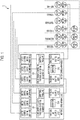
- the motor control system 1 is configured to control a plurality of motors #1 to #6. As illustrated in Fig. 1 , the motor control system 1 includes motor control apparatuses #1 and #2, motors #1 to #6, a mechanical apparatus (not illustrated), encoders #1 to #6, and sensors #7 to #9.
- Each of the motor control apparatuses #1 and #2 is configured to control at least one of the plurality of motors #1 to #6.
- the motor control apparatus #1 is configured to control the motors #1 to #3, and the motor control apparatus #2 is configured to control the motors #4 to #6 is described.
- the present disclosure is not limited to the case.
- the present disclosure can be applied to a case where the motor control apparatus #1 controls the motors #1 to #6.
- the motor control apparatuses #1 and #2 are devices including computers that control amplifier units that output a current, a voltage, and the like to the motors #1 to #3 and the motors #4 to #6, respectively. That is, the motors #1 to #3 and the motors #4 to #6 are configured to rotate in accordance with the voltage or the current applied from the motor control apparatuses #1 and #2, respectively.
- the motor control apparatuses #1 and #2 that control a servomotor are called as servo-controllers, servo-amplifiers, or the like.
- the motor control apparatuses #1 and #2 may be devices configured to control motors, for example, may be inverters.
- the motor control apparatus #1 includes an amplifier unit (not illustrated), motor control units #1 to #3 that respectively control the motors #1 to #3, an encoder-sensor communication transmission-and-reception management unit 10, transmission and reception units #1 and #2, and a repeater 20.
- the motor control apparatus #2 includes an amplifier unit (not illustrated), motor control units #4 to #6 that respectively control the motors #4 to #6, an encoder-sensor communication transmission-and-reception management unit 10, transmission and reception units #1 and #2, and a repeater 20.
- the amplifier unit is a power converter configured to supply a current or a voltage based on a torque command from the motor control units #1 to #6, to the motors #1 to #6.
- each of the motor control apparatuses #1 and #2 includes a motor control calculation unit 101, an encoder logical-axis interface 102, and a sensor logical-axis interface 103.
- the motor control calculation unit 101 is configured to receive a command (position command and the like) from a host device and performs calculation for controlling positions, speeds, torques, and the like of the motors #1 to #6.
- the encoder logical-axis interface 102 is configured to read out at least one of constants of the motors #1 to #6 corresponding to the motor control units #1 to #6 to which the encoder logical-axis interface 102 belongs, and identification information (encoder ID information) of the encoders #1 to #6 corresponding to the motors #1 to #6, based on mapping tables #1 and #2 managed by the encoder-sensor communication transmission-and-reception management units 10 in a constant reading procedure.
- the encoder logical-axis interface 102 is configured to acquire position information of the motors #1 to #6 corresponding to the motor control units #1 to #6 to which the encoder logical-axis interface 102 belongs, based on the mapping tables #1 and #2 managed by the encoder-sensor communication transmission-and-reception management units 10 in a position-information reading procedure.
- the encoder logical-axis interface 102 in the motor control unit #1 is configured to acquire the motor constant or the position information of the motor #1 and the encoder ID information of the encoder #1 from the encoder-sensor communication transmission-and-reception management unit 10.
- the encoder logical-axis interface 102 in the motor control unit #2 is configured to acquire the motor constant or the position information of the motor #2 and the encoder ID information of the encoder #2 from the encoder-sensor communication transmission-and-reception management unit 10.
- the encoder logical-axis interface 102 in the motor control unit #3 is configured to acquire the motor constant or the position information of the motor #3 and the encoder ID information of the encoder #3 from the encoder-sensor communication transmission-and-reception management unit 10.
- the encoder logical-axis interface 102 in the motor control unit #4 is configured to acquire the motor constant or the position information of the motor #4 and the encoder ID information of the encoder #4 from the encoder-sensor communication transmission-and-reception management unit 10.
- the encoder logical-axis interface 102 in the motor control unit #5 is configured to acquire the motor constant or the position information of the motor #5 and the encoder ID information of the encoder #5 from the encoder-sensor communication transmission-and-reception management unit 10.
- the encoder logical-axis interface 102 in the motor control unit #6 is configured to acquire the motor constant or the position information of the motor #6 and the encoder ID information of the encoder #6 from the encoder-sensor communication transmission-and-reception management unit 10.
- the sensor logical-axis interface 103 is configured to read out identification information (sensor ID information) of the sensors #7 to #9 corresponding to the motors #1 to #6 corresponding to the motor control units #1 to #6 to which the sensor logical-axis interface 103 belongs, based on the mapping tables #1 and #2 managed by the encoder-sensor communication transmission-and-reception management units 10 in the constant reading procedure.
- the sensor logical-axis interface 103 is configured to read out sensor data of the sensors #7 to #9 corresponding to the motors #1 to #6 corresponding to the motor control units #1 to #6 to which the sensor logical-axis interface 103 belongs, based on the mapping tables #1 and #2 managed by the encoder-sensor communication transmission-and-reception management units 10 in the position-information reading procedure.
- the sensor data includes ON/OFF information and the like of the sensor, for example.
- the encoder-sensor communication transmission-and-reception management unit 10 is configured to manage communications with the motors #1 to #6 or the sensors #7 to #9.
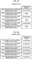
- the encoder-sensor communication transmission-and-reception management unit 10 is configured to manage the mapping tables illustrated in Figs. 3(a) and 3(b) .
- Fig. 3(a) illustrates an example of the mapping table managed by the encoder-sensor communication transmission-and-reception management unit 10 in the motor control apparatus #2 in the embodiment.
- Fig. 3(b) illustrates an example of the mapping table managed by the encoder-sensor communication transmission-and-reception management unit 10 in the motor control apparatus #1 in the embodiment.
- the mapping table illustrated in Fig. 3(a) is set such that mapping between the encoder logical-axis interface 102 and the motor control apparatus #4, and the encoder #4 (communication address of the encoder #4) is performed, mapping between the encoder logical-axis interface 102 and the motor control apparatus #5, and the encoder #5 (communication address of the encoder #5) is performed, and mapping between the encoder logical-axis interface 102 and the motor control apparatus #6, and the encoder #6 (communication address of the encoder #6) is performed.
- the mapping table illustrated in Fig. 3(b) is set such that mapping between the encoder logical-axis interface 102 and the motor control apparatus #1, and the encoder #1 (communication address of the encoder #1) is performed, mapping between the sensor logical-axis interface 103 and the motor control apparatus #1, and the sensor #9 (communication address of the sensor #9) is performed, mapping between the encoder logical-axis interface 102 and the motor control apparatus #2, and the encoder #2 (communication address of the encoder #2) is performed, mapping between the sensor logical-axis interface 103 and the motor control apparatus #2, and the sensor #8 (communication address of the sensor #8) is performed, mapping between the encoder logical-axis interface 102 and the motor control apparatus #3, and the encoder #3 (communication address of the encoder #3) is performed, and mapping between the sensor logical-axis interface 103 and the motor control apparatus #3, and the sensor #7 (communication address of the sensor #7) is performed.
- mapping tables may be set in advance by a user, and the setting details may be preserved in non-volatile memories (not illustrated) of the motor control apparatuses #1 and #2.
- the encoder-sensor communication transmission-and-reception management unit 10 is configured to assign unique communication addresses to the encoders #1 to #6 and the sensors #7 to #9 based on the above-described mapping tables in an communication initialization procedure.
- the encoder-sensor communication transmission-and-reception management unit 10 is configured to transfer the constants of the motors #1 to #6, the identification information of the encoders #1 to #6, or the identification information of the sensors #7 to #9 to the corresponding encoder logical-axis interface 102 or the corresponding sensor logical-axis interface 103, based on the above-described mapping tables in the constant reading procedure.
- the encoder-sensor communication transmission-and-reception management unit 10 is configured to transfer the position information of the motors #1 to #6 or the sensor data of the sensors #7 to #9 to the corresponding encoder logical-axis interface 102 or the corresponding sensor logical-axis interface 103, based on the above-described mapping tables in the position-information reading procedure.
- the transmission and reception units #1 and #2 are configured to perform processing of transmitting and receiving data to and from devices (motor control apparatus, encoder, sensor, and the like) other than the motor control apparatuses #1 and #2 to which the transmission and reception units #1 and #2 belong.
- the repeater 20 is configured to perform transfer processing (repetition processing) of data between the transmission and reception unit #1 and the transmission and reception unit #2.
- the encoders #1 to #6 are position detectors configured to detect position information of one motor of the plurality of motors #1 to #6 respectively corresponding to the encoders #1 to #6.
- the encoders #1 to #6 may be optical encoders or magnetic encoders, for example.
- the encoders #1 to #6 are configured to transmit the position information of the motors #1 to #6 to the motor control apparatuses #1 and #2.
- a case using the encoders #1 to #6 as the position detector is described as an example.
- the present disclosure can be applied to a case using a sensor (for example, resolver) capable of detecting the position information of the motors #1 to #6.
- the encoders #1 to #6 may be linear scales (linear encoders) used in a case where the motors #1 to #6 are linear motors.
- the motors #1 to #6 may be rotary motors or linear motors.
- the above-described position information indicates a rotation angle.
- the above-described position information indicates a linear position.
- the mechanical apparatus is configured to be driven by the motors #1 to #6.
- a robot corresponds to a mechanical apparatus 10A.
- each of the motors #1 to #6 is configured to drive each of the first axis to the sixth axis of a six-axis robot as the mechanical apparatus.
- the sensors #7 to #9 are configured to detect information (sensor data) relating to at least any one of the motors #1 to #3 and the mechanical apparatus configured to be driven by the motors #1 to #3.
- information sensor data
- a temperature sensor, a pressure sensor, a torque sensor, a vibration sensor, a limit switch sensor, a touch sensor, and an I/O device are assumed as the plurality of sensors #7 to #9.
- a case where the three sensors #7 to #9 are provided is described as an example.
- the present disclosure can be applied to a case where any sensor is not provided, a case where one sensor is provided, a case where four sensors or more are provided, and the like.
- a case where the two motor control apparatuses #1 and #2 are connected to each other is described.
- the present disclosure can be applied to a case where three motor control apparatuses or more are connected in series.
- a case where the sensors #7 to #9 are connected in series under a control of the encoders #1 to #6 connected in series under the control of the motor control apparatus #1 is described as an example.
- the present disclosure is not limited to the case and can be applied to a case where a connection order of the encoders #1 to #6 and the sensors #7 to #9 is different from that in the above case.
- the motor control apparatus #1 is configured to transfer the position information of the motors #1 to #6, which has been read out from the encoders #1 to #6, to the motor control apparatus #2 (other motor control apparatus) in the position-information reading procedure.
- the motor control apparatus #1 is configured to read at least one of the motor constants of the motors #1 to #3 and the encoder ID information of the encoders #1 to #3, from the encoders #1 to #3 respectively corresponding to the motors #1 to #3 controlled by the motor control apparatus #1.
- the motor control apparatus #1 is configured to read out the identification information of the sensors #7 to #9 from the sensors #7 to #9 corresponding to the motors #1 to #3 controlled by the motor control apparatus #1.
- the motor control apparatus #2 is configured to read out at least any one of the motor constants of the motors #4 to #6 and the encoder ID information of the encoders #4 to #6, from the encoders #4 to #6 corresponding to the motors #4 to #6 controlled by the motor control apparatus #2, through the motor control apparatus #1.
- the motor control apparatus #2 (one of the other motor control apparatuses) is configured to operate as the master and read out the identification information (sensor ID information) of the sensors #7 to #9 from the sensors #7 to #9 through the motor control apparatus #1, in position-information reading procedure.
- the motor control apparatus #1 is configured to read out the sensor data of the sensors #7 to #9 from the sensors #7 to #9 corresponding to the motors #1 to #3 controlled by the motor control apparatus #1.
- the motor control apparatus #2 is configured to read out the sensor ID information of the sensor from this sensor through the motor control apparatus #1.
- a case where three axes of the six-axis robot are controlled by each of the two motor control apparatuses #1 and #2 is described as an example.
- the present disclosure can be applied to a case of controlling a one-axis robot by one motor control apparatus, a case of controlling two axes of a six-axis robot by each of three motor control apparatuses, a case of controlling three axes of a nine-axis robot by each of three motor control apparatuses, and the like.
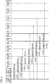
- Fig. 4 illustrates a flow of processing in a communication initialization procedure in the motor control system 1.
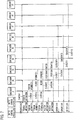
- Figs. 5 and 6 illustrate a flow of processing in the constant reading procedure in the motor control system 1.
- Fig. 7 illustrates a flow of processing in the position-information reading procedure (normal mode) in the motor control system 1.
- the communication initialization procedure in the motor control system 1 will be described with reference to Fig. 4 .
- the motor control apparatus #2 operates as the master, and the motor control apparatus #1 operates as a slave.
- the repeater 20 in the motor control apparatus #1 turns into an ON state.
- Step S1001 the encoder-sensor communication transmission-and-reception management unit 10 in the motor control apparatus #2 assigns an unique communication address to the encoder #1 by transmitting address setting data to the encoder #1 through the transmission and reception unit #2 in the motor control apparatus #2, the transmission and reception unit #1 in the motor control apparatus #1, the repeater 20 in the motor control apparatus #1, and the transmission and reception unit #2 in the motor control apparatus #2.
- Step S1002 the encoder-sensor communication transmission-and-reception management unit 10 in the motor control apparatus #2 assigns an unique communication address to the encoder #2 by transmitting address setting data to the encoder #2 through the transmission and reception unit #2 in the motor control apparatus #2, the transmission and reception unit #1 in the motor control apparatus #1, the repeater 20 in the motor control apparatus #1, the transmission and reception unit #2 in the motor control apparatus #2, and the encoder #1.
- Step S1003 the encoder-sensor communication transmission-and-reception management unit 10 in the motor control apparatus #2 assigns an unique communication address to the encoder #3 by transmitting address setting data to the encoder #3 through the transmission and reception unit #2 in the motor control apparatus #2, the transmission and reception unit #1 in the motor control apparatus #1, the repeater 20 in the motor control apparatus #1, the transmission and reception unit #2 in the motor control apparatus #2, the encoder #1, and the encoder #2.
- Step S1004 the encoder-sensor communication transmission-and-reception management unit 10 in the motor control apparatus #2 assigns an unique communication address to the encoder #4 by transmitting address setting data to the encoder #4 through the transmission and reception unit #2 in the motor control apparatus #2, the transmission and reception unit #1 in the motor control apparatus #1, the repeater 20 in the motor control apparatus #1, the transmission and reception unit #2 in the motor control apparatus #2, the encoder #1, the encoder #2, and the encoder #3.
- Step S1005 the encoder-sensor communication transmission-and-reception management unit 10 in the motor control apparatus #2 assigns an unique communication address to the encoder #5 by transmitting address setting data to the encoder #5 through the transmission and reception unit #2 in the motor control apparatus #2, the transmission and reception unit #1 in the motor control apparatus #1, the repeater 20 in the motor control apparatus #1, the transmission and reception unit #2 in the motor control apparatus #2, the encoder #1, the encoder #2, the encoder #3, and the encoder #4.
- Step S1006 the encoder-sensor communication transmission-and-reception management unit 10 in the motor control apparatus #2 assigns an unique communication address to the encoder #6 by transmitting address setting data to the encoder #6 through the transmission and reception unit #2 in the motor control apparatus #2, the transmission and reception unit #1 in the motor control apparatus #1, the repeater 20 in the motor control apparatus #1, the transmission and reception unit #2 in the motor control apparatus #2, the encoder #1, the encoder #2, the encoder #3, the encoder #4, and the encoder #5.
- Step S1007 the encoder-sensor communication transmission-and-reception management unit 10 in the motor control apparatus #2 assigns an unique communication address to the sensor #7 by transmitting address setting data to the sensor #7 through the transmission and reception unit #2 in the motor control apparatus #2, the transmission and reception unit #1 in the motor control apparatus #1, the repeater 20 in the motor control apparatus #1, the transmission and reception unit #2 in the motor control apparatus #2, the encoder #1, the encoder #2, the encoder #3, the encoder #4, the encoder #5, and the encoder #6.
- Step S1008 the encoder-sensor communication transmission-and-reception management unit 10 in the motor control apparatus #2 assigns an unique communication address to the sensor #8 by transmitting address setting data to the sensor #8 through the transmission and reception unit #2 in the motor control apparatus #2, the transmission and reception unit #1 in the motor control apparatus #1, the repeater 20 in the motor control apparatus #1, the transmission and reception unit #2 in the motor control apparatus #2, the encoder #1, the encoder #2, the encoder #3, the encoder #4, the encoder #5, the encoder #6, and the sensor #7.
- the encoder-sensor communication transmission-and-reception management unit 10 in the motor control apparatus #2 assigns an unique communication address to the sensor #9 by transmitting address setting data to the sensor #9 through the transmission and reception unit #2 in the motor control apparatus #2, the transmission and reception unit #1 in the motor control apparatus #1, the repeater 20 in the motor control apparatus #1, the transmission and reception unit #2 in the motor control apparatus #2, the encoder #1, the encoder #2, the encoder #3, the encoder #4, the encoder #5, the encoder #6, the sensor #7, and the sensor #8.
- the motor control unit #4 in the motor control apparatus #2 transmits an ID/constant reading request to the encoder #4 through the encoder-sensor communication transmission-and-reception management unit 10 in the motor control apparatus #2, the transmission and reception unit #2 in the motor control apparatus #2, the transmission and reception unit #1 in the motor control apparatus #1, the repeater 20 in the motor control apparatus #1, and the transmission and reception unit #2 in the motor control apparatus #2.
- the encoder #4 transmits ID/constant reading data (motor constant of the motor #4 or encoder ID information of the encoder #4) to the motor control unit #4 in the motor control apparatus #2 through the transmission and reception unit #2 in the motor control apparatus #2, the repeater 20 in the motor control apparatus #1, the transmission and reception unit #1 in the motor control apparatus #1, the transmission and reception unit #2 in the motor control apparatus #2, and the encoder-sensor communication transmission-and-reception management unit 10 in the motor control apparatus #2.
- ID/constant reading data motor constant of the motor #4 or encoder ID information of the encoder #4
- Step S2003 the motor control unit #5 in the motor control apparatus #2 transmits an ID/constant reading request to the encoder #5 through the encoder-sensor communication transmission-and-reception management unit 10 in the motor control apparatus #2, the transmission and reception unit #2 in the motor control apparatus #2, the transmission and reception unit #1 in the motor control apparatus #1, the repeater 20 in the motor control apparatus #1, the transmission and reception unit #2 in the motor control apparatus #2, and the encoder #4.
- the encoder #5 transmits ID/constant reading data (motor constant of the motor #5 or encoder ID information of the encoder #5) to the motor control unit #5 in the motor control apparatus #2 through the encoder #4, the transmission and reception unit #2 in the motor control apparatus #2, the repeater 20 in the motor control apparatus #1, the transmission and reception unit #1 in the motor control apparatus #1, the transmission and reception unit #2 in the motor control apparatus #2, and the encoder-sensor communication transmission-and-reception management unit 10 in the motor control apparatus #2.
- ID/constant reading data motor constant of the motor #5 or encoder ID information of the encoder #5
- Step S2005 the motor control unit #6 in the motor control apparatus #2 transmits an ID/constant reading request to the encoder #6 through the encoder-sensor communication transmission-and-reception management unit 10 in the motor control apparatus #2, the transmission and reception unit #2 in the motor control apparatus #2, the transmission and reception unit #1 in the motor control apparatus #1, the repeater 20 in the motor control apparatus #1, the transmission and reception unit #2 in the motor control apparatus #2, the encoder #4, and the encoder #5.
- the encoder #6 transmits ID/constant reading data (motor constant of the motor #6 or encoder ID information of the encoder #6) to the motor control unit #6 in the motor control apparatus #2 through the encoder #5, the encoder #4, the transmission and reception unit #2 in the motor control apparatus #2, the repeater 20 in the motor control apparatus #1, the transmission and reception unit #1 in the motor control apparatus #1, the transmission and reception unit #2 in the motor control apparatus #2, and the encoder-sensor communication transmission-and-reception management unit 10 in the motor control apparatus #2.
- Step S3001 the motor control unit #1 in the motor control apparatus #1 transmits an ID/constant reading request to the encoder #1 through the encoder-sensor communication transmission-and-reception management unit 10 in the motor control apparatus #1 and the transmission and reception unit #2 in the motor control apparatus #1.
- the encoder #1 transmits ID/constant reading data (motor constant of the motor #1 or encoder ID information of the encoder #1) to the motor control unit #1 in the motor control apparatus #1 through the transmission and reception unit #2 in the motor control apparatus #1 and the encoder-sensor communication transmission-and-reception management unit 10 in the motor control apparatus #1.
- ID/constant reading data motor constant of the motor #1 or encoder ID information of the encoder #1
- Step S3003 the motor control unit #2 in the motor control apparatus #1 transmits an ID/constant reading request to the encoder #2 through the encoder-sensor communication transmission-and-reception management unit 10 in the motor control apparatus #1, the transmission and reception unit #2 in the motor control apparatus #1, and the encoder #1.
- Step S3004 the encoder #2 transmits ID/constant reading data (motor constant of the motor #2 or encoder ID information of the encoder #2) to the motor control unit #2 in the motor control apparatus #1 through the encoder #1, the transmission and reception unit #2 in the motor control apparatus #1, and the encoder-sensor communication transmission-and-reception management unit 10 in the motor control apparatus #1.
- ID/constant reading data motor constant of the motor #2 or encoder ID information of the encoder #2
- Step S3005 the motor control unit #3 in the motor control apparatus #1 transmits an ID/constant reading request to the encoder #3 through the encoder-sensor communication transmission-and-reception management unit 10 in the motor control apparatus #1, the transmission and reception unit #2 in the motor control apparatus #1, the encoder #1, and the encoder #2.
- the encoder #3 transmits ID/constant reading data (motor constant of the motor #3 or encoder ID information of the encoder #3) to the motor control unit #3 in the motor control apparatus #1 through the encoder #2, the encoder #1, the transmission and reception unit #2 in the motor control apparatus #1, and the encoder-sensor communication transmission-and-reception management unit 10 in the motor control apparatus #1.
- Step S3007 the motor control unit #3 in the motor control apparatus #1 transmits an ID/constant reading request to the sensor #7 through the encoder-sensor communication transmission-and-reception management unit 10 in the motor control apparatus #1, the transmission and reception unit #2 in the motor control apparatus #1, the encoder #1, the encoder #2, the encoder #3, the encoder #4, the encoder #5, and the encoder #6.
- the sensor #7 transmits ID/constant reading data (sensor ID information of the sensor #7) to the motor control unit #3 in the motor control apparatus #1 through the encoder #6, the encoder #5, the encoder #4, the encoder #3, the encoder #2, the encoder #1, the transmission and reception unit #2 in the motor control apparatus #1, and the encoder-sensor communication transmission-and-reception management unit 10 in the motor control apparatus #1.
- Step S3009 the motor control unit #2 in the motor control apparatus #1 transmits an ID/constant reading request to the sensor #8 through the encoder-sensor communication transmission-and-reception management unit 10 in the motor control apparatus #1, the transmission and reception unit #2 in the motor control apparatus #1, the encoder #1, the encoder #2, the encoder #3, the encoder #4, the encoder #5, the encoder #6, and the sensor #7.
- the sensor #8 transmits ID/constant reading data (sensor ID information of the sensor #8) to the motor control unit #2 in the motor control apparatus #1 through the sensor #7, the encoder #6, the encoder #5, the encoder #4, the encoder #3, the encoder #2, the encoder #1, the transmission and reception unit #2 in the motor control apparatus #1, and the encoder-sensor communication transmission-and-reception management unit 10 in the motor control apparatus #1.
- Step S3011 the motor control unit #1 in the motor control apparatus #1 transmits an ID/constant reading request to the sensor #9 through the encoder-sensor communication transmission-and-reception management unit 10 in the motor control apparatus #1, the transmission and reception unit #2 in the motor control apparatus #1, the encoder #1, the encoder #2, the encoder #3, the encoder #4, the encoder #5, the encoder #6, the sensor #7, and the sensor #8.
- the sensor #9 transmits ID/constant reading data (sensor ID information of the sensor #9) to the motor control unit #1 in the motor control apparatus #1 through the sensor #8, the sensor #7, the encoder #6, the encoder #5, the encoder #4, the encoder #3, the encoder #2, the encoder #1, the transmission and reception unit #2 in the motor control apparatus #1, and the encoder-sensor communication transmission-and-reception management unit 10 in the motor control apparatus #1.
- the motor control apparatus #1 operates as the master. Before the processing is started, the transmission and reception unit #1 in the motor control apparatus #1 is stopped, and the repeater 20 in the motor control apparatus #1 turns into the OFF state. The motor control apparatus #2 is in a state of waiting for receiving the position information of the motors #4 to #6, in this period (until the motor control apparatus #1 completes the entirety of the constant reading procedure).
- the position-information reading procedure (normal mode) in the motor control system 1 will be described with reference to Fig. 7 .
- the motor control apparatus #2 operates as the master.
- the motor control apparatus #1 turns into a monitoring mode in which only monitoring data transmitted from the motor control apparatus #2, the encoders #1 to #6, or the sensors #7 to #9 is possible.
- the repeater 20 in the motor control apparatus #1 turns into the ON state.
- Step S4001 the encoder-sensor communication transmission-and-reception management unit 10 in the motor control apparatus #2 broadcasts a position information acquisition request to the encoders #1 to #6 and the sensors #7 to #9 through the transmission and reception unit #2 in the motor control apparatus #2, the transmission and reception unit #1 in the motor control apparatus #1, the repeater 20 in the motor control apparatus #1, and the transmission and reception unit #2 in the motor control apparatus #1.
- the encoder #1 transmits the position information of the motor #1 to the motor control unit #1 through the transmission and reception unit #2 in the motor control apparatus #1, the repeater 20 in the motor control apparatus #1, the transmission and reception unit #1 in the motor control apparatus #1, the transmission and reception unit #2 in the motor control apparatus #2, and the encoder-sensor communication transmission-and-reception management unit 10 in the motor control apparatus #2.
- the motor control apparatus #1 takes the position information of the encoder #1 with reference to the mapping table #1 (see Fig. 3(b) ) managed by the encoder-sensor communication transmission-and-reception management unit 10 in the motor control apparatus #1.
- the encoder #2 transmits the position information of the motor #2 to the motor control unit #2 through the encoder #1, the transmission and reception unit #2 in the motor control apparatus #1, the repeater 20 in the motor control apparatus #1, the transmission and reception unit #1 in the motor control apparatus #1, the transmission and reception unit #2 in the motor control apparatus #2, and the encoder-sensor communication transmission-and-reception management unit 10 in the motor control apparatus #2.
- the motor control apparatus #1 takes the position information of the encoder #2 with reference to the mapping table #1 (see Fig. 3(b) ) managed by the encoder-sensor communication transmission-and-reception management unit 10 in the motor control apparatus #1.
- the encoder #3 transmits the position information of the motor #3 to the motor control unit #3 through the encoder #2, the encoder #1, the transmission and reception unit #2 in the motor control apparatus #1, the repeater 20 in the motor control apparatus #1, the transmission and reception unit #1 in the motor control apparatus #1, the transmission and reception unit #2 in the motor control apparatus #2, and the encoder-sensor communication transmission-and-reception management unit 10 in the motor control apparatus #2.
- the motor control apparatus #1 takes the position information of the encoder #3 with reference to the mapping table #1 (see Fig. 3(b) ) managed by the encoder-sensor communication transmission-and-reception management unit 10 in the motor control apparatus #1.
- Step S4005 the encoder #4 transmits the position information of the motor #4 to the motor control unit #4 through the encoder #3, the encoder #2, the encoder #1, the transmission and reception unit #2 in the motor control apparatus #1, the repeater 20 in the motor control apparatus #1, the transmission and reception unit #1 in the motor control apparatus #1, the transmission and reception unit #2 in the motor control apparatus #2, and the encoder-sensor communication transmission-and-reception management unit 10 in the motor control apparatus #2.
- the encoder #5 transmits the position information of the motor #5 to the motor control unit #5 through the encoder #4, the encoder #3, the encoder #2, the encoder #1, the transmission and reception unit #2 in the motor control apparatus #1, the repeater 20 in the motor control apparatus #1, the transmission and reception unit #1 in the motor control apparatus #1, the transmission and reception unit #2 in the motor control apparatus #2, and the encoder-sensor communication transmission-and-reception management unit 10 in the motor control apparatus #2.
- the encoder #6 transmits the position information of the motor #6 to the motor control unit #6 through the encoder #5, the encoder #4, the encoder #3, the encoder #2, the encoder #1, the transmission and reception unit #2 in the motor control apparatus #1, the repeater 20 in the motor control apparatus #1, the transmission and reception unit #1 in the motor control apparatus #1, the transmission and reception unit #2 in the motor control apparatus #2, and the encoder-sensor communication transmission-and-reception management unit 10 in the motor control apparatus #2.
- the sensor #7 transmits the sensor data of the sensor #7 to the motor control unit #3 through the encoder #6, the encoder #5, the encoder #4, the encoder #3, the encoder #2, the encoder #1, the transmission and reception unit #2 in the motor control apparatus #1, the repeater 20 in the motor control apparatus #1, the transmission and reception unit #1 in the motor control apparatus #1, the transmission and reception unit #2 in the motor control apparatus #2, and the encoder-sensor communication transmission-and-reception management unit 10 in the motor control apparatus #2.
- the sensor #8 transmits the sensor data of the sensor #8 to the motor control unit #2 through the sensor #7, the encoder #6, the encoder #5, the encoder #4, the encoder #3, the encoder #2, the encoder #1, the transmission and reception unit #2 in the motor control apparatus #1, the repeater 20 in the motor control apparatus #1, the transmission and reception unit #1 in the motor control apparatus #1, the transmission and reception unit #2 in the motor control apparatus #2, and the encoder-sensor communication transmission-and-reception management unit 10 in the motor control apparatus #2.
- the sensor #9 transmits the sensor data of the sensor #9 to the motor control unit #1 through the sensor #8, the sensor #7, the encoder #6, the encoder #5, the encoder #4, the encoder #3, the encoder #2, the encoder #1, the transmission and reception unit #2 in the motor control apparatus #1, the repeater 20 in the motor control apparatus #1, the transmission and reception unit #1 in the motor control apparatus #1, the transmission and reception unit #2 in the motor control apparatus #2, and the encoder-sensor communication transmission-and-reception management unit 10 in the motor control apparatus #2.
- the motor control system 1 in the embodiment even in a case where the plurality of encoders are connected in series under the control of the motor control unit #1 in the motor control apparatus 20, and the motor control unit #1 and the motor control unit #2 are connected to each other, it is possible to appropriately realize the setting procedure of the motor control apparatus 20. As a result, it is possible to reduce a physical or processing cost.
- the number of wires between the encoders #1 to #6 (and the mechanical apparatus that is driven by the motors #1 to #6), and the motor control apparatuses #1 and #2 installed in a control board is reduced.
Landscapes
- Engineering & Computer Science (AREA)
- Power Engineering (AREA)
- Human Computer Interaction (AREA)
- Manufacturing & Machinery (AREA)
- Physics & Mathematics (AREA)
- General Physics & Mathematics (AREA)
- Automation & Control Theory (AREA)
- Control Of Multiple Motors (AREA)
Abstract
Description
- The present disclosure relates to a motor control system, a control method, and a motor control apparatus.
-
Patent Literature 1 discloses a system in which a plurality of sensors are connected to an interface unit through respective communication paths, and a detection signal of each of the sensors is transmitted to a host controller or a motor control apparatus via a network that connects the host controller and the motor control apparatus to each other. -
Patent Literature 2 discloses a system in which a peripheral device that sets a parameter of a motor control apparatus or performs monitoring of the motor control apparatus through a communication unit in the motor control apparatus is connected. -
- Patent Literature 1:
JP H8-241111 A - Patent Literature 2:
JP H10-105206 A - However, there is a problem in that each sensor or each peripheral device is connected to a motor control apparatus, and thus a physical or processing cost tends to increase, in the system in the related art.
- The present disclosure has been made in consideration of the above circumstances, and an object of the present disclosure is to provide a motor control system, a control method, and a motor control apparatus, in which it is possible to reduce a physical or processing cost.
- The first aspect of the present disclosure is summarized as a motor control system configured to control a plurality of motors, the system including: a plurality of motor control apparatuses, each being configured to control at least one of the plurality of motors; and a plurality of position detectors configured to detect position information of one motor corresponding to each of the position detectors among the plurality of motors, wherein all of the plurality of position detectors are configured to be connected in series under a control of a first motor control apparatus in the plurality of motor control apparatuses, and the first motor control apparatus is configured to transfer the position information of the plurality of motors read out from the plurality of position detectors to other motor control apparatuses in the plurality of motor control apparatuses.
- The second aspect of the present disclosure is summarized as a control method in a motor control system configured to control a plurality of motors, the method including: controlling at least one of the plurality of motors by each of a plurality of motor control apparatuses; detecting position information of one of the plurality of motors, which corresponding to each of a plurality of position detectors by each of the plurality of position detectors; and transferring position information of the plurality of motors to other motor control apparatuses in the plurality of motor control apparatuses by a first motor control apparatus in the plurality of motor control apparatuses, the position information being read out from all of the plurality of position detectors, and all of the plurality of position detectors being connected in series under a control of the first motor control apparatus.
- The third aspect of the present disclosure is summarized as a motor control apparatus used in a motor control system configured to control a plurality of motors, wherein the motor control apparatus is configured to control at least one of the plurality of motors, a plurality of position detectors configured to detect position information of one motor corresponding to each of the position detectors among the plurality of motors are connected in series under a control of the motor control apparatus, and the motor control apparatus is configured to transfer position information of the plurality of motors to other motor control apparatuses, the position information being read out from the plurality of position detectors.
- According to the present disclosure, it is possible to provide a motor control system, a control method, and a motor control apparatus, in which it is possible to reduce a physical or processing cost.
-
-
Fig. 1 is a schematic diagram illustrating an example of an overall configuration of a motor control system according to an embodiment. -
Fig. 2 is a diagram illustrating an example of a function block of a motor control unit in each of motor control apparatuses constituting a motor control system according to the embodiment. -
Fig. 3 is a diagram illustrating an example of a mapping table managed by an encoder-sensor communication transmission-and-reception management unit of each of the motor control apparatuses constituting the motor control system according to the embodiment. -
Fig. 4 is a diagram illustrating an example of a flow of processing performed in the motor control system according to the embodiment. -
Fig. 5 is a diagram illustrating an example of a flow of processing performed in the motor control system according to the embodiment. -
Fig. 6 is a diagram illustrating another example of the flow of the processing performed in the motor control system according to the embodiment. -
Fig. 7 is a diagram illustrating an example of a flow of processing performed in the motor control system according to the embodiment. - According to the viewpoint of the inventor of the present invention, sensing of an operation situation in a motor control system has become more important in recent years. However, if the number of sensors increases, a physical cost for the number of wires and the like and a processing cost for traffic, processing loads, and the like increase. In particular, in a case where sensing is performed in real time, the costs tend to increase.
- As a result of intensive research and development to reduce the costs in the motor control system, the inventor of the present invention has conceived of a new and unique motor control system. Hereinafter, an example of a
motor control system 1 according to an embodiment will be described with reference toFigs. 1 to 7 . - In the present disclosure, the
motor control system 1 according to the embodiment is configured to control a plurality ofmotors # 1 to #6. As illustrated inFig. 1 , themotor control system 1 includes motorcontrol apparatuses # 1 and #2,motors # 1 to #6, a mechanical apparatus (not illustrated),encoders # 1 to #6, andsensors # 7 to #9. - Each of the motor
control apparatuses # 1 and #2 is configured to control at least one of the plurality ofmotors # 1 to #6. - In the embodiment, as an example, a case where the motor
control apparatus # 1 is configured to control themotors # 1 to #3, and the motorcontrol apparatus # 2 is configured to control themotors # 4 to #6 is described. The present disclosure is not limited to the case. For example, the present disclosure can be applied to a case where the motorcontrol apparatus # 1 controls themotors # 1 to #6. - In the embodiment, a case where the two motor
control apparatuses # 1 and #2 are provided is described as an example. The present disclosure can be applied to a case where three motor control apparatuses or more are provided. - Specifically, the motor
control apparatuses # 1 and #2 are devices including computers that control amplifier units that output a current, a voltage, and the like to themotors # 1 to #3 and themotors # 4 to #6, respectively. That is, themotors # 1 to #3 and themotors # 4 to #6 are configured to rotate in accordance with the voltage or the current applied from the motorcontrol apparatuses # 1 and #2, respectively. - Generally, the motor
control apparatuses # 1 and #2 that control a servomotor are called as servo-controllers, servo-amplifiers, or the like. The motorcontrol apparatuses # 1 and #2 may be devices configured to control motors, for example, may be inverters. - Specifically, as illustrated in
Fig. 1 , the motorcontrol apparatus # 1 includes an amplifier unit (not illustrated), motorcontrol units # 1 to #3 that respectively control themotors # 1 to #3, an encoder-sensor communication transmission-and-reception management unit 10, transmission andreception units # 1 and #2, and arepeater 20. - Similarly, the motor
control apparatus # 2 includes an amplifier unit (not illustrated), motorcontrol units # 4 to #6 that respectively control themotors # 4 to #6, an encoder-sensor communication transmission-and-reception management unit 10, transmission andreception units # 1 and #2, and arepeater 20. - The amplifier unit is a power converter configured to supply a current or a voltage based on a torque command from the motor
control units # 1 to #6, to themotors # 1 to #6. - Here, as illustrated in
Fig. 2 , each of the motorcontrol apparatuses # 1 and #2 includes a motorcontrol calculation unit 101, an encoder logical-axis interface 102, and a sensor logical-axis interface 103. - The motor
control calculation unit 101 is configured to receive a command (position command and the like) from a host device and performs calculation for controlling positions, speeds, torques, and the like of themotors # 1 to #6. - The encoder logical-
axis interface 102 is configured to read out at least one of constants of themotors # 1 to #6 corresponding to the motorcontrol units # 1 to #6 to which the encoder logical-axis interface 102 belongs, and identification information (encoder ID information) of theencoders # 1 to #6 corresponding to themotors # 1 to #6, based onmapping tables # 1 and #2 managed by the encoder-sensor communication transmission-and-reception management units 10 in a constant reading procedure. - The encoder logical-
axis interface 102 is configured to acquire position information of themotors # 1 to #6 corresponding to the motorcontrol units # 1 to #6 to which the encoder logical-axis interface 102 belongs, based on themapping tables # 1 and #2 managed by the encoder-sensor communication transmission-and-reception management units 10 in a position-information reading procedure. - Specifically, in the embodiment, the encoder logical-
axis interface 102 in the motorcontrol unit # 1 is configured to acquire the motor constant or the position information of themotor # 1 and the encoder ID information of theencoder # 1 from the encoder-sensor communication transmission-and-reception management unit 10. - Similarly, the encoder logical-
axis interface 102 in the motorcontrol unit # 2 is configured to acquire the motor constant or the position information of themotor # 2 and the encoder ID information of theencoder # 2 from the encoder-sensor communication transmission-and-reception management unit 10. - Similarly, the encoder logical-
axis interface 102 in the motorcontrol unit # 3 is configured to acquire the motor constant or the position information of themotor # 3 and the encoder ID information of theencoder # 3 from the encoder-sensor communication transmission-and-reception management unit 10. - Similarly, the encoder logical-
axis interface 102 in the motorcontrol unit # 4 is configured to acquire the motor constant or the position information of themotor # 4 and the encoder ID information of theencoder # 4 from the encoder-sensor communication transmission-and-reception management unit 10. - Similarly, the encoder logical-
axis interface 102 in the motorcontrol unit # 5 is configured to acquire the motor constant or the position information of themotor # 5 and the encoder ID information of theencoder # 5 from the encoder-sensor communication transmission-and-reception management unit 10. - Similarly, the encoder logical-
axis interface 102 in the motorcontrol unit # 6 is configured to acquire the motor constant or the position information of themotor # 6 and the encoder ID information of theencoder # 6 from the encoder-sensor communication transmission-and-reception management unit 10. - The sensor logical-
axis interface 103 is configured to read out identification information (sensor ID information) of thesensors # 7 to #9 corresponding to themotors # 1 to #6 corresponding to the motorcontrol units # 1 to #6 to which the sensor logical-axis interface 103 belongs, based on themapping tables # 1 and #2 managed by the encoder-sensor communication transmission-and-reception management units 10 in the constant reading procedure. - The sensor logical-
axis interface 103 is configured to read out sensor data of thesensors # 7 to #9 corresponding to themotors # 1 to #6 corresponding to the motorcontrol units # 1 to #6 to which the sensor logical-axis interface 103 belongs, based on themapping tables # 1 and #2 managed by the encoder-sensor communication transmission-and-reception management units 10 in the position-information reading procedure. Here, the sensor data includes ON/OFF information and the like of the sensor, for example. - The encoder-sensor communication transmission-and-
reception management unit 10 is configured to manage communications with themotors # 1 to #6 or thesensors # 7 to #9. Here, the encoder-sensor communication transmission-and-reception management unit 10 is configured to manage the mapping tables illustrated inFigs. 3(a) and 3(b) . -
Fig. 3(a) illustrates an example of the mapping table managed by the encoder-sensor communication transmission-and-reception management unit 10 in the motorcontrol apparatus # 2 in the embodiment.Fig. 3(b) illustrates an example of the mapping table managed by the encoder-sensor communication transmission-and-reception management unit 10 in the motorcontrol apparatus # 1 in the embodiment. - The mapping table illustrated in
Fig. 3(a) is set such that mapping between the encoder logical-axis interface 102 and the motorcontrol apparatus # 4, and the encoder #4 (communication address of the encoder #4) is performed, mapping between the encoder logical-axis interface 102 and the motorcontrol apparatus # 5, and the encoder #5 (communication address of the encoder #5) is performed, and mapping between the encoder logical-axis interface 102 and the motorcontrol apparatus # 6, and the encoder #6 (communication address of the encoder #6) is performed. - The mapping table illustrated in
Fig. 3(b) is set such that mapping between the encoder logical-axis interface 102 and the motorcontrol apparatus # 1, and the encoder #1 (communication address of the encoder #1) is performed, mapping between the sensor logical-axis interface 103 and the motorcontrol apparatus # 1, and the sensor #9 (communication address of the sensor #9) is performed, mapping between the encoder logical-axis interface 102 and the motorcontrol apparatus # 2, and the encoder #2 (communication address of the encoder #2) is performed, mapping between the sensor logical-axis interface 103 and the motorcontrol apparatus # 2, and the sensor #8 (communication address of the sensor #8) is performed, mapping between the encoder logical-axis interface 102 and the motorcontrol apparatus # 3, and the encoder #3 (communication address of the encoder #3) is performed, and mapping between the sensor logical-axis interface 103 and the motorcontrol apparatus # 3, and the sensor #7 (communication address of the sensor #7) is performed. - The mapping tables may be set in advance by a user, and the setting details may be preserved in non-volatile memories (not illustrated) of the motor
control apparatuses # 1 and #2. - For example, the encoder-sensor communication transmission-and-
reception management unit 10 is configured to assign unique communication addresses to theencoders # 1 to #6 and thesensors # 7 to #9 based on the above-described mapping tables in an communication initialization procedure. - The encoder-sensor communication transmission-and-
reception management unit 10 is configured to transfer the constants of themotors # 1 to #6, the identification information of theencoders # 1 to #6, or the identification information of thesensors # 7 to #9 to the corresponding encoder logical-axis interface 102 or the corresponding sensor logical-axis interface 103, based on the above-described mapping tables in the constant reading procedure. - Similarly, the encoder-sensor communication transmission-and-
reception management unit 10 is configured to transfer the position information of themotors # 1 to #6 or the sensor data of thesensors # 7 to #9 to the corresponding encoder logical-axis interface 102 or the corresponding sensor logical-axis interface 103, based on the above-described mapping tables in the position-information reading procedure. - The transmission and
reception units # 1 and #2 are configured to perform processing of transmitting and receiving data to and from devices (motor control apparatus, encoder, sensor, and the like) other than the motorcontrol apparatuses # 1 and #2 to which the transmission andreception units # 1 and #2 belong. - The
repeater 20 is configured to perform transfer processing (repetition processing) of data between the transmission andreception unit # 1 and the transmission andreception unit # 2. - Here, in a connection state of the motor
control apparatuses # 1 and #2 illustrated inFig. 1 , the transmission andreception unit # 1 in the motorcontrol apparatus # 2 is stopped, and therepeater 20 in the motorcontrol apparatus # 2 is in an OFF state. Theencoders # 1 to #6 are position detectors configured to detect position information of one motor of the plurality ofmotors # 1 to #6 respectively corresponding to theencoders # 1 to #6. - Here, the
encoders # 1 to #6 may be optical encoders or magnetic encoders, for example. Theencoders # 1 to #6 are configured to transmit the position information of themotors # 1 to #6 to the motorcontrol apparatuses # 1 and #2. - In the embodiment, a case using the
encoders # 1 to #6 as the position detector is described as an example. The present disclosure can be applied to a case using a sensor (for example, resolver) capable of detecting the position information of themotors # 1 to #6. Here, theencoders # 1 to #6 may be linear scales (linear encoders) used in a case where themotors # 1 to #6 are linear motors. - The
motors # 1 to #6 may be rotary motors or linear motors. Here, in a case where themotors # 1 to #6 are rotary motors, the above-described position information indicates a rotation angle. In a case where themotors # 1 to #6 are linear motors, the above-described position information indicates a linear position. - In the embodiment, a case where the six
encoders # 1 to #6 are provided is described as an example. The present disclosure can be applied to cases where five encoders or less are provided, or seven encoders or more are provided. - The mechanical apparatus is configured to be driven by the
motors # 1 to #6. For example, a robot corresponds to a mechanical apparatus 10A. For example, in the embodiment, each of themotors # 1 to #6 is configured to drive each of the first axis to the sixth axis of a six-axis robot as the mechanical apparatus. - The
sensors # 7 to #9 are configured to detect information (sensor data) relating to at least any one of themotors # 1 to #3 and the mechanical apparatus configured to be driven by themotors # 1 to #3. For example, a temperature sensor, a pressure sensor, a torque sensor, a vibration sensor, a limit switch sensor, a touch sensor, and an I/O device are assumed as the plurality ofsensors # 7 to #9. - In the embodiment, a case where the three
sensors # 7 to #9 are provided is described as an example. The present disclosure can be applied to a case where any sensor is not provided, a case where one sensor is provided, a case where four sensors or more are provided, and the like. - Here, in the
motor control system 1 according to the embodiment, as illustrated inFig. 1 , a case where the two motorcontrol apparatuses # 1 and #2 are connected to each other is described. The present disclosure can be applied to a case where three motor control apparatuses or more are connected in series. - In the
motor control system 1 according to the embodiment, as illustrated inFig. 1 , all of the plurality ofencoders # 1 to #6 are connected in series under a control of the motor control apparatus #1 (first motor control apparatus). - Further, in the
motor control system 1 according to the embodiment, as illustrated inFig. 1 , in a case where thesensors # 7 to #9 are provided, all of theencoders # 1 to #6 and all of thesensors # 7 to #9 are configured to be connected in series under the control of the motorcontrol apparatus # 1. - In the embodiment, a case where the
sensors # 7 to #9 are connected in series under a control of theencoders # 1 to #6 connected in series under the control of the motorcontrol apparatus # 1 is described as an example. The present disclosure is not limited to the case and can be applied to a case where a connection order of theencoders # 1 to #6 and thesensors # 7 to #9 is different from that in the above case. - Here, in the embodiment, the motor
control apparatus # 1 is configured to transfer the position information of themotors # 1 to #6, which has been read out from theencoders # 1 to #6, to the motor control apparatus #2 (other motor control apparatus) in the position-information reading procedure. - In the embodiment, the motor
control apparatus # 1 is configured to read at least one of the motor constants of themotors # 1 to #3 and the encoder ID information of theencoders # 1 to #3, from theencoders # 1 to #3 respectively corresponding to themotors # 1 to #3 controlled by the motorcontrol apparatus # 1. - Similarly, in the embodiment, the motor
control apparatus # 1 is configured to read out the identification information of thesensors # 7 to #9 from thesensors # 7 to #9 corresponding to themotors # 1 to #3 controlled by the motorcontrol apparatus # 1. - In the embodiment, the motor
control apparatus # 2 is configured to read out at least any one of the motor constants of themotors # 4 to #6 and the encoder ID information of theencoders # 4 to #6, from theencoders # 4 to #6 corresponding to themotors # 4 to #6 controlled by the motorcontrol apparatus # 2, through the motorcontrol apparatus # 1. - In the embodiment, the motor control apparatus #2 (one of the other motor control apparatuses) is configured to operate as the master and read out the identification information (sensor ID information) of the
sensors # 7 to #9 from thesensors # 7 to #9 through the motorcontrol apparatus # 1, in position-information reading procedure. - In the embodiment, the motor
control apparatus # 1 is configured to read out the sensor data of thesensors # 7 to #9 from thesensors # 7 to #9 corresponding to themotors # 1 to #3 controlled by the motorcontrol apparatus # 1. - In a case where sensors corresponding to the
motors # 4 to #6 controlled by the motorcontrol apparatus # 2 are provided, the motorcontrol apparatus # 2 is configured to read out the sensor ID information of the sensor from this sensor through the motorcontrol apparatus # 1. - In the embodiment, a case where three axes of the six-axis robot are controlled by each of the two motor
control apparatuses # 1 and #2 is described as an example. The present disclosure can be applied to a case of controlling a one-axis robot by one motor control apparatus, a case of controlling two axes of a six-axis robot by each of three motor control apparatuses, a case of controlling three axes of a nine-axis robot by each of three motor control apparatuses, and the like. - An example of a flow of processing performed in the
motor control system 1 according to the embodiment will be described below with reference toFigs. 4 to 7 .Fig. 4 illustrates a flow of processing in a communication initialization procedure in themotor control system 1.Figs. 5 and6 illustrate a flow of processing in the constant reading procedure in themotor control system 1.Fig. 7 illustrates a flow of processing in the position-information reading procedure (normal mode) in themotor control system 1. - First, the communication initialization procedure in the
motor control system 1 will be described with reference toFig. 4 . When the communication initialization procedure is started, the motorcontrol apparatus # 2 operates as the master, and the motorcontrol apparatus # 1 operates as a slave. Therepeater 20 in the motorcontrol apparatus # 1 turns into an ON state. - As illustrated in
Fig. 4 , in Step S1001, the encoder-sensor communication transmission-and-reception management unit 10 in the motorcontrol apparatus # 2 assigns an unique communication address to theencoder # 1 by transmitting address setting data to theencoder # 1 through the transmission andreception unit # 2 in the motorcontrol apparatus # 2, the transmission andreception unit # 1 in the motorcontrol apparatus # 1, therepeater 20 in the motorcontrol apparatus # 1, and the transmission andreception unit # 2 in the motorcontrol apparatus # 2. - In Step S1002, the encoder-sensor communication transmission-and-
reception management unit 10 in the motorcontrol apparatus # 2 assigns an unique communication address to theencoder # 2 by transmitting address setting data to theencoder # 2 through the transmission andreception unit # 2 in the motorcontrol apparatus # 2, the transmission andreception unit # 1 in the motorcontrol apparatus # 1, therepeater 20 in the motorcontrol apparatus # 1, the transmission andreception unit # 2 in the motorcontrol apparatus # 2, and theencoder # 1. - In Step S1003, the encoder-sensor communication transmission-and-
reception management unit 10 in the motorcontrol apparatus # 2 assigns an unique communication address to theencoder # 3 by transmitting address setting data to theencoder # 3 through the transmission andreception unit # 2 in the motorcontrol apparatus # 2, the transmission andreception unit # 1 in the motorcontrol apparatus # 1, therepeater 20 in the motorcontrol apparatus # 1, the transmission andreception unit # 2 in the motorcontrol apparatus # 2, theencoder # 1, and theencoder # 2. - In Step S1004, the encoder-sensor communication transmission-and-
reception management unit 10 in the motorcontrol apparatus # 2 assigns an unique communication address to theencoder # 4 by transmitting address setting data to theencoder # 4 through the transmission andreception unit # 2 in the motorcontrol apparatus # 2, the transmission andreception unit # 1 in the motorcontrol apparatus # 1, therepeater 20 in the motorcontrol apparatus # 1, the transmission andreception unit # 2 in the motorcontrol apparatus # 2, theencoder # 1, theencoder # 2, and theencoder # 3. - In Step S1005, the encoder-sensor communication transmission-and-
reception management unit 10 in the motorcontrol apparatus # 2 assigns an unique communication address to theencoder # 5 by transmitting address setting data to theencoder # 5 through the transmission andreception unit # 2 in the motorcontrol apparatus # 2, the transmission andreception unit # 1 in the motorcontrol apparatus # 1, therepeater 20 in the motorcontrol apparatus # 1, the transmission andreception unit # 2 in the motorcontrol apparatus # 2, theencoder # 1, theencoder # 2, theencoder # 3, and theencoder # 4. - In Step S1006, the encoder-sensor communication transmission-and-
reception management unit 10 in the motorcontrol apparatus # 2 assigns an unique communication address to theencoder # 6 by transmitting address setting data to theencoder # 6 through the transmission andreception unit # 2 in the motorcontrol apparatus # 2, the transmission andreception unit # 1 in the motorcontrol apparatus # 1, therepeater 20 in the motorcontrol apparatus # 1, the transmission andreception unit # 2 in the motorcontrol apparatus # 2, theencoder # 1, theencoder # 2, theencoder # 3, theencoder # 4, and theencoder # 5. - In Step S1007, the encoder-sensor communication transmission-and-
reception management unit 10 in the motorcontrol apparatus # 2 assigns an unique communication address to thesensor # 7 by transmitting address setting data to thesensor # 7 through the transmission andreception unit # 2 in the motorcontrol apparatus # 2, the transmission andreception unit # 1 in the motorcontrol apparatus # 1, therepeater 20 in the motorcontrol apparatus # 1, the transmission andreception unit # 2 in the motorcontrol apparatus # 2, theencoder # 1, theencoder # 2, theencoder # 3, theencoder # 4, theencoder # 5, and theencoder # 6. - In Step S1008, the encoder-sensor communication transmission-and-
reception management unit 10 in the motorcontrol apparatus # 2 assigns an unique communication address to thesensor # 8 by transmitting address setting data to thesensor # 8 through the transmission andreception unit # 2 in the motorcontrol apparatus # 2, the transmission andreception unit # 1 in the motorcontrol apparatus # 1, therepeater 20 in the motorcontrol apparatus # 1, the transmission andreception unit # 2 in the motorcontrol apparatus # 2, theencoder # 1, theencoder # 2, theencoder # 3, theencoder # 4, theencoder # 5, theencoder # 6, and thesensor # 7. - In Step S1009, the encoder-sensor communication transmission-and-
reception management unit 10 in the motorcontrol apparatus # 2 assigns an unique communication address to thesensor # 9 by transmitting address setting data to thesensor # 9 through the transmission andreception unit # 2 in the motorcontrol apparatus # 2, the transmission andreception unit # 1 in the motorcontrol apparatus # 1, therepeater 20 in the motorcontrol apparatus # 1, the transmission andreception unit # 2 in the motorcontrol apparatus # 2, theencoder # 1, theencoder # 2, theencoder # 3, theencoder # 4, theencoder # 5, theencoder # 6, thesensor # 7, and thesensor # 8. - Second, the constant reading procedure in the
motor control system 1 will be described with reference toFigs. 5 and6 . When the processing illustrated inFig. 5 in the constant reading procedure is started, the motorcontrol apparatus # 2 operates as the master, and the motorcontrol apparatus # 1 operates as the slave. Therepeater 20 in the motorcontrol apparatus # 1 turns into the ON state. When the processing illustrated inFig. 6 in the constant reading procedure is started, both the motorcontrol apparatuses # 1 and #2 operate as the master, and thus both therepeater 20 in the motorcontrol apparatus # 1 and therepeater 20 in the motorcontrol apparatus # 2 turn into the OFF state. - As illustrated in
Fig. 5 , in Step S2001, the motorcontrol unit # 4 in the motorcontrol apparatus # 2 transmits an ID/constant reading request to theencoder # 4 through the encoder-sensor communication transmission-and-reception management unit 10 in the motorcontrol apparatus # 2, the transmission andreception unit # 2 in the motorcontrol apparatus # 2, the transmission andreception unit # 1 in the motorcontrol apparatus # 1, therepeater 20 in the motorcontrol apparatus # 1, and the transmission andreception unit # 2 in the motorcontrol apparatus # 2. - In Step S2002, the
encoder # 4 transmits ID/constant reading data (motor constant of themotor # 4 or encoder ID information of the encoder #4) to the motorcontrol unit # 4 in the motorcontrol apparatus # 2 through the transmission andreception unit # 2 in the motorcontrol apparatus # 2, therepeater 20 in the motorcontrol apparatus # 1, the transmission andreception unit # 1 in the motorcontrol apparatus # 1, the transmission andreception unit # 2 in the motorcontrol apparatus # 2, and the encoder-sensor communication transmission-and-reception management unit 10 in the motorcontrol apparatus # 2. - In Step S2003, the motor
control unit # 5 in the motorcontrol apparatus # 2 transmits an ID/constant reading request to theencoder # 5 through the encoder-sensor communication transmission-and-reception management unit 10 in the motorcontrol apparatus # 2, the transmission andreception unit # 2 in the motorcontrol apparatus # 2, the transmission andreception unit # 1 in the motorcontrol apparatus # 1, therepeater 20 in the motorcontrol apparatus # 1, the transmission andreception unit # 2 in the motorcontrol apparatus # 2, and theencoder # 4. - In Step S2004, the
encoder # 5 transmits ID/constant reading data (motor constant of themotor # 5 or encoder ID information of the encoder #5) to the motorcontrol unit # 5 in the motorcontrol apparatus # 2 through theencoder # 4, the transmission andreception unit # 2 in the motorcontrol apparatus # 2, therepeater 20 in the motorcontrol apparatus # 1, the transmission andreception unit # 1 in the motorcontrol apparatus # 1, the transmission andreception unit # 2 in the motorcontrol apparatus # 2, and the encoder-sensor communication transmission-and-reception management unit 10 in the motorcontrol apparatus # 2. - In Step S2005, the motor
control unit # 6 in the motorcontrol apparatus # 2 transmits an ID/constant reading request to theencoder # 6 through the encoder-sensor communication transmission-and-reception management unit 10 in the motorcontrol apparatus # 2, the transmission andreception unit # 2 in the motorcontrol apparatus # 2, the transmission andreception unit # 1 in the motorcontrol apparatus # 1, therepeater 20 in the motorcontrol apparatus # 1, the transmission andreception unit # 2 in the motorcontrol apparatus # 2, theencoder # 4, and theencoder # 5. - In Step S2006, the
encoder # 6 transmits ID/constant reading data (motor constant of themotor # 6 or encoder ID information of the encoder #6) to the motorcontrol unit # 6 in the motorcontrol apparatus # 2 through theencoder # 5, theencoder # 4, the transmission andreception unit # 2 in the motorcontrol apparatus # 2, therepeater 20 in the motorcontrol apparatus # 1, the transmission andreception unit # 1 in the motorcontrol apparatus # 1, the transmission andreception unit # 2 in the motorcontrol apparatus # 2, and the encoder-sensor communication transmission-and-reception management unit 10 in the motorcontrol apparatus # 2. - As illustrated in
Fig. 6 , in Step S3001, the motorcontrol unit # 1 in the motorcontrol apparatus # 1 transmits an ID/constant reading request to theencoder # 1 through the encoder-sensor communication transmission-and-reception management unit 10 in the motorcontrol apparatus # 1 and the transmission andreception unit # 2 in the motorcontrol apparatus # 1. - In Step S3002, the
encoder # 1 transmits ID/constant reading data (motor constant of themotor # 1 or encoder ID information of the encoder #1) to the motorcontrol unit # 1 in the motorcontrol apparatus # 1 through the transmission andreception unit # 2 in the motorcontrol apparatus # 1 and the encoder-sensor communication transmission-and-reception management unit 10 in the motorcontrol apparatus # 1. - In Step S3003, the motor
control unit # 2 in the motorcontrol apparatus # 1 transmits an ID/constant reading request to theencoder # 2 through the encoder-sensor communication transmission-and-reception management unit 10 in the motorcontrol apparatus # 1, the transmission andreception unit # 2 in the motorcontrol apparatus # 1, and theencoder # 1. - In Step S3004, the
encoder # 2 transmits ID/constant reading data (motor constant of themotor # 2 or encoder ID information of the encoder #2) to the motorcontrol unit # 2 in the motorcontrol apparatus # 1 through theencoder # 1, the transmission andreception unit # 2 in the motorcontrol apparatus # 1, and the encoder-sensor communication transmission-and-reception management unit 10 in the motorcontrol apparatus # 1. - In Step S3005, the motor
control unit # 3 in the motorcontrol apparatus # 1 transmits an ID/constant reading request to theencoder # 3 through the encoder-sensor communication transmission-and-reception management unit 10 in the motorcontrol apparatus # 1, the transmission andreception unit # 2 in the motorcontrol apparatus # 1, theencoder # 1, and theencoder # 2. - In Step S3006, the
encoder # 3 transmits ID/constant reading data (motor constant of themotor # 3 or encoder ID information of the encoder #3) to the motorcontrol unit # 3 in the motorcontrol apparatus # 1 through theencoder # 2, theencoder # 1, the transmission andreception unit # 2 in the motorcontrol apparatus # 1, and the encoder-sensor communication transmission-and-reception management unit 10 in the motorcontrol apparatus # 1. - In Step S3007, the motor
control unit # 3 in the motorcontrol apparatus # 1 transmits an ID/constant reading request to thesensor # 7 through the encoder-sensor communication transmission-and-reception management unit 10 in the motorcontrol apparatus # 1, the transmission andreception unit # 2 in the motorcontrol apparatus # 1, theencoder # 1, theencoder # 2, theencoder # 3, theencoder # 4, theencoder # 5, and theencoder # 6. - In Step S3008, the
sensor # 7 transmits ID/constant reading data (sensor ID information of the sensor #7) to the motorcontrol unit # 3 in the motorcontrol apparatus # 1 through theencoder # 6, theencoder # 5, theencoder # 4, theencoder # 3, theencoder # 2, theencoder # 1, the transmission andreception unit # 2 in the motorcontrol apparatus # 1, and the encoder-sensor communication transmission-and-reception management unit 10 in the motorcontrol apparatus # 1. - In Step S3009, the motor
control unit # 2 in the motorcontrol apparatus # 1 transmits an ID/constant reading request to thesensor # 8 through the encoder-sensor communication transmission-and-reception management unit 10 in the motorcontrol apparatus # 1, the transmission andreception unit # 2 in the motorcontrol apparatus # 1, theencoder # 1, theencoder # 2, theencoder # 3, theencoder # 4, theencoder # 5, theencoder # 6, and thesensor # 7. - In Step S3010, the
sensor # 8 transmits ID/constant reading data (sensor ID information of the sensor #8) to the motorcontrol unit # 2 in the motorcontrol apparatus # 1 through thesensor # 7, theencoder # 6, theencoder # 5, theencoder # 4, theencoder # 3, theencoder # 2, theencoder # 1, the transmission andreception unit # 2 in the motorcontrol apparatus # 1, and the encoder-sensor communication transmission-and-reception management unit 10 in the motorcontrol apparatus # 1. - In Step S3011, the motor
control unit # 1 in the motorcontrol apparatus # 1 transmits an ID/constant reading request to thesensor # 9 through the encoder-sensor communication transmission-and-reception management unit 10 in the motorcontrol apparatus # 1, the transmission andreception unit # 2 in the motorcontrol apparatus # 1, theencoder # 1, theencoder # 2, theencoder # 3, theencoder # 4, theencoder # 5, theencoder # 6, thesensor # 7, and thesensor # 8. - In Step S3012, the
sensor # 9 transmits ID/constant reading data (sensor ID information of the sensor #9) to the motorcontrol unit # 1 in the motorcontrol apparatus # 1 through thesensor # 8, thesensor # 7, theencoder # 6, theencoder # 5, theencoder # 4, theencoder # 3, theencoder # 2, theencoder # 1, the transmission andreception unit # 2 in the motorcontrol apparatus # 1, and the encoder-sensor communication transmission-and-reception management unit 10 in the motorcontrol apparatus # 1. - In a period in which the processing illustrated in
Fig. 6 in the above-described constant reading procedure is performed, the motorcontrol apparatus # 1 operates as the master. Before the processing is started, the transmission andreception unit # 1 in the motorcontrol apparatus # 1 is stopped, and therepeater 20 in the motorcontrol apparatus # 1 turns into the OFF state. The motorcontrol apparatus # 2 is in a state of waiting for receiving the position information of themotors # 4 to #6, in this period (until the motorcontrol apparatus # 1 completes the entirety of the constant reading procedure). - Third, the position-information reading procedure (normal mode) in the
motor control system 1 will be described with reference toFig. 7 . When the above-described constant reading procedure is completed, and the position-information reading procedure is started, the motorcontrol apparatus # 2 operates as the master. The motorcontrol apparatus # 1 turns into a monitoring mode in which only monitoring data transmitted from the motorcontrol apparatus # 2, theencoders # 1 to #6, or thesensors # 7 to #9 is possible. Therepeater 20 in the motorcontrol apparatus # 1 turns into the ON state. - As illustrated in
Fig. 7 , in Step S4001, the encoder-sensor communication transmission-and-reception management unit 10 in the motorcontrol apparatus # 2 broadcasts a position information acquisition request to theencoders # 1 to #6 and thesensors # 7 to #9 through the transmission andreception unit # 2 in the motorcontrol apparatus # 2, the transmission andreception unit # 1 in the motorcontrol apparatus # 1, therepeater 20 in the motorcontrol apparatus # 1, and the transmission andreception unit # 2 in the motorcontrol apparatus # 1. - In Step S4002, the
encoder # 1 transmits the position information of themotor # 1 to the motorcontrol unit # 1 through the transmission andreception unit # 2 in the motorcontrol apparatus # 1, therepeater 20 in the motorcontrol apparatus # 1, the transmission andreception unit # 1 in the motorcontrol apparatus # 1, the transmission andreception unit # 2 in the motorcontrol apparatus # 2, and the encoder-sensor communication transmission-and-reception management unit 10 in the motorcontrol apparatus # 2. - Here, since the monitored data is the position information of the
encoder # 1 corresponding to themotor # 1 controlled by the motorcontrol apparatus # 1, the motorcontrol apparatus # 1 takes the position information of theencoder # 1 with reference to the mapping table #1 (seeFig. 3(b) ) managed by the encoder-sensor communication transmission-and-reception management unit 10 in the motorcontrol apparatus # 1. - In Step S4003, the
encoder # 2 transmits the position information of themotor # 2 to the motorcontrol unit # 2 through theencoder # 1, the transmission andreception unit # 2 in the motorcontrol apparatus # 1, therepeater 20 in the motorcontrol apparatus # 1, the transmission andreception unit # 1 in the motorcontrol apparatus # 1, the transmission andreception unit # 2 in the motorcontrol apparatus # 2, and the encoder-sensor communication transmission-and-reception management unit 10 in the motorcontrol apparatus # 2. - Here, since the monitored data is the position information of the
encoder # 2 corresponding to themotor # 2 controlled by the motorcontrol apparatus # 1, the motorcontrol apparatus # 1 takes the position information of theencoder # 2 with reference to the mapping table #1 (seeFig. 3(b) ) managed by the encoder-sensor communication transmission-and-reception management unit 10 in the motorcontrol apparatus # 1. - In Step S4004, the
encoder # 3 transmits the position information of themotor # 3 to the motorcontrol unit # 3 through theencoder # 2, theencoder # 1, the transmission andreception unit # 2 in the motorcontrol apparatus # 1, therepeater 20 in the motorcontrol apparatus # 1, the transmission andreception unit # 1 in the motorcontrol apparatus # 1, the transmission andreception unit # 2 in the motorcontrol apparatus # 2, and the encoder-sensor communication transmission-and-reception management unit 10 in the motorcontrol apparatus # 2. - Here, since the monitored data is the position information of the
encoder # 3 corresponding to themotor # 3 controlled by the motorcontrol apparatus # 1, the motorcontrol apparatus # 1 takes the position information of theencoder # 3 with reference to the mapping table #1 (seeFig. 3(b) ) managed by the encoder-sensor communication transmission-and-reception management unit 10 in the motorcontrol apparatus # 1. - In Step S4005, the
encoder # 4 transmits the position information of themotor # 4 to the motorcontrol unit # 4 through theencoder # 3, theencoder # 2, theencoder # 1, the transmission andreception unit # 2 in the motorcontrol apparatus # 1, therepeater 20 in the motorcontrol apparatus # 1, the transmission andreception unit # 1 in the motorcontrol apparatus # 1, the transmission andreception unit # 2 in the motorcontrol apparatus # 2, and the encoder-sensor communication transmission-and-reception management unit 10 in the motorcontrol apparatus # 2. - In Step S4006, the
encoder # 5 transmits the position information of themotor # 5 to the motorcontrol unit # 5 through theencoder # 4, theencoder # 3, theencoder # 2, theencoder # 1, the transmission andreception unit # 2 in the motorcontrol apparatus # 1, therepeater 20 in the motorcontrol apparatus # 1, the transmission andreception unit # 1 in the motorcontrol apparatus # 1, the transmission andreception unit # 2 in the motorcontrol apparatus # 2, and the encoder-sensor communication transmission-and-reception management unit 10 in the motorcontrol apparatus # 2. - In Step S4007, the
encoder # 6 transmits the position information of themotor # 6 to the motorcontrol unit # 6 through theencoder # 5, theencoder # 4, theencoder # 3, theencoder # 2, theencoder # 1, the transmission andreception unit # 2 in the motorcontrol apparatus # 1, therepeater 20 in the motorcontrol apparatus # 1, the transmission andreception unit # 1 in the motorcontrol apparatus # 1, the transmission andreception unit # 2 in the motorcontrol apparatus # 2, and the encoder-sensor communication transmission-and-reception management unit 10 in the motorcontrol apparatus # 2. - In Step S4008, the
sensor # 7 transmits the sensor data of thesensor # 7 to the motorcontrol unit # 3 through theencoder # 6, theencoder # 5, theencoder # 4, theencoder # 3, theencoder # 2, theencoder # 1, the transmission andreception unit # 2 in the motorcontrol apparatus # 1, therepeater 20 in the motorcontrol apparatus # 1, the transmission andreception unit # 1 in the motorcontrol apparatus # 1, the transmission andreception unit # 2 in the motorcontrol apparatus # 2, and the encoder-sensor communication transmission-and-reception management unit 10 in the motorcontrol apparatus # 2. - In Step S4009, the
sensor # 8 transmits the sensor data of thesensor # 8 to the motorcontrol unit # 2 through thesensor # 7, theencoder # 6, theencoder # 5, theencoder # 4, theencoder # 3, theencoder # 2, theencoder # 1, the transmission andreception unit # 2 in the motorcontrol apparatus # 1, therepeater 20 in the motorcontrol apparatus # 1, the transmission andreception unit # 1 in the motorcontrol apparatus # 1, the transmission andreception unit # 2 in the motorcontrol apparatus # 2, and the encoder-sensor communication transmission-and-reception management unit 10 in the motorcontrol apparatus # 2. - In Step S4010, the
sensor # 9 transmits the sensor data of thesensor # 9 to the motorcontrol unit # 1 through thesensor # 8, thesensor # 7, theencoder # 6, theencoder # 5, theencoder # 4, theencoder # 3, theencoder # 2, theencoder # 1, the transmission andreception unit # 2 in the motorcontrol apparatus # 1, therepeater 20 in the motorcontrol apparatus # 1, the transmission andreception unit # 1 in the motorcontrol apparatus # 1, the transmission andreception unit # 2 in the motorcontrol apparatus # 2, and the encoder-sensor communication transmission-and-reception management unit 10 in the motorcontrol apparatus # 2. - According to the
motor control system 1 in the embodiment, even in a case where the plurality of encoders are connected in series under the control of the motorcontrol unit # 1 in themotor control apparatus 20, and the motorcontrol unit # 1 and the motorcontrol unit # 2 are connected to each other, it is possible to appropriately realize the setting procedure of themotor control apparatus 20. As a result, it is possible to reduce a physical or processing cost. - According to the
motor control system 1 in the embodiment, the number of wires between theencoders # 1 to #6 (and the mechanical apparatus that is driven by themotors # 1 to #6), and the motorcontrol apparatuses # 1 and #2 installed in a control board is reduced. Thus, it is possible to realize processing load distribution of motorcontrol processing # 1 and #2. -
- 1 ... motor control system
- 10 ... encoder-sensor communication transmission-and-reception management unit
- 20 ... repeater
- 101 ... motor control calculation unit
- 102 ... encoder logical-axis interface
- 103 ... sensor logical-axis interface
Claims (7)
- A motor control system configured to control a plurality of motors, the system comprising:a plurality of motor control apparatuses, each being configured to control at least one of the plurality of motors; anda plurality of position detectors configured to detect position information of one motor corresponding to each of the position detectors among the plurality of motors, whereinall of the plurality of position detectors are configured to be connected in series under a control of a first motor control apparatus in the plurality of motor control apparatuses, andthe first motor control apparatus is configured to transfer the position information of the plurality of motors read out from the plurality of position detectors to other motor control apparatuses in the plurality of motor control apparatuses.
- The motor control system according to claim 1, wherein
the first motor control apparatus is configured to read out at least any one of a motor constant of the motor controlled by the first motor control apparatus and identification information of the position detector corresponding to the motor, from the position detector, and
each of the other motor control apparatuses is configured to read out at least any one of a motor constant of the motor controlled by each of the other motor control apparatuses and identification information of the position detector corresponding to the motor, from the position detector through the first motor control apparatus. - The motor control system according to claim 1 or 2, further comprising:one or a plurality of sensors configured to detect information relating to at least any one of the motor and a mechanical apparatus configured to be driven by the motor, whereinall of the plurality of position detectors and the one or all of the plurality of sensors are configured to be connected in series under the control of the first motor control apparatus, andone of the other motor control apparatuses is configured to read out the information relating to at least any one of the motor and the mechanical apparatus configured to be driven by the motor, from the one or the plurality of sensors through the first motor control apparatus.
- The motor control system according to claim 3, wherein
the first motor control apparatus is configured to read out identification information of the sensor corresponding to the motor controlled by the first motor control apparatus, from the sensor. - The motor control system according to claim 3 or 4, wherein
each of the other motor control apparatuses is configured to read out identification information of the sensor corresponding to the motor controlled by each of the other motor control apparatuses, from the sensor through the first motor control apparatus. - A control method in a motor control system configured to control a plurality of motors, the method comprising:controlling at least one of the plurality of motors by each of a plurality of motor control apparatuses;detecting position information of one of the plurality of motors, which corresponding to each of a plurality of position detectors by each of the plurality of position detectors; andtransferring position information of the plurality of motors to other motor control apparatuses in the plurality of motor control apparatuses by a first motor control apparatus in the plurality of motor control apparatuses, the position information being read out from all of the plurality of position detectors, and all of the plurality of position detectors being connected in series under a control of the first motor control apparatus.
- A motor control apparatus used in a motor control system configured to control a plurality of motors, wherein
the motor control apparatus is configured to control at least one of the plurality of motors,
a plurality of position detectors configured to detect position information of one motor corresponding to each of the position detectors among the plurality of motors are connected in series under a control of the motor control apparatus, and
the motor control apparatus is configured to transfer position information of the plurality of motors to other motor control apparatuses, the position information being read out from the plurality of position detectors.
Applications Claiming Priority (1)
| Application Number | Priority Date | Filing Date | Title |
|---|---|---|---|
| PCT/JP2017/013359 WO2018179268A1 (en) | 2017-03-30 | 2017-03-30 | Motor control system, control method, and motor control device |
Publications (3)
| Publication Number | Publication Date |
|---|---|
| EP3605827A1 true EP3605827A1 (en) | 2020-02-05 |
| EP3605827A4 EP3605827A4 (en) | 2020-11-25 |
| EP3605827B1 EP3605827B1 (en) | 2023-05-03 |
Family
ID=60570285
Family Applications (1)
| Application Number | Title | Priority Date | Filing Date |
|---|---|---|---|
| EP17904022.5A Active EP3605827B1 (en) | 2017-03-30 | 2017-03-30 | Motor control system, control method, and motor control device |
Country Status (5)
| Country | Link |
|---|---|
| US (1) | US11181881B2 (en) |
| EP (1) | EP3605827B1 (en) |
| JP (1) | JP6241578B1 (en) |
| CN (1) | CN110495091B (en) |
| WO (1) | WO2018179268A1 (en) |
Families Citing this family (3)
| Publication number | Priority date | Publication date | Assignee | Title |
|---|---|---|---|---|
| CN112894764A (en) * | 2019-12-03 | 2021-06-04 | 台达电子工业股份有限公司 | Robot system and robot control method |
| CN116009484B (en) * | 2021-10-22 | 2026-01-23 | 台达电子工业股份有限公司 | Multi-axis servo control system |
| JP2023152083A (en) * | 2022-04-01 | 2023-10-16 | オムロン株式会社 | drive system |
Family Cites Families (11)
| Publication number | Priority date | Publication date | Assignee | Title |
|---|---|---|---|---|
| JP3481339B2 (en) | 1995-03-03 | 2003-12-22 | 三菱電機株式会社 | Drive control system |
| JP3439930B2 (en) | 1996-10-02 | 2003-08-25 | 三菱電機株式会社 | Servo motor drive control device and servo amplifier, peripheral device, servo motor position detector |
| JP2004280506A (en) * | 2003-03-17 | 2004-10-07 | Fanuc Ltd | Numerical control device |
| JP2007181340A (en) * | 2005-12-28 | 2007-07-12 | Yaskawa Electric Corp | Servo system and servo drive |
| KR100752049B1 (en) * | 2006-08-26 | 2007-08-27 | (주)대봉기연 | Adaptive Synchronization Control Method of Material Transfer Type Tandem Line |
| JP2008090825A (en) * | 2006-09-08 | 2008-04-17 | Yaskawa Electric Corp | Multi-axis control system with multi-drop connection of position detector |
| JP4853842B2 (en) * | 2010-01-12 | 2012-01-11 | 株式会社安川電機 | Synchronous control device |
| WO2012172647A1 (en) * | 2011-06-14 | 2012-12-20 | 株式会社安川電機 | Multiaxial motor drive system and multiaxial motor drive device |
| JP6313642B2 (en) * | 2014-04-18 | 2018-04-18 | キヤノン株式会社 | Linear motor control device and linear motor control system |
| JP6372572B2 (en) * | 2014-09-18 | 2018-08-15 | 株式会社安川電機 | Encoder system and sensor system |
| JP6165286B1 (en) * | 2016-02-29 | 2017-07-19 | 株式会社安川電機 | Motor control system, robot system, and motor control system communication method |
-
2017
- 2017-03-30 CN CN201780089105.0A patent/CN110495091B/en active Active
- 2017-03-30 WO PCT/JP2017/013359 patent/WO2018179268A1/en not_active Ceased
- 2017-03-30 JP JP2017536035A patent/JP6241578B1/en active Active
- 2017-03-30 EP EP17904022.5A patent/EP3605827B1/en active Active
-
2019
- 2019-09-30 US US16/587,061 patent/US11181881B2/en active Active
Also Published As
| Publication number | Publication date |
|---|---|
| JPWO2018179268A1 (en) | 2019-04-04 |
| EP3605827A4 (en) | 2020-11-25 |
| CN110495091B (en) | 2023-01-20 |
| EP3605827B1 (en) | 2023-05-03 |
| US20200089187A1 (en) | 2020-03-19 |
| WO2018179268A1 (en) | 2018-10-04 |
| CN110495091A (en) | 2019-11-22 |
| US11181881B2 (en) | 2021-11-23 |
| JP6241578B1 (en) | 2017-12-06 |
Similar Documents
| Publication | Publication Date | Title |
|---|---|---|
| EP3605827B1 (en) | Motor control system, control method, and motor control device | |
| EP2677657B1 (en) | Alternating-current rotating machine control device | |
| JP2019083681A5 (en) | ||
| JP2018505647A (en) | Mobile power lease terminal | |
| EP3593359B1 (en) | Digital systems and methods for high precision control in nuclear reactors | |
| US10804657B2 (en) | Communication adapter for a transmitter of a field device | |
| US10406682B2 (en) | Motor operation control system, multi-axis mechanical apparatus, and motor operation control method | |
| US20200080916A1 (en) | Condition monitoring device for monitoring the condition of a mechanical machine component | |
| JP2011113415A (en) | Control system and cpu unit | |
| CN104685430B (en) | A kind of device and the method that SIL measurements are realized in facility | |
| US6522096B1 (en) | Control circuit for a robot power supply | |
| US20150127211A1 (en) | Measuring System and Data Processing Infrastructure | |
| CN107786346A (en) | The apparatus and method that electric power is provided by data communication network to machine measuring apparatus | |
| KR20140002254A (en) | Apparatus and method for communication processing of plc | |
| JP4728128B2 (en) | Multi-axis motor position detection signal transmission device | |
| US11316461B2 (en) | Motor control apparatus, motor control method, and motor control system | |
| US20070244668A1 (en) | Measured-value acquisition device | |
| US9241043B2 (en) | Method of connecting a hardware module to a fieldbus | |
| JP5910694B2 (en) | AC rotating machine control device | |
| KR102156381B1 (en) | System for inputting and outputting of remote | |
| CN114424033A (en) | sensor network device | |
| KR101690187B1 (en) | Opticasl fibre technical using input-output control card expansion device of the distributed control system | |
| Nikolaichuk | A PC and local microcontroller network interface | |
| WO2018179030A1 (en) | Motor control system and input/output device | |
| US20080177494A1 (en) | Process and device for the parameterization of measuring device |
Legal Events
| Date | Code | Title | Description |
|---|---|---|---|
| STAA | Information on the status of an ep patent application or granted ep patent |
Free format text: STATUS: THE INTERNATIONAL PUBLICATION HAS BEEN MADE |
|
| PUAI | Public reference made under article 153(3) epc to a published international application that has entered the european phase |
Free format text: ORIGINAL CODE: 0009012 |
|
| STAA | Information on the status of an ep patent application or granted ep patent |
Free format text: STATUS: REQUEST FOR EXAMINATION WAS MADE |
|
| 17P | Request for examination filed |
Effective date: 20191025 |
|
| AK | Designated contracting states |
Kind code of ref document: A1 Designated state(s): AL AT BE BG CH CY CZ DE DK EE ES FI FR GB GR HR HU IE IS IT LI LT LU LV MC MK MT NL NO PL PT RO RS SE SI SK SM TR |
|
| AX | Request for extension of the european patent |
Extension state: BA ME |
|
| DAV | Request for validation of the european patent (deleted) | ||
| DAX | Request for extension of the european patent (deleted) | ||
| A4 | Supplementary search report drawn up and despatched |
Effective date: 20201028 |
|
| RIC1 | Information provided on ipc code assigned before grant |
Ipc: B25J 9/16 20060101ALI20201022BHEP Ipc: H02P 6/04 20160101ALI20201022BHEP Ipc: H02P 23/00 20160101ALI20201022BHEP Ipc: H02P 5/46 20060101AFI20201022BHEP |
|
| RIN1 | Information on inventor provided before grant (corrected) |
Inventor name: NISHIYAMA, TOMOFUMI Inventor name: MATSUMURA, ISAMU Inventor name: TANAKA, YUSUKE |
|
| STAA | Information on the status of an ep patent application or granted ep patent |
Free format text: STATUS: EXAMINATION IS IN PROGRESS |
|
| 17Q | First examination report despatched |
Effective date: 20210728 |
|
| GRAP | Despatch of communication of intention to grant a patent |
Free format text: ORIGINAL CODE: EPIDOSNIGR1 |
|
| STAA | Information on the status of an ep patent application or granted ep patent |
Free format text: STATUS: GRANT OF PATENT IS INTENDED |
|
| RIC1 | Information provided on ipc code assigned before grant |
Ipc: H02P 6/04 20160101ALI20221124BHEP Ipc: H02P 23/00 20160101ALI20221124BHEP Ipc: H02P 5/46 20060101AFI20221124BHEP |
|
| INTG | Intention to grant announced |
Effective date: 20221207 |
|
| GRAS | Grant fee paid |
Free format text: ORIGINAL CODE: EPIDOSNIGR3 |
|
| GRAA | (expected) grant |
Free format text: ORIGINAL CODE: 0009210 |
|
| STAA | Information on the status of an ep patent application or granted ep patent |
Free format text: STATUS: THE PATENT HAS BEEN GRANTED |
|
| AK | Designated contracting states |
Kind code of ref document: B1 Designated state(s): AL AT BE BG CH CY CZ DE DK EE ES FI FR GB GR HR HU IE IS IT LI LT LU LV MC MK MT NL NO PL PT RO RS SE SI SK SM TR |
|
| REG | Reference to a national code |
Ref country code: GB Ref legal event code: FG4D |
|
| REG | Reference to a national code |
Ref country code: DE Ref legal event code: R096 Ref document number: 602017068457 Country of ref document: DE |
|
| REG | Reference to a national code |
Ref country code: AT Ref legal event code: REF Ref document number: 1565535 Country of ref document: AT Kind code of ref document: T Effective date: 20230515 Ref country code: CH Ref legal event code: EP |
|
| REG | Reference to a national code |
Ref country code: IE Ref legal event code: FG4D |
|
| REG | Reference to a national code |
Ref country code: LT Ref legal event code: MG9D |
|
| REG | Reference to a national code |
Ref country code: NL Ref legal event code: MP Effective date: 20230503 |
|
| REG | Reference to a national code |
Ref country code: AT Ref legal event code: MK05 Ref document number: 1565535 Country of ref document: AT Kind code of ref document: T Effective date: 20230503 |
|
| PG25 | Lapsed in a contracting state [announced via postgrant information from national office to epo] |
Ref country code: SE Free format text: LAPSE BECAUSE OF FAILURE TO SUBMIT A TRANSLATION OF THE DESCRIPTION OR TO PAY THE FEE WITHIN THE PRESCRIBED TIME-LIMIT Effective date: 20230503 Ref country code: PT Free format text: LAPSE BECAUSE OF FAILURE TO SUBMIT A TRANSLATION OF THE DESCRIPTION OR TO PAY THE FEE WITHIN THE PRESCRIBED TIME-LIMIT Effective date: 20230904 Ref country code: NO Free format text: LAPSE BECAUSE OF FAILURE TO SUBMIT A TRANSLATION OF THE DESCRIPTION OR TO PAY THE FEE WITHIN THE PRESCRIBED TIME-LIMIT Effective date: 20230803 Ref country code: NL Free format text: LAPSE BECAUSE OF FAILURE TO SUBMIT A TRANSLATION OF THE DESCRIPTION OR TO PAY THE FEE WITHIN THE PRESCRIBED TIME-LIMIT Effective date: 20230503 Ref country code: ES Free format text: LAPSE BECAUSE OF FAILURE TO SUBMIT A TRANSLATION OF THE DESCRIPTION OR TO PAY THE FEE WITHIN THE PRESCRIBED TIME-LIMIT Effective date: 20230503 Ref country code: AT Free format text: LAPSE BECAUSE OF FAILURE TO SUBMIT A TRANSLATION OF THE DESCRIPTION OR TO PAY THE FEE WITHIN THE PRESCRIBED TIME-LIMIT Effective date: 20230503 |
|
| PG25 | Lapsed in a contracting state [announced via postgrant information from national office to epo] |
Ref country code: RS Free format text: LAPSE BECAUSE OF FAILURE TO SUBMIT A TRANSLATION OF THE DESCRIPTION OR TO PAY THE FEE WITHIN THE PRESCRIBED TIME-LIMIT Effective date: 20230503 Ref country code: PL Free format text: LAPSE BECAUSE OF FAILURE TO SUBMIT A TRANSLATION OF THE DESCRIPTION OR TO PAY THE FEE WITHIN THE PRESCRIBED TIME-LIMIT Effective date: 20230503 Ref country code: LV Free format text: LAPSE BECAUSE OF FAILURE TO SUBMIT A TRANSLATION OF THE DESCRIPTION OR TO PAY THE FEE WITHIN THE PRESCRIBED TIME-LIMIT Effective date: 20230503 Ref country code: LT Free format text: LAPSE BECAUSE OF FAILURE TO SUBMIT A TRANSLATION OF THE DESCRIPTION OR TO PAY THE FEE WITHIN THE PRESCRIBED TIME-LIMIT Effective date: 20230503 Ref country code: IS Free format text: LAPSE BECAUSE OF FAILURE TO SUBMIT A TRANSLATION OF THE DESCRIPTION OR TO PAY THE FEE WITHIN THE PRESCRIBED TIME-LIMIT Effective date: 20230903 Ref country code: HR Free format text: LAPSE BECAUSE OF FAILURE TO SUBMIT A TRANSLATION OF THE DESCRIPTION OR TO PAY THE FEE WITHIN THE PRESCRIBED TIME-LIMIT Effective date: 20230503 Ref country code: GR Free format text: LAPSE BECAUSE OF FAILURE TO SUBMIT A TRANSLATION OF THE DESCRIPTION OR TO PAY THE FEE WITHIN THE PRESCRIBED TIME-LIMIT Effective date: 20230804 |
|
| PG25 | Lapsed in a contracting state [announced via postgrant information from national office to epo] |
Ref country code: FI Free format text: LAPSE BECAUSE OF FAILURE TO SUBMIT A TRANSLATION OF THE DESCRIPTION OR TO PAY THE FEE WITHIN THE PRESCRIBED TIME-LIMIT Effective date: 20230503 |
|
| PG25 | Lapsed in a contracting state [announced via postgrant information from national office to epo] |
Ref country code: SK Free format text: LAPSE BECAUSE OF FAILURE TO SUBMIT A TRANSLATION OF THE DESCRIPTION OR TO PAY THE FEE WITHIN THE PRESCRIBED TIME-LIMIT Effective date: 20230503 |
|
| PG25 | Lapsed in a contracting state [announced via postgrant information from national office to epo] |
Ref country code: SM Free format text: LAPSE BECAUSE OF FAILURE TO SUBMIT A TRANSLATION OF THE DESCRIPTION OR TO PAY THE FEE WITHIN THE PRESCRIBED TIME-LIMIT Effective date: 20230503 Ref country code: SK Free format text: LAPSE BECAUSE OF FAILURE TO SUBMIT A TRANSLATION OF THE DESCRIPTION OR TO PAY THE FEE WITHIN THE PRESCRIBED TIME-LIMIT Effective date: 20230503 Ref country code: RO Free format text: LAPSE BECAUSE OF FAILURE TO SUBMIT A TRANSLATION OF THE DESCRIPTION OR TO PAY THE FEE WITHIN THE PRESCRIBED TIME-LIMIT Effective date: 20230503 Ref country code: EE Free format text: LAPSE BECAUSE OF FAILURE TO SUBMIT A TRANSLATION OF THE DESCRIPTION OR TO PAY THE FEE WITHIN THE PRESCRIBED TIME-LIMIT Effective date: 20230503 Ref country code: DK Free format text: LAPSE BECAUSE OF FAILURE TO SUBMIT A TRANSLATION OF THE DESCRIPTION OR TO PAY THE FEE WITHIN THE PRESCRIBED TIME-LIMIT Effective date: 20230503 Ref country code: CZ Free format text: LAPSE BECAUSE OF FAILURE TO SUBMIT A TRANSLATION OF THE DESCRIPTION OR TO PAY THE FEE WITHIN THE PRESCRIBED TIME-LIMIT Effective date: 20230503 |
|
| REG | Reference to a national code |
Ref country code: DE Ref legal event code: R097 Ref document number: 602017068457 Country of ref document: DE |
|
| PLBE | No opposition filed within time limit |
Free format text: ORIGINAL CODE: 0009261 |
|
| STAA | Information on the status of an ep patent application or granted ep patent |
Free format text: STATUS: NO OPPOSITION FILED WITHIN TIME LIMIT |
|
| 26N | No opposition filed |
Effective date: 20240206 |
|
| PG25 | Lapsed in a contracting state [announced via postgrant information from national office to epo] |
Ref country code: SI Free format text: LAPSE BECAUSE OF FAILURE TO SUBMIT A TRANSLATION OF THE DESCRIPTION OR TO PAY THE FEE WITHIN THE PRESCRIBED TIME-LIMIT Effective date: 20230503 |
|
| PG25 | Lapsed in a contracting state [announced via postgrant information from national office to epo] |
Ref country code: SI Free format text: LAPSE BECAUSE OF FAILURE TO SUBMIT A TRANSLATION OF THE DESCRIPTION OR TO PAY THE FEE WITHIN THE PRESCRIBED TIME-LIMIT Effective date: 20230503 Ref country code: IT Free format text: LAPSE BECAUSE OF FAILURE TO SUBMIT A TRANSLATION OF THE DESCRIPTION OR TO PAY THE FEE WITHIN THE PRESCRIBED TIME-LIMIT Effective date: 20230503 |
|
| REG | Reference to a national code |
Ref country code: CH Ref legal event code: PL |
|
| PG25 | Lapsed in a contracting state [announced via postgrant information from national office to epo] |
Ref country code: BG Free format text: LAPSE BECAUSE OF FAILURE TO SUBMIT A TRANSLATION OF THE DESCRIPTION OR TO PAY THE FEE WITHIN THE PRESCRIBED TIME-LIMIT Effective date: 20230503 |
|
| PG25 | Lapsed in a contracting state [announced via postgrant information from national office to epo] |
Ref country code: LU Free format text: LAPSE BECAUSE OF NON-PAYMENT OF DUE FEES Effective date: 20240330 |
|
| PG25 | Lapsed in a contracting state [announced via postgrant information from national office to epo] |
Ref country code: MC Free format text: LAPSE BECAUSE OF FAILURE TO SUBMIT A TRANSLATION OF THE DESCRIPTION OR TO PAY THE FEE WITHIN THE PRESCRIBED TIME-LIMIT Effective date: 20230503 |
|
| GBPC | Gb: european patent ceased through non-payment of renewal fee |
Effective date: 20240330 |
|
| PG25 | Lapsed in a contracting state [announced via postgrant information from national office to epo] |
Ref country code: MC Free format text: LAPSE BECAUSE OF FAILURE TO SUBMIT A TRANSLATION OF THE DESCRIPTION OR TO PAY THE FEE WITHIN THE PRESCRIBED TIME-LIMIT Effective date: 20230503 Ref country code: BG Free format text: LAPSE BECAUSE OF FAILURE TO SUBMIT A TRANSLATION OF THE DESCRIPTION OR TO PAY THE FEE WITHIN THE PRESCRIBED TIME-LIMIT Effective date: 20230503 Ref country code: LU Free format text: LAPSE BECAUSE OF NON-PAYMENT OF DUE FEES Effective date: 20240330 |
|
| REG | Reference to a national code |
Ref country code: BE Ref legal event code: MM Effective date: 20240331 |
|
| PG25 | Lapsed in a contracting state [announced via postgrant information from national office to epo] |
Ref country code: BE Free format text: LAPSE BECAUSE OF NON-PAYMENT OF DUE FEES Effective date: 20240331 |
|
| PG25 | Lapsed in a contracting state [announced via postgrant information from national office to epo] |
Ref country code: GB Free format text: LAPSE BECAUSE OF NON-PAYMENT OF DUE FEES Effective date: 20240330 |
|
| PG25 | Lapsed in a contracting state [announced via postgrant information from national office to epo] |
Ref country code: FR Free format text: LAPSE BECAUSE OF NON-PAYMENT OF DUE FEES Effective date: 20240331 |
|
| PG25 | Lapsed in a contracting state [announced via postgrant information from national office to epo] |
Ref country code: IE Free format text: LAPSE BECAUSE OF NON-PAYMENT OF DUE FEES Effective date: 20240330 |
|
| PG25 | Lapsed in a contracting state [announced via postgrant information from national office to epo] |
Ref country code: IE Free format text: LAPSE BECAUSE OF NON-PAYMENT OF DUE FEES Effective date: 20240330 Ref country code: GB Free format text: LAPSE BECAUSE OF NON-PAYMENT OF DUE FEES Effective date: 20240330 Ref country code: FR Free format text: LAPSE BECAUSE OF NON-PAYMENT OF DUE FEES Effective date: 20240331 Ref country code: BE Free format text: LAPSE BECAUSE OF NON-PAYMENT OF DUE FEES Effective date: 20240331 Ref country code: CH Free format text: LAPSE BECAUSE OF NON-PAYMENT OF DUE FEES Effective date: 20240331 |
|
| PGFP | Annual fee paid to national office [announced via postgrant information from national office to epo] |
Ref country code: DE Payment date: 20250204 Year of fee payment: 9 |
|
| PG25 | Lapsed in a contracting state [announced via postgrant information from national office to epo] |
Ref country code: CY Free format text: LAPSE BECAUSE OF FAILURE TO SUBMIT A TRANSLATION OF THE DESCRIPTION OR TO PAY THE FEE WITHIN THE PRESCRIBED TIME-LIMIT; INVALID AB INITIO Effective date: 20170330 |
|
| PG25 | Lapsed in a contracting state [announced via postgrant information from national office to epo] |
Ref country code: HU Free format text: LAPSE BECAUSE OF FAILURE TO SUBMIT A TRANSLATION OF THE DESCRIPTION OR TO PAY THE FEE WITHIN THE PRESCRIBED TIME-LIMIT; INVALID AB INITIO Effective date: 20170330 |
|
| PG25 | Lapsed in a contracting state [announced via postgrant information from national office to epo] |
Ref country code: TR Free format text: LAPSE BECAUSE OF FAILURE TO SUBMIT A TRANSLATION OF THE DESCRIPTION OR TO PAY THE FEE WITHIN THE PRESCRIBED TIME-LIMIT Effective date: 20230503 |