EP3605820A1 - Convertisseur de tension continu-continu a resonance - Google Patents
Convertisseur de tension continu-continu a resonance Download PDFInfo
- Publication number
- EP3605820A1 EP3605820A1 EP19186951.0A EP19186951A EP3605820A1 EP 3605820 A1 EP3605820 A1 EP 3605820A1 EP 19186951 A EP19186951 A EP 19186951A EP 3605820 A1 EP3605820 A1 EP 3605820A1
- Authority
- EP
- European Patent Office
- Prior art keywords
- converter
- main resonant
- voltage
- neutral point
- resonant circuit
- Prior art date
- Legal status (The legal status is an assumption and is not a legal conclusion. Google has not performed a legal analysis and makes no representation as to the accuracy of the status listed.)
- Granted
Links
Images

Classifications
-
- H—ELECTRICITY
- H02—GENERATION; CONVERSION OR DISTRIBUTION OF ELECTRIC POWER
- H02M—APPARATUS FOR CONVERSION BETWEEN AC AND AC, BETWEEN AC AND DC, OR BETWEEN DC AND DC, AND FOR USE WITH MAINS OR SIMILAR POWER SUPPLY SYSTEMS; CONVERSION OF DC OR AC INPUT POWER INTO SURGE OUTPUT POWER; CONTROL OR REGULATION THEREOF
- H02M3/00—Conversion of DC power input into DC power output
- H02M3/22—Conversion of DC power input into DC power output with intermediate conversion into AC
- H02M3/24—Conversion of DC power input into DC power output with intermediate conversion into AC by static converters
- H02M3/28—Conversion of DC power input into DC power output with intermediate conversion into AC by static converters using discharge tubes with control electrode or semiconductor devices with control electrode to produce the intermediate AC
- H02M3/325—Conversion of DC power input into DC power output with intermediate conversion into AC by static converters using discharge tubes with control electrode or semiconductor devices with control electrode to produce the intermediate AC using devices of a triode or a transistor type requiring continuous application of a control signal
- H02M3/335—Conversion of DC power input into DC power output with intermediate conversion into AC by static converters using discharge tubes with control electrode or semiconductor devices with control electrode to produce the intermediate AC using devices of a triode or a transistor type requiring continuous application of a control signal using semiconductor devices only
- H02M3/33569—Conversion of DC power input into DC power output with intermediate conversion into AC by static converters using discharge tubes with control electrode or semiconductor devices with control electrode to produce the intermediate AC using devices of a triode or a transistor type requiring continuous application of a control signal using semiconductor devices only having several active switching elements
- H02M3/33576—Conversion of DC power input into DC power output with intermediate conversion into AC by static converters using discharge tubes with control electrode or semiconductor devices with control electrode to produce the intermediate AC using devices of a triode or a transistor type requiring continuous application of a control signal using semiconductor devices only having several active switching elements having at least one active switching element at the secondary side of an isolation transformer
- H02M3/33592—Conversion of DC power input into DC power output with intermediate conversion into AC by static converters using discharge tubes with control electrode or semiconductor devices with control electrode to produce the intermediate AC using devices of a triode or a transistor type requiring continuous application of a control signal using semiconductor devices only having several active switching elements having at least one active switching element at the secondary side of an isolation transformer having a synchronous rectifier circuit or a synchronous freewheeling circuit at the secondary side of an isolation transformer
-
- H—ELECTRICITY
- H02—GENERATION; CONVERSION OR DISTRIBUTION OF ELECTRIC POWER
- H02M—APPARATUS FOR CONVERSION BETWEEN AC AND AC, BETWEEN AC AND DC, OR BETWEEN DC AND DC, AND FOR USE WITH MAINS OR SIMILAR POWER SUPPLY SYSTEMS; CONVERSION OF DC OR AC INPUT POWER INTO SURGE OUTPUT POWER; CONTROL OR REGULATION THEREOF
- H02M3/00—Conversion of DC power input into DC power output
- H02M3/22—Conversion of DC power input into DC power output with intermediate conversion into AC
- H02M3/24—Conversion of DC power input into DC power output with intermediate conversion into AC by static converters
- H02M3/28—Conversion of DC power input into DC power output with intermediate conversion into AC by static converters using discharge tubes with control electrode or semiconductor devices with control electrode to produce the intermediate AC
- H02M3/325—Conversion of DC power input into DC power output with intermediate conversion into AC by static converters using discharge tubes with control electrode or semiconductor devices with control electrode to produce the intermediate AC using devices of a triode or a transistor type requiring continuous application of a control signal
- H02M3/335—Conversion of DC power input into DC power output with intermediate conversion into AC by static converters using discharge tubes with control electrode or semiconductor devices with control electrode to produce the intermediate AC using devices of a triode or a transistor type requiring continuous application of a control signal using semiconductor devices only
- H02M3/3353—Conversion of DC power input into DC power output with intermediate conversion into AC by static converters using discharge tubes with control electrode or semiconductor devices with control electrode to produce the intermediate AC using devices of a triode or a transistor type requiring continuous application of a control signal using semiconductor devices only having at least two simultaneously operating switches on the input side, e.g. "double forward" or "double (switched) flyback" converter
-
- H—ELECTRICITY
- H02—GENERATION; CONVERSION OR DISTRIBUTION OF ELECTRIC POWER
- H02M—APPARATUS FOR CONVERSION BETWEEN AC AND AC, BETWEEN AC AND DC, OR BETWEEN DC AND DC, AND FOR USE WITH MAINS OR SIMILAR POWER SUPPLY SYSTEMS; CONVERSION OF DC OR AC INPUT POWER INTO SURGE OUTPUT POWER; CONTROL OR REGULATION THEREOF
- H02M3/00—Conversion of DC power input into DC power output
- H02M3/22—Conversion of DC power input into DC power output with intermediate conversion into AC
- H02M3/24—Conversion of DC power input into DC power output with intermediate conversion into AC by static converters
- H02M3/28—Conversion of DC power input into DC power output with intermediate conversion into AC by static converters using discharge tubes with control electrode or semiconductor devices with control electrode to produce the intermediate AC
- H02M3/325—Conversion of DC power input into DC power output with intermediate conversion into AC by static converters using discharge tubes with control electrode or semiconductor devices with control electrode to produce the intermediate AC using devices of a triode or a transistor type requiring continuous application of a control signal
- H02M3/335—Conversion of DC power input into DC power output with intermediate conversion into AC by static converters using discharge tubes with control electrode or semiconductor devices with control electrode to produce the intermediate AC using devices of a triode or a transistor type requiring continuous application of a control signal using semiconductor devices only
- H02M3/337—Conversion of DC power input into DC power output with intermediate conversion into AC by static converters using discharge tubes with control electrode or semiconductor devices with control electrode to produce the intermediate AC using devices of a triode or a transistor type requiring continuous application of a control signal using semiconductor devices only in push-pull configuration
- H02M3/3372—Conversion of DC power input into DC power output with intermediate conversion into AC by static converters using discharge tubes with control electrode or semiconductor devices with control electrode to produce the intermediate AC using devices of a triode or a transistor type requiring continuous application of a control signal using semiconductor devices only in push-pull configuration of the parallel type
-
- B—PERFORMING OPERATIONS; TRANSPORTING
- B60—VEHICLES IN GENERAL
- B60L—PROPULSION OF ELECTRICALLY-PROPELLED VEHICLES; SUPPLYING ELECTRIC POWER FOR AUXILIARY EQUIPMENT OF ELECTRICALLY-PROPELLED VEHICLES; ELECTRODYNAMIC BRAKE SYSTEMS FOR VEHICLES IN GENERAL; MAGNETIC SUSPENSION OR LEVITATION FOR VEHICLES; MONITORING OPERATING VARIABLES OF ELECTRICALLY-PROPELLED VEHICLES; ELECTRIC SAFETY DEVICES FOR ELECTRICALLY-PROPELLED VEHICLES
- B60L53/00—Methods of charging batteries, specially adapted for electric vehicles; Charging stations or on-board charging equipment therefor; Exchange of energy storage elements in electric vehicles
- B60L53/20—Methods of charging batteries, specially adapted for electric vehicles; Charging stations or on-board charging equipment therefor; Exchange of energy storage elements in electric vehicles characterised by converters located in the vehicle
- B60L53/24—Using the vehicle's propulsion converter for charging
-
- H—ELECTRICITY
- H02—GENERATION; CONVERSION OR DISTRIBUTION OF ELECTRIC POWER
- H02M—APPARATUS FOR CONVERSION BETWEEN AC AND AC, BETWEEN AC AND DC, OR BETWEEN DC AND DC, AND FOR USE WITH MAINS OR SIMILAR POWER SUPPLY SYSTEMS; CONVERSION OF DC OR AC INPUT POWER INTO SURGE OUTPUT POWER; CONTROL OR REGULATION THEREOF
- H02M1/00—Details of apparatus for conversion
- H02M1/08—Circuits specially adapted for the generation of control voltages for semiconductor devices incorporated in static converters
- H02M1/083—Circuits specially adapted for the generation of control voltages for semiconductor devices incorporated in static converters for the ignition at the zero crossing of the voltage or the current
-
- H—ELECTRICITY
- H02—GENERATION; CONVERSION OR DISTRIBUTION OF ELECTRIC POWER
- H02M—APPARATUS FOR CONVERSION BETWEEN AC AND AC, BETWEEN AC AND DC, OR BETWEEN DC AND DC, AND FOR USE WITH MAINS OR SIMILAR POWER SUPPLY SYSTEMS; CONVERSION OF DC OR AC INPUT POWER INTO SURGE OUTPUT POWER; CONTROL OR REGULATION THEREOF
- H02M3/00—Conversion of DC power input into DC power output
- H02M3/01—Resonant DC/DC converters
-
- H—ELECTRICITY
- H02—GENERATION; CONVERSION OR DISTRIBUTION OF ELECTRIC POWER
- H02M—APPARATUS FOR CONVERSION BETWEEN AC AND AC, BETWEEN AC AND DC, OR BETWEEN DC AND DC, AND FOR USE WITH MAINS OR SIMILAR POWER SUPPLY SYSTEMS; CONVERSION OF DC OR AC INPUT POWER INTO SURGE OUTPUT POWER; CONTROL OR REGULATION THEREOF
- H02M3/00—Conversion of DC power input into DC power output
- H02M3/22—Conversion of DC power input into DC power output with intermediate conversion into AC
- H02M3/24—Conversion of DC power input into DC power output with intermediate conversion into AC by static converters
- H02M3/28—Conversion of DC power input into DC power output with intermediate conversion into AC by static converters using discharge tubes with control electrode or semiconductor devices with control electrode to produce the intermediate AC
- H02M3/285—Single converters with a plurality of output stages connected in parallel
-
- H—ELECTRICITY
- H02—GENERATION; CONVERSION OR DISTRIBUTION OF ELECTRIC POWER
- H02M—APPARATUS FOR CONVERSION BETWEEN AC AND AC, BETWEEN AC AND DC, OR BETWEEN DC AND DC, AND FOR USE WITH MAINS OR SIMILAR POWER SUPPLY SYSTEMS; CONVERSION OF DC OR AC INPUT POWER INTO SURGE OUTPUT POWER; CONTROL OR REGULATION THEREOF
- H02M3/00—Conversion of DC power input into DC power output
- H02M3/22—Conversion of DC power input into DC power output with intermediate conversion into AC
- H02M3/24—Conversion of DC power input into DC power output with intermediate conversion into AC by static converters
- H02M3/28—Conversion of DC power input into DC power output with intermediate conversion into AC by static converters using discharge tubes with control electrode or semiconductor devices with control electrode to produce the intermediate AC
- H02M3/325—Conversion of DC power input into DC power output with intermediate conversion into AC by static converters using discharge tubes with control electrode or semiconductor devices with control electrode to produce the intermediate AC using devices of a triode or a transistor type requiring continuous application of a control signal
- H02M3/335—Conversion of DC power input into DC power output with intermediate conversion into AC by static converters using discharge tubes with control electrode or semiconductor devices with control electrode to produce the intermediate AC using devices of a triode or a transistor type requiring continuous application of a control signal using semiconductor devices only
- H02M3/33569—Conversion of DC power input into DC power output with intermediate conversion into AC by static converters using discharge tubes with control electrode or semiconductor devices with control electrode to produce the intermediate AC using devices of a triode or a transistor type requiring continuous application of a control signal using semiconductor devices only having several active switching elements
- H02M3/33571—Half-bridge at primary side of an isolation transformer
-
- H—ELECTRICITY
- H02—GENERATION; CONVERSION OR DISTRIBUTION OF ELECTRIC POWER
- H02M—APPARATUS FOR CONVERSION BETWEEN AC AND AC, BETWEEN AC AND DC, OR BETWEEN DC AND DC, AND FOR USE WITH MAINS OR SIMILAR POWER SUPPLY SYSTEMS; CONVERSION OF DC OR AC INPUT POWER INTO SURGE OUTPUT POWER; CONTROL OR REGULATION THEREOF
- H02M3/00—Conversion of DC power input into DC power output
- H02M3/22—Conversion of DC power input into DC power output with intermediate conversion into AC
- H02M3/24—Conversion of DC power input into DC power output with intermediate conversion into AC by static converters
- H02M3/28—Conversion of DC power input into DC power output with intermediate conversion into AC by static converters using discharge tubes with control electrode or semiconductor devices with control electrode to produce the intermediate AC
- H02M3/325—Conversion of DC power input into DC power output with intermediate conversion into AC by static converters using discharge tubes with control electrode or semiconductor devices with control electrode to produce the intermediate AC using devices of a triode or a transistor type requiring continuous application of a control signal
- H02M3/335—Conversion of DC power input into DC power output with intermediate conversion into AC by static converters using discharge tubes with control electrode or semiconductor devices with control electrode to produce the intermediate AC using devices of a triode or a transistor type requiring continuous application of a control signal using semiconductor devices only
- H02M3/33569—Conversion of DC power input into DC power output with intermediate conversion into AC by static converters using discharge tubes with control electrode or semiconductor devices with control electrode to produce the intermediate AC using devices of a triode or a transistor type requiring continuous application of a control signal using semiconductor devices only having several active switching elements
- H02M3/33576—Conversion of DC power input into DC power output with intermediate conversion into AC by static converters using discharge tubes with control electrode or semiconductor devices with control electrode to produce the intermediate AC using devices of a triode or a transistor type requiring continuous application of a control signal using semiconductor devices only having several active switching elements having at least one active switching element at the secondary side of an isolation transformer
- H02M3/33584—Bidirectional converters
-
- B—PERFORMING OPERATIONS; TRANSPORTING
- B60—VEHICLES IN GENERAL
- B60L—PROPULSION OF ELECTRICALLY-PROPELLED VEHICLES; SUPPLYING ELECTRIC POWER FOR AUXILIARY EQUIPMENT OF ELECTRICALLY-PROPELLED VEHICLES; ELECTRODYNAMIC BRAKE SYSTEMS FOR VEHICLES IN GENERAL; MAGNETIC SUSPENSION OR LEVITATION FOR VEHICLES; MONITORING OPERATING VARIABLES OF ELECTRICALLY-PROPELLED VEHICLES; ELECTRIC SAFETY DEVICES FOR ELECTRICALLY-PROPELLED VEHICLES
- B60L2210/00—Converter types
- B60L2210/10—DC to DC converters
-
- B—PERFORMING OPERATIONS; TRANSPORTING
- B60—VEHICLES IN GENERAL
- B60L—PROPULSION OF ELECTRICALLY-PROPELLED VEHICLES; SUPPLYING ELECTRIC POWER FOR AUXILIARY EQUIPMENT OF ELECTRICALLY-PROPELLED VEHICLES; ELECTRODYNAMIC BRAKE SYSTEMS FOR VEHICLES IN GENERAL; MAGNETIC SUSPENSION OR LEVITATION FOR VEHICLES; MONITORING OPERATING VARIABLES OF ELECTRICALLY-PROPELLED VEHICLES; ELECTRIC SAFETY DEVICES FOR ELECTRICALLY-PROPELLED VEHICLES
- B60L50/00—Electric propulsion with power supplied within the vehicle
- B60L50/50—Electric propulsion with power supplied within the vehicle using propulsion power supplied by batteries or fuel cells
-
- H—ELECTRICITY
- H02—GENERATION; CONVERSION OR DISTRIBUTION OF ELECTRIC POWER
- H02M—APPARATUS FOR CONVERSION BETWEEN AC AND AC, BETWEEN AC AND DC, OR BETWEEN DC AND DC, AND FOR USE WITH MAINS OR SIMILAR POWER SUPPLY SYSTEMS; CONVERSION OF DC OR AC INPUT POWER INTO SURGE OUTPUT POWER; CONTROL OR REGULATION THEREOF
- H02M1/00—Details of apparatus for conversion
- H02M1/0043—Converters switched with a phase shift, i.e. interleaved
-
- H—ELECTRICITY
- H02—GENERATION; CONVERSION OR DISTRIBUTION OF ELECTRIC POWER
- H02M—APPARATUS FOR CONVERSION BETWEEN AC AND AC, BETWEEN AC AND DC, OR BETWEEN DC AND DC, AND FOR USE WITH MAINS OR SIMILAR POWER SUPPLY SYSTEMS; CONVERSION OF DC OR AC INPUT POWER INTO SURGE OUTPUT POWER; CONTROL OR REGULATION THEREOF
- H02M1/00—Details of apparatus for conversion
- H02M1/0048—Circuits or arrangements for reducing losses
- H02M1/0054—Transistor switching losses
- H02M1/0058—Transistor switching losses by employing soft switching techniques, i.e. commutation of transistors when applied voltage is zero or when current flow is zero
-
- H—ELECTRICITY
- H02—GENERATION; CONVERSION OR DISTRIBUTION OF ELECTRIC POWER
- H02M—APPARATUS FOR CONVERSION BETWEEN AC AND AC, BETWEEN AC AND DC, OR BETWEEN DC AND DC, AND FOR USE WITH MAINS OR SIMILAR POWER SUPPLY SYSTEMS; CONVERSION OF DC OR AC INPUT POWER INTO SURGE OUTPUT POWER; CONTROL OR REGULATION THEREOF
- H02M3/00—Conversion of DC power input into DC power output
- H02M3/02—Conversion of DC power input into DC power output without intermediate conversion into AC
- H02M3/04—Conversion of DC power input into DC power output without intermediate conversion into AC by static converters
- H02M3/10—Conversion of DC power input into DC power output without intermediate conversion into AC by static converters using discharge tubes with control electrode or semiconductor devices with control electrode
- H02M3/145—Conversion of DC power input into DC power output without intermediate conversion into AC by static converters using discharge tubes with control electrode or semiconductor devices with control electrode using devices of a triode or transistor type requiring continuous application of a control signal
- H02M3/155—Conversion of DC power input into DC power output without intermediate conversion into AC by static converters using discharge tubes with control electrode or semiconductor devices with control electrode using devices of a triode or transistor type requiring continuous application of a control signal using semiconductor devices only
- H02M3/156—Conversion of DC power input into DC power output without intermediate conversion into AC by static converters using discharge tubes with control electrode or semiconductor devices with control electrode using devices of a triode or transistor type requiring continuous application of a control signal using semiconductor devices only with automatic control of output voltage or current, e.g. switching regulators
- H02M3/158—Conversion of DC power input into DC power output without intermediate conversion into AC by static converters using discharge tubes with control electrode or semiconductor devices with control electrode using devices of a triode or transistor type requiring continuous application of a control signal using semiconductor devices only with automatic control of output voltage or current, e.g. switching regulators including plural semiconductor devices as final control devices for a single load
- H02M3/1584—Conversion of DC power input into DC power output without intermediate conversion into AC by static converters using discharge tubes with control electrode or semiconductor devices with control electrode using devices of a triode or transistor type requiring continuous application of a control signal using semiconductor devices only with automatic control of output voltage or current, e.g. switching regulators including plural semiconductor devices as final control devices for a single load with a plurality of power processing stages connected in parallel
- H02M3/1586—Conversion of DC power input into DC power output without intermediate conversion into AC by static converters using discharge tubes with control electrode or semiconductor devices with control electrode using devices of a triode or transistor type requiring continuous application of a control signal using semiconductor devices only with automatic control of output voltage or current, e.g. switching regulators including plural semiconductor devices as final control devices for a single load with a plurality of power processing stages connected in parallel switched with a phase shift, i.e. interleaved
-
- Y—GENERAL TAGGING OF NEW TECHNOLOGICAL DEVELOPMENTS; GENERAL TAGGING OF CROSS-SECTIONAL TECHNOLOGIES SPANNING OVER SEVERAL SECTIONS OF THE IPC; TECHNICAL SUBJECTS COVERED BY FORMER USPC CROSS-REFERENCE ART COLLECTIONS [XRACs] AND DIGESTS
- Y02—TECHNOLOGIES OR APPLICATIONS FOR MITIGATION OR ADAPTATION AGAINST CLIMATE CHANGE
- Y02B—CLIMATE CHANGE MITIGATION TECHNOLOGIES RELATED TO BUILDINGS, e.g. HOUSING, HOUSE APPLIANCES OR RELATED END-USER APPLICATIONS
- Y02B70/00—Technologies for an efficient end-user side electric power management and consumption
- Y02B70/10—Technologies improving the efficiency by using switched-mode power supplies [SMPS], i.e. efficient power electronics conversion e.g. power factor correction or reduction of losses in power supplies or efficient standby modes
-
- Y—GENERAL TAGGING OF NEW TECHNOLOGICAL DEVELOPMENTS; GENERAL TAGGING OF CROSS-SECTIONAL TECHNOLOGIES SPANNING OVER SEVERAL SECTIONS OF THE IPC; TECHNICAL SUBJECTS COVERED BY FORMER USPC CROSS-REFERENCE ART COLLECTIONS [XRACs] AND DIGESTS
- Y02—TECHNOLOGIES OR APPLICATIONS FOR MITIGATION OR ADAPTATION AGAINST CLIMATE CHANGE
- Y02T—CLIMATE CHANGE MITIGATION TECHNOLOGIES RELATED TO TRANSPORTATION
- Y02T10/00—Road transport of goods or passengers
- Y02T10/60—Other road transportation technologies with climate change mitigation effect
- Y02T10/70—Energy storage systems for electromobility, e.g. batteries
-
- Y—GENERAL TAGGING OF NEW TECHNOLOGICAL DEVELOPMENTS; GENERAL TAGGING OF CROSS-SECTIONAL TECHNOLOGIES SPANNING OVER SEVERAL SECTIONS OF THE IPC; TECHNICAL SUBJECTS COVERED BY FORMER USPC CROSS-REFERENCE ART COLLECTIONS [XRACs] AND DIGESTS
- Y02—TECHNOLOGIES OR APPLICATIONS FOR MITIGATION OR ADAPTATION AGAINST CLIMATE CHANGE
- Y02T—CLIMATE CHANGE MITIGATION TECHNOLOGIES RELATED TO TRANSPORTATION
- Y02T10/00—Road transport of goods or passengers
- Y02T10/60—Other road transportation technologies with climate change mitigation effect
- Y02T10/7072—Electromobility specific charging systems or methods for batteries, ultracapacitors, supercapacitors or double-layer capacitors
-
- Y—GENERAL TAGGING OF NEW TECHNOLOGICAL DEVELOPMENTS; GENERAL TAGGING OF CROSS-SECTIONAL TECHNOLOGIES SPANNING OVER SEVERAL SECTIONS OF THE IPC; TECHNICAL SUBJECTS COVERED BY FORMER USPC CROSS-REFERENCE ART COLLECTIONS [XRACs] AND DIGESTS
- Y02—TECHNOLOGIES OR APPLICATIONS FOR MITIGATION OR ADAPTATION AGAINST CLIMATE CHANGE
- Y02T—CLIMATE CHANGE MITIGATION TECHNOLOGIES RELATED TO TRANSPORTATION
- Y02T10/00—Road transport of goods or passengers
- Y02T10/80—Technologies aiming to reduce greenhouse gasses emissions common to all road transportation technologies
- Y02T10/92—Energy efficient charging or discharging systems for batteries, ultracapacitors, supercapacitors or double-layer capacitors specially adapted for vehicles
-
- Y—GENERAL TAGGING OF NEW TECHNOLOGICAL DEVELOPMENTS; GENERAL TAGGING OF CROSS-SECTIONAL TECHNOLOGIES SPANNING OVER SEVERAL SECTIONS OF THE IPC; TECHNICAL SUBJECTS COVERED BY FORMER USPC CROSS-REFERENCE ART COLLECTIONS [XRACs] AND DIGESTS
- Y02—TECHNOLOGIES OR APPLICATIONS FOR MITIGATION OR ADAPTATION AGAINST CLIMATE CHANGE
- Y02T—CLIMATE CHANGE MITIGATION TECHNOLOGIES RELATED TO TRANSPORTATION
- Y02T90/00—Enabling technologies or technologies with a potential or indirect contribution to GHG emissions mitigation
- Y02T90/10—Technologies relating to charging of electric vehicles
- Y02T90/14—Plug-in electric vehicles
Definitions
- the invention relates to a DC-DC voltage converter with resonance, in particular in the field of electrical systems, more particularly intended for recharging a supply battery, in particular intended for being installed in a motor vehicle, such as a motor vehicle with an electric or hybrid motor.
- an on-board charger commonly designated by a person skilled in the art under the acronym OBC for “On Board Charger” in English, comprising a DC-DC voltage converter with resonance, be used for recharging the supply battery high tension.
- the invention thus relates to a DC-DC voltage converter with resonance and an electric charger comprising such a converter.
- the electric charger is in particular embedded in an electric or hybrid vehicle in particular to allow the electric charging of a high voltage supply battery of the vehicle and / or the supply of electric energy by said high voltage supply battery to the outside the vehicle, for example to an electrical network, equipment or building.
- an electric or hybrid motor vehicle comprises an electric motorization system, powered by a high voltage power supply battery via an on-board high voltage electrical network, and a plurality of auxiliary electrical equipment powered by a power battery. low voltage via an on-board low voltage electrical network.
- the high voltage power supply battery provides a power supply function for the electric motorization system enabling the vehicle to be propelled.
- the low-voltage power supply battery supplies auxiliary electrical equipment, such as on-board computers, window-lift motors, a multimedia system, etc.
- the high-voltage supply battery typically delivers a voltage between 100 V and 900 V, preferably between 100 V and 500 V, while the low-voltage supply battery typically delivers a voltage of around 12 V, 24 V or 48 V.
- the high-voltage power battery is recharged with electrical energy in a known manner by connecting it, via a direct high-voltage electrical network of the vehicle, to an external electrical supply network, for example the domestic alternative electrical network.
- the high-voltage supply battery is capable of being connected to the domestic alternative electrical supply network, for its charge, via an on-board electric charger, designated OBC.
- such an on-board charger mainly comprises a power factor correction circuit, called PFC (for “Power Factor Correction”), and a DC-DC voltage converter with resonance allowing in particular to carry out galvanic isolation between the alternative network and the continuous network.
- PFC Power Factor Correction
- DC-DC voltage converter with resonance allowing in particular to carry out galvanic isolation between the alternative network and the continuous network.
- PFC Power Factor Correction
- DC-DC voltage converter with resonance allowing in particular to carry out galvanic isolation between the alternative network and the continuous network.
- a known method for overcoming this drawback consists in interleaving the DC-DC voltage converters, as shown in FIG. figure 1 by way of example for three converters forming a set 1 of converters. Such interleaving makes it possible to control the converters at the same frequency.
- LLC type converters Such converters comprise in known manner a transformer, comprising a primary part and a secondary part; a capacity ; two coils; and switches which are switched so as to allow the conversion of a first direct voltage supplied to the primary part into a second direct voltage supplied by the secondary part.
- ZVS Zero voltage switching operation
- the DC-DC voltage converter with resonance can store energy in order to implement zero voltage switching (ZVS) whatever the operating point of the converter, that is to say say whatever its input voltage-output voltage pair.
- ZVS zero voltage switching
- the resonant DC-DC voltage converter can thus operate in ZVS regardless of the load applied at the converter output.
- This characteristic is particularly suitable for the case where the main resonant circuits are of the LC type, because it makes it possible to operate in ZVS whatever the operating point of the converter.
- the impedance notably allows energy storage for the currents whose harmonics are multiple of rank n, where n is the number of main resonant circuits.
- neutral point is meant in particular an electrical node to which all the main resonant circuits are connected. In particular, said electrical node receives an electric current from each main resonant circuit, this current determining an output of the main resonant circuit.
- said impedance comprises an inductor, in particular an inductor in series with a capacitor.
- said impedance forms a subsidiary resonant circuit different from said main resonant circuits.
- the subsidiary resonant circuit forms an LC, or LLC type circuit, or of another type of resonant circuit.
- said subsidiary resonant circuit comprises an inductor in series with a capacitor, or an inductor in parallel with a capacitor. The resonant frequency of the subsidiary resonant circuit makes it possible to improve switching to zero voltage at specific operating ranges of the DC-DC voltage converter.
- each main resonant circuit comprises a transformer comprising at least one primary winding and at least one secondary winding, and said neutral point is connected to a terminal of one winding of the transformer of each main resonant circuit.
- the transformers of said main resonant circuits are configured to transmit energy between an input and an output of the DC-DC resonance converter.
- the plurality of primary windings is galvanically isolated from the plurality of secondary windings so as not to make an electrical connection between the two.
- a first neutral point is connected to the primary windings of the transformers of each main resonant circuit.
- the primary windings of said transformers are connected together at the same neutral point called "first neutral point" different from a mass of the converter.
- the first neutral point is different from a mass on the primary side or a mass on the secondary side.
- the first neutral point is connected to the ground of the converter, in particular to the ground on the primary side, by an impedance configured to store energy and allow switching at zero voltage of switches of the DC-DC converter with resonance. Thanks to the impedance connected to the first neutral point, the converter can implement zero voltage switching for switches of the converter which are located on the primary side of the converter.
- branches each comprising one of said primary windings of the transformers are connected at the first neutral point.
- the main resonant circuits of the converter are each connected to a respective input structure comprising at least one switch configured to control energy flowing in the main resonant circuit, and the impedance connected to the first neutral point is configured to store of energy and allow zero voltage switching of the switches of said input structures.
- the input structures are connected to the primary side of the transformer of the main resonant circuits.
- the input structure comprises a half-bridge structure comprising a high switch and a low switch connected at a midpoint, said midpoint being connected to the respective main resonant circuit.
- a second neutral point is connected to the secondary windings of the transformers of each main resonant circuit.
- the secondary windings of said transformers are connected together at the same neutral point called "second neutral point" different from a mass of the converter.
- the second neutral point is different from a mass on the primary side or a mass on the secondary side.
- the second neutral point is connected to the ground of the converter, in particular to the ground on the secondary side, by an impedance configured to store energy and allow switching at zero voltage of switches of the DC-DC converter with resonance. Thanks to the impedance connected to the second neutral point, the converter can implement zero voltage switching for switches of the converter which are located on the secondary side of the converter.
- branches each comprising one of said secondary windings of the transformers are connected at the second neutral point.
- the main resonant circuits of the converter are each connected to a respective output structure comprising at least one switch configured to control energy flowing in the main resonant circuit, and the impedance connected to the second neutral point is configured to store energy and allow zero voltage switching of the switches of said output structures.
- the output structures are connected to the secondary side of the transformer, in particular to the secondary windings, of the main resonant circuits.
- the output structure comprises a half-bridge structure comprising a high switch and a low switch connected at a midpoint, said midpoint being connected to the respective main resonant circuit.
- the first neutral point is different from the second neutral point.
- the first neutral point is connected only to the primary windings and / or the second neutral point is connected only to the secondary windings.
- each main resonant circuit comprises at least a first inductive element and a resonance capacity connected to said first inductive element, configured to resonate with one another.
- said first inductive element, the resonance capacity and the primary winding of the transformer are included in a branch of the main resonance circuit, called "resonance branch".
- the first neutral point is connected to the resonance branches of the main resonant circuits.
- each main resonant circuit is at least of the LC type.
- the transformer of each main resonant circuit includes a second inductive element.
- the second inductive element is notably connected in parallel with the primary winding in order to form a main resonant circuit of the LLC type.
- the first inductive elements and / or the second inductive elements are induction coils.
- the invention also relates to an electric charger, in particular for an electric or hybrid vehicle, comprising a converter as presented above.
- the invention also relates to an electric or hybrid vehicle comprising a DC-DC voltage converter as presented above.
- such a vehicle may in particular include an electrical machine, an inverter, a set of converters, a high voltage power supply battery, a high voltage on-board electrical network, a low voltage power supply battery, a low voltage on-board electrical network. and a plurality of auxiliary electrical equipment.
- the converter according to the invention is described below in its implementation for a DCDC converter on board the vehicle in order to convert a voltage between the networks low and high voltage electrical, without however limiting the scope of the present invention. It will thus be noted that the converter could be included in an electric charger, in particular on board a vehicle.
- the low-voltage on-board electrical network links the low-voltage supply battery and the plurality of auxiliary electrical equipment so that the low-voltage supply battery supplies said auxiliary electrical equipment, such as on-board computers, window-lift motors, a multimedia system, etc.
- the low voltage supply battery typically delivers for example a voltage of the order of 12 V, 24 V or 48 V.
- the low voltage battery is recharged from the high voltage battery via a DC voltage converter in DC voltage, commonly called DC-DC converter.
- the high-voltage on-board electrical network links the high-voltage supply battery and the inverter so that the high-voltage supply battery provides a power supply function for the electric machine via the inverter.
- the high-voltage supply battery typically delivers a voltage of between 100 V and 900 V, preferably between 100 V and 500 V. Recharging of electrical energy from the high-voltage supply battery is carried out by connecting it, via the network. direct high voltage electric vehicle, to an external electrical network, for example the domestic alternative electrical network.
- the electric machine is a rotary electric machine, preferably intended to drive the wheels of the vehicle from the energy supplied by the high-voltage supply battery. More specifically, the electric machine is an electric machine with alternating current supplied by a source of polyphase currents.
- the electric machine can be an AC motor.
- the electric machine is powered by a source of three-phase currents without this being limiting of the scope of the present invention.
- the control of the electric machine is carried out by means of the inverter.
- Said inverter makes it possible to convert the direct current supplied by the high-voltage supply battery into three alternating control currents, for example sinusoidal.
- the inverter has the function of transforming the direct current delivered by the high-voltage supply battery into three phase currents making it possible to control the electric machine.
- the electric machine can also supply three alternating currents to the inverter so that said inverter transforms them into a direct current enabling the high-voltage supply battery to be charged.
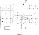
- the converter 10-1 is a resonance converter configured to convert a DC voltage into a DC voltage and comprises three so-called "main" resonant circuits. However, it could include a different number of main resonant circuits.
- each main resonant circuit comprises a transformer, each comprising at least one primary winding P1, P2, P3 and at least one secondary winding S1, S2, S3.
- Each main resonant circuit further comprises a resonance capacity CR1, CR2, CR3 and a first inductive element L1, L2, L3.
- the primary winding P1, P2, P3, the resonance capacity CR1, CR2, CR3 and the first inductive element L1, L2, L3 are for example included in a branch of the main resonant circuit called "resonance branch" and are in particular in series.
- the first inductive element L1, L2, L3 can be connected to a terminal of the resonance capacity CR1, CR2, CR3, the other terminal of the resonance capacity CR1, CR2, CR3 being connected to a terminal of l primary winding P1, P2, P3 of the transformer, optionally via a resistor (not shown).
- Each first inductive element L1, L2, L3 forms with the resonance capacity CR1, CR2, CR3 a main resonance circuit of the LC type.
- the first inductive elements L1, L2, L3, are preferably induction coils. Galvanic isolation is carried out between the primary windings P1, P2, P3 and the secondary windings S1, S2, S3 of the transformers of the three main resonant circuits.
- a first mass M1 constitutes a reference potential of the converter 10-1 on the primary side
- a second mass M2 constitutes a reference potential of the converter 10-1 on the secondary side.
- Each main resonant circuit can be connected to an input structure comprising switches Q1-Q6 configured to control an energy flowing in the main resonant circuits.
- the switches Q1 - Q6 are arranged in a half-bridge comprising a high switch Q1, Q3, Q5 and a low switch Q2, Q4, Q6 connected at a midpoint.
- the high switch Q1, Q3, Q5 is in particular connected to a high potential VHT of an electrical network of the vehicle, in particular of the high voltage network of the vehicle.
- the low switch Q2, Q4, Q6 is notably connected to a low potential of an electrical network of the vehicle, in particular of the high voltage network of the vehicle. This low potential corresponds in particular to the first mass M1.
- the midpoint is connected to the corresponding main resonant circuit, in particular to the resonance branch comprising the primary winding P1, P2, P3 of the transformer of said main resonant circuit.
- the switches Q1-Q6 are for example transistors, in particular of the MOS type.
- Capacities C1-C6 are connected in parallel with switches Q1-Q6 to allow ZVS switching of switches Q1-Q6.
- Each main resonant circuit can be connected to an output structure comprising switches Q7-Q12 configured to control an energy flowing in the main resonant circuits.
- the switches Q7-Q12 are arranged in a half-bridge comprising a high switch Q7, Q9, Q11 and a low switch Q8, Q10, Q12 connected at a midpoint.
- the high switch Q7, Q9, Q11 is in particular connected to a high potential of an electrical network of the vehicle, in particular of the low voltage network of the vehicle.
- the low switch Q8, Q10, Q12 is in particular connected to a low potential of an electrical network of the vehicle, in particular of the low voltage network of the vehicle. This low potential corresponds in particular to the second mass M2.
- the midpoint is connected to the corresponding main resonant circuit, in particular to a branch comprising the secondary winding S1, S2, S3 of the transformer of said main resonant circuit.
- the switches Q7-Q12 are for example transistors, in particular of the MOS type.
- Capacities C7-C12 are connected in parallel with switches Q7-Q12 to allow ZVS switching of switches Q7-Q12.
- the converter 10-1 notably comprises a control unit UC which is configured to control the switches Q1-Q12 of the converter.
- a second inductive element (not shown) can be added in parallel with the secondary winding S1, S2, S3 of the transformer of said main resonant circuit or in parallel with the primary winding P1, P2 , P3 of the transformer of said main resonant circuit.
- This second inductive element is preferably an induction coil.
- This second inductive element makes it possible to produce, with the first inductive element L1, L2, L3 and the resonance capacity CR1, CR2, CR3, a main resonant circuit of the LLC type.
- the second inductive element may be the secondary winding S1, S2, S3 of the transformer of the main resonant circuit when said secondary winding S1, S2, S3 has a magnetizing inductance, or the primary winding P1, P2, P3 of the transformer of the main resonant circuit when said primary winding P1, P2, P3 has a magnetizing inductance.
- a magnetizing inductor can be produced by an air gap in the core of the transformer.
- the main resonant circuits are such that the primary windings P1, P2, P3 are connected to a first point called “neutral” PN1 and the secondary windings S1, S2, S3 are connected to a second point called “neutral” PN2.
- the first neutral point PN1 is connected to the first ground M1 of the DC-DC converter via a first impedance Z1 configured to store energy and allow zero voltage switching of the switches Q1-Q6 of the input structures of the DC converter. continuous at resonance 10-1.
- the first impedance Z1 makes it possible to operate the converter 10-1 into ZVS whatever the operating point of the converter 10-1, when the converter 10-1 transfers energy from the primary to the secondary.
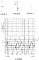
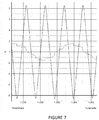
- FIG. 6 which includes a graph representing the voltage VP1 at a midpoint P1 of the input structure of the first main resonant circuit comprising the first inductive element L1 and the resonance capacity CR1.
- the figure 6 also includes a graph representing the current 12 (in dashed lines) flowing in the low transistor Q2 of the input structure of the first main resonant circuit and the current l1 flowing in a first impedance Z1 as illustrated in figure 3 .
- the switches Q1-Q6 of the input structures switch periodically so as to transfer energy from the primary side to the secondary side.
- the first impedance Z1 receives a harmonic current of rank 3.
- the capacitance Cs of the impedance Z1 makes it possible to avoid a direct component in the voltage across the inductance L of the impedance Z1, which would otherwise lead to a growth of the current i2 towards infinity.
- a capacitance C2 in parallel with the given low transistor Q2 by taking a maximum value of the input voltage VHT, and a minimum value for the current I2, one can choose an inductance value L which makes it possible to store the energy necessary for switching at zero voltage across the terminals of the low switch Q2 of the input structure of the first main resonant circuit, and more generally for all the switches of the input structures.
- the first impedance Z1 allows a similar behavior for the other switches Q1-Q6 of the input structures.
- the harmonic current i2 of rank 3 flowing in the first impedance Z1 in particular in the inductance L, makes it possible to discharge the capacitor C2-C6 in parallel with the switches Q1-Q6 of the input structures. This makes it possible to open switches Q1-Q6 at zero voltage.
- an interlaced converter 1 of the prior art comprising circuits LC resonants, such as the one illustrated in figure 1 , does not allow ZVS to be performed over the entire operating range of converter 1.
- the resonance of the inductive element L100, L200, L300 with the resonance capacity C100, C200, C300 may not be sufficient to store energy for this purpose.
- the first impedance Z1 is however always available to store the energy necessary for the ZVS.
- the second neutral point PN2 is connected to the second mass M2 of the DC-DC converter via a second impedance Z2 configured to store energy and allow zero voltage switching of the switches Q7-Q12 of the output structures of the resonant dc-dc converter.
- the second impedance Z1 makes it possible to operate the converter 10-1 to ZVS whatever the operating point of the converter 10-1, when the DC-DC converter with resonance transfers energy from the secondary to the primary. This is particularly suitable when the DC-DC voltage converter with resonance 10-1 is intended to exchange energy not only from primary to secondary, but also from secondary to primary, that is to say when the DC to DC resonant voltage converter is intended to operate bidirectionally.
- the converter 10-1 could be unidirectional, and for example allow only an exchange of energy from the primary to the secondary.
- the converter 10-1 is then devoid of output structures as described above, but may include diodes replacing the switches.
- the converter 10-1 can then be devoid of the second impedance Z2, or even of the second neutral point PN2.
- the output structures can then be similar to those of the converter of the figure 1 .
- the first and second impedances Z1, Z2 can be so-called “subsidiary” resonant circuits, for example as illustrated in figures 3 and 4 .
- the impedance Z1, Z2 can include an inductance L in series with a capacitance Cs, as in figure 3 for example.
- the impedance Z1, Z2 can include an inductance L in parallel with a capacitance C P , which come in series with a capacitance Cs, as in figure 4 for example.
- the behavior of the impedance Z1, Z2 can be modified with the frequency at which the switches of the input or output structures switch.
- the impedance Z1, Z2 can be of any type making it possible to store energy with a view to making zero-voltage switching, for example an inductance L as illustrated in figure 5 .
Landscapes
- Engineering & Computer Science (AREA)
- Power Engineering (AREA)
- Transportation (AREA)
- Mechanical Engineering (AREA)
- Dc-Dc Converters (AREA)
- Electric Propulsion And Braking For Vehicles (AREA)
Abstract
- les circuits résonants principaux sont connectés ensemble en au moins un point neutre (PN1, PN2) différent d'une masse (M1 ,M2) du convertisseur,
- ledit point neutre (PN1, PN2) étant relié à une masse (M1, M2) du convertisseur par une impédance (Z1, Z2) configurée pour stocker de l'énergie et permettre une commutation à tension nulle d'interrupteurs (Q1-Q12) du convertisseur continu-continu à résonance.
Description
- De façon générale, l'invention concerne un convertisseur de tension continu-continu à résonance, notamment dans le domaine des systèmes électriques, plus particulièrement destinés à la recharge d'une batterie d'alimentation, notamment destinés à être embarqués dans un véhicule automobile, tel qu'un véhicule automobile à moteur électrique ou hybride.
- Plus précisément, dans le contexte d'un véhicule électrique ou hybride comprenant une batterie d'alimentation basse tension pour l'alimentation d'équipements électriques du véhicule et une batterie d'alimentation haute tension pour participer à la propulsion du véhicule, il est connu qu'un chargeur embarqué, couramment désigné par l'homme du métier sous l'acronyme OBC pour « On Board Charger » en anglais, comprenant un convertisseur de tension continu-continu à résonance, soit utilisé pour la recharge de la batterie d'alimentation haute tension.
- L'invention concerne ainsi un convertisseur de tension continu-continu à résonance ainsi qu'un chargeur électrique comprenant un tel convertisseur. Le chargeur électrique est en particulier embarqué dans un véhicule électrique ou hybride pour notamment permettre la charge électrique d'une batterie d'alimentation haute tension du véhicule et/ou la fourniture d'énergie électrique par ladite batterie d'alimentation haute tension vers l'extérieur du véhicule, par exemple à un réseau électrique, un équipement ou un immeuble.
- Comme cela est connu, un véhicule automobile électrique ou hybride comprend un système de motorisation électrique, alimenté par une batterie d'alimentation haute tension via un réseau électrique embarqué haute tension, et une pluralité d'équipements électriques auxiliaires alimentés par une batterie d'alimentation basse tension via un réseau électrique embarqué basse tension. Ainsi, la batterie d'alimentation haute tension assure une fonction d'alimentation en énergie du système de motorisation électrique permettant la propulsion du véhicule. La batterie d'alimentation basse tension alimente des équipements électriques auxiliaires, tels que des calculateurs embarqués, des moteurs de lève-vitres, un système multimédia, etc. La batterie d'alimentation haute tension délivre typiquement une tension comprise entre 100 V et 900 V, de préférence entre 100 V et 500 V, tandis que la batterie d'alimentation basse tension délivre typiquement une tension de l'ordre de 12 V, 24 V ou 48 V. Ces deux batteries d'alimentation haute et basse tension doivent pouvoir être chargées.
- La recharge en énergie électrique de la batterie d'alimentation haute tension est réalisée de manière connue en la connectant, via un réseau électrique haute tension continue du véhicule, à un réseau d'alimentation électrique externe, par exemple le réseau électrique alternatif domestique. A cette fin, la batterie d'alimentation haute tension est apte à être connectée au réseau d'alimentation électrique alternatif domestique, pour sa charge, via un chargeur électrique embarqué, désigné OBC.
- Dans une solution connue, un tel chargeur embarqué comprend principalement un circuit correcteur de facteur de puissance, appelé PFC (pour « Power Factor Correction » en anglais), et un convertisseur de tension continu-continu à résonance permettant notamment de réaliser l'isolation galvanique entre le réseau alternatif et le réseau continu. Dans une application de véhicule électrique ou hybride, il peut être nécessaire d'utiliser plusieurs convertisseurs de tension continu-continu afin de parvenir à produire la puissance nécessaire, par exemple en les connectant en parallèle. Cependant, un tel agencement peut nécessiter l'utilisation de filtres qui entrainent une surchauffe des composants. Une méthode connue pour remédier à cet inconvénient consiste à entrelacer les convertisseurs de tension continu-continu, comme cela est représenté à la
figure 1 à titre d'exemple pour trois convertisseurs formant un ensemble 1 de convertisseurs. Un tel entrelacement permet de piloter les convertisseurs à une même fréquence. - Il existe plusieurs topologies de convertisseur de tension continu-continu à résonance. Parmi ces topologies, on distingue notamment les convertisseurs de type LLC. De tels convertisseurs comprennent de manière connue un transformateur, comprenant une partie primaire et une partie secondaire ; une capacité ; deux bobines ; et des interrupteurs qui sont commutés de façon à permettre la conversion d'une première tension continue délivrée à la partie primaire en une deuxième tension continue fournie par la partie secondaire. Afin de réduire les pertes par commutation des interrupteurs, il est connu d'ajouter une capacité en parallèle de chaque interrupteur, une telle configuration permettant un fonctionnement de commutation à tension nulle appelé « ZVS » (Zero-Voltage Switching) par l'homme du métier. Dans un circuit de type LC, dans lequel on note Lr l'élément inductif, par exemple une bobine, et Cr la capacité de résonance, le fonctionnement en ZVS ne peut pas être mis en oeuvre de manière permanente dans des applications hautes tensions. En effet, un tel fonctionnement en ZVS nécessite de stocker de l'énergie dans la bobine Lr. Or, à des valeurs de tensions de 400 V ou supérieures, à laquelle fonctionnent de tels convertisseurs de tension continu-continu à résonance dans les véhicules électriques ou hybrides de nos jours, l'énergie traversant les interrupteurs est telle qu'elle ne peut plus être entièrement stockée dans la bobine Lr, ce qui entraine des pertes par commutation au niveau des interrupteurs. Un circuit de type LLC permet de remédier en partie à ces inconvénients, car l'ajout d'un deuxième élément inductif, noté Lm, permet de stocker de l'énergie supplémentaire par rapport à un circuit de type LC. Cependant, lorsque le deuxième élément inductif est intégré dans la partie primaire du transformateur, le stockage d'énergie nécessite une configuration particulière du transformateur, ce dernier n'étant pas adapté à l'origine pour stocker de l'énergie. Aussi, afin de permettre à la partie primaire du transformateur de stocker de l'énergie, il est connu de réaliser un entrefer dans le noyau du transformateur, notamment dans la partie primaire. Ce faisant, cela rend le transformateur plus complexe et plus onéreux à fabriquer, augmente les perturbations électromagnétiques, et peut produire des effets de bord connus sous le nom de « fringing effects » par l'homme du métier pouvant entrainer des pertes thermiques.
- Il existe donc le besoin d'une solution simple, fiable et efficace de chargeur électrique permettant de remédier au moins en partie à ces inconvénients.
- A cet effet, l'invention a tout d'abord pour objet un convertisseur de tension continu-continu à résonance, notamment pour véhicule électrique ou hybride, ledit convertisseur comprenant n circuits résonants principaux entrelacés, n étant un entier naturel supérieur ou égal à deux, et dans lequel :
- les circuits résonants principaux sont connectés en un même point neutre différent d'une masse du convertisseur,
- ledit point neutre étant relié à la masse du convertisseur par une impédance configurée pour stocker de l'énergie et permettre une commutation à tension nulle d'interrupteurs du convertisseur continu-continu à résonance.
- Grâce à la dite impédance, le convertisseur de tension continu-continu à résonance peut stocker de l'énergie afin de mettre en oeuvre une commutation à tension nulle (ZVS) quel que soit le point de fonctionnement du convertisseur, c'est-à-dire quel que soit son couple tension d'entrée-tension de sortie. Le convertisseur de tension continu-continu à résonance peut ainsi fonctionner en ZVS indépendamment de la charge appliquée en sortie du convertisseur. Cette caractéristique est particulièrement adaptée au cas où les circuits résonants principaux sont de type LC, car elle permet de fonctionner en ZVS quel que soit le point de fonctionnement du convertisseur. L'impédance permet notamment un stockage d'énergie pour les courants dont les harmoniques sont multiples de rang n, où n est le nombre de circuits résonants principaux. Par point neutre, on entend notamment un noeud électrique auquel tous les circuits résonant principaux sont connectés. En particulier, ledit noeud électrique reçoit un courant électrique de chaque circuit résonant principal, ce courant déterminant une sortie du circuit résonant principal.
- Selon une variante, ladite impédance comprend une inductance, notamment une inductance en série avec une capacité.
- Selon une variante, ladite impédance forme un circuit résonant subsidiaire différent desdits circuits résonants principaux. Notamment, le circuit résonant subsidiaire forme un circuit de type LC, ou LLC, ou d'un autre type de circuit résonant. En particulier, ledit circuit résonant subsidiaire comprend une inductance en série avec une capacité, ou une inductance en parallèle avec une capacité. La fréquence de résonance du circuit résonant subsidiaire permet d'améliorer la commutation à zéro de tension à des plages de fonctionnement spécifiques du convertisseur de tension continu-continu.
- Selon une variante, chaque circuit résonant principal comporte un transformateur comprenant au moins un enroulement primaire et au moins un enroulement secondaire, et ledit point neutre est connecté à une borne d'un enroulement du transformateur de chaque circuit résonant principal. En particulier, les transformateurs desdits circuits résonants principaux sont configurés pour transmettre une énergie entre une entrée et une sortie du convertisseur continu-continu à résonance. Notamment, la pluralité d'enroulements primaires est isolée galvaniquement de la pluralité d'enroulements secondaires afin de ne pas réaliser de liaison électrique entre les deux.
- Selon une variante, un premier point neutre est connecté aux enroulements primaires des transformateurs de chaque circuit résonant principal. Autrement dit, les enroulements primaires desdits transformateurs, sont connectés ensemble au niveau d'un même point neutre appelé « premier point neutre » différent d'une masse du convertisseur. Notamment, le premier point neutre est différent d'une masse côté primaire ou d'une masse côté secondaire. Le premier point neutre est relié à la masse du convertisseur, notamment à la masse côté primaire, par une impédance configurée pour stocker de l'énergie et permettre une commutation à tension nulle d'interrupteurs du convertisseur continu-continu à résonance. Grâce à l'impédance connectée au premier point neutre, le convertisseur peut mettre en oeuvre des commutations à tension nulle pour des interrupteurs du convertisseur qui sont situés au côté primaire du convertisseur. En particulier, des branches comprenant chacune un desdits enroulements primaire des transformateurs sont reliées au niveau du premier point neutre.
- Selon une variante, les circuits résonants principaux du convertisseur sont reliés chacun à une structure d'entrée respective comprenant au moins un interrupteur configuré pour contrôler une énergie circulant dans le circuit résonant principal, et l'impédance connectée au premier point neutre est configurée pour stocker de l'énergie et permettre une commutation à tension nulle des interrupteurs desdites structures d'entrée. En particulier, les structures d'entrées sont reliées au côté primaire du transformateur des circuits résonants principaux. Notamment, la structure d'entrée comporte une structure en demi-pont comprenant un interrupteur haut et un interrupteur bas reliés au niveau d'un point milieu, ledit point milieu étant connecté au circuit résonant principal respectif.
- Selon une variante, un deuxième point neutre est connecté aux enroulements secondaires des transformateurs de chaque circuit résonant principal. Autrement dit, les enroulements secondaires desdits transformateurs, sont connectés ensemble au niveau d'un même point neutre appelé « deuxième point neutre » différent d'une masse du convertisseur. Notamment, le deuxième point neutre est différent d'une masse côté primaire ou d'une masse côté secondaire. Le deuxième point neutre est relié à la masse du convertisseur, notamment à la masse côté secondaire, par une impédance configurée pour stocker de l'énergie et permettre une commutation à tension nulle d'interrupteurs du convertisseur continu-continu à résonance. Grâce à l'impédance connectée au deuxième point neutre, le convertisseur peut mettre en oeuvre des commutations à tension nulle pour des interrupteurs du convertisseur qui sont situés au côté secondaire du convertisseur. En particulier, des branches comprenant chacune un desdits enroulements secondaires des transformateurs sont reliées au niveau du deuxième point neutre.
- Selon une variante, les circuits résonants principaux du convertisseur sont reliés chacun à une structure de sortie respective comprenant au moins un interrupteur configuré pour contrôler une énergie circulant dans le circuit résonant principal, et l'impédance connectée au deuxième point neutre est configurée pour stocker de l'énergie et permettre une commutation à tension nulle des interrupteurs desdites structures de sortie. En particulier, les structures de sortie sont reliées au côté secondaire du transformateur, notamment aux enroulements secondaires, des circuits résonants principaux. Notamment, la structure de sortie comporte une structure en demi-pont comprenant un interrupteur haut et un interrupteur bas reliés au niveau d'un point milieu, ledit point milieu étant connecté au circuit résonant principal respectif.
- Notamment le premier point neutre est différent du deuxième point neutre. En particulier, le premier point neutre est connecté uniquement aux enroulements primaires et/ou le second point neutre est connecté uniquement aux enroulements secondaires.
- Selon une variante, chaque circuit résonant principal comprend au moins un premier élément inductif et une capacité de résonance reliée audit premier élément inductif, configurés pour résonner entre eux. Notamment, ledit premier élément inductif, la capacité de résonance et l'enroulement primaire du transformateur sont compris dans une branche du circuit de résonance principal, dite « branche de résonance ». En particulier, le premier point neutre est connecté aux branches de résonance des circuits résonants principaux.
- Selon une variante, chaque circuit résonant principal est au moins de type LC.
- Notamment, le transformateur de chaque circuit résonant principal comprend un deuxième élément inductif. Le deuxième élément inductif est notamment connecté en parallèle de l'enroulement primaire afin de former un circuit résonant principal de type LLC.
- Selon un aspect de l'invention, les premiers éléments inductifs et/ou les deuxièmes éléments inductifs sont des bobines à induction.
- L'invention concerne aussi un chargeur électrique, notamment pour véhicule électrique ou hybride, comprenant un convertisseur tel que présenté précédemment.
- L'invention concerne aussi un véhicule électrique ou hybride comprenant un convertisseur de tension continu-continu tel que présenté précédemment.
- L'invention sera mieux comprise à la lecture de la description qui va suivre, donnée uniquement à titre d'exemple, et se référant aux dessins annexés donnés à titre d'exemples non limitatifs, dans lesquels des références identiques sont données à des objets semblables et sur lesquels :
- la
figure 1 représente un exemple de convertisseur continu-continu à résonance entrelacé de l'art antérieur, - la
figure 2 représente un exemple d'un convertisseur selon l'invention, - les
figures 3 à 5 représentent des exemples d'une impédance connectée au point neutre du convertisseur de lafigure 2 , - les
figures 6 et7 illustrent des courants circulants dans le convertisseur de lafigure 2 . - Il faut noter que les figures exposent l'invention de manière détaillée pour mettre en oeuvre l'invention, lesdites figures pouvant bien entendu servir à mieux définir l'invention le cas échéant.
- Dans la description qui sera faite ci-après, l'invention sera décrite dans son application à un véhicule automobile électrique ou hybride sans que cela ne soit limitatif de la portée de la présente invention.
- Par exemple, un tel véhicule peut comprendre notamment une machine électrique, un onduleur, un ensemble de convertisseurs, une batterie d'alimentation haute tension, un réseau électrique embarqué haute tension, une batterie d'alimentation basse tension, un réseau électrique embarqué basse tension et une pluralité d'équipements électriques auxiliaires.
- Le convertisseur selon l'invention est décrit ci-après dans sa mise en oeuvre pour un convertisseur DCDC embarqué dans le véhicule afin de convertir une tension entre les réseaux électriques basse et haute tension, sans toutefois que cela ne limite la portée de la présente invention. On notera ainsi que le convertisseur pourrait être compris dans un chargeur électrique, notamment embarqué dans un véhicule.
- Le réseau électrique embarqué basse tension relie la batterie d'alimentation basse tension et la pluralité d'équipements électriques auxiliaires afin que la batterie d'alimentation basse tension alimente lesdits équipements électriques auxiliaires, tels que des calculateurs embarqués, des moteurs de lève-vitres, un système multimédia, etc. La batterie d'alimentation basse tension délivre typiquement par exemple une tension de l'ordre de 12 V, 24 V ou 48 V. La recharge de la batterie basse tension est réalisée à partir de la batterie haute tension via un convertisseur de tension continue en tension continue, appelé communément convertisseur continu-continu (DCDC).
- Le réseau électrique embarqué haute tension relie la batterie d'alimentation haute tension et l'onduleur afin que la batterie d'alimentation haute tension assure une fonction d'alimentation en énergie de la machine électrique via l'onduleur. La batterie d'alimentation haute tension délivre typiquement une tension comprise entre 100 V et 900 V, de préférence entre 100 V et 500 V. La recharge en énergie électrique de la batterie d'alimentation haute tension est réalisée en la connectant, via le réseau électrique haute tension continue du véhicule, à un réseau électrique externe, par exemple le réseau électrique alternatif domestique.
- La machine électrique est une machine électrique tournante, de préférence destinée à entrainer les roues du véhicule à partir de l'énergie fournie par la batterie d'alimentation haute-tension. Plus précisément, la machine électrique est une machine électrique à courant alternatif alimentée par une source de courants polyphasés. Par exemple, la machine électrique peut être un moteur à courant alternatif. Dans l'exemple préféré décrit ci-après, la machine électrique est alimentée par une source de courants triphasés sans que cela ne soit limitatif de la portée de la présente invention.
- Dans cet exemple, la commande de la machine électrique est réalisée au moyen de l'onduleur. Ledit onduleur permet de convertir le courant continu fourni par la batterie d'alimentation haute tension en trois courants de commande alternatifs, par exemple sinusoïdaux. Autrement dit, l'onduleur a pour fonction de transformer le courant continu délivré par la batterie d'alimentation haute tension en trois courants de phase permettant de commander la machine électrique. A l'inverse, dans un autre mode de fonctionnement, la machine électrique peut également fournir trois courants alternatifs à l'onduleur afin que ledit onduleur les transforme en un courant continu permettant de charger la batterie d'alimentation haute-tension.
- On a représenté en
figure 2 un exemple d'un convertisseur électrique 10-1 selon l'invention. - Le convertisseur 10-1 est un convertisseur à résonance configuré pour convertir une tension continue en une tension continue et comprend trois circuits résonants dits « principaux ». Cependant, il pourrait comprendre un nombre différent de circuits résonants principaux.
- Notamment, chaque circuit résonant principal comporte un transformateur, comprenant chacun au moins un enroulement primaire P1, P2, P3 et au moins un enroulement secondaire S1, S2, S3. Chaque circuit résonant principal comprend en outre une capacité de résonance CR1, CR2, CR3 et un premier élément inductif L1, L2, L3. L'enroulement primaire P1, P2, P3, la capacité de résonance CR1, CR2, CR3 et le premier élément inductif L1, L2, L3 sont par exemple compris dans une branche du circuit résonant principal dite « branche de résonance » et sont notamment en série. Par exemple, le premier élément inductif L1, L2, L3 peut être relié à une borne de la capacité de résonance CR1, CR2, CR3, l'autre borne de la capacité de résonance CR1, CR2, CR3 étant reliée à une borne de l'enroulement primaire P1, P2, P3 du transformateur, optionnellement via une résistance (non représentée). Chaque premier élément inductif L1, L2, L3 forme avec la capacité de résonance CR1, CR2, CR3 un circuit de résonance principal de type LC.
- Les premiers éléments inductifs L1, L2, L3, sont de préférence des bobines à induction. Une isolation galvanique est réalisée entre les enroulements primaires P1, P2, P3 et les enroulements secondaires S1, S2, S3 des transformateurs des trois circuits résonants principaux. Une première masse M1 constitue un potentiel de référence du convertisseur 10-1 côté primaire, et une deuxième masse M2 constitue un potentiel de référence du convertisseur 10-1 côté secondaire.
- Chaque circuit résonant principal peut être connecté à une structure d'entrée comportant des interrupteurs Q1-Q6 configurés pour contrôler une énergie circulant dans les circuits résonants principaux. En particulier, dans chaque structure d'entrée, les interrupteurs Q1 - Q6 sont agencés en demi-pont comprenant un interrupteur haut Q1, Q3, Q5 et un interrupteur bas Q2, Q4, Q6 reliés au niveau d'un point milieu. L'interrupteur haut Q1, Q3, Q5 est notamment connecté à un potentiel haut VHT d'un réseau électrique du véhicule, notamment du réseau haute tension du véhicule. L'interrupteur bas Q2, Q4, Q6 est notamment connecté à un potentiel bas d'un réseau électrique du véhicule, notamment du réseau haute tension du véhicule. Ce potentiel bas correspond notamment à la première masse M1. Le point milieu est relié au circuit résonnant principal correspondant, notamment à la branche de résonance comprenant l'enroulement primaire P1, P2, P3 du transformateur dudit circuit résonant principal. Les interrupteurs Q1-Q6 sont par exemple des transistors, notamment de type MOS. Des capacités C1-C6 sont connectées en parallèle des interrupteurs Q1-Q6 pour permettre des commutations ZVS des interrupteurs Q1-Q6.
- Chaque circuit résonant principal peut être connecté à une structure de sortie comportant des interrupteurs Q7-Q12 configurés pour contrôler une énergie circulant dans les circuits résonants principaux. En particulier, dans chaque structure de sortie, les interrupteurs Q7-Q12 sont agencés en demi-pont comprenant un interrupteur haut Q7, Q9, Q11 et un interrupteur bas Q8, Q10, Q12 reliés au niveau d'un point milieu. L'interrupteur haut Q7, Q9, Q11 est notamment connecté à un potentiel haut d'un réseau électrique du véhicule, notamment du réseau basse tension du véhicule. L'interrupteur bas Q8, Q10, Q12 est notamment connecté à un potentiel bas d'un réseau électrique du véhicule, notamment du réseau basse tension du véhicule. Ce potentiel bas correspond notamment à la deuxième masse M2. Le point milieu est relié au circuit résonnant principal correspondant, notamment à une branche comprenant l'enroulement secondaire S1, S2, S3 du transformateur dudit circuit résonant principal. Les interrupteurs Q7-Q12 sont par exemple des transistors, notamment de type MOS. Des capacités C7-C12 sont connectées en parallèle des interrupteurs Q7-Q12 pour permettre des commutations ZVS des interrupteurs Q7-Q12.
- Le convertisseur 10-1 comprend notamment une unité de commande UC qui est configurée pour commander les interrupteurs Q1-Q12 du convertisseur.
- De manière avantageuse, dans chaque circuit résonant principal, un deuxième élément inductif (non représenté) peut être ajouté en parallèle de l'enroulement secondaire S1, S2, S3 du transformateur dudit circuit résonant principal ou en parallèle de l'enroulement primaire P1, P2, P3 du transformateur dudit circuit résonant principal. Ce deuxième élément inductif est de préférence une bobine à induction. Ce deuxième élément inductif permet de réaliser, avec le premier élément inductif L1, L2, L3 et la capacité de résonance CR1, CR2, CR3, un circuit résonant principal de type LLC. On notera que, de manière alternative, le deuxième élément inductif peut être l'enroulement secondaire S1, S2, S3 du transformateur du circuit résonant principal lorsque ledit enroulement secondaire S1, S2, S3 présente une inductance magnétisante, ou l'enroulement primaire P1, P2, P3 du transformateur du circuit résonant principal lorsque ledit enroulement primaire P1, P2, P3 présente une inductance magnétisante. Une telle inductance magnétisante peut être réalisée par un entrefer dans le noyau du transformateur.
- Les circuits résonants principaux sont tels que les enroulements primaires P1, P2, P3 sont reliés à un premier point dit « neutre » PN1 et les enroulements secondaires S1, S2, S3 sont reliés à un deuxième point dit « neutre » PN2.
- Le premier point neutre PN1 est relié à la première masse M1 du convertisseur continu-continu via une première impédance Z1 configurée pour stocker de l'énergie et permettre une commutation à tension nulle des interrupteurs Q1-Q6 des structures d'entrée du convertisseur continu-continu à résonance 10-1. La première impédance Z1 permet de faire fonctionner le convertisseur 10-1 en ZVS quel que soit le point de fonctionnement du convertisseur 10-1, lorsque le convertisseur 10-1 transfère de l'énergie du primaire vers le secondaire.
- Ceci sera mieux compris en faisant référence à la
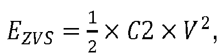
figure 6 qui comprend un graphe représentant la tension VP1 en un point milieu P1 de la structure d'entrée du premier circuit résonant principal comprenant le premier élément inductif L1 et la capacité de résonance CR1. Lafigure 6 comprend également un graphe représentant le courant 12 (en traits interrompus) circulant dans le transistor bas Q2 du la structure d'entrée du premier circuit résonant principal et le courant l1 circulant dans une première impédance Z1 telle qu'illustrée enfigure 3 . - Pendant un fonctionnement du convertisseur 10-1, les interrupteurs Q1-Q6 des structures d'entrées commutent périodiquement de manière à transférer de l'énergie du côté primaire vers le côté secondaire. La première impédance Z1 reçoit un courant d'harmonique de rang 3. L'énergie Ezvs nécessaire à la décharge de la capacité C2 en parallèle de l'interrupteur bas Q2 est donnée par l'expression

- Ceci est particulièrement avantageux lorsque les circuits résonants principaux sont de type LC. En effet, un convertisseur entrelacé 1 de l'art antérieur comprenant des circuits résonants LC, tel que celui illustré en
figure 1 , ne permet pas de faire du ZVS sur toute la plage de fonctionnement du convertisseur 1. Suivant le point de fonctionnement, la résonance de l'élément inductif L100, L200, L300 avec la capacité de résonance C100, C200, C300 peut ne pas être suffisante pour stocker de l'énergie à cet effet. Dans le convertisseur 10-1 selon un exemple de l'invention, la première impédance Z1 est par contre toujours disponible pour stocker l'énergie nécessaire au ZVS. - Dans la
figure 2 , de manière similaire le deuxième point neutre PN2 est relié à la deuxième masse M2 du convertisseur continu-continu via une deuxième impédance Z2 configurée pour stocker de l'énergie et permettre une commutation à tension nulle des interrupteurs Q7-Q12 des structures de sortie du convertisseur continu-continu à résonance. La deuxième impédance Z1 permet de faire fonctionner le convertisseur 10-1 en ZVS quel que soit le point de fonctionnement du convertisseur 10-1, lorsque le convertisseur continu-continu à résonance transfère de l'énergie du secondaire vers le primaire. Ceci est particulièrement adapté lorsque le convertisseur de tension continu-continu à résonance 10-1 est destiné à échanger de l'énergie non seulement du primaire vers le secondaire, mais aussi du secondaire vers le primaire, c'est-à-dire lorsque le convertisseur de tension continu-continu à résonance est destiné à fonctionner de façon bidirectionnelle. - Cependant, le convertisseur 10-1 pourrait être unidirectionnel, et par exemple permettre seulement un échange d'énergie du primaire vers le secondaire. Le convertisseur 10-1 est alors dépourvu de structures de sortie telles que décrites précédemment, mais peut comprendre des diodes remplaçant les interrupteurs. Le convertisseur 10-1 peut être alors dépourvu de la deuxième impédance Z2, voire même du deuxième point neutre PN2. Les structures de sortie peuvent alors être similaires à celles du convertisseur de la
figure 1 . - Les première et deuxième impédances Z1, Z2 peuvent être des circuits résonants dits « subsidiaires », par exemple tels qu'illustrés en
figures 3 et 4 . En particulier, l'impédance Z1, Z2 peut comprendre une inductance L en série avec une capacité Cs, comme enfigure 3 par exemple. L'impédance Z1, Z2 peut comprendre une inductance L en parallèle avec une capacité CP, qui viennent en série avec une capacité Cs, comme enfigure 4 par exemple. Avantageusement, lorsque l'impédance Z1, Z2 est un circuit résonant subsidiaire, on peut modifier le comportement de l'impédance Z1, Z2 avec la fréquence à laquelle commutent les interrupteurs des structures d'entrée ou de sortie. Ce qui permet par exemple d'obtenir plus ou moins des courants de plus ou moins grandes intensités dans le convertisseur en fonction des points de fonctionnement. Cependant, l'impédance Z1, Z2 peut être de tout type permettant de stocker de l'énergie en vue de faire de la commutation à tenson nulle, par exemple une inductance L comme illustré enfigure 5 .
Claims (9)
- Convertisseur (10-1) de tension continu-continu à résonance, notamment pour véhicule électrique ou hybride, ledit convertisseur (10-1) comprenant n circuits résonants principaux entrelacés, n étant un entier naturel supérieur ou égal à deux, et dans lequel :- les circuits résonants principaux sont connectés ensemble en au moins un point neutre (PN1, PN2) différent d'une masse (M1, M2) du convertisseur,- ledit point neutre (PN1, PN2) étant relié à une masse (M1, M2) du convertisseur par une impédance configurée pour stocker de l'énergie et permettre une commutation à tension nulle d'interrupteurs du convertisseur continu-continu à résonance.
- Convertisseur selon la revendication 1, dans lequel ladite impédance comprend une inductance.
- Convertisseur (10-1) selon l'une quelconque des revendications 1 ou 2, dans lequel ladite impédance forme un circuit résonant subsidiaire différent desdits circuits résonants principaux.
- Convertisseur (10-1) selon l'une quelconque des revendications précédentes, dans lequel chaque circuit résonant principal comporte un transformateur comprenant au moins un enroulement primaire (P1, P2, P3) et au moins un enroulement secondaire (S1, S2, S3), et dans lequel ledit point neutre (PN1, PN2) est connecté à une borne d'un enroulement du transformateur de chaque circuit résonant principal.
- Convertisseur (10-1) selon la revendication précédente, dans lequel un premier point neutre (PN1) est connecté aux enroulements primaires des transformateurs de chaque circuit résonant principal.
- Convertisseur (10-1) selon la revendication précédente, dans lequel les circuits résonants principaux du convertisseur (10-1) sont reliés chacun à une structure d'entrée respective comprenant au moins un interrupteur configuré pour contrôler une énergie circulant dans le circuit résonant principal, l'impédance connectée au premier point neutre (PN1) étant configurée pour stocker de l'énergie et permettre une commutation à tension nulle des interrupteurs desdites structures d'entrée.
- Convertisseur (10-1) selon l'une quelconque des revendications 4 à 6, dans lequel un deuxième point neutre (PN2) est connecté aux enroulements secondaires des transformateurs de chaque circuit résonant principal.
- Convertisseur (10-1) selon la revendication précédente, dans lequel les circuits résonants principaux du convertisseur (10-1) sont reliés chacun à une structure de sortie respective comprenant au moins un interrupteur configuré pour contrôler une énergie circulant dans ledit circuit résonant principal, l'impédance connectée au deuxième point neutre (PN2) étant configurée pour stocker de l'énergie et permettre une commutation à tension nulle des interrupteurs desdites structures de sortie.
- Convertisseur (10-1) de tension continu-continu à résonance, selon l'une des revendications précédentes, dans lequel chaque circuit résonant principal comprend au moins un premier élément inductif (L1, L2, L3), une capacité de résonance (CR1, CR2, CR3) reliée audit premier élément inductif (L1, L2, L3), configurés pour résonner entre eux.
Applications Claiming Priority (1)
| Application Number | Priority Date | Filing Date | Title |
|---|---|---|---|
| FR1857150A FR3084796B1 (fr) | 2018-07-31 | 2018-07-31 | Convertisseur de tension continu-continu a resonance |
Publications (2)
| Publication Number | Publication Date |
|---|---|
| EP3605820A1 true EP3605820A1 (fr) | 2020-02-05 |
| EP3605820B1 EP3605820B1 (fr) | 2023-05-10 |
Family
ID=63896369
Family Applications (1)
| Application Number | Title | Priority Date | Filing Date |
|---|---|---|---|
| EP19186951.0A Active EP3605820B1 (fr) | 2018-07-31 | 2019-07-18 | Convertisseur de tension continu-continu a resonance |
Country Status (5)
| Country | Link |
|---|---|
| US (1) | US11336186B2 (fr) |
| EP (1) | EP3605820B1 (fr) |
| KR (1) | KR20200014214A (fr) |
| CN (1) | CN110784110A (fr) |
| FR (1) | FR3084796B1 (fr) |
Families Citing this family (6)
| Publication number | Priority date | Publication date | Assignee | Title |
|---|---|---|---|---|
| WO2021111601A1 (fr) * | 2019-12-05 | 2021-06-10 | 三菱電機株式会社 | Tranformateur d'isolation et dispositif de conversion de puissance équipé de celui-ci |
| US11404966B2 (en) | 2020-07-02 | 2022-08-02 | Delta Electronics, Inc. | Isolated multi-phase DC/DC converter with reduced quantity of blocking capacitors |
| CN114056131B (zh) * | 2020-08-05 | 2023-05-05 | 比亚迪股份有限公司 | 充放电控制方法、车载充电系统和车辆 |
| CN115589149A (zh) * | 2021-07-06 | 2023-01-10 | 光宝电子(广州)有限公司 | 三相交错谐振变换器和电源电路 |
| JP2023168827A (ja) * | 2022-05-16 | 2023-11-29 | 株式会社Gsユアサ | 多相llc共振コンバータ回路 |
| CN118487493A (zh) * | 2023-02-10 | 2024-08-13 | 台达电子工业股份有限公司 | 谐振转换器及谐振转换电路系统 |
Citations (3)
| Publication number | Priority date | Publication date | Assignee | Title |
|---|---|---|---|---|
| US20120163035A1 (en) * | 2010-12-24 | 2012-06-28 | Korea Institute Of Energy Research | Multi-phase interleaved bidirectional dc-dc converter |
| KR101377124B1 (ko) * | 2012-12-28 | 2014-04-01 | 서울과학기술대학교 산학협력단 | 단일 스위치 절연형 공진 컨버터 및 이를 이용한 인터리빙 단일 스위치 절연형 공진 컨버터 |
| US20140368175A1 (en) * | 2013-06-14 | 2014-12-18 | Korea Electrotechnology Research Institute | High precision dc to dc converter with wide load range and gate drive circuit for use therein |
Family Cites Families (14)
| Publication number | Priority date | Publication date | Assignee | Title |
|---|---|---|---|---|
| JP3644615B2 (ja) * | 1997-02-17 | 2005-05-11 | Tdk株式会社 | スイッチング電源 |
| CN2369269Y (zh) * | 1998-12-30 | 2000-03-15 | 中国科学院近代物理研究所 | 大功率高稳定度直流稳流软开关电源 |
| FR2884075A1 (fr) * | 2005-04-04 | 2006-10-06 | Thomson Licensing Sa | Convertisseur de tension continue a commutation douce |
| CN101071994A (zh) * | 2006-05-10 | 2007-11-14 | 周春香 | 一体化三相ac/dc隔离式双向变换器 |
| CN101047337A (zh) * | 2007-04-12 | 2007-10-03 | 艾默生网络能源有限公司 | 一种三电平llc谐振变换器 |
| CN101267160B (zh) * | 2008-04-25 | 2011-07-27 | 艾默生网络能源有限公司 | 一种软开关电路 |
| CN201438412U (zh) * | 2009-03-13 | 2010-04-14 | 上海大一互电力电器有限公司 | 中性点用零序电压互感器 |
| EP2299580A3 (fr) * | 2009-06-24 | 2011-07-27 | STMicroelectronics S.r.l. | Convertisseur résonant multiphases et son procédé de contrôle |
| US8670250B2 (en) * | 2010-09-13 | 2014-03-11 | Futurewei Technologies, Inc. | Common mode noise reduction apparatus and method |
| US8842450B2 (en) * | 2011-04-12 | 2014-09-23 | Flextronics, Ap, Llc | Power converter using multiple phase-shifting quasi-resonant converters |
| TWI439034B (zh) * | 2012-04-23 | 2014-05-21 | Univ Kun Shan | Zero voltage switching power converter |
| US10491123B2 (en) * | 2015-09-18 | 2019-11-26 | Murata Manufacturing Co., Ltd. | Modular parallel technique for resonant converter |
| CN206226010U (zh) * | 2016-12-13 | 2017-06-06 | 国家电网公司 | 变压器中性点接地保护系统 |
| CN106936320B (zh) * | 2017-05-11 | 2024-04-26 | 辽宁工程技术大学 | 一种交错并联磁集成双向全桥llc谐振变换器 |
-
2018
- 2018-07-31 FR FR1857150A patent/FR3084796B1/fr active Active
-
2019
- 2019-07-18 EP EP19186951.0A patent/EP3605820B1/fr active Active
- 2019-07-25 KR KR1020190090104A patent/KR20200014214A/ko active Pending
- 2019-07-29 CN CN201910686936.7A patent/CN110784110A/zh active Pending
- 2019-07-30 US US16/526,138 patent/US11336186B2/en active Active
Patent Citations (3)
| Publication number | Priority date | Publication date | Assignee | Title |
|---|---|---|---|---|
| US20120163035A1 (en) * | 2010-12-24 | 2012-06-28 | Korea Institute Of Energy Research | Multi-phase interleaved bidirectional dc-dc converter |
| KR101377124B1 (ko) * | 2012-12-28 | 2014-04-01 | 서울과학기술대학교 산학협력단 | 단일 스위치 절연형 공진 컨버터 및 이를 이용한 인터리빙 단일 스위치 절연형 공진 컨버터 |
| US20140368175A1 (en) * | 2013-06-14 | 2014-12-18 | Korea Electrotechnology Research Institute | High precision dc to dc converter with wide load range and gate drive circuit for use therein |
Also Published As
| Publication number | Publication date |
|---|---|
| EP3605820B1 (fr) | 2023-05-10 |
| CN110784110A (zh) | 2020-02-11 |
| US20200044571A1 (en) | 2020-02-06 |
| US11336186B2 (en) | 2022-05-17 |
| KR20200014214A (ko) | 2020-02-10 |
| FR3084796B1 (fr) | 2020-08-28 |
| FR3084796A1 (fr) | 2020-02-07 |
Similar Documents
| Publication | Publication Date | Title |
|---|---|---|
| EP3605820B1 (fr) | Convertisseur de tension continu-continu a resonance | |
| EP3605818B1 (fr) | Convertisseur de tension continu-continu a resonance | |
| EP3403872B1 (fr) | Système de chargeur électrique pour véhicule électrique ou hybride | |
| FR3064832A1 (fr) | Systeme de chargeur electrique triphase et monophase pour vehicule electrique ou hybride | |
| WO2007080196A1 (fr) | Autotransformateur a dephasage de 20° | |
| WO2020183076A1 (fr) | Convertisseur de puissance isole et reconfigurable | |
| EP3007349B1 (fr) | Circuit électrique transformateur et installation comportant un tel circuit | |
| FR3104846A1 (fr) | Système électrique pour la conversion de tension continue et la charge de batteries d’alimentation | |
| FR3140983A1 (fr) | Transformateur d'un système électrique pour la conversion de la tension continue et pour la charge des batteries d'un véhicule. | |
| EP3721543A1 (fr) | Convertisseur continu-continu avec pre-charge d'un premier reseau electrique a partir d'un deuxieme reseau electrique | |
| FR3141010A1 (fr) | Système électrique pour la conversion de la tension continue et pour la charge des batteries d'un véhicule. | |
| EP3685485B1 (fr) | Procédé de commande d'un système de charge d'une batterie de traction | |
| EP4077035A1 (fr) | Système de filtre hybride monophasé et triphasé, pour un chargeur électrique | |
| EP3276810B1 (fr) | Convertisseur dc-dc isolé et batterie électrique comprenant un convertisseur dc-dc isolé | |
| EP4382343A1 (fr) | Système d'alimentation électrique alimentant une charge électrique via une tension polyphasée et en outre un réseau auxiliaire via une composante homopolaire de ladite tension, installation électrique associée | |
| FR3082683A1 (fr) | Convertisseur bidirectionnel pour vehicule electrique ou hybride | |
| EP2249477A1 (fr) | Système d' alimentation d'un moteur électrique comprenant un filtre passive à bobines couplées | |
| EP3276812B1 (fr) | Convertisseur dc-dc isolé et batterie électrique comprenant un convertisseur dc-dc isolé | |
| FR3089076A1 (fr) | Convertisseur courant continu - courant continu résonant de type LLC | |
| FR3066866B1 (fr) | Convertisseur continu-continu pour vehicule electrique ou hybride | |
| WO2023232671A1 (fr) | Systeme electrique comprenant trois convertisseurs electriques | |
| WO2024094727A1 (fr) | Système électrique et procédé de charge d'une batterie, notamment pour véhicule | |
| WO2023094701A1 (fr) | Convertisseur de puissance présentant un module de découplage | |
| FR3149721A1 (fr) | Dispositif d’induction électromagnétique | |
| FR2974688A1 (fr) | Convertisseur d'energie electrique |
Legal Events
| Date | Code | Title | Description |
|---|---|---|---|
| PUAI | Public reference made under article 153(3) epc to a published international application that has entered the european phase |
Free format text: ORIGINAL CODE: 0009012 |
|
| STAA | Information on the status of an ep patent application or granted ep patent |
Free format text: STATUS: THE APPLICATION HAS BEEN PUBLISHED |
|
| AK | Designated contracting states |
Kind code of ref document: A1 Designated state(s): AL AT BE BG CH CY CZ DE DK EE ES FI FR GB GR HR HU IE IS IT LI LT LU LV MC MK MT NL NO PL PT RO RS SE SI SK SM TR |
|
| AX | Request for extension of the european patent |
Extension state: BA ME |
|
| STAA | Information on the status of an ep patent application or granted ep patent |
Free format text: STATUS: REQUEST FOR EXAMINATION WAS MADE |
|
| 17P | Request for examination filed |
Effective date: 20200805 |
|
| RBV | Designated contracting states (corrected) |
Designated state(s): AL AT BE BG CH CY CZ DE DK EE ES FI FR GB GR HR HU IE IS IT LI LT LU LV MC MK MT NL NO PL PT RO RS SE SI SK SM TR |
|
| STAA | Information on the status of an ep patent application or granted ep patent |
Free format text: STATUS: EXAMINATION IS IN PROGRESS |
|
| 17Q | First examination report despatched |
Effective date: 20201002 |
|
| REG | Reference to a national code |
Ref country code: DE Ref legal event code: R079 Free format text: PREVIOUS MAIN CLASS: H02M0003337000 Ipc: H02M0003000000 Ref country code: DE Ref legal event code: R079 Ref document number: 602019028617 Country of ref document: DE Free format text: PREVIOUS MAIN CLASS: H02M0003337000 Ipc: H02M0003000000 |
|
| GRAP | Despatch of communication of intention to grant a patent |
Free format text: ORIGINAL CODE: EPIDOSNIGR1 |
|
| STAA | Information on the status of an ep patent application or granted ep patent |
Free format text: STATUS: GRANT OF PATENT IS INTENDED |
|
| RIC1 | Information provided on ipc code assigned before grant |
Ipc: H02M 3/28 20060101ALI20220927BHEP Ipc: H02M 3/335 20060101ALI20220927BHEP Ipc: H02M 3/00 20060101AFI20220927BHEP |
|
| RAP1 | Party data changed (applicant data changed or rights of an application transferred) |
Owner name: VALEO SIEMENS EAUTOMOTIVE FRANCE SAS |
|
| INTG | Intention to grant announced |
Effective date: 20221024 |
|
| GRAS | Grant fee paid |
Free format text: ORIGINAL CODE: EPIDOSNIGR3 |
|
| GRAA | (expected) grant |
Free format text: ORIGINAL CODE: 0009210 |
|
| STAA | Information on the status of an ep patent application or granted ep patent |
Free format text: STATUS: THE PATENT HAS BEEN GRANTED |
|
| AK | Designated contracting states |
Kind code of ref document: B1 Designated state(s): AL AT BE BG CH CY CZ DE DK EE ES FI FR GB GR HR HU IE IS IT LI LT LU LV MC MK MT NL NO PL PT RO RS SE SI SK SM TR |
|
| REG | Reference to a national code |
Ref country code: GB Ref legal event code: FG4D Free format text: NOT ENGLISH |
|
| REG | Reference to a national code |
Ref country code: AT Ref legal event code: REF Ref document number: 1567709 Country of ref document: AT Kind code of ref document: T Effective date: 20230515 Ref country code: CH Ref legal event code: EP |
|
| REG | Reference to a national code |
Ref country code: DE Ref legal event code: R096 Ref document number: 602019028617 Country of ref document: DE |
|
| REG | Reference to a national code |
Ref country code: IE Ref legal event code: FG4D Free format text: LANGUAGE OF EP DOCUMENT: FRENCH |
|
| P01 | Opt-out of the competence of the unified patent court (upc) registered |
Effective date: 20230629 |
|
| REG | Reference to a national code |
Ref country code: LT Ref legal event code: MG9D |
|
| REG | Reference to a national code |
Ref country code: NL Ref legal event code: MP Effective date: 20230510 |
|
| REG | Reference to a national code |
Ref country code: AT Ref legal event code: MK05 Ref document number: 1567709 Country of ref document: AT Kind code of ref document: T Effective date: 20230510 |
|
| PG25 | Lapsed in a contracting state [announced via postgrant information from national office to epo] |
Ref country code: SE Free format text: LAPSE BECAUSE OF FAILURE TO SUBMIT A TRANSLATION OF THE DESCRIPTION OR TO PAY THE FEE WITHIN THE PRESCRIBED TIME-LIMIT Effective date: 20230510 Ref country code: PT Free format text: LAPSE BECAUSE OF FAILURE TO SUBMIT A TRANSLATION OF THE DESCRIPTION OR TO PAY THE FEE WITHIN THE PRESCRIBED TIME-LIMIT Effective date: 20230911 Ref country code: NO Free format text: LAPSE BECAUSE OF FAILURE TO SUBMIT A TRANSLATION OF THE DESCRIPTION OR TO PAY THE FEE WITHIN THE PRESCRIBED TIME-LIMIT Effective date: 20230810 Ref country code: NL Free format text: LAPSE BECAUSE OF FAILURE TO SUBMIT A TRANSLATION OF THE DESCRIPTION OR TO PAY THE FEE WITHIN THE PRESCRIBED TIME-LIMIT Effective date: 20230510 Ref country code: ES Free format text: LAPSE BECAUSE OF FAILURE TO SUBMIT A TRANSLATION OF THE DESCRIPTION OR TO PAY THE FEE WITHIN THE PRESCRIBED TIME-LIMIT Effective date: 20230510 Ref country code: AT Free format text: LAPSE BECAUSE OF FAILURE TO SUBMIT A TRANSLATION OF THE DESCRIPTION OR TO PAY THE FEE WITHIN THE PRESCRIBED TIME-LIMIT Effective date: 20230510 |
|
| PG25 | Lapsed in a contracting state [announced via postgrant information from national office to epo] |
Ref country code: RS Free format text: LAPSE BECAUSE OF FAILURE TO SUBMIT A TRANSLATION OF THE DESCRIPTION OR TO PAY THE FEE WITHIN THE PRESCRIBED TIME-LIMIT Effective date: 20230510 Ref country code: PL Free format text: LAPSE BECAUSE OF FAILURE TO SUBMIT A TRANSLATION OF THE DESCRIPTION OR TO PAY THE FEE WITHIN THE PRESCRIBED TIME-LIMIT Effective date: 20230510 Ref country code: LV Free format text: LAPSE BECAUSE OF FAILURE TO SUBMIT A TRANSLATION OF THE DESCRIPTION OR TO PAY THE FEE WITHIN THE PRESCRIBED TIME-LIMIT Effective date: 20230510 Ref country code: LT Free format text: LAPSE BECAUSE OF FAILURE TO SUBMIT A TRANSLATION OF THE DESCRIPTION OR TO PAY THE FEE WITHIN THE PRESCRIBED TIME-LIMIT Effective date: 20230510 Ref country code: IS Free format text: LAPSE BECAUSE OF FAILURE TO SUBMIT A TRANSLATION OF THE DESCRIPTION OR TO PAY THE FEE WITHIN THE PRESCRIBED TIME-LIMIT Effective date: 20230910 Ref country code: HR Free format text: LAPSE BECAUSE OF FAILURE TO SUBMIT A TRANSLATION OF THE DESCRIPTION OR TO PAY THE FEE WITHIN THE PRESCRIBED TIME-LIMIT Effective date: 20230510 Ref country code: GR Free format text: LAPSE BECAUSE OF FAILURE TO SUBMIT A TRANSLATION OF THE DESCRIPTION OR TO PAY THE FEE WITHIN THE PRESCRIBED TIME-LIMIT Effective date: 20230811 |
|
| PG25 | Lapsed in a contracting state [announced via postgrant information from national office to epo] |
Ref country code: FI Free format text: LAPSE BECAUSE OF FAILURE TO SUBMIT A TRANSLATION OF THE DESCRIPTION OR TO PAY THE FEE WITHIN THE PRESCRIBED TIME-LIMIT Effective date: 20230510 |
|
| PG25 | Lapsed in a contracting state [announced via postgrant information from national office to epo] |
Ref country code: SK Free format text: LAPSE BECAUSE OF FAILURE TO SUBMIT A TRANSLATION OF THE DESCRIPTION OR TO PAY THE FEE WITHIN THE PRESCRIBED TIME-LIMIT Effective date: 20230510 |
|
| PG25 | Lapsed in a contracting state [announced via postgrant information from national office to epo] |
Ref country code: SM Free format text: LAPSE BECAUSE OF FAILURE TO SUBMIT A TRANSLATION OF THE DESCRIPTION OR TO PAY THE FEE WITHIN THE PRESCRIBED TIME-LIMIT Effective date: 20230510 Ref country code: SK Free format text: LAPSE BECAUSE OF FAILURE TO SUBMIT A TRANSLATION OF THE DESCRIPTION OR TO PAY THE FEE WITHIN THE PRESCRIBED TIME-LIMIT Effective date: 20230510 Ref country code: RO Free format text: LAPSE BECAUSE OF FAILURE TO SUBMIT A TRANSLATION OF THE DESCRIPTION OR TO PAY THE FEE WITHIN THE PRESCRIBED TIME-LIMIT Effective date: 20230510 Ref country code: EE Free format text: LAPSE BECAUSE OF FAILURE TO SUBMIT A TRANSLATION OF THE DESCRIPTION OR TO PAY THE FEE WITHIN THE PRESCRIBED TIME-LIMIT Effective date: 20230510 Ref country code: DK Free format text: LAPSE BECAUSE OF FAILURE TO SUBMIT A TRANSLATION OF THE DESCRIPTION OR TO PAY THE FEE WITHIN THE PRESCRIBED TIME-LIMIT Effective date: 20230510 Ref country code: CZ Free format text: LAPSE BECAUSE OF FAILURE TO SUBMIT A TRANSLATION OF THE DESCRIPTION OR TO PAY THE FEE WITHIN THE PRESCRIBED TIME-LIMIT Effective date: 20230510 |
|
| REG | Reference to a national code |
Ref country code: DE Ref legal event code: R097 Ref document number: 602019028617 Country of ref document: DE |
|
| PG25 | Lapsed in a contracting state [announced via postgrant information from national office to epo] |
Ref country code: MC Free format text: LAPSE BECAUSE OF FAILURE TO SUBMIT A TRANSLATION OF THE DESCRIPTION OR TO PAY THE FEE WITHIN THE PRESCRIBED TIME-LIMIT Effective date: 20230510 |
|
| PG25 | Lapsed in a contracting state [announced via postgrant information from national office to epo] |
Ref country code: MC Free format text: LAPSE BECAUSE OF FAILURE TO SUBMIT A TRANSLATION OF THE DESCRIPTION OR TO PAY THE FEE WITHIN THE PRESCRIBED TIME-LIMIT Effective date: 20230510 |
|
| REG | Reference to a national code |
Ref country code: CH Ref legal event code: PL |
|
| PLBE | No opposition filed within time limit |
Free format text: ORIGINAL CODE: 0009261 |
|
| STAA | Information on the status of an ep patent application or granted ep patent |
Free format text: STATUS: NO OPPOSITION FILED WITHIN TIME LIMIT |
|
| REG | Reference to a national code |
Ref country code: BE Ref legal event code: MM Effective date: 20230731 |
|
| PG25 | Lapsed in a contracting state [announced via postgrant information from national office to epo] |
Ref country code: LU Free format text: LAPSE BECAUSE OF NON-PAYMENT OF DUE FEES Effective date: 20230718 |
|
| PG25 | Lapsed in a contracting state [announced via postgrant information from national office to epo] |
Ref country code: LU Free format text: LAPSE BECAUSE OF NON-PAYMENT OF DUE FEES Effective date: 20230718 |
|
| 26N | No opposition filed |
Effective date: 20240213 |
|
| GBPC | Gb: european patent ceased through non-payment of renewal fee |
Effective date: 20230810 |
|
| REG | Reference to a national code |
Ref country code: IE Ref legal event code: MM4A |
|
| PG25 | Lapsed in a contracting state [announced via postgrant information from national office to epo] |
Ref country code: CH Free format text: LAPSE BECAUSE OF NON-PAYMENT OF DUE FEES Effective date: 20230731 |
|
| PG25 | Lapsed in a contracting state [announced via postgrant information from national office to epo] |
Ref country code: SI Free format text: LAPSE BECAUSE OF FAILURE TO SUBMIT A TRANSLATION OF THE DESCRIPTION OR TO PAY THE FEE WITHIN THE PRESCRIBED TIME-LIMIT Effective date: 20230510 |
|
| PG25 | Lapsed in a contracting state [announced via postgrant information from national office to epo] |
Ref country code: SI Free format text: LAPSE BECAUSE OF FAILURE TO SUBMIT A TRANSLATION OF THE DESCRIPTION OR TO PAY THE FEE WITHIN THE PRESCRIBED TIME-LIMIT Effective date: 20230510 Ref country code: IT Free format text: LAPSE BECAUSE OF FAILURE TO SUBMIT A TRANSLATION OF THE DESCRIPTION OR TO PAY THE FEE WITHIN THE PRESCRIBED TIME-LIMIT Effective date: 20230510 Ref country code: BE Free format text: LAPSE BECAUSE OF NON-PAYMENT OF DUE FEES Effective date: 20230731 |
|
| PG25 | Lapsed in a contracting state [announced via postgrant information from national office to epo] |
Ref country code: IE Free format text: LAPSE BECAUSE OF NON-PAYMENT OF DUE FEES Effective date: 20230718 |
|
| PG25 | Lapsed in a contracting state [announced via postgrant information from national office to epo] |
Ref country code: GB Free format text: LAPSE BECAUSE OF NON-PAYMENT OF DUE FEES Effective date: 20230810 |
|
| PG25 | Lapsed in a contracting state [announced via postgrant information from national office to epo] |
Ref country code: IE Free format text: LAPSE BECAUSE OF NON-PAYMENT OF DUE FEES Effective date: 20230718 Ref country code: GB Free format text: LAPSE BECAUSE OF NON-PAYMENT OF DUE FEES Effective date: 20230810 |
|
| PG25 | Lapsed in a contracting state [announced via postgrant information from national office to epo] |
Ref country code: BG Free format text: LAPSE BECAUSE OF FAILURE TO SUBMIT A TRANSLATION OF THE DESCRIPTION OR TO PAY THE FEE WITHIN THE PRESCRIBED TIME-LIMIT Effective date: 20230510 |
|
| PG25 | Lapsed in a contracting state [announced via postgrant information from national office to epo] |
Ref country code: BG Free format text: LAPSE BECAUSE OF FAILURE TO SUBMIT A TRANSLATION OF THE DESCRIPTION OR TO PAY THE FEE WITHIN THE PRESCRIBED TIME-LIMIT Effective date: 20230510 |
|
| PG25 | Lapsed in a contracting state [announced via postgrant information from national office to epo] |
Ref country code: CY Free format text: LAPSE BECAUSE OF FAILURE TO SUBMIT A TRANSLATION OF THE DESCRIPTION OR TO PAY THE FEE WITHIN THE PRESCRIBED TIME-LIMIT; INVALID AB INITIO Effective date: 20190718 |
|
| PG25 | Lapsed in a contracting state [announced via postgrant information from national office to epo] |
Ref country code: HU Free format text: LAPSE BECAUSE OF FAILURE TO SUBMIT A TRANSLATION OF THE DESCRIPTION OR TO PAY THE FEE WITHIN THE PRESCRIBED TIME-LIMIT; INVALID AB INITIO Effective date: 20190718 |
|
| PGFP | Annual fee paid to national office [announced via postgrant information from national office to epo] |
Ref country code: DE Payment date: 20250711 Year of fee payment: 7 |
|
| PGFP | Annual fee paid to national office [announced via postgrant information from national office to epo] |
Ref country code: FR Payment date: 20250730 Year of fee payment: 7 |
|
| PG25 | Lapsed in a contracting state [announced via postgrant information from national office to epo] |
Ref country code: TR Free format text: LAPSE BECAUSE OF FAILURE TO SUBMIT A TRANSLATION OF THE DESCRIPTION OR TO PAY THE FEE WITHIN THE PRESCRIBED TIME-LIMIT Effective date: 20230510 |