EP3605800A1 - Terminal device for dynamo-electric machine, and method for manufacturing same - Google Patents
Terminal device for dynamo-electric machine, and method for manufacturing same Download PDFInfo
- Publication number
- EP3605800A1 EP3605800A1 EP17903203.2A EP17903203A EP3605800A1 EP 3605800 A1 EP3605800 A1 EP 3605800A1 EP 17903203 A EP17903203 A EP 17903203A EP 3605800 A1 EP3605800 A1 EP 3605800A1
- Authority
- EP
- European Patent Office
- Prior art keywords
- connecting portion
- front surface
- portions
- positioning insertion
- width direction
- Prior art date
- Legal status (The legal status is an assumption and is not a legal conclusion. Google has not performed a legal analysis and makes no representation as to the accuracy of the status listed.)
- Withdrawn
Links
Images

Classifications
-
- H—ELECTRICITY
- H02—GENERATION; CONVERSION OR DISTRIBUTION OF ELECTRIC POWER
- H02K—DYNAMO-ELECTRIC MACHINES
- H02K3/00—Details of windings
- H02K3/46—Fastening of windings on the stator or rotor structure
- H02K3/52—Fastening salient pole windings or connections thereto
- H02K3/521—Fastening salient pole windings or connections thereto applicable to stators only
- H02K3/522—Fastening salient pole windings or connections thereto applicable to stators only for generally annular cores with salient poles
-
- H—ELECTRICITY
- H02—GENERATION; CONVERSION OR DISTRIBUTION OF ELECTRIC POWER
- H02K—DYNAMO-ELECTRIC MACHINES
- H02K3/00—Details of windings
- H02K3/46—Fastening of windings on the stator or rotor structure
- H02K3/50—Fastening of winding heads, equalising connectors, or connections thereto
-
- H—ELECTRICITY
- H02—GENERATION; CONVERSION OR DISTRIBUTION OF ELECTRIC POWER
- H02K—DYNAMO-ELECTRIC MACHINES
- H02K15/00—Processes or apparatus specially adapted for manufacturing, assembling, maintaining or repairing of dynamo-electric machines
- H02K15/04—Processes or apparatus specially adapted for manufacturing, assembling, maintaining or repairing of dynamo-electric machines of windings prior to their mounting into the machines
-
- H—ELECTRICITY
- H02—GENERATION; CONVERSION OR DISTRIBUTION OF ELECTRIC POWER
- H02K—DYNAMO-ELECTRIC MACHINES
- H02K15/00—Processes or apparatus specially adapted for manufacturing, assembling, maintaining or repairing of dynamo-electric machines
- H02K15/30—Manufacture of winding connections
- H02K15/32—Manufacture of terminal arrangements; Connecting the terminals to external circuits
-
- H—ELECTRICITY
- H02—GENERATION; CONVERSION OR DISTRIBUTION OF ELECTRIC POWER
- H02K—DYNAMO-ELECTRIC MACHINES
- H02K5/00—Casings; Enclosures; Supports
- H02K5/04—Casings or enclosures characterised by the shape, form or construction thereof
- H02K5/22—Auxiliary parts of casings not covered by groups H02K5/06-H02K5/20, e.g. shaped to form connection boxes or terminal boxes
- H02K5/225—Terminal boxes or connection arrangements
-
- H—ELECTRICITY
- H02—GENERATION; CONVERSION OR DISTRIBUTION OF ELECTRIC POWER
- H02K—DYNAMO-ELECTRIC MACHINES
- H02K2203/00—Specific aspects not provided for in the other groups of this subclass relating to the windings
- H02K2203/09—Machines characterised by wiring elements other than wires, e.g. bus rings, for connecting the winding terminations
Definitions
- the present invention relates to a terminal device to be provided in a rotary electric machine such as a motor and a method of manufacturing the same.
- each stator coil terminal a corresponding terminal is connected to each stator coil terminal.
- Each of the terminals has a rising portion.
- a plurality of feeding terminals are held in a base.
- Each of the feeding terminals is connected to a corresponding one of the rising portions through welding, fusing, or soldering (see, for example, Patent Literature 1) .
- components such as the terminals and the feeding terminals are manufactured by press-working.
- burr is formed at a processed portion.
- the present invention has been made to solve the problems described above, and has an object to provide a terminal device for a rotary electric machine and a method of manufacturing the same, with which connection terminals can be connected to conductive members without need for checking a front side and a back side of each of the connection terminals to improve manufacturing efficiency.
- a terminal device for a rotary electric machine includes: a base made of an insulating material; a plurality of conductive members, which are provided to the base, and each have a first connecting portion having a flat plate shape; and a plurality of connection terminals, each having a second connecting portion having a flat plate shape, the second connecting portion to be connected to a corresponding one of the first connecting portions, wherein each of the first connecting portion and the second connecting portion has a connecting-portion front surface and a connecting-portion back surface being positioned on a back side of the connecting-portion front surface, wherein any one of the connecting-portion front surface and the connecting-portion back surface of each of the second connecting portions is selectively brought into full contact with a corresponding one of the first connecting portions, and wherein the connecting-portion front surface and the connecting-portion back surface of a processed connecting portion being at least any one of the first connecting portion and the second connecting portion gradually approach each other as extending outward in a width direction of the processed connecting portion at both ends of the
- a method of manufacturing a terminal device for a rotary electric machine including: a base made of an insulating material; a plurality of conductive members, which are provided to the base, and each have a first connecting portion having a flat plate shape; and a plurality of connection terminals, each having a second connecting portion having a flat plate shape, the second connecting portion to be connected to a corresponding one of the first connecting portions, the method comprising: forming a processed connecting portion being at least any one of the first connecting portion and the second connecting portion through press-working for a conductive flat plate; and performing compression processing for a front surface and a back surface of the processed connecting portion at both ends of the processed connecting portion in a width direction of the processed connecting portion.
- connection terminals can be connected to conductive members without need for checking a front side and a back side of each of the connection terminals, thereby being capable of improving manufacturing efficiency.
- FIG. 1 is a plan view for illustrating a terminal device for a motor according to a first embodiment of the present invention.
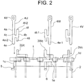
- FIG. 2 is a side view for illustrating the terminal device of FIG. 1 .
- a base 1 which is made of an insulating resin and has an annular shape, is fixed to an axial end of a stator (not shown).
- Annular grooves arranged in two rows, specifically, an outer groove 1a and an inner groove 1b are formed on a surface of the base 1, which is on the side opposite to the stator.
- a first connection-terminal support portion 1c, a second connection-terminal support portion 1d, and a third connection-terminal support portion 1e are provided at three positions on an outer periphery of the base 1.
- the first connection-terminal support portion 1c, the second connection-terminal support portion 1d, and the third connection-terminal support portion 1e are arranged at intervals in a circumferential direction of the base 1.
- a plurality of (twelve in this example) coil conductor end portions 2 drawn out from a plurality of stator windings (not shown) are arranged at intervals in the circumferential direction of the base 1.
- the coil conductor end portions 2 are connected in, for example, a Y-connection configuration or a A-connection configuration through intermediation of the terminal device.
- a U-phase conductive plate 3U, a V-phase conductive plate 3V, and a W-phase conductive plate 3W, each being a plate-shaped conductive member, are inserted into the outer groove 1a and the inner groove 1b.
- the U-phase conductive plate 3U includes a U-phase conductive plate main body 3Ua, a plurality of (four in this example) U-phase arm portions 3Ub, and a U-phase conductive plate-side connecting portion 3Uc.
- the U-phase conductive plate main body 3Ua is arranged in the outer groove 1a.
- Each of the U-phase arm portions 3Ub is arranged between a corresponding one of the coil conductive end portions 2 and the U-phase conductive plate main body 3Ua.
- the U-phase conductive plate-side connecting portion 3Uc which serves as a first connecting portion, has a rectangular flat plate shape and is arranged in the vicinity of the first connection-terminal support portion 1c.
- Each of the U-phase arm portions 3Ub projects from the outer groove 1a in an axial direction of the base 1 and also projects outward in a radial direction of the base 1. Further, a distal end of each of the U-phase arm portions 3Ub encloses the corresponding one of the coil conductive end portions 2 and is connected to the corresponding one of the coil conductive end portions 2 through fusing or welding.
- the V-phase conductive plate 3V includes a V-phase conductive plate main body 3Va, a plurality of (four in this example) V-phase arm portions 3Vb, and a V-phase conductive plate-side connecting portion 3Vc.
- the V-phase conductive plate main body 3Va is arranged over the outer groove 1a and the inner groove 1b.
- Each of the V-phase arm portions 3Vb is arranged between a corresponding one of the coil conductive end portions 2 and the V-phase conductive plate main body 3Va.
- the V-phase conductive plate-side connecting portion 3Vc which serves as a first connecting portion, has a rectangular flat plate shape and is arranged in the vicinity of the second connection-terminal support portion 1d.
- Each of the V-phase arm portions 3Vb projects from the outer groove 1a in an axial direction of the base 1 and also projects outward in a radial direction of the base 1. Further, a distal end of each of the V-phase arm portions 3Vb encloses the corresponding one of the coil conductive end portions 2 and is connected to the corresponding one of the coil conductive end portions 2 through fusing or welding.
- the W-phase conductive plate 3W includes a W-phase conductive plate main body 3Wa, a plurality of (four in this example) W-phase arm portions 3Wb, and a W-phase conductive plate-side connecting portion 3Wc.
- the W-phase conductive plate main body 3Wa is arranged in the inner groove 1b.
- Each of the W-phase arm portions 3Wb is arranged between a corresponding one of the coil conductive end portions 2 and the W-phase conductive plate main body 3Wa.
- the W-phase conductive plate-side connecting portion 3Wc which serves as a first connecting portion, has a rectangular flat plate shape and is arranged in the vicinity of the third connection-terminal support portion 1e.
- Each of the W-phase arm portions 3Wb projects from the outer groove 1a in an axial direction of the base 1 and also projects outward in a radial direction of the base 1. Further, a distal end of each of the W-phase arm portions 3Wb encloses the corresponding one of the coil conductive end portions 2 and is connected to the corresponding one of the coil conductive end portions 2 through fusing or welding.
- a U-phase connection terminal 4U, a V-phase connection terminal 4V, and a W-phase connection terminal 4W are supported in the first connection-terminal support portion 1c, the second connection-terminal support portion 1d, and the third connection-terminal support portion 1e, respectively.
- the U-phase connection terminal 4U, the V-phase connection terminal 4V, and the W-phase connection terminal 4W are illustrated as being separated from the base 1.
- Each of the U-phase connection terminal 4U, the V-phase connection terminal 4V, and the W-phase connection terminal 4W is formed of a common component. Specifically, each of the U-phase connection terminal 4U, the V-phase connection terminal 4V, and the W-phase connection terminal 4W is a component having the same shape, which is made of the same material.
- connection terminals 4U, 4V, and 4W is a component having a flat plate shape, and has a first straight portion 4a, a second straight portion 4b, and a bridge portion 4c.
- the second straight portion 4b is parallel to the first straight portion 4a.
- the bridge portion 4c is formed between the first straight portion 4a and the second straight portion 4b.
- a length of the second straight portion 4b is shorter than a length of the first straight portion 4a.
- a current supply portion 4d, to which a current is supplied, is formed at an end of the first straight portion 4a, which is on the side opposite to the base 1.
- a positioning insertion portion 4e is formed at an end of the first straight portion 4a, which is on the side closer to the base 1.
- An abutment portion 4g is formed at an end of the second straight portion 4b, which is on the side closer to the base 1.
- the terminal-side connecting portion 4f is not formed on the first straight portion 4a with the current supply portion 4d and is arranged at a position offset from the first straight portion 4a. Specifically, the terminal-side connecting portion 4f is nonlinearly continuous with the current supply portion 4d through the bridge portion 4c therebetween.
- connection-terminal support portions 1c, 1d, and 1e has a leg portion 5 and a hole 6.
- the leg portion 5 is configured to support the base 1 itself.
- the positioning insertion portion 4e is inserted into the hole 6.
- each of the positioning insertion portions 4e is inserted into a corresponding one of the holes 6 until the abutment portion 4g is brought into abutment against an upper surface of a corresponding one of the connection-terminal support portions 1c, 1d, and 1e.
- each of the connection terminals 4U, 4V, and 4W is arranged at an appropriate position in a corresponding one of the connection-terminal support portions 1c, 1d, and 1e.
- a width dimension of the hole 6 in a thickness direction of the positioning insertion portion 4e is equal to a thickness dimension of the positioning insertion portion 4e.
- the terminal-side connecting portion 4f is placed so as to be brought into full contact with a corresponding one of the conductive plate-side connecting portions 3Uc, 3Vc, and 3Wc. Under this state, the terminal-side connecting portion 4f is connected to the corresponding one of the conductive plate-side connecting portions 3Uc, 3Vc, and 3Wc through welding or soldering so as to be mechanically and electrically connected thereto.
- connection terminals 4U, 4V, and 4W are formed as members independent of the conductive plates 3U, 3V, and 3W so as to improve a yield of the material.
- the terminal-side connecting portion 4f has a connecting-portion front surface 4f-1 and a connecting-portion back surface 4f-2 located on a back side of the connecting-portion front surface 4f-1.
- the connecting-portion front surface 4f-1 is one end surface of the terminal-side connecting portion 4f in a thickness direction of the terminal-side connecting portion 4f
- the connecting-portion back surface 4f-2 is another end surface of the terminal-side connecting portion 4f in the thickness direction of the terminal-side connecting portion 4f.
- the positioning insertion portion 4e has an insertion-portion front surface 4e-1 and an insertion-portion back surface 4e-2 located on a back side of the insertion-portion front surface 4e-1.
- the insertion-portion front surface 4e-1 is one end surface of the positioning insertion portion 4e in a thickness direction of the positioning insertion portion 4e
- the insertion-portion back surface 4e-2 is another end surface of the positioning insertion portion 4e in the thickness direction of the positioning insertion portion 4e.
- a position of the hole 6 formed in the first connection-terminal support portion 1c in a circumferential direction of the base 1 is opposite to a position of the hole 6 formed in the second connection-terminal support portion 1d in the circumferential direction of the base 1.
- any one of the connecting-portion front surface 4f-1 and the connecting-portion back surface 4f-2 is selectively placed so as to be brought into full contact with a corresponding one of the conductive plate-side connecting portions 3Uc, 3Vc, and 3Wc.
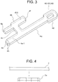
- FIG. 3 is a perspective view for illustrating the connection terminal 4U, 4V, 4W of FIG. 2 .
- two sets of inclined surfaces 4h are formed so that a width dimension and a thickness dimension of each thereof are gradually reduced toward the distal end of the positioning insertion portion 4e.
- a method of manufacturing the terminal device of the first embodiment is described.
- conductive flat plates are press-worked into a shape of the conductive plate 3U, 3V, 3W and a shape of the connection terminals 4U, 4V, 4W.
- a conductive flat plate for example, a copper plate 7 is press-worked, specifically, is subjected to shearing to form an intermediate body 7a.
- the intermediate body 7a of FIG. 4 is formed by cutting the copper plate 7 downward from a upper side of FIG. 4 .
- upper corners of the intermediate body 7a are rounded due to so-called “shear droop” .
- burr is formed at lower corners of the intermediate body 7a. Under a state in which the shear droop and the burr described above are formed, a front surface and a back surface of the intermediate body 7a are different from each other.
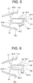
- compression processing is performed for both ends of the terminal-side connecting portion 4f in the width direction with a first die 11 and a second die 12.
- the first die 11 has a first compression surface 11a that is inclined with respect to the connecting-portion front surface 4f-1.
- the second die 12 has a second compression surface 12a that is inclined to the side opposite to the first compression surface 11a with respect to the connecting-portion back surface 4f-2.
- the connecting-portion front surface 4f-1 and the connecting-portion back surface 4f-2 of the terminal-side connecting portion 4f which serves as a processed connecting portion, gradually approach each other as extending outward in a width direction of the terminal-side connecting portion 4f at both ends of the terminal-side connecting portion 4f in the width direction.
- a pair of inclined surfaces 4f-3 and 4f-4 each having a tapered shape
- a pair of inclined surfaces 4f-5 and 4f-6 each having a tapered shape
- the inclined surface 4f-3 and the inclined surface 4f-4 are line-symmetric with respect to a center line C1 in the thickness direction of the terminal-side connecting portion 4f .
- the inclined surface 4f-5 and the inclined surface 4f-6 are line-symmetric with respect to the center line C1 in the thickness direction of the terminal-side connecting portion 4f.
- Similar compression processing is also performed for the positioning insertion portion 4e.
- the insertion-portion front surface 4e-1 and the insertion-portion back surface 4e-2 of the positioning insertion portion 4e gradually approach each other as extending outward in a width direction of the positioning insertion portion 4e at both ends of the positioning insertion portion 4e in the width direction.
- a pair of inclined surfaces 4e-3 and 4e-4 each having a tapered shape
- a pair of inclined surfaces 4e-5 and 4e-6 each having a tapered shape
- the inclined surface 4e-3 and the inclined surface 4e-4 are line-symmetric with respect to a center line C2 in the thickness direction of the positioning insertion portion 4e.
- the inclined surface 4e-5 and the inclined surface 4e-6 are line-symmetric with respect to the center line C2 in the thickness direction of the positioning insertion portion 4e.
- An inclination angle ⁇ 2 and an inclination range W2 of each of the insertion-portion front surface 4e-1 and the insertion-portion back surface 4e-2 at both ends of the positioning insertion portion 4e illustrated in FIG. 6 in the width direction are larger than an inclination angle ⁇ 1 and an inclination range W1 of each of the connecting-portion front surface 4f-1 and the connecting-portion back surface 4f-2 at both ends of the terminal-side connecting portion 4f illustrated in FIG. 5 in the width direction, respectively.
- the inclination angles ⁇ 1 and ⁇ 2 formed through the compression processing can be appropriately changed.
- the inclined surfaces 4h of the positioning insertion portion 4e in the width direction can be formed through press-working.
- the inclined surfaces 4h of the positioning insertion portion 4e in the thickness direction can be formed through the compression processing.
- the compression processing is performed for both surfaces at both ends of the terminal-side connecting portion 4f in the width direction and both surfaces at both ends of the positioning insertion portion 4e in the width direction.
- the shear droop and the burr formed in the press-working are removed to thereby form the connection terminals 4U, 4V, and 4W.
- the compression processing can be partially performed as needed.
- the conductive plates 3U, 3V, and 3W and the connection terminals 4U, 4V, and 4W are formed, the conductive plates 3U, 3V, and 3W are assembled into the base 1 and the connection terminals 4U, 4V, and 4W are mounted into the connection-terminal support portions 1c, 1d, and 1e, respectively.
- the terminal-side connecting portions 4f are connected to corresponding ones of the conductive plate-side connecting portions 3Uc, 3Vc, and 3Wc, respectively, to thereby manufacture the terminal device.
- connection terminals 4U, 4V, and 4W can be connected to the conductive plates 3U, 3V, and 3W without formation of the shear droop and the burr and need for checking the front side and the back side.
- manufacturing efficiency can be improved.
- the terminal device when an effective space cannot be ensured between the terminal-side connecting portion 4f and the arm portion 3Ub, 3Vb, 3Wb because of a positional relationship between the connection terminals 4U, 4V, and 4W and the arm portions 3Ub, 3Vb, and 3Wb, the terminal device is designed so that the connection terminal 4U, 4V, 4W is appropriately turned over. As a result, a sufficient space can be ensured. In this manner, a degree of freedom in design can be improved.
- connection terminals 4U, 4V, and 4W With the use of common components for the connection terminals 4U, 4V, and 4W, the number of kinds of components is reduced. As a result, cost can be reduced.
- connection terminals 4U, 4V, and 4W are mounted into the base 1 by an assembly device
- the U-phase connection terminal 4U and the V-phase connection terminal 4V can be gripped so as to be oriented in the same direction and be inserted into the hole 6 in the first connection-terminal support portion 1c and the hole 6 of the second connection-terminal support portion 1d, respectively.
- a mechanism for rotating the connection terminal by 180 degrees is not required to be provided to a gripping portion configured to grip the connection terminals 4U, 4V, and 4W.
- connection terminals 4U, 4V, and 4W has the positioning insertion portion 4e, and the holes 6 are formed in the base 1.
- the connection terminals 4U, 4V, and 4W can easily be positioned.
- connection terminals 4U, 4V, and 4W can be more accurately positioned.
- the inclination angle ⁇ 2 and the inclination range W2 of each of the insertion-portion front surface 4e-1 and the insertion-portion back surface 4e-2 at both ends of the positioning insertion portion 4e in the width direction are larger than the inclination angle ⁇ 1 and the inclination range W1 of each of the connecting-portion front surface 4f-1 and the connecting-portion back surface 4f-2 at both ends of the terminal-side connecting portion 4f in the width direction, respectively.
- the positioning insertion portions 4e can be more smoothly inserted into the holes 6.
- a joint area of the terminal-side connecting portion 4f to the conductive plate-side connecting portion 3Uc, 3Vc, 3Wc can be sufficiently ensured.
- the two sets of inclined surfaces 4h are formed at the distal end portion of each of the positioning insertion portions 4e.
- the positioning insertion portions 4e can be more smoothly inserted into the holes 6.
- terminal-side connecting portion 4f is nonlinearly continuous with the current supply portion 4d through intermediation of the bridge portion 4c.
- thermal conduction to the current supply portion 4d can be suppressed. Accordingly, even when an electric component is connected in advance to the current supply portion 4d, thermal conduction to the electric component can be suppressed.
- connection terminal 4U, 4V, 4W has the abutment portion 4g.
- tilt of the connection terminal 4U, 4V, 4W can be prevented.
- terminal-side connecting portions 4f can easily be positioned in a direction of inserting the positioning insertion portions 4e into the holes 6.
- the compression processing is performed for the terminal-side connecting portions 4f and the positioning insertion portions 4e.
- the compression processing for the positioning insertion portions 4e may be omitted.
- the compression processing may also be performed for the current supply portions 4d depending on a connection direction. There arises no problem even when the burr and the shear droop are present on other portion of the connection terminal 4U, 4V, 4W. Thus, the compression processing is not required to be performed.
- each of the inclined surfaces are formed through the compression processing.
- each of the inclined surfaces may be formed as a curved surface having roundness.
- the compression processing is performed for both surfaces of each of the terminal-side connecting portions 4f.
- the compression processing may be performed for both surfaces of each of the conductive plate-side connecting portions 3Uc, 3Vc, and 3Wc to which the terminal-side connecting portions 4f are connected.
- the compression processing may be performed only for the conductive plate-side connecting portions 3Uc, 3Vc, and 3Wc.
- the processed connecting portion is at least any one of the first connecting portion and the second connecting portion.
- the motor has been described as the rotary electric machine.
- the present invention is applicable also to, for example, a terminal device for a power generator or a motor generator.
Landscapes
- Engineering & Computer Science (AREA)
- Power Engineering (AREA)
- Manufacturing & Machinery (AREA)
- Manufacture Of Motors, Generators (AREA)
- Insulation, Fastening Of Motor, Generator Windings (AREA)
Abstract
Description
- The present invention relates to a terminal device to be provided in a rotary electric machine such as a motor and a method of manufacturing the same.
- In a related-art rotary electric machine, to each stator coil terminal, a corresponding terminal is connected. Each of the terminals has a rising portion. A plurality of feeding terminals are held in a base. Each of the feeding terminals is connected to a corresponding one of the rising portions through welding, fusing, or soldering (see, for example, Patent Literature 1) .
- [PTL 1]
JP 5320431 B2 - In general, components such as the terminals and the feeding terminals are manufactured by press-working. In the press-working, burr is formed at a processed portion. Thus, in the related-art rotary electric machine described above, when the feeding terminals are connected to the rising portions, attention is required so as to join surfaces, each without the burr projecting therefrom. Specifically, effort and time are required to check a front side and a back side of each of the components.
- The present invention has been made to solve the problems described above, and has an object to provide a terminal device for a rotary electric machine and a method of manufacturing the same, with which connection terminals can be connected to conductive members without need for checking a front side and a back side of each of the connection terminals to improve manufacturing efficiency.
- A terminal device for a rotary electric machine according to one embodiment of the present invention includes: a base made of an insulating material; a plurality of conductive members, which are provided to the base, and each have a first connecting portion having a flat plate shape; and a plurality of connection terminals, each having a second connecting portion having a flat plate shape, the second connecting portion to be connected to a corresponding one of the first connecting portions, wherein each of the first connecting portion and the second connecting portion has a connecting-portion front surface and a connecting-portion back surface being positioned on a back side of the connecting-portion front surface, wherein any one of the connecting-portion front surface and the connecting-portion back surface of each of the second connecting portions is selectively brought into full contact with a corresponding one of the first connecting portions, and wherein the connecting-portion front surface and the connecting-portion back surface of a processed connecting portion being at least any one of the first connecting portion and the second connecting portion gradually approach each other as extending outward in a width direction of the processed connecting portion at both ends of the processed connecting portion in the width direction of the processed connecting portion.
- A method of manufacturing a terminal device for a rotary electric machine, the terminal device including: a base made of an insulating material; a plurality of conductive members, which are provided to the base, and each have a first connecting portion having a flat plate shape; and a plurality of connection terminals, each having a second connecting portion having a flat plate shape, the second connecting portion to be connected to a corresponding one of the first connecting portions, the method comprising: forming a processed connecting portion being at least any one of the first connecting portion and the second connecting portion through press-working for a conductive flat plate; and performing compression processing for a front surface and a back surface of the processed connecting portion at both ends of the processed connecting portion in a width direction of the processed connecting portion.
- With the terminal device for a rotary electric machine of the present invention, connection terminals can be connected to conductive members without need for checking a front side and a back side of each of the connection terminals, thereby being capable of improving manufacturing efficiency.
-
-
FIG. 1 is a plan view for illustrating a terminal device for a motor according to a first embodiment of the present invention. -
FIG. 2 is a side view for illustrating the terminal device ofFIG. 1 . -
FIG. 3 is a perspective view for illustrating a U-phase connection terminal, a V-phase connection terminal, and a W-phase connection terminal ofFIG. 2 . -
FIG. 4 is an explanatory view for illustrating a method of manufacturing the U-phase connection terminal, the V-phase connection terminal, and the W-phase connection terminal ofFIG. 2 . -
FIG. 5 is an explanatory view for illustrating a state in which compression processing is performed for a terminal-side connecting portion of an intermediate body ofFIG. 4 . -
FIG. 6 is an explanatory view for illustrating a state in which compression processing is performed for a positioning insertion portion of the intermediate body ofFIG. 4 . - Now, embodiments of the present invention are described with reference to the drawings.
-
FIG. 1 is a plan view for illustrating a terminal device for a motor according to a first embodiment of the present invention.FIG. 2 is a side view for illustrating the terminal device ofFIG. 1 . InFIG. 1 andFIG. 2 , abase 1, which is made of an insulating resin and has an annular shape, is fixed to an axial end of a stator (not shown). Annular grooves arranged in two rows, specifically, anouter groove 1a and aninner groove 1b are formed on a surface of thebase 1, which is on the side opposite to the stator. - A first connection-
terminal support portion 1c, a second connection-terminal support portion 1d, and a third connection-terminal support portion 1e are provided at three positions on an outer periphery of thebase 1. The first connection-terminal support portion 1c, the second connection-terminal support portion 1d, and the third connection-terminal support portion 1e are arranged at intervals in a circumferential direction of thebase 1. - On a radially outer side of the
base 1, a plurality of (twelve in this example) coilconductor end portions 2 drawn out from a plurality of stator windings (not shown) are arranged at intervals in the circumferential direction of thebase 1. The coilconductor end portions 2 are connected in, for example, a Y-connection configuration or a A-connection configuration through intermediation of the terminal device. - A U-phase
conductive plate 3U, a V-phaseconductive plate 3V, and a W-phaseconductive plate 3W, each being a plate-shaped conductive member, are inserted into theouter groove 1a and theinner groove 1b. - The U-phase
conductive plate 3U includes a U-phase conductive plate main body 3Ua, a plurality of (four in this example) U-phase arm portions 3Ub, and a U-phase conductive plate-side connecting portion 3Uc. The U-phase conductive plate main body 3Ua is arranged in theouter groove 1a. Each of the U-phase arm portions 3Ub is arranged between a corresponding one of the coilconductive end portions 2 and the U-phase conductive plate main body 3Ua. The U-phase conductive plate-side connecting portion 3Uc, which serves as a first connecting portion, has a rectangular flat plate shape and is arranged in the vicinity of the first connection-terminal support portion 1c. - Each of the U-phase arm portions 3Ub projects from the
outer groove 1a in an axial direction of thebase 1 and also projects outward in a radial direction of thebase 1. Further, a distal end of each of the U-phase arm portions 3Ub encloses the corresponding one of the coilconductive end portions 2 and is connected to the corresponding one of the coilconductive end portions 2 through fusing or welding. - The V-phase
conductive plate 3V includes a V-phase conductive plate main body 3Va, a plurality of (four in this example) V-phase arm portions 3Vb, and a V-phase conductive plate-side connecting portion 3Vc. The V-phase conductive plate main body 3Va is arranged over theouter groove 1a and theinner groove 1b. Each of the V-phase arm portions 3Vb is arranged between a corresponding one of the coilconductive end portions 2 and the V-phase conductive plate main body 3Va. The V-phase conductive plate-side connecting portion 3Vc, which serves as a first connecting portion, has a rectangular flat plate shape and is arranged in the vicinity of the second connection-terminal support portion 1d. - Each of the V-phase arm portions 3Vb projects from the
outer groove 1a in an axial direction of thebase 1 and also projects outward in a radial direction of thebase 1. Further, a distal end of each of the V-phase arm portions 3Vb encloses the corresponding one of the coilconductive end portions 2 and is connected to the corresponding one of the coilconductive end portions 2 through fusing or welding. - The W-phase
conductive plate 3W includes a W-phase conductive plate main body 3Wa, a plurality of (four in this example) W-phase arm portions 3Wb, and a W-phase conductive plate-side connecting portion 3Wc. The W-phase conductive plate main body 3Wa is arranged in theinner groove 1b. Each of the W-phase arm portions 3Wb is arranged between a corresponding one of the coilconductive end portions 2 and the W-phase conductive plate main body 3Wa. The W-phase conductive plate-side connecting portion 3Wc, which serves as a first connecting portion, has a rectangular flat plate shape and is arranged in the vicinity of the third connection-terminal support portion 1e. - Each of the W-phase arm portions 3Wb projects from the
outer groove 1a in an axial direction of thebase 1 and also projects outward in a radial direction of thebase 1. Further, a distal end of each of the W-phase arm portions 3Wb encloses the corresponding one of the coilconductive end portions 2 and is connected to the corresponding one of the coilconductive end portions 2 through fusing or welding. - A
U-phase connection terminal 4U, a V-phase connection terminal 4V, and a W-phase connection terminal 4W (none of those is shown inFIG. 1 ) are supported in the first connection-terminal support portion 1c, the second connection-terminal support portion 1d, and the third connection-terminal support portion 1e, respectively. InFIG. 2 , theU-phase connection terminal 4U, the V-phase connection terminal 4V, and the W-phase connection terminal 4W are illustrated as being separated from thebase 1. - Each of the
U-phase connection terminal 4U, the V-phase connection terminal 4V, and the W-phase connection terminal 4W is formed of a common component. Specifically, each of theU-phase connection terminal 4U, the V-phase connection terminal 4V, and the W-phase connection terminal 4W is a component having the same shape, which is made of the same material. - Each of the
connection terminals straight portion 4a, a secondstraight portion 4b, and abridge portion 4c. The secondstraight portion 4b is parallel to the firststraight portion 4a. Thebridge portion 4c is formed between the firststraight portion 4a and the secondstraight portion 4b. A length of the secondstraight portion 4b is shorter than a length of the firststraight portion 4a. - A
current supply portion 4d, to which a current is supplied, is formed at an end of the firststraight portion 4a, which is on the side opposite to thebase 1. Apositioning insertion portion 4e is formed at an end of the firststraight portion 4a, which is on the side closer to thebase 1. - A terminal-
side connecting portion 4f having a rectangular flat plate shape, which serves as a second connecting portion, is formed at an end of the secondstraight portion 4b, which is on the side opposite to thebase 1. Anabutment portion 4g is formed at an end of the secondstraight portion 4b, which is on the side closer to thebase 1. - The terminal-
side connecting portion 4f is not formed on the firststraight portion 4a with thecurrent supply portion 4d and is arranged at a position offset from the firststraight portion 4a. Specifically, the terminal-side connecting portion 4f is nonlinearly continuous with thecurrent supply portion 4d through thebridge portion 4c therebetween. - Each of the connection-
terminal support portions leg portion 5 and ahole 6. Theleg portion 5 is configured to support thebase 1 itself. Thepositioning insertion portion 4e is inserted into thehole 6. - Each of the
positioning insertion portions 4e is inserted into a corresponding one of theholes 6 until theabutment portion 4g is brought into abutment against an upper surface of a corresponding one of the connection-terminal support portions connection terminals terminal support portions - A width dimension of the
hole 6 in a thickness direction of thepositioning insertion portion 4e is equal to a thickness dimension of thepositioning insertion portion 4e. With the above-mentioned width dimensions, thepositioning insertion portion 4e is inserted into thehole 6 in a press-fitted state. - As a result of the appropriate insertion of the
positioning insertion portion 4e into thehole 6, the terminal-side connecting portion 4f is placed so as to be brought into full contact with a corresponding one of the conductive plate-side connecting portions 3Uc, 3Vc, and 3Wc. Under this state, the terminal-side connecting portion 4f is connected to the corresponding one of the conductive plate-side connecting portions 3Uc, 3Vc, and 3Wc through welding or soldering so as to be mechanically and electrically connected thereto. - The
connection terminals conductive plates - In
FIG. 2 , theU-phase connection terminal 4U is illustrated with the right and the left reversed to those of the V-phase connection terminal 4V and the W-phase connection terminal 4W. The terminal-side connecting portion 4f has a connecting-portion front surface 4f-1 and a connecting-portion backsurface 4f-2 located on a back side of the connecting-portion front surface 4f-1. The connecting-portion front surface 4f-1 is one end surface of the terminal-side connecting portion 4f in a thickness direction of the terminal-side connecting portion 4f, whereas the connecting-portion backsurface 4f-2 is another end surface of the terminal-side connecting portion 4f in the thickness direction of the terminal-side connecting portion 4f. - The
positioning insertion portion 4e has an insertion-portion front surface 4e-1 and an insertion-portion backsurface 4e-2 located on a back side of the insertion-portion front surface 4e-1. The insertion-portion front surface 4e-1 is one end surface of thepositioning insertion portion 4e in a thickness direction of thepositioning insertion portion 4e, whereas the insertion-portion backsurface 4e-2 is another end surface of thepositioning insertion portion 4e in the thickness direction of thepositioning insertion portion 4e. - In
FIG. 1 , a position of thehole 6 formed in the first connection-terminal support portion 1c in a circumferential direction of thebase 1 is opposite to a position of thehole 6 formed in the second connection-terminal support portion 1d in the circumferential direction of thebase 1. Under a state in which theconnection terminals base 1, any one of the connecting-portion front surface 4f-1 and the connecting-portion backsurface 4f-2 is selectively placed so as to be brought into full contact with a corresponding one of the conductive plate-side connecting portions 3Uc, 3Vc, and 3Wc. -
FIG. 3 is a perspective view for illustrating theconnection terminal FIG. 2 . At both ends of a distal end portion of thepositioning insertion portion 4e in a width direction of thepositioning insertion portion 4e and both ends thereof in a thickness direction, two sets ofinclined surfaces 4h, each having a tapered shape, are formed so that a width dimension and a thickness dimension of each thereof are gradually reduced toward the distal end of thepositioning insertion portion 4e. - Next, a method of manufacturing the terminal device of the first embodiment is described. When the
conductive plates connection terminals conductive plate connection terminals connection terminal FIG. 4 , a conductive flat plate, for example, acopper plate 7 is press-worked, specifically, is subjected to shearing to form anintermediate body 7a. - The
intermediate body 7a ofFIG. 4 is formed by cutting thecopper plate 7 downward from a upper side ofFIG. 4 . As a result, upper corners of theintermediate body 7a are rounded due to so-called "shear droop" . At lower corners of theintermediate body 7a, so-called "burr" is formed. Under a state in which the shear droop and the burr described above are formed, a front surface and a back surface of theintermediate body 7a are different from each other. - In particular, when a surface of the terminal-
side connecting portion 4f, on which the burr is formed, is brought into full contact with the conductive plate-side connecting portion 3Uc, 3Vc, 3Wc while protrusions formed due to the burr remain, a gap is defined therebetween. - Meanwhile, in this embodiment, as illustrated in
FIG. 5 , compression processing is performed for both ends of the terminal-side connecting portion 4f in the width direction with afirst die 11 and asecond die 12. Thefirst die 11 has afirst compression surface 11a that is inclined with respect to the connecting-portion front surface 4f-1. Thesecond die 12 has asecond compression surface 12a that is inclined to the side opposite to thefirst compression surface 11a with respect to the connecting-portion backsurface 4f-2. - Through the compression processing described above, the connecting-
portion front surface 4f-1 and the connecting-portion backsurface 4f-2 of the terminal-side connecting portion 4f, which serves as a processed connecting portion, gradually approach each other as extending outward in a width direction of the terminal-side connecting portion 4f at both ends of the terminal-side connecting portion 4f in the width direction. - Specifically, at one end of the terminal-
side connecting portion 4f in the width direction, a pair ofinclined surfaces 4f-3 and 4f-4, each having a tapered shape, is formed. At another end of the terminal-side connecting portion 4f in the width direction, a pair ofinclined surfaces 4f-5 and 4f-6, each having a tapered shape, is formed. - The
inclined surface 4f-3 and theinclined surface 4f-4 are line-symmetric with respect to a center line C1 in the thickness direction of the terminal-side connecting portion 4f . Theinclined surface 4f-5 and theinclined surface 4f-6 are line-symmetric with respect to the center line C1 in the thickness direction of the terminal-side connecting portion 4f. - Further, as illustrated in
FIG. 6 , similar compression processing is also performed for thepositioning insertion portion 4e. Through the compression processing described above, the insertion-portion front surface 4e-1 and the insertion-portion backsurface 4e-2 of thepositioning insertion portion 4e gradually approach each other as extending outward in a width direction of thepositioning insertion portion 4e at both ends of thepositioning insertion portion 4e in the width direction. - Specifically, at one end of the
positioning insertion portion 4e in the width direction, a pair ofinclined surfaces 4e-3 and 4e-4, each having a tapered shape, is formed. At another end of thepositioning insertion portion 4e in the width direction, a pair ofinclined surfaces 4e-5 and 4e-6, each having a tapered shape, is formed. - The
inclined surface 4e-3 and theinclined surface 4e-4 are line-symmetric with respect to a center line C2 in the thickness direction of thepositioning insertion portion 4e. Theinclined surface 4e-5 and theinclined surface 4e-6 are line-symmetric with respect to the center line C2 in the thickness direction of thepositioning insertion portion 4e. - An inclination angle θ2 and an inclination range W2 of each of the insertion-
portion front surface 4e-1 and the insertion-portion backsurface 4e-2 at both ends of thepositioning insertion portion 4e illustrated inFIG. 6 in the width direction are larger than an inclination angle θ1 and an inclination range W1 of each of the connecting-portion front surface 4f-1 and the connecting-portion backsurface 4f-2 at both ends of the terminal-side connecting portion 4f illustrated inFIG. 5 in the width direction, respectively. The inclination angles θ1 and θ2 formed through the compression processing can be appropriately changed. - The
inclined surfaces 4h of thepositioning insertion portion 4e in the width direction can be formed through press-working. Theinclined surfaces 4h of thepositioning insertion portion 4e in the thickness direction can be formed through the compression processing. - As described above, after the terminal-
side connecting portion 4f and thepositioning insertion portion 4e are formed through the press-working, the compression processing is performed for both surfaces at both ends of the terminal-side connecting portion 4f in the width direction and both surfaces at both ends of thepositioning insertion portion 4e in the width direction. As a result, the shear droop and the burr formed in the press-working are removed to thereby form theconnection terminals - Even for the
conductive plates conductive plates connection terminals conductive plates base 1 and theconnection terminals terminal support portions side connecting portions 4f are connected to corresponding ones of the conductive plate-side connecting portions 3Uc, 3Vc, and 3Wc, respectively, to thereby manufacture the terminal device. - With the terminal device for a rotary electric machine and the method of manufacturing the terminal device described above, the compression processing, specifically, edge-rounding is performed for both surfaces, specifically, the connecting-
portion front surface 4f-1 and the connecting-portion backsurface 4f-2. Thus, theconnection terminals conductive plates - For example, when an effective space cannot be ensured between the terminal-
side connecting portion 4f and the arm portion 3Ub, 3Vb, 3Wb because of a positional relationship between theconnection terminals connection terminal - Further, with the use of common components for the
connection terminals - Further, when the
connection terminals base 1 by an assembly device, theU-phase connection terminal 4U and the V-phase connection terminal 4V can be gripped so as to be oriented in the same direction and be inserted into thehole 6 in the first connection-terminal support portion 1c and thehole 6 of the second connection-terminal support portion 1d, respectively. Thus, a mechanism for rotating the connection terminal by 180 degrees is not required to be provided to a gripping portion configured to grip theconnection terminals - Further, each of the
connection terminals positioning insertion portion 4e, and theholes 6 are formed in thebase 1. Thus, theconnection terminals - Further, similar compression processing to that performed for the terminal-
side connecting portions 4f is performed for thepositioning insertion portions 4e. Thus, thepositioning insertion portions 4e can be smoothly inserted into theholes 6 without being caught. As a result, theconnection terminals - Further, the inclination angle θ2 and the inclination range W2 of each of the insertion-
portion front surface 4e-1 and the insertion-portion backsurface 4e-2 at both ends of thepositioning insertion portion 4e in the width direction are larger than the inclination angle θ1 and the inclination range W1 of each of the connecting-portion front surface 4f-1 and the connecting-portion backsurface 4f-2 at both ends of the terminal-side connecting portion 4f in the width direction, respectively. Thus, thepositioning insertion portions 4e can be more smoothly inserted into theholes 6. Further, a joint area of the terminal-side connecting portion 4f to the conductive plate-side connecting portion 3Uc, 3Vc, 3Wc can be sufficiently ensured. - Further, the two sets of
inclined surfaces 4h, each having a tapered shape, are formed at the distal end portion of each of thepositioning insertion portions 4e. Thus, thepositioning insertion portions 4e can be more smoothly inserted into theholes 6. - Further, the terminal-
side connecting portion 4f is nonlinearly continuous with thecurrent supply portion 4d through intermediation of thebridge portion 4c. Thus, even when the terminal-side connecting portion 4f is connected to the conductive plate-side connecting portion 3Uc, 3Vc, 3Wc through, for example, welding, thermal conduction to thecurrent supply portion 4d can be suppressed. Accordingly, even when an electric component is connected in advance to thecurrent supply portion 4d, thermal conduction to the electric component can be suppressed. - Further, the
connection terminal abutment portion 4g. Thus, tilt of theconnection terminal side connecting portions 4f can easily be positioned in a direction of inserting thepositioning insertion portions 4e into theholes 6. - In the example described above, the compression processing is performed for the terminal-
side connecting portions 4f and thepositioning insertion portions 4e. However, the compression processing for thepositioning insertion portions 4e may be omitted. Further, the compression processing may also be performed for thecurrent supply portions 4d depending on a connection direction. There arises no problem even when the burr and the shear droop are present on other portion of theconnection terminal - In the example described above, the inclined surfaces, each being a flat surface, are formed through the compression processing. However, each of the inclined surfaces may be formed as a curved surface having roundness.
- In the example described above, the compression processing is performed for both surfaces of each of the terminal-
side connecting portions 4f. However, the compression processing may be performed for both surfaces of each of the conductive plate-side connecting portions 3Uc, 3Vc, and 3Wc to which the terminal-side connecting portions 4f are connected. Further, the compression processing may be performed only for the conductive plate-side connecting portions 3Uc, 3Vc, and 3Wc. As compared to a case in which the compression processing is performed for none of the terminal-side connecting portions 4f and the conductive plate-side connecting portions 3Uc, 3Vc, and 3Wc, the effects of the present invention can be obtained. Specifically, the processed connecting portion is at least any one of the first connecting portion and the second connecting portion. - Still further, in the example described above, the motor has been described as the rotary electric machine. However, the present invention is applicable also to, for example, a terminal device for a power generator or a motor generator.
- 1 base, 3U U-phase conductive plate (conductive member), 3Uc U-phase conductive plate-side connecting portion (first connecting portion), 3V V-phase conductive plate (conductive member), 3Vc V-phase conductive plate-side connecting portion (first connecting portion), 3W W-phase conductive plate (conductive member), 3Wc W-phase conductive plate-side connecting portion (first connecting portion), 4U U-phase connection terminal, 4V V-phase connection terminal, 4W W-phase connection terminal, 4c bridge portion, 4d current supply portion, 4e positioning insertion portion, 4e-1 insertion-portion front surface, 4e-2 insertion-portion back surface, 4f terminal-side connecting portion (second connecting portion), 4f-1 connecting-portion front surface, 4f-2 connecting-portion back surface, 4h inclined surface, 6 hole
Claims (9)
- A terminal device for a rotary electric machine, comprising:a base made of an insulating material;a plurality of conductive members, which are provided to the base, and each have a first connecting portion having a flat plate shape; anda plurality of connection terminals, each having a second connecting portion having a flat plate shape, the second connecting portion to be connected to a corresponding one of the first connecting portions,wherein each of the first connecting portion and the second connecting portion has a connecting-portion front surface and a connecting-portion back surface being positioned on a back side of the connecting-portion front surface,wherein any one of the connecting-portion front surface and the connecting-portion back surface of each of the second connecting portions is selectively brought into full contact with a corresponding one of the first connecting portions, andwherein the connecting-portion front surface and the connecting-portion back surface of a processed connecting portion being at least any one of the first connecting portion and the second connecting portion gradually approach each other as extending outward in a width direction of the processed connecting portion at both ends of the processed connecting portion in the width direction of the processed connecting portion.
- The terminal device for a rotary electric machine according to claim 1,
wherein the base has a plurality of holes,
wherein each of the connection terminals further has a positioning insertion portion to be inserted into a corresponding one of the plurality of holes, and
wherein the second connecting portions are respectively brought into full contact with the first connecting portions through insertion of the positioning insertion portions into the holes, respectively. - The terminal device for a rotary electric machine according to claim 2,
wherein each of the positioning insertion portions has an insertion-portion front surface and an insertion-portion back surface being positioned on a back side of the insertion-portion front surface, and
wherein the insertion-portion front surface and the insertion-portion back surface of each of the positioning insertion portions gradually approach each other as extending outward in a width direction of the positioning insertion portion at both ends of the positioning insertion portion in the width direction of the positioning insertion portion. - The terminal device for a rotary electric machine according to claim 3,
wherein each of the connecting-portion front surface and the connecting-portion back surface is inclined in a tapered manner at both ends of the processed connecting portion in the width direction of the processed connecting portion, and each of the insertion-portion front surface and the insertion-portion back surface is inclined in a tapered manner at both ends of the positioning insertion portion in the width direction, and
wherein an inclination angle of each of the connecting-portion front surface and the connecting-portion back surface at the both ends of the processed connecting portion in the width direction is different from an inclination angle of each of the insertion-portion front surface and the insertion-portion back surface at the both ends of the positioning insertion portion in the width direction. - The terminal device for a rotary electric machine according to claim 4, wherein the inclination angle and an inclination range of each of the insertion-portion front surface and the insertion-portion back surface at the both ends of the positioning insertion portion in the width direction are larger than the inclination angle and an inclination range of each of the connecting-portion front surface and the connecting-portion back surface at the both ends of the processed connecting portion in the width direction, respectively.
- The terminal device for a rotary electric machine according to any one of claims 2 to 5, wherein two sets of inclined surfaces, each having a tapered shape, are formed at a distal end portion of each of the positioning insertion portions so that a width dimension and a thickness dimension of each of the inclined surfaces gradually decrease in a direction toward the distal end of the corresponding one of the positioning insertion portions.
- The terminal device for a rotary electric machine according to any one of claims 1 to 6,
wherein each of the connection terminals further has a current supply portion, and
wherein each of the second connecting portions is nonlinearly continuous with a corresponding one of the current supply portions. - A method of manufacturing a terminal device for a rotary electric machine,
the terminal device comprising:a base made of an insulating material;a plurality of conductive members, which are provided to the base, and each have a first connecting portion having a flat plate shape; anda plurality of connection terminals, each having a second connecting portion having a flat plate shape, the second connecting portion to be connected to a corresponding one of the first connecting portions,the method comprising:forming a processed connecting portion being at least any one of the first connecting portion and the second connecting portion through press-working for a conductive flat plate; andperforming compression processing for a front surface and a back surface of the processed connecting portion at both ends of the processed connecting portion in a width direction of the processed connecting portion. - The method of manufacturing a terminal device for a rotary electric machine according to claim 8,
wherein the base has a plurality of holes,
wherein each of the connection terminals further has a positioning insertion portion to be inserted into a corresponding one of the plurality of holes, and
wherein the method further comprises:forming the positioning insertion portion through the press-working; andperforming the compression processing for a front surface and a back surface of the positioning insertion portion at both ends of the positioning insertion portion in a width direction of the positioning insertion portion.
Applications Claiming Priority (1)
| Application Number | Priority Date | Filing Date | Title |
|---|---|---|---|
| PCT/JP2017/013293 WO2018179242A1 (en) | 2017-03-30 | 2017-03-30 | Terminal device for dynamo-electric machine, and method for manufacturing same |
Publications (2)
| Publication Number | Publication Date |
|---|---|
| EP3605800A1 true EP3605800A1 (en) | 2020-02-05 |
| EP3605800A4 EP3605800A4 (en) | 2020-03-25 |
Family
ID=63674361
Family Applications (1)
| Application Number | Title | Priority Date | Filing Date |
|---|---|---|---|
| EP17903203.2A Withdrawn EP3605800A4 (en) | 2017-03-30 | 2017-03-30 | TERMINAL DEVICE FOR A DYNAMO-ELECTRIC MACHINE AND MANUFACTURING METHOD THEREOF |
Country Status (5)
| Country | Link |
|---|---|
| US (1) | US11316398B2 (en) |
| EP (1) | EP3605800A4 (en) |
| JP (1) | JPWO2018179242A1 (en) |
| CN (1) | CN110462988A (en) |
| WO (1) | WO2018179242A1 (en) |
Families Citing this family (1)
| Publication number | Priority date | Publication date | Assignee | Title |
|---|---|---|---|---|
| US11196316B2 (en) * | 2017-03-31 | 2021-12-07 | Nidec Corporation | Motor and electric power steering apparatus |
Family Cites Families (9)
| Publication number | Priority date | Publication date | Assignee | Title |
|---|---|---|---|---|
| JPS5238374A (en) | 1975-09-23 | 1977-03-24 | Matsuyama Kk | Apparatus for preparing fodder |
| JP2001095201A (en) | 1999-09-24 | 2001-04-06 | Toyoda Mach Works Ltd | Connecting method for motor |
| JP2004120905A (en) | 2002-09-26 | 2004-04-15 | Fuji Heavy Ind Ltd | Crossover structure of motor and stator structure using the crossover structure |
| JP5320431B2 (en) | 2011-04-27 | 2013-10-23 | 三菱電機株式会社 | Rotating electric machine |
| WO2013030913A1 (en) * | 2011-08-29 | 2013-03-07 | 三菱電機株式会社 | Rotating electric machine and method for manufacturing same |
| US20140183993A1 (en) * | 2011-09-22 | 2014-07-03 | Akira Takasaki | Stator of rotary electric machine |
| JP5282153B1 (en) * | 2012-03-30 | 2013-09-04 | 日本航空電子工業株式会社 | Resolver stator and method of manufacturing stator assembly |
| JP5980259B2 (en) * | 2014-03-12 | 2016-08-31 | 三菱電機株式会社 | Stator connection terminals and stator |
| WO2018038161A1 (en) * | 2016-08-23 | 2018-03-01 | 日本精工株式会社 | Terminal connection component, and terminal connection structure using same for connecting control device and motor |
-
2017
- 2017-03-30 WO PCT/JP2017/013293 patent/WO2018179242A1/en not_active Ceased
- 2017-03-30 US US16/489,171 patent/US11316398B2/en active Active
- 2017-03-30 EP EP17903203.2A patent/EP3605800A4/en not_active Withdrawn
- 2017-03-30 CN CN201780088580.6A patent/CN110462988A/en not_active Withdrawn
- 2017-03-30 JP JP2019508026A patent/JPWO2018179242A1/en active Pending
Also Published As
| Publication number | Publication date |
|---|---|
| US20200014269A1 (en) | 2020-01-09 |
| US11316398B2 (en) | 2022-04-26 |
| CN110462988A (en) | 2019-11-15 |
| WO2018179242A1 (en) | 2018-10-04 |
| EP3605800A4 (en) | 2020-03-25 |
| JPWO2018179242A1 (en) | 2019-11-07 |
Similar Documents
| Publication | Publication Date | Title |
|---|---|---|
| US11277047B2 (en) | Busbar apparatus, motor, and method of manufacturing busbar apparatus | |
| US20210050760A1 (en) | Motor | |
| CN101728888B (en) | Wiring component for motor coil | |
| CN109792187B (en) | Method for electrically contacting a winding of an electric machine with a printed circuit board | |
| US20180241272A1 (en) | Motor | |
| US20110018376A1 (en) | Busbar terminal, busbar unit, and motor | |
| US9362796B2 (en) | Electricity collection and distribution ring and electric motor | |
| US11183899B2 (en) | Stator for an electric machine, an electric machine and method for manufacturing such an electric machine | |
| CN101227117A (en) | Insulated case for motor | |
| CN110476331A (en) | Bus bar unit and motor with the bus bar unit | |
| US20160365761A1 (en) | Bus ring unit | |
| CN114977677B (en) | Busbar unit, stator and motor | |
| CN108899465B (en) | Battery for vehicle and method | |
| EP3605800A1 (en) | Terminal device for dynamo-electric machine, and method for manufacturing same | |
| CN112673547B (en) | motor | |
| CN105322681A (en) | Power supply apparatus for vehicle and insulation structure applied to same | |
| US12126235B2 (en) | Motor | |
| US20230132168A1 (en) | Motor | |
| WO2015040943A1 (en) | Bus ring | |
| CN113169616B (en) | Electric motor | |
| US20210066986A1 (en) | Arrangement structure of wiring member for rotating electrical machine | |
| JP2021111998A (en) | Stator | |
| US20240204585A1 (en) | Motor | |
| US20250038609A1 (en) | Armature and rotating electrical machine | |
| WO2025192435A1 (en) | Connecting structure, and stator for rotary electric machine employing same |
Legal Events
| Date | Code | Title | Description |
|---|---|---|---|
| PUAI | Public reference made under article 153(3) epc to a published international application that has entered the european phase |
Free format text: ORIGINAL CODE: 0009012 |
|
| 17P | Request for examination filed |
Effective date: 20190813 |
|
| AK | Designated contracting states |
Kind code of ref document: A1 Designated state(s): AL AT BE BG CH CY CZ DE DK EE ES FI FR GB GR HR HU IE IS IT LI LT LU LV MC MK MT NL NO PL PT RO RS SE SI SK SM TR |
|
| AX | Request for extension of the european patent |
Extension state: BA ME |
|
| A4 | Supplementary search report drawn up and despatched |
Effective date: 20200221 |
|
| RIC1 | Information provided on ipc code assigned before grant |
Ipc: H02K 5/22 20060101ALI20200217BHEP Ipc: H02K 3/50 20060101AFI20200217BHEP Ipc: H02K 15/04 20060101ALI20200217BHEP Ipc: H02K 3/52 20060101ALI20200217BHEP |
|
| DAV | Request for validation of the european patent (deleted) | ||
| DAX | Request for extension of the european patent (deleted) | ||
| 17Q | First examination report despatched |
Effective date: 20200708 |
|
| STAA | Information on the status of an ep patent application or granted ep patent |
Free format text: STATUS: THE APPLICATION HAS BEEN WITHDRAWN |
|
| 18W | Application withdrawn |
Effective date: 20200907 |