EP3605795A1 - Stator fixation structure and driving unit - Google Patents
Stator fixation structure and driving unit Download PDFInfo
- Publication number
- EP3605795A1 EP3605795A1 EP19197988.9A EP19197988A EP3605795A1 EP 3605795 A1 EP3605795 A1 EP 3605795A1 EP 19197988 A EP19197988 A EP 19197988A EP 3605795 A1 EP3605795 A1 EP 3605795A1
- Authority
- EP
- European Patent Office
- Prior art keywords
- stator
- wire rod
- bent wire
- axis
- along
- Prior art date
- Legal status (The legal status is an assumption and is not a legal conclusion. Google has not performed a legal analysis and makes no representation as to the accuracy of the status listed.)
- Granted
Links
- 230000002093 peripheral effect Effects 0.000 claims abstract description 21
- 230000000903 blocking effect Effects 0.000 claims abstract description 6
- 238000003825 pressing Methods 0.000 claims abstract description 6
- 238000010276 construction Methods 0.000 description 17
- 238000005452 bending Methods 0.000 description 7
- 230000035939 shock Effects 0.000 description 5
- 239000000853 adhesive Substances 0.000 description 4
- 230000001070 adhesive effect Effects 0.000 description 4
- 230000015572 biosynthetic process Effects 0.000 description 3
- 230000008878 coupling Effects 0.000 description 3
- 238000010168 coupling process Methods 0.000 description 3
- 238000005859 coupling reaction Methods 0.000 description 3
- 230000001629 suppression Effects 0.000 description 3
- 229910000831 Steel Inorganic materials 0.000 description 2
- 238000012986 modification Methods 0.000 description 2
- 230000004048 modification Effects 0.000 description 2
- 230000000284 resting effect Effects 0.000 description 2
- 239000010959 steel Substances 0.000 description 2
- 230000004308 accommodation Effects 0.000 description 1
- 230000007423 decrease Effects 0.000 description 1
- 230000003247 decreasing effect Effects 0.000 description 1
- 238000001514 detection method Methods 0.000 description 1
- 230000000694 effects Effects 0.000 description 1
- 238000004519 manufacturing process Methods 0.000 description 1
- 239000002184 metal Substances 0.000 description 1
- 238000000034 method Methods 0.000 description 1
- 238000005549 size reduction Methods 0.000 description 1
- 229910001220 stainless steel Inorganic materials 0.000 description 1
- 239000010935 stainless steel Substances 0.000 description 1
- 238000004804 winding Methods 0.000 description 1
Images


Classifications
-
- H—ELECTRICITY
- H02—GENERATION; CONVERSION OR DISTRIBUTION OF ELECTRIC POWER
- H02K—DYNAMO-ELECTRIC MACHINES
- H02K5/00—Casings; Enclosures; Supports
- H02K5/04—Casings or enclosures characterised by the shape, form or construction thereof
-
- B—PERFORMING OPERATIONS; TRANSPORTING
- B60—VEHICLES IN GENERAL
- B60L—PROPULSION OF ELECTRICALLY-PROPELLED VEHICLES; SUPPLYING ELECTRIC POWER FOR AUXILIARY EQUIPMENT OF ELECTRICALLY-PROPELLED VEHICLES; ELECTRODYNAMIC BRAKE SYSTEMS FOR VEHICLES IN GENERAL; MAGNETIC SUSPENSION OR LEVITATION FOR VEHICLES; MONITORING OPERATING VARIABLES OF ELECTRICALLY-PROPELLED VEHICLES; ELECTRIC SAFETY DEVICES FOR ELECTRICALLY-PROPELLED VEHICLES
- B60L50/00—Electric propulsion with power supplied within the vehicle
- B60L50/20—Electric propulsion with power supplied within the vehicle using propulsion power generated by humans or animals
-
- B—PERFORMING OPERATIONS; TRANSPORTING
- B62—LAND VEHICLES FOR TRAVELLING OTHERWISE THAN ON RAILS
- B62K—CYCLES; CYCLE FRAMES; CYCLE STEERING DEVICES; RIDER-OPERATED TERMINAL CONTROLS SPECIALLY ADAPTED FOR CYCLES; CYCLE AXLE SUSPENSIONS; CYCLE SIDE-CARS, FORECARS, OR THE LIKE
- B62K11/00—Motorcycles, engine-assisted cycles or motor scooters with one or two wheels
-
- B—PERFORMING OPERATIONS; TRANSPORTING
- B62—LAND VEHICLES FOR TRAVELLING OTHERWISE THAN ON RAILS
- B62M—RIDER PROPULSION OF WHEELED VEHICLES OR SLEDGES; POWERED PROPULSION OF SLEDGES OR SINGLE-TRACK CYCLES; TRANSMISSIONS SPECIALLY ADAPTED FOR SUCH VEHICLES
- B62M6/00—Rider propulsion of wheeled vehicles with additional source of power, e.g. combustion engine or electric motor
- B62M6/40—Rider propelled cycles with auxiliary electric motor
- B62M6/55—Rider propelled cycles with auxiliary electric motor power-driven at crank shafts parts
-
- H—ELECTRICITY
- H02—GENERATION; CONVERSION OR DISTRIBUTION OF ELECTRIC POWER
- H02K—DYNAMO-ELECTRIC MACHINES
- H02K1/00—Details of the magnetic circuit
- H02K1/06—Details of the magnetic circuit characterised by the shape, form or construction
- H02K1/12—Stationary parts of the magnetic circuit
- H02K1/18—Means for mounting or fastening magnetic stationary parts on to, or to, the stator structures
- H02K1/185—Means for mounting or fastening magnetic stationary parts on to, or to, the stator structures to outer stators
-
- H—ELECTRICITY
- H02—GENERATION; CONVERSION OR DISTRIBUTION OF ELECTRIC POWER
- H02K—DYNAMO-ELECTRIC MACHINES
- H02K15/00—Methods or apparatus specially adapted for manufacturing, assembling, maintaining or repairing of dynamo-electric machines
- H02K15/16—Centering rotors within the stator; Balancing rotors
-
- H—ELECTRICITY
- H02—GENERATION; CONVERSION OR DISTRIBUTION OF ELECTRIC POWER
- H02K—DYNAMO-ELECTRIC MACHINES
- H02K3/00—Details of windings
- H02K3/04—Windings characterised by the conductor shape, form or construction, e.g. with bar conductors
- H02K3/28—Layout of windings or of connections between windings
-
- H—ELECTRICITY
- H02—GENERATION; CONVERSION OR DISTRIBUTION OF ELECTRIC POWER
- H02K—DYNAMO-ELECTRIC MACHINES
- H02K3/00—Details of windings
- H02K3/32—Windings characterised by the shape, form or construction of the insulation
- H02K3/38—Windings characterised by the shape, form or construction of the insulation around winding heads, equalising connectors, or connections thereto
-
- B—PERFORMING OPERATIONS; TRANSPORTING
- B60—VEHICLES IN GENERAL
- B60L—PROPULSION OF ELECTRICALLY-PROPELLED VEHICLES; SUPPLYING ELECTRIC POWER FOR AUXILIARY EQUIPMENT OF ELECTRICALLY-PROPELLED VEHICLES; ELECTRODYNAMIC BRAKE SYSTEMS FOR VEHICLES IN GENERAL; MAGNETIC SUSPENSION OR LEVITATION FOR VEHICLES; MONITORING OPERATING VARIABLES OF ELECTRICALLY-PROPELLED VEHICLES; ELECTRIC SAFETY DEVICES FOR ELECTRICALLY-PROPELLED VEHICLES
- B60L2200/00—Type of vehicles
- B60L2200/12—Bikes
-
- Y—GENERAL TAGGING OF NEW TECHNOLOGICAL DEVELOPMENTS; GENERAL TAGGING OF CROSS-SECTIONAL TECHNOLOGIES SPANNING OVER SEVERAL SECTIONS OF THE IPC; TECHNICAL SUBJECTS COVERED BY FORMER USPC CROSS-REFERENCE ART COLLECTIONS [XRACs] AND DIGESTS
- Y02—TECHNOLOGIES OR APPLICATIONS FOR MITIGATION OR ADAPTATION AGAINST CLIMATE CHANGE
- Y02T—CLIMATE CHANGE MITIGATION TECHNOLOGIES RELATED TO TRANSPORTATION
- Y02T10/00—Road transport of goods or passengers
- Y02T10/60—Other road transportation technologies with climate change mitigation effect
- Y02T10/64—Electric machine technologies in electromobility
Abstract
Description
- This invention relates to a stator fixation structure and a driving unit. More particularly, this invention is directed to techniques of fixing a stator to a housing.
- Conventionally, a motor or a generator has been known including a stator, a rotor in the interior of the stator, and a case accommodating the stator and the rotor. The stator is fixed to the case by means of bolts or screws. See, for example, Japanese Patent Publication No.
H06-70523A - Examples of conventional art with the construction as above, however, have the following drawbacks. Fixing the stator to the case by means of bolts or the like takes much time for the assembly since the bolts require fastening upon fixing the stator. This may cause an inconvenience. Moreover, portions for fixing the stator by means of bolts or the like are required, and such portions may lead to another inconvenience in terms of a complex construction. On the other hand, fixation via an adhesive may lead to an inconvenience of increased time for assembly including a cure time for the adhesive. Moreover, the working efficiency easily decreases due to adhesion of the adhesive to a hand or the like of an operator. Thus, an inconvenience may also occur.
- This invention has been made regarding the state of the art noted above, and its object is to provide a stator fixation structure and a driving unit with a simple construction allowing fixation of the stator in a shorter period of time.
- To fulfill the above object, this invention provides the following construction. One embodiment of this invention discloses a stator fixation structure. The stator fixation structure includes a stator; a housing including a tubular section, the stator accommodated in the tubular section; a cover coupled to the housing for blocking an upper opening of the tubular section; and a bent wire rod composed of a wire for pressing the stator against the tubular section, the bent wire rod being arranged between a top face of the stator and a rear face of the cover in a compressed state so as to be deformed along an axis of the stator. The bent wire rod has a substantially annular shape with an opened portion when seen along the axis, and includes projections projecting upward along the axis and depressions projecting downward along the axis, the projections and depressions being arranged alternately and successively, the bent wire rod being arranged such that the projections are in contact with the rear face of the cover and the depressions are in contact with the top face of the stator.
- The bent wire rod is composed of a wire, and has a substantially annular shape with an opened portion when seen along the axis. Examples of the substantially annular shape include a shape composed of only curves such as a circle or an ellipse, a shape composed of straight lines such as a polygon, and a shape composed of straight lines and curves.
- The bent wire rod includes alternate projections and depressions being arranged successively, the projections projecting upward along the axis and the depressions projecting downward along the axis. In the embodiment of this invention, it is assumed that a direction along the axis of the stator from the stator toward the cover is an upward direction and a direction opposite thereto is a downward direction. Accordingly, when seen around the axis, the bent wire rod has a zigzag or a wavy shape with the alternate projections and depressions being arranged successively along the axis. The connection of the projection and depression may be linear or curved.
- When the bent wire rod is provided between the stator and the cover, the projections contact the rear face of the cover and the depressions contact the top face of the stator. In addition, the bent wire rod is compressingly deformed along the axis. Accordingly, the bent wire rod generates an elastic force extending along the axis. The elastic force causes the stator to undergo downward force along the axis. Then the stator is pressed against the tubular section to be held in the housing. This allows for a suitable suppression of a shifting of the stator along the axis.
- The elasticity deformable bent wire rod allows to absorb variations in the dimension of the stator or the cover along the axis, and thus securely presses the stator against the tubular section.
- The stator fixation structure mentioned above requires no bolt or the like for fixing the stator, thereby achieving a simple construction. In addition, the stator is fixed to the housing by merely providing the bent wire rod between the stator and the cover, resulting in an enhanced working efficiency. The stator may be fixed in a shorter period of time.
- One of the directions along the axis is defined as an upward direction and the other as a downward direction. The direction along the axis, however, is not limited to a specific direction, such as a vertical direction. That is, the stator may be disposed in any direction and attitude, and accordingly the axis may be in any direction.
- In the embodiment of this invention mentioned above, it is preferable that the bent wire rod includes a plurality of corners and a plurality of straight portions so as to be substantially polygonal when seen along the axis, the straight portion connecting the adjacent corners with each other. The bent wire rod has a substantially polygonal outer shape when seen along the axis. The corner where the wire rod is bent corresponds to a vertex of the substantial polygonal shape. The straight portion where the wire rod extends substantially linearly corresponds to a side of the substantial polygonal shape. The bent wire rod with the straight portions may be formed with more ease than that having an outer shape with only curves.
- In the embodiment of this invention mentioned above, the corners are preferably formed at the projections or the depressions. For instance, when the corners are located at the same positions as the projections, the wire rod is bent at one of the projections in a direction where bending following the projections and bending following the corners are combined. When the corners are located at the same positions as the depressions, the wire rod is bent at one of the depressions in a direction where bending following the depressions and bending following the corners are combined. Every corner is formed with the projection or the depression, and thus the corners serve as the projections or the depressions. The number of bent portions of the wire rod is independent of the number of corners, and thus the total number of the bent portions is defined by the total number of the projections and depressions. Consequently, the formation of the bent wire rod may be facilitated.
- In the embodiment of this invention mentioned above, the projections and the depressions are preferably bent such that an outer shape of the bent wire rod is of substantially polygonal shape with the projections and the depressions serving as vertices when seen along the axis. In addition, the bent wire rod preferably includes straight portions each connecting the adjacent projection and depression. The projections and depressions are bent so as to project along the axis and to be a vertex of the substantial polygon when seen along the axis. As a result, the bent wire rod has essentially a uniform or symmetrical shape regardless of an upside-down rotation. For instance, a portion projecting in one direction along the axis may serve as a projection or a depression. This allows reducing the work loads of assembling the bent wire rod.
- In the embodiment of this invention mentioned above, it is preferable that the bent wire rod, when not being assembled, has a dimension larger than the external diameter of the stator when seen along the axis, and, when assembled, is deformed so as to have a dimension smaller than the external diameter of the stator. The bent wire rod is partially open when seen along the axis. Consequently, the bent wire rod is deformable radially and inwardly relative to the axis so as to have a smaller outer shape. In addition, the bent wire rod has a substantially polygonal shape larger than the external diameter of the stator when seen along the axis. Accordingly, when the bent wire rod is assembled while being deformed so as to have a smaller outer shape, the bent wire rod may contact a peripheral edge of the stator.
- In the embodiment of this invention mentioned above, the bent wire rod is preferably composed of a wire rod having a circular cross-section. The wire rod having the circular cross-section may be bent in any directions. Consequently, the formation of the bent wire rod can be facilitated.
- In the embodiment of this invention mentioned above, the cover preferably includes a side wall and a protrusion. The side wall is formed on a rear face of the cover in a peripheral direction around the axis, and is in contact with the bent wire rod to receive an elastic force radially and outwardly relative to the axis that is generated by the bent wire rod. The protrusion projects from the side wall radially and inwardly relative to the axis to contact the projection and receive an upward elastic force along the axis that is generated by the bent wire rod. Accordingly, the radial and outward elastic force of the bent wire rod expands the bent wire rod along the periphery of the side wall, and thus the bent wire rod itself rests on the side wall. This facilitates resting of the bent wire rod on the cover. In addition, the protrusion receiving the upward elastic force along the axis projects from the side wall, whereby the bent wire rod may be deformed compressingly while resting on the side wall. Consequently, coupling of the cover to the housing permits the bent wire rod to be compressingly deformed in a given position at one stroke. As noted above, the stator may be fixed to the housing with high efficiency.
- In the embodiment of this invention mentioned above, the side wall preferably has an internal diameter slightly larger than an external diameter of the stator. This allows the upper portion of the stator to be accommodated partially inside the side wall. As noted above, the partial accommodation of the stator in the cover allows for a size reduction.
- In the embodiment of this invention mentioned above, the protrusion is preferably inclined downwardly along the axis radially and inwardly. A recess in which the projections are held is preferably provided between the protrusion and the side wall. The protrusion pressed by the bent wire rod upwardly along the axis is inclined downwardly along the axis radially toward the inside. Thus, the protrusion suppresses shifting of the bent wire rod (projection) radially towards the inside. That is, a contact position of the bent wire rod with the cover allows suitably suppressing the radial shifting of the bent wire rod.
- In the embodiment of this invention mentioned above, the stator preferably includes a stator core and a coil wound around the stator core. The bent wire rod preferably contacts a top face of the stator core directly. The stator core has a rigidity higher than that of the coil. The bent wire rod directly contacts the stator core having the relatively higher rigidity, thereby achieving an accurate pressing of the stator.
- In the embodiment of this invention mentioned above, the stator preferably further includes a restricting element disposed on the top face of the stator core and inside from an outer peripheral edge of the stator core for restricting shifting of the bent wire rod radially and inwardly. The restricting element allows suitably suppressing the radial shifting of the contact position of the bent wire rod to the stator. In other words, shifting of the depressions of the bent wire rod may to be suppressed suitably.
- In the embodiment of this invention mentioned above, the stator preferably includes an insulated bobbin disposed between the stator core and the coil for covering the stator core. The restricting element is preferably integrated with the insulated bobbin. The insulated bobbin serves as the restricting element, resulting in a simplified structure.
- Another embodiment of this invention discloses a driving unit. The driving unit includes a motor configured to generate power, the motor including a rotor and a stator outside of the rotor; a housing including a tubular section, the motor accommodated in the tubular section; a cover coupled to the housing for blocking an upper opening of the tubular section; and a bent wire rod composed of a wire rod, the bent wire rod being disposed between a top face of the stator and a rear face of the cover in a compressed state so as to be deformed along an axis of the stator to press the stator against the tubular section. The bent wire rod is substantially annular having an opened portion when seen along the axis, and includes projections projecting upward along the axis and depressions projecting downward along the axis, the projections and depressions being arranged alternately and successively, the bent wire rod being arranged such that the projections are in contact with the rear face of the cover and the depressions are in contact with the top face of the stator.
- The driving unit according to the embodiment of this invention uses the stator fixation structure mentioned above. Consequently variations in the dimension of the stator or the cover along the axis may be absorbed, thereby suitably suppressing the shifting of the stator along the axis. In addition, the construction of the driving unit may be compact. Moreover, the stator may be fixed to the housing by merely arranging the bent wire rod between the stator and the cover, resulting in an enhanced working efficiency and an assembly in a shorter period of time. Accordingly, an efficient assembly of the driving unit can be achieved.
- In the embodiment mentioned above of this invention, the driving unit is mountable on a bicycle. The housing further includes a crankshaft chamber into which a crankshaft of the bicycle is inserted. The motor generates power for assisting a pressure on pedals coupled to the crankshaft. Such a construction is preferred as the pedals of the bicycle may often contact the ground first. The crankshaft is coupled the pedals. Accordingly, in the driving unit mounted on the bicycle, a shock may be given directly to the housing, and in addition, a shock may be given directly into the inside of the driving unit (crankshaft chamber) via the crankshaft. In the latter case, a stronger force is applied to the stator along the axis. On the other hand, the driving unit in the embodiment of this invention uses the stator fixation structure mentioned above, and thus a shifting or a disconnection of the stator along the axis may be suitably suppressed. Consequently, the driving unit of this invention is suitably applicable to bicycles.
- In the stator fixation structure according to the embodiment of this invention, the projections of the bent wire rod contact the rear face of the cover, and the depressions of the bent wire rod contact the top face of the stator. Moreover, the bent wire rod is compressingly deformed along the axis. This causes the bent wire rod to generate an elastic force extending along the axis. The elastic force exerts an upward force along the axis to the cover and a downward force along the axis to the stator. Thus, the stator is pressed against the tubular section so as to be held in the housing. Consequently, a shifting of the stator along the axis may be suppressed suitably.
- In addition, the elastically deformable bent wire rod allows absorbing variations in the dimension of the stator or the cover along the axis, thereby achieving a suitable pressing of the stator against the tubular section.
- The stator fixation structure as above uses no bolt or the like for fixing the stator, thereby achieving a simple construction. In addition, the stator is fixed to the housing by merely arranging the bent wire rod between the stator and the cover, resulting in an enhanced working efficiency. Also, the stator may be fixed in a shorter period of time.
- The driving unit according to the embodiment of this invention uses the stator fixation structure. Consequently, variations in the dimension of the stator or the cover along the axis can be absorbed, thereby achieving a suitable suppression of the shifting of the stator along the axis of the stator. Moreover, this provides for a simple construction of the driving unit. Furthermore, the stator may be fixed to the housing by merely providing the bent wire rod between the stator and the cover, resulting in an enhanced working efficiency and an assembly in a shorter period of time. Accordingly, an efficient assembly of the driving unit can be achieved.
-
-
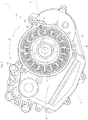
Figure 1 is an external view of a driving unit according to one embodiment of this invention. -
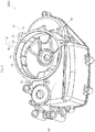
Figure 2 is a plan view of a principal part of the driving unit. -
Figure 3 is a sectional view along the line A-A inFigure 1 . -
Figure 4 is a perspective view of a principal part of a housing. -
Figure 5 is a perspective view of a principal part of a stator. -
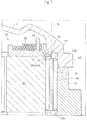
Figure 6 and7 are enlarged sectional views each illustrating a stator fixation structure. -
Figure 8 is an exploded perspective view of a principal part of the driving unit. -
Figure 9 is an external perspective view of a spring pin. -
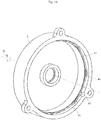
Figure 10 is a perspective view of a rear face of a cover. -
Figure 11 is a perspective view of a bent wire rod. -
Figure 12 is a view of the bent wire rod, whereinFigure 12A illustrates a partial side view of the bent wire rod seen from a direction orthogonal to an axis, and whereinFigure 12B illustrates a plan view of the bent wire rod seen along the axis. -
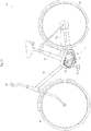
Figure 13 is a left side view of a bicycle having the driving unit mounted thereon. - A description will be given hereinafter of embodiments of this invention with reference to drawings. A driving unit applicable to a bicycle is used for the description as one example of the embodiments.
Figure 1 is an external view of a driving unit according to one embodiment of this invention. - A driving
unit 1 includes ahousing 3 and acover 5. Thecover 5 is fastened to thehousing 3 viabolts 7. Acrankshaft 71 of a bicycle passes through the drivingunit 1. -
Figure 2 is a plan view of a principal part of thedriving unit 1. InFigure 2 , besides thecover 5 and thecrankshaft 71 mentioned above, a rotor or the like is not shown. As illustrated, thehousing 3 includes atubular section 11 of substantially cylindrical shape. Thetubular section 11 accommodates astator 13. Aspring pin 15 is pressed into a gap between thetubular section 11 and thestator 13. - Reference is made to
Figure 3. Figure 3 is a sectional view along the line A-A inFigure 1 . As illustrated, arotor 16 is disposed inside of thestator 13. Therotor 16 is connected to arotary shaft 17 so as to rotate integrally therewith. Therotary shaft 17 is rotatably supported in thehousing 3. Thestator 13, therotor 16, and therotary shaft 17 constitute amotor 18 for generating power. Therotary shaft 17 is interlocked to anoutput shaft 20 via agear unit 19 or the like. Theoutput shaft 20 outputs power generated by themotor 18. - The
cover 5 mentioned above closes an upper opening of thetubular section 11. Thecover 5 contacts anupper end surface 27 of thetubular section 11. Abent wire rod 51 is arranged between thecover 5 and thestator 13 while being compressingly deformed. - The
housing 3 includes aleft case 3L and aright case 3R. The left and right cases are separable from each other. In the following, the description is made simply with respect to thehousing 3 unless a difference needs to be made between theleft case 3L and theright case 3R. - A description will be given hereinafter of each element. In the embodiment of this invention, the term "axis R" is used throughout the specification assuming that the axis R of the
stator 13 substantially conforms to the central axis of thetubular section 11 for convenience. In addition, in the embodiment of this invention, a direction along the axis of thestator 13 from thestator 13 toward thecover 5 is referred to as an "upward direction along the axis R" or "upward" for convenience. In addition, a direction opposite to the direction from thestator 13 toward thecover 5 is referred to as a "downward direction along the axis R" or "downward. For instance, an upper side of the plane ofFigure 3 is referred to as an "upside direction along the axis R" or simply as "upside", whereas a lower side of the plane of the drawing as a "downside direction along the axis R" or simply as "downside". It is noted that this is not a limitation of a direction of the axis R to a specific direction such as a vertical direction. Thestator 13 may be disposed in any directions and attitudes, and accordingly the axis R may extend in any directions. A direction around the axis R is referred to as a "peripheral direction Q". -
Figure 4 is a perspective view of a principal part of thehousing 3. InFigure 4 , only theleft case 3L is illustrated and theright case 3R is omitted. - As illustrated, the
tubular section 11 includes inside thereof aninner wall 21. Theinner wall 21 has an internal diameter slightly larger than an external diameter of thestator 13, allowing accommodating thestator 13. Theinner wall 21 includes a singlefirst groove 23 formed thereon. InFigure 4 , thefirst groove 23 is disposed at a position slightly different from that inFigure 2 . - On lower ends of the
inner wall 21 and thefirst groove 23, aflange 24 is provided which projects inwardly and radially relative to the axis R (hereinafter is abbreviated to "radially" where appropriate). Theflange 24 has an internal diameter smaller than an external diameter of thestator 13. Theflange 24 contacts thestator 13 at a top face thereof to support thestator 13. - The
tubular section 11 further includes a plurality of (e.g., three)bosses 25 for connecting thecover 5. Thehousing 3 further includes aplate section 29 projecting externally from the outer wall of thetubular section 11. Theplate section 29 serves as a wall forming acrankshaft chamber 72 into which thecrankshaft 71 is inserted. - As illustrated in
Figure 3 , thestator 13 includes astator core 31, aninsulated bobbin 35, and acoil 37. Theinsulated bobbin 35 covers thestator core 31. Thecoil 37 is composed of a winding wound around thestator core 31 over theinsulated bobbin 35. -
Figure 5 is a perspective view of a principal part of the stator. As illustrated, asecond groove 33 is formed on anouter wall 32 of thestator core 31, thesecond groove 33 being substantially parallel to the axis R. Thesecond groove 33 has substantially semicircle shape. Thestator core 31 further includes a plurality ofteeth 34. A slot F is formed betweenadjacent teeth 34. Thesecond groove 33 is disposed radially outside of the slot F. -
Figures 6 and7 are each enlarged sectional views of the stator fixation structure. As illustrated, theinsulated bobbin 35 includes acollar 36 extending radially and outwardly to cover the top face of thestator core 31. Thecollar 36 has a diameter slightly smaller than the external diameter of thestator core 31. Accordingly, aperipheral edge 38a of thetop face 38 of thestator core 31 is exposed. -
Figure 8 is an exploded perspective view of a principal part of thedriving unit 1. As illustrated, thestator 13 is attached to thetubular section 11 such that thesecond groove 33 faces thefirst groove 23. This achieves the formation of a substantially circular gap by thefirst groove 23 and thesecond groove 33. -
Figure 9 is an external perspective view of thespring pin 15. As illustrated, thespring pin 15 has substantially cylindrical shape, and includes a slit D parallel to a shaft axis S. Anupper end 15a and alower end 15b of thespring pin 15 are chamfered. The ends are each tapered. When thespring pin 15 is compressingly deformed radially and inwardly relative to the shaft axis S, thespring pin 15 exerts a elastic force radially and outwardly relative to the shaft axis S. - As illustrated in
Figure 7 , thespring pin 15 is pressed into the gap formed by thefirst groove 23 and thesecond groove 33. - As illustrated in
Figure 2 , thespring pin 15 pressed into the gap is kept compressingly deformed, thereby exerting an elastic force. The elastic force causes thespring pin 15 to press a part of the stator 13 (stator core 31) and to press the opposite part of thestator 13 against theinner wall 21 of thetubular section 11. Specifically, assuming that a direction from the shaft axis S of thespring pin 15 toward the axis R is a radial direction V and an intersecting point of the radial direction V and theinner wall 21 is a point C, thestator 13 comes into surface contact with theinner wall 21 within an area extending around the point C along the peripheral direction Q of the axis R. - The
inner wall 21 being in surface contact with thestator 13 receives a load directed radially and outwardly relative to the axis R. This causes a friction force between thestator 13 and theinner wall 21. The friction force allows holding thestator 13. That is, shifting of thestator 13 along the axis R may be suppressed suitably. - Reference is made to
Figures 6 ,7 , and10. Figure 10 is a perspective view of the rear face of thecover 5. The rear face of thecover 5 includes aside wall 41 formed thereon. Theside wall 41 is formed in the peripheral direction Q of the axis R. Theside wall 41 has an internal diameter slightly larger than the external diameter of thestator 13. The stator 13 (stator core 31) projecting from thetubular section 11 is accommodated inside theside wall 41. As noted above, the upper side of thestator 13 is partially accommodated in thecover 5, facilitating a reduction in size of thedriving unit 1. - The
side wall 41 includes anotch 43 formed thereon. The notch is disposed on an extended position of thefirst groove 23. As illustrated inFigure 7 , thespring pin 15 is accommodated in thenotch 43, thespring pin 15 projecting upward from theupper end surface 27 of thetubular section 11. Thespring pin 15 has a length smaller than the dimension of thestator 13 along the axis R. Consequently, thespring pin 15 does not project upward over the stator 13 (stator core 31). - The
cover 5 also includes aprotrusion 45. Theprotrusion 45 projects radially and inwardly from an upper end of theside wall 41. Theprotrusion 45 is inclined downwardly along the axis R radially and inwardly. As a result, an annular recess (space) H is formed between theside wall 41 and theprotrusion 45. - Reference is now made to
Figure 11. Figure 11 is a perspective view of thebent wire rod 51.Figure 12A is a partial side view of thebent wire rod 51 seen from a direction orthogonal to the axis R, andFigure 12B is a plan view of thebent wire rod 51 seen along the axis R.Figure 11 illustrates abent wire rod 51 not compressingly deformed, whereasFigure 12 illustrates abent wire rod 51 compressingly deformed between thecover 5 and thestator 13. - The
bent wire rod 51 is composed of a single wire rod. The wire rod preferably has a cross-section of circular or substantially circular shape. The wire rod is preferably made of a metal such as stainless steel. Examples of the wire rod include round steel, a round wire rod, a steel wire, and a round bar. Thebent wire rod 51 is shaped by bending the wire rod as mentioned above. Consequently, thebent wire rod 51 is composed of a portion of bending the wire rod and/or a portion of extending the wire rod linearly. - Reference is made to
Figure 12A . Thebent wire rod 51 includesprojections 53a anddepressions 53b arranged alternately and successively, theprojections 53a being bent to project upward along the axis R and thedepressions 53b being bent to project downward along the axis R. Consequently, when seen in the peripheral direction Q around the axis R, thebent wire rod 51 has a zigzag or a wavy shape. Theprojections 53a anddepressions 53b are preferably arranged at substantially regular intervals. - Reference is made to
Figure 12B . Theprojections 53a and thedepressions 53b are also bent such that thebent wire rod 51 has a substantially polygonal outer shape with theprojections 53a and thedepressions 53b as vertices when seen along the axis R.Figures 11 and12B clearly illustrate theprojections 53a surrounded by circles and thedepressions 53b surrounded by triangles. As a result, theprojection 53a and thedepression 53b according to the embodiment of this invention also correspond to the corner of this invention. - A
straight portion 55 is formed between theadjacent projection 53a anddepression 53b. Thebent wire rod 51 includesends bent wire rod 51 has a substantially polygonal shape having a portion partially opened when seen along the axis R.Figure 12B illustrates thebent wire rod 51 shaped to be equilateral icositetragon when seen along the axis R. With the open portion, the total number of theprojection 53a and thedepression 53b as vertices is twenty-three. - The
bent wire rod 51 having the above shape is compressingly deformable along the axis R. When compressingly deformed along the axis R, thebent wire rod 51 extends along the axis R to exert an elastic force to cause thebent wire rod 51 to return to its original shape. - As noted above, the
bent wire rod 51 has the substantially polygonal outer shape with only all of theprojections 53a anddepressions 53b as vertices, and no portion other than theprojection 53a anddepression 53b forms a vertex. Consequently, thebent wire rod 51 has essentially a uniform shape regardless of an upside-down rotation. Accordingly, a portion projecting in one direction along the axis R may serve as aprojection 53a or adepression 53b. This allows reducing the work loads of assembling thebent wire rod 51. - The
bent wire rod 51 has an opened portion at theends bent wire rod 51 generates an elastic force causing thebent wire rod 51 to expand radially and outwardly to cause thebent wire rod 51 to return to its original shape. - The
bent wire rod 51 is formed in advance to be a polygon having a larger dimension than the external diameter of thestator 13 when seen along the axis R. This allows thebent wire rod 51 to contact theperipheral edge 38a of thestator 13. In the embodiment of this invention, thebent wire rod 51 is formed in advance to be a polygon having a dimension larger than the internal diameter of theside wall 41. - The
stator 13 is fixed by thebent wire rod 51 as mentioned below. Specifically, as illustrated inFigure 10 , thebent wire rod 51 is disposed along theside wall 41 of thecover 5 while being compressed to have a smaller outer shape. This causes thebent wire rod 51 to generate a radially outward elastic force by which thebent wire rod 51 expands across the entire periphery of theside wall 41. Thebent wire rod 51 itself rests on theside wall 41 so as not to disconnect from thecover 5 under its own weight. - The
cover 5 on which thebent wire rod 51 rests is fastened to thehousing 3. Consequently, as illustrated inFigures 6 and7 , the bent wire rod 51 (thedepressions 53b) contacts theperipheral edge 38a of thestator core 31. The bent wire rod 51 (theprojections 53a) contacts theprotrusion 45 along theside wall 41. Thebent wire rod 51 is compressingly deformable along the axis R. The compressingly deformedbent wire rod 51 exerts an elastic force along the axis R. Theprotrusion 45 receives an elastic force upward along the axis R generated by thebent wire rod 51. Thestator 13 receives an elastic force downward along the axis R generated by thebent wire rod 51. More specifically, thestator core 31 receives an elastic force distributed by all of thedepressions 53b. As a result, the lower surface of thestator core 31 is pressed against theflange 24 of thetubular section 11, resulting in a suppression of a shifting of thestator 13 along the axis R. - As noted above, the
stator 13 is fixed by merely attaching thebent wire rod 51 to thecover 5 and coupling thecover 5 to thehousing 3. Coupling thecover 5 to thehousing 3 allows thebent wire rod 51 to be compressingly deformed at one stroke in a given position to fix thestator 13 to thehousing 3. This achieves fixation of thestator 13 in a shorter period of time with high efficiency. - Moreover, the
bent wire rod 51 is elasticity deformable. Consequently, a variation in the dimension of thestator 13 or thecover 5 along the axis R may be absorbed to press thestator 13 against thetubular section 11 suitably. - Fixing the
stator 13 by the combination of thespring pin 15 mentioned above and thebent wire rod 51, the drivingunit 1 according to the embodiment of this invention further allows to suppress shifting of thestator 13 along the axis R. - Both the
ends bent wire rod 51 are designed not to project beyond theprojections 53a and thedepressions 53b along the axis R when thebent wire rod 51 is compressingly deformed along the axis R as noted above. Specifically, as illustrated inFigure 12A , assuming that an area between theprojections 53a and thedepressions 53b along the axis R is an area G, theends end 57a to theprojection 53a or thedepression 53b nearest to theend 57a is shorter than the length of astraight portion 55 between aprojection 53a and adepression 53b being adjacent. It is more preferable that the distance is one third the length of thestraight portion 55. - Thus, the
bent wire rod 51 prevents theends top face 38 of thestator core 31 and theprotrusion 45 of thecover 5. Consequently, this allows suppressing variations in the elastic force of thebent wire rod 51 along the axis R. - In addition, the
ends bent wire rod 51 fail to contact each other when thebent wire rod 51 is compressingly deformed radially as mentioned above. Consequently, the elastic force of thebent wire rod 51 can be prevented from varying along the axis R and/or radially. If the ends 57a and 57b contact each other, a property of thebent wire rod 51 as an elastic body (a relationship between load and an elastic force) varies. - Moreover, the
protrusion 45 is inclined downwardly along the axis R radially and inwardly. Consequently, thebent wire rod 51 is not able to move radially and inwardly unless thebent wire rod 51 itself is further contracted. Thus, theprotrusion 45 allows suppressing radial shifting of the contact position of thebent wire rod 51 and thecover 5 suitably. In other words, radial and inward shifting of theprojection 53a of thebent wire rod 51 may be suppressed suitably. - Moreover, the
collar 36 of theinsulated bobbin 35 has a dimension slightly smaller than the external diameter of thestator core 31, and thus thetop face 38 of the stator core 31 (peripheral edge 38a) is exposed. This causes thebent wire rod 51 to directly contact thetop face 38 of thestator core 31 having relatively high rigidity. Consequently, thebent wire rod 51 allows the elastic force to act on thestator 13 accurately, allowing thestator 13 to receive the elastic force stably. - As clearly illustrated in
Figure 6 , thecollar 36 extends adjacent to the outerperipheral edge 39 of thestator core 31. Accordingly, thecollar 36 allows suppressing a radial shifting of the contact position of thebent wire rod 51 to thestator 13 suitably. In other words, thecollar 36 allows suppressing the shifting of thedepressions 53b of thebent wire rod 51 suitably. In addition, thecollar 36 is integrated with theinsulated bobbin 35, achieving a simplification of the structure. - Moreover, the
bent wire rod 51 is composed of a wire rod, and, thus, may be disposed suitably within a narrow and annular area, such as theperipheral edge 38a of thestator 13. Accordingly, a reduction in size of thestator 13 and thecover 5 may be achieved. In addition, thebent wire rod 51 may be formed by bending the wire rod, and thus no mold such as press dies is required, resulting in low costs for the production. - The
bent wire rod 51 has an outer shape of a polygon having many vertices seen along the axis R. Accordingly, thebent wire rod 51 may extend suitably along the circumferential surface formed by theside wall 41. Moreover,many depressions 53b of thebent wire rod 51 lead to a decreased pressure of onedepression 53b against thestator 13. In addition, the elastic force may be distributed to act to thestator 13. - Moreover, the
spring pin 15 does not project over thestator 13, thereby suppressing an interference between thespring pin 15 and thebent wire rod 51. - Moreover, the
side wall 41 has the internal diameter slightly larger than the external diameter of thestator 13, and, thus, the stator 13 (stator core 31) projecting from thetubular section 11 may be accommodated inside theside wall 41. As noted above, the upper portion of thestator 13 is partially accommodated in thecover 5, facilitating a reduction in size of thedriving unit 1. - Next, a description of an exemplary application of the
driving unit 1 according to the embodiment of this invention to a bicycle will be given.Figure 13 is a left side view of abicycle 61 with the drivingunit 1 mounted thereon. Thebicycle 61 includes abody frame 63, afront wheel 65 and arear wheel 67 rotatably supported on thebody frame 63, and ahandle 69 supported on thebody frame 63 and steering thefront wheel 65. - The driving
unit 1 is supported on thebody frame 63 around the lower middle portion of thebicycle 61. The drivingunit 1 is provided such that the axis R is substantially horizontal. The drivingunit 1 includes acrankshaft 71 passing therethrough substantially horizontally. Thecrankshaft 71 haspedals 73 coupled thereto on both ends thereof. Pressure on thepedals 73 causes thecrankshaft 71 to rotate. The rotary power of thecrankshaft 71 is transmitted to therear wheel 67 via achain 75. In addition, thebody frame 63 includes abattery 77 supported thereon. Thebattery 77 drives themotor 18 composed of thestator 13 and the like. - Reference is now made to
Figure 3 . Thecrankshaft 71 is inserted into thecrankshaft chamber 72 of thedriving unit 1. Thecrankshaft chamber 72 also includes a torque sensor (not shown) that detects a torque of thecrankshaft 71, and a controller (not shown) that controls themotor 18. Power from themotor 18 is output to anoutput shaft 20. The rotary power from theoutput shaft 20 may be transmitted to therear wheel 67 via thechain 75 mentioned above. - The controller controls the
motor 18 in accordance with detection results from the torque sensor. Themotor 18 generates auxiliary power in accordance with the pressure on thepedals 73. The pressure and the power from themotor 18 are transmitted to thechain 75 via thecrankshaft 71 and theoutput shaft 20, respectively. Thechain 75 combines the pressure and the power to transmit the combined pressure and power to therear wheel 67. This causes thebicycle 61 to move. - In the
bicycle 61, thepedals 73, sometimes, may contact the ground. Thepedals 73 are coupled to thecrankshaft 71. Accordingly, in general, the surface of the driving unit (the outer surface of the housing) of thebicycle 61 may undergo a direct shock, or the interior of the driving unit (crank chamber) may undergo a direct shock through the crankshaft. When the shock is directly transmitted to the inside of the driving unit, a stronger force is transmitted to the stator along the axis R. On the other hand, in thedriving unit 1 according to the embodiment of this invention, the fixation structure mentioned above of thestator 13 is used, and this allows suitably suppressing the shifting of thestator 13 along the axis R. Consequently, the drivingunit 1 according to the embodiment of this invention is suitable for the application to thebicycle 61. - This invention is not limited to the above embodiments, but may be modified as follows.
- (1) The embodiment mentioned above uses both fixation of the
stator 13 by thebent wire rod 51 and that of thestator 13 by thespring pin 15. However, the invention is not limited to such an embodiment. Specifically, in accordance with an embodiment thespring pin 15 may be omitted. - (2) In the embodiment mentioned above, the shape of the
bent wire rod 51 seen along the axis R is an equilateral icositetragon as one example, but the invention is not limited to this. That is, the number of vertices of the polygon may be selected and varied as appropriate. For instance, the polygon may be duodecagonal or more. In addition, the shape is not limited to be an equilateral polygon, but may be a polygon other than this. Alternatively, the shape may be a circle, an ellipse or the like. - (3) In the embodiment mentioned above, the
bent wire rod 51 has a substantially polygonal shape when seen along the axis R with theprojections 53a and thedepressions 53b only as vertices. However, the invention is not limited to such an embodiment. For instance, assuming that a portion corresponding to the vertex of the polygon is a corner, the corner may be provided in addition to theprojections 53a and thedepressions 53b. In other words, the corners may be disposed at a position different from positions of theprojections 53a and thedepressions 53b. Alternatively, theprojections 53a and the depressions 53 may partially serve as the corner. In this case, a corner may also be provided in addition to theprojections 53a and the depressions 53. - In addition, one of the
projection 53a anddepression 53b may serve as a corner, and the other does not serve as a corner. For instance, each of the corners may be formed together with theprojection 53a and not with thedepression 53b. In this case, when seen thebent wire rod 51 along the axis R, thedepression 53b is disposed between the adjacent vertices (corners) of a substantial polygon (i.e., around the center of each side of the polygon). - (4) In the embodiment mentioned above, the
bent wire rod 51 allows generating an elastic force radially and outwardly. However, the invention is not limited to such an embodiment. Specifically, the bent wire rod may be modified as appropriate to generate no elastic force radially and outwardly. - (5) In the embodiment mentioned above, the
bent wire rod 51 is composed of a wire rod having a circular cross-section, but is not limited to this. For instance, the bent wire rod may be modified to be composed of a wire rod having a rectangular cross-section. - (6) In the embodiment mentioned above, the
bent wire rod 51 rests on the cover 5 (side wall 41), but is not limited to this embodiment. For instance, thebent wire rod 51 may rest on thetubular section 11. Alternatively, thebent wire rod 51 may rest on thestator 13. - (7) In the embodiment mentioned above, the contact position of the
bent wire rod 51 and thestator 13 is at theperipheral edge 38a of thestator core 31. However, the invention is not limited to such an embodiment. The contact position may be another position of thestator core 31. In addition, thebent wire rod 51 may contact an element of thestator 13 other than the stator core 31 (e.g., theinsulated bobbin 35 or the coil 37). - (8) In the embodiment mentioned above, the
protrusion 45 is inclined, but is not limited to this embodiment. Specifically, theprotrusion 45 may project in a horizontal direction radially and inwardly relative to the axis R. - (9) In the embodiment mentioned above, the
collar 36 restricting radial and inward shifting of thebent wire rod 51 is integrated with theinsulated bobbin 35. However, the invention is not limited to such an embodiment. Specifically, a restricting element restricting radial and inward shifting of thebent wire rod 51 may be provided in addition to theinsulated bobbin 35. - (10) The embodiment mentioned above has described the
driving unit 1 applicable to the bicycle, but is not limited to this embodiment. Alternatively, the drivingunit 1 may be applied to any other device.
Thecrankshaft chamber 72 may be omitted in such an embodiment. - (11) In the embodiment mentioned above, the
stator 13 has been described as one example of an element of themotor 18, but is not limited to this embodiment. For instance, in an embodiment of this invention thestator 13 constitutes part of a generator. - (12) The embodiment and modifications (1) to (11) mentioned above may be modified as appropriate. For instance, each construction may be modified as appropriate by replacing or combining it with other construction of the modifications.
-
- 1
- driving unit
- 3
- housing
- 5
- cover
- 11
- tubular section
- 13
- stator
- 15
- spring pin
- 16
- rotor
- 18
- motor
- 24
- flange
- 31
- stator core
- 32
- outer wall
- 35
- insulated bobbin
- 36
- collar
- 37
- coil
- 38
- top face
- 38a
- peripheral edge
- 39
- outer peripheral edge
- 41
- side wall
- 45
- protrusion
- 51
- bent wire rod
- 53a
- projection (serving as a corner)
- 53b
- depression (serving as a corner)
- 55
- straight portion
- 57a, 57b
- end
- 61
- bicycle
- 71
- crankshaft
- 72
- crankshaft chamber
- 73
- pedal
- G
- area
- H
- recess (space)
- Q
- peripheral direction
- R
- axis of a stator
- S
- shaft axis of a spring pin
- V
- direction from a shaft axis of a spring pin toward an axis of a stator
- In the following, additional embodiments and aspects of the invention will be described which can be used individually or in combination with any of the features and functionalities and details described herein.
- According to a first aspect, a stator fixation structure may have: a stator; a housing including a tubular section, the stator being accommodated in the tubular section; a cover coupled to the housing for blocking an upper opening of the tubular section; and a bent wire rod composed of a wire for pressing the stator against the tubular section, the bent wire rod being arranged between a top face of the stator and a rear face of the cover in a compressed state so as to be deformed along an axis of the stator, the bent wire rod having a substantially annular shape with an opened portion when seen along the axis, and including projections projecting upward along the axis and depressions projecting downward along the axis, the projections and depressions being arranged alternately and successively, the bent wire rod being arranged such that the projections are in contact with the rear face of the cover and the depressions are in contact with the top face of the stator.
- According to a second aspect with reference to the first aspect, the bent wire rod includes a plurality of corners and a plurality of straight portions so as to be substantially polygonal when seen along the axis, the straight portion connecting the adjacent corners with each other.
- According to a third aspect with reference to the second aspect, the corners are formed at the projections or the depressions.
- According to a fourth aspect with reference to the first aspect, the projections and the depressions are bent such that the outer shape of the bent wire rod is of substantially polygonal shape with the projections and the depressions as vertices when seen along the axis, and the bent wire rod includes straight portions each connecting the adjacent projection and depression.
- According to a fifth aspect with reference to any one of the first to fourth aspects, the bent wire rod, when not being assembled, has a dimension larger than the external diameter of the stator when seen along the axis, and, when being assembled, being deformed so as to have a dimension smaller than the external diameter of the stator.
- According to a sixth aspect with reference to any one of the first to fifth aspects, the bent wire rod is composed of a wire rod having a circular cross-section.
- According to a seventh aspect with reference to any one of the first to sixth aspects, the cover includes a side wall formed on a rear face of the cover in a peripheral direction around the axis, and being in contact with the bent wire rod to receive an elastic force radially and outwardly relative to the axis that is generated by the bent wire rod, and a protrusion projecting from the side wall radially and inwardly relative to the axis to contact the projections and receive an upward elastic force along the axis that is generated by the bent wire rod.
- According to an eighth aspect with reference to the seventh aspect, the side wall has an internal diameter slightly larger than an external diameter of the stator.
- According to a ninth aspect with reference to the seventh or eighth aspect, the protrusion is inclined downwardly along the axis radially and inwardly, and a recess in which the projections are held is provided between the protrusion and the side wall.
- According to a tenth aspect with reference to any one of the first to ninth aspects, the stator includes a stator core and a coil wound around the stator core, and the bent wire rod contacts a top face of the stator core directly.
- According to an eleventh aspect with reference to the tenth aspect, the stator further includes a restricting element disposed on the top face of the stator core and inside from an outer peripheral edge of the stator core for restricting shifting of the bent wire rod radially and inwardly.
- According to a twelfth aspect with reference to the tenth or eleventh aspect, the stator further includes an insulated bobbin disposed between the stator core and the coil for covering the stator core, and the restricting element is integrated with the insulated bobbin.
- According to a thirteenth aspect, a driving unit may have: a motor configured to generate power, the motor including a rotor and a stator outside of the rotor; a housing including a tubular section, the motor accommodated in the tubular section; a cover coupled to the housing for blocking an upper opening of the tubular section; and a bent wire rod composed of a wire rod, the bent wire rod being disposed between a top face of the stator and a rear face of the cover in a compressed state so as to be deformed along an axis of the stator to press the stator against the tubular section, the bent wire rod being substantially annular including an opened portion when seen along the axis, and including projections projecting upward along the axis and depressions projecting downward along the axis, the projections and depressions being arranged alternately and successively, the bent wire rod being arranged such that the projections are in contact with the rear face of the cover, and the depressions are in contact with the top face of the stator.
- According to a fourteenth aspect with reference to the thirteenth aspect, the driving unit is mountable on a bicycle, the housing further includes a crankshaft chamber into which a crankshaft of the bicycle is inserted, and the motor generates power for assisting a pressure on pedals coupled to the crankshaft.
Claims (5)
- A stator structure, comprising:a stator (13);a housing (3) including a tubular section (11), the stator (13) being accommodated in the tubular section (11);a cover (5) coupled to the housing (3) for blocking an upper opening of the tubular section (11); anda bent wire rod (51) composed of a wire for pressing the stator (13) against the tubular section (11), the bent wire rod (51) being in contact with a top face (38) of the stator (13) and a rear face of the cover (5) in a compressed state so as to be deformed along an axis (R) substantially conforming to the central axis of the tubular section (11),the bent wire rod (51) having a substantially annular shape with an opened portion when seen along the axis (R), and including projections (53a) projecting upward along the axis (R) and depressions (53b) projecting downward along the axis (R), the projections (53a) and depressions (53b) being arranged alternately and successively, the bent wire rod (51) being arranged such that the projections (53a) are in contact with the rear face of the cover (5) and the depressions (53b) are in contact with the top face (38) of the stator (13),the stator (13) includes a stator core (31) and a coil (37) wound around the stator core (31),the bent wire rod (51) contacts a top face (38) of the stator core (31) directly, andthe stator (13) further includes a restricting element (36) disposed on the top face (38) of the stator core (31) and inside from an outer peripheral edge of the stator core (31) for restricting shifting of the bent wire rod (51) radially and inwardly.
- The stator structure according to claim 1, wherein
the stator (13) further includes an insulated bobbin (35) disposed between the stator core (31) and the coil (37) for covering the stator core (31), and
the restricting element (36) is integrated with the insulated bobbin (35). - A driving unit, comprising:a motor (18) configured to generate power, the motor (18) including a rotor (16) and a stator (13) outside of the rotor (16); anda stator structure according to any of claims 1 to 2.
- The driving unit according to claim 3, wherein
the driving unit is mountable on a bicycle (61),
the housing (3) further includes a crankshaft chamber (72) into which a crankshaft (71) of the bicycle (61) is inserted, and
the motor (18) is configured to generate power for assisting a pressure on pedals (73) coupled to the crankshaft (71). - A bicycle (61) comprising a body frame (63), a front wheel (65) and a rear wheel (67) rotatably supported on the body frame (63), and a handle (69) supported on the body frame (63) and configured for steering the front wheel (65), the bicycle (61) further comprising the driving unit according to claim 3 or 4.
Applications Claiming Priority (3)
| Application Number | Priority Date | Filing Date | Title |
|---|---|---|---|
| JP2011051685A JP5603810B2 (en) | 2011-03-09 | 2011-03-09 | Stator fixing structure and drive device |
| PCT/JP2012/001154 WO2012120801A1 (en) | 2011-03-09 | 2012-02-21 | Stator anchoring structure and drive device |
| EP12755553.0A EP2685604B1 (en) | 2011-03-09 | 2012-02-21 | Stator anchoring structure and drive device |
Related Parent Applications (2)
| Application Number | Title | Priority Date | Filing Date |
|---|---|---|---|
| EP12755553.0A Division EP2685604B1 (en) | 2011-03-09 | 2012-02-21 | Stator anchoring structure and drive device |
| EP12755553.0A Division-Into EP2685604B1 (en) | 2011-03-09 | 2012-02-21 | Stator anchoring structure and drive device |
Publications (2)
| Publication Number | Publication Date |
|---|---|
| EP3605795A1 true EP3605795A1 (en) | 2020-02-05 |
| EP3605795B1 EP3605795B1 (en) | 2020-11-11 |
Family
ID=46797777
Family Applications (2)
| Application Number | Title | Priority Date | Filing Date |
|---|---|---|---|
| EP12755553.0A Active EP2685604B1 (en) | 2011-03-09 | 2012-02-21 | Stator anchoring structure and drive device |
| EP19197988.9A Active EP3605795B1 (en) | 2011-03-09 | 2012-02-21 | Stator fixation structure and driving unit |
Family Applications Before (1)
| Application Number | Title | Priority Date | Filing Date |
|---|---|---|---|
| EP12755553.0A Active EP2685604B1 (en) | 2011-03-09 | 2012-02-21 | Stator anchoring structure and drive device |
Country Status (6)
| Country | Link |
|---|---|
| US (2) | US9236774B2 (en) |
| EP (2) | EP2685604B1 (en) |
| JP (1) | JP5603810B2 (en) |
| CN (2) | CN103415980B (en) |
| TW (2) | TWI488411B (en) |
| WO (1) | WO2012120801A1 (en) |
Families Citing this family (9)
| Publication number | Priority date | Publication date | Assignee | Title |
|---|---|---|---|---|
| JP5603810B2 (en) * | 2011-03-09 | 2014-10-08 | ヤマハモーターエレクトロニクス株式会社 | Stator fixing structure and drive device |
| JP6370736B2 (en) | 2015-03-31 | 2018-08-08 | 株式会社シマノ | Bicycle drive unit and bicycle equipped with this drive unit |
| JP6514995B2 (en) * | 2015-08-31 | 2019-05-15 | 株式会社シマノ | Bicycle guard and drive unit having the same |
| JP6721403B2 (en) * | 2016-04-28 | 2020-07-15 | ヤマハ発動機株式会社 | Electric assisted bicycle |
| USD936105S1 (en) * | 2018-06-15 | 2021-11-16 | Fukuta Electric & Machinery Co., Ltd. | Motor assembly for an electric scooter |
| USD936106S1 (en) * | 2019-03-12 | 2021-11-16 | Fukuta Electric & Machinery Co., Ltd. | Motor assembly for an electric scooter |
| DE102019215563A1 (en) * | 2019-10-10 | 2021-04-15 | Zf Friedrichshafen Ag | Stator of an electrical machine |
| FR3103653A1 (en) * | 2019-11-22 | 2021-05-28 | Valeo Equipements Electriques Moteur | Rotating electric machine with axial stator locking |
| JP1684126S (en) * | 2020-09-30 | 2021-04-26 |
Citations (5)
| Publication number | Priority date | Publication date | Assignee | Title |
|---|---|---|---|---|
| JPH0670523A (en) | 1992-08-19 | 1994-03-11 | Matsushita Electric Ind Co Ltd | Brushless motor |
| US5315200A (en) * | 1992-07-16 | 1994-05-24 | Ford Motor Company | Electrical motor stator installation |
| JP2008271747A (en) * | 2007-04-24 | 2008-11-06 | Asmo Co Ltd | Rotary electric machine and washer member |
| US20090121570A1 (en) * | 2007-11-12 | 2009-05-14 | Mitsubishi Electric Corporation | Motor for an electric power steering apparatus |
| JP2010178469A (en) * | 2009-01-28 | 2010-08-12 | Calsonic Kansei Corp | Motor |
Family Cites Families (13)
| Publication number | Priority date | Publication date | Assignee | Title |
|---|---|---|---|---|
| US2154146A (en) * | 1935-09-02 | 1939-04-11 | John Edward Becker | Electric motor, dynamo, and the like |
| JPS57186937A (en) | 1982-04-28 | 1982-11-17 | Toshiba Corp | Stator for electric rotary machine |
| JPH0326250U (en) * | 1989-07-21 | 1991-03-18 | ||
| JPH05137290A (en) * | 1991-11-12 | 1993-06-01 | Mitsubishi Electric Corp | Ac generator for vehicle |
| JP2001507908A (en) | 1997-11-07 | 2001-06-12 | コーニンクレッカ フィリップス エレクトロニクス エヌ ヴィ | Image sequence encoding |
| US6100615A (en) * | 1998-05-11 | 2000-08-08 | Birkestrand; Orville J. | Modular motorized electric wheel hub assembly for bicycles and the like |
| JP3998118B2 (en) * | 2000-10-10 | 2007-10-24 | 本田技研工業株式会社 | Electric vehicle |
| US7026742B2 (en) * | 2002-04-01 | 2006-04-11 | Nissan Motor Co., Ltd. | Stator mounting for a double rotor electric motor |
| JP2004048925A (en) * | 2002-07-12 | 2004-02-12 | Toyota Motor Corp | Fixing method and fixing structure for stator, and fixing method and fixing structure for rotor |
| JP2005335536A (en) * | 2004-05-27 | 2005-12-08 | Sanyo Electric Co Ltd | Hub unit for electromotive vehicle wheel, and vehicle with the hub unit |
| US20100141059A1 (en) * | 2005-10-24 | 2010-06-10 | Matsushita Electric Industrial Co., Ltd. | Capacitor motor and process for producing the same |
| WO2007141126A1 (en) * | 2006-06-02 | 2007-12-13 | Brose Fahrzeugteile Gmbh & Co. Kg, Würzburg | Electric motor and method for manufacturing an electric motor for a motor vehicle actuator drive |
| JP5603810B2 (en) * | 2011-03-09 | 2014-10-08 | ヤマハモーターエレクトロニクス株式会社 | Stator fixing structure and drive device |
-
2011
- 2011-03-09 JP JP2011051685A patent/JP5603810B2/en active Active
-
2012
- 2012-02-21 CN CN201280012263.3A patent/CN103415980B/en active Active
- 2012-02-21 EP EP12755553.0A patent/EP2685604B1/en active Active
- 2012-02-21 CN CN201610096390.6A patent/CN105553138B/en active Active
- 2012-02-21 US US14/003,291 patent/US9236774B2/en active Active
- 2012-02-21 EP EP19197988.9A patent/EP3605795B1/en active Active
- 2012-02-21 WO PCT/JP2012/001154 patent/WO2012120801A1/en active Application Filing
- 2012-03-07 TW TW103120391A patent/TWI488411B/en active
- 2012-03-07 TW TW101107775A patent/TWI443943B/en active
-
2015
- 2015-12-04 US US14/959,044 patent/US9496763B2/en active Active
Patent Citations (5)
| Publication number | Priority date | Publication date | Assignee | Title |
|---|---|---|---|---|
| US5315200A (en) * | 1992-07-16 | 1994-05-24 | Ford Motor Company | Electrical motor stator installation |
| JPH0670523A (en) | 1992-08-19 | 1994-03-11 | Matsushita Electric Ind Co Ltd | Brushless motor |
| JP2008271747A (en) * | 2007-04-24 | 2008-11-06 | Asmo Co Ltd | Rotary electric machine and washer member |
| US20090121570A1 (en) * | 2007-11-12 | 2009-05-14 | Mitsubishi Electric Corporation | Motor for an electric power steering apparatus |
| JP2010178469A (en) * | 2009-01-28 | 2010-08-12 | Calsonic Kansei Corp | Motor |
Also Published As
| Publication number | Publication date |
|---|---|
| TWI488411B (en) | 2015-06-11 |
| CN103415980B (en) | 2016-03-30 |
| JP5603810B2 (en) | 2014-10-08 |
| CN105553138B (en) | 2018-09-28 |
| US9236774B2 (en) | 2016-01-12 |
| TW201251281A (en) | 2012-12-16 |
| US20160087504A1 (en) | 2016-03-24 |
| CN103415980A (en) | 2013-11-27 |
| CN105553138A (en) | 2016-05-04 |
| EP2685604B1 (en) | 2019-11-27 |
| US20130341112A1 (en) | 2013-12-26 |
| TWI443943B (en) | 2014-07-01 |
| WO2012120801A1 (en) | 2012-09-13 |
| EP2685604A1 (en) | 2014-01-15 |
| JP2012191714A (en) | 2012-10-04 |
| TW201438381A (en) | 2014-10-01 |
| EP3605795B1 (en) | 2020-11-11 |
| EP2685604A4 (en) | 2016-03-09 |
| US9496763B2 (en) | 2016-11-15 |
Similar Documents
| Publication | Publication Date | Title |
|---|---|---|
| EP3605795B1 (en) | Stator fixation structure and driving unit | |
| KR100341775B1 (en) | Rotor structure | |
| CN104659959B (en) | Belt driven type starter-generator | |
| CN105683576B (en) | Electric scroll compressor | |
| EP2075094A1 (en) | Rotary power tool with a gearbox to motor interface that facilitates assembly | |
| JP2009033884A (en) | Stator and manufacturing method of stator | |
| JP5971314B2 (en) | Rotating electric machine for internal combustion engine | |
| US7825556B2 (en) | Stepping motor | |
| JP6744194B2 (en) | Bearing holding structure and motor | |
| EP2456046B1 (en) | Stator, and motor comprising same | |
| EP2685603A1 (en) | Stator anchoring structure and drive device | |
| JP5971315B2 (en) | Rotating electric machine for internal combustion engine | |
| US20190036416A1 (en) | Rotary electric machine | |
| KR20150115464A (en) | Motor | |
| JP2004215441A (en) | Rotary electric machine unit | |
| KR102365919B1 (en) | Motor | |
| JP2005278292A (en) | Fixed structure of stator core | |
| JP6910414B2 (en) | Rotating machine | |
| US20200381966A1 (en) | Motor and electrical product | |
| JP6740464B2 (en) | Outer rotor type rotating electric machine | |
| JP2021018215A (en) | Fastening structure for metal case and resin holder of torque sensor | |
| JP2016052235A (en) | Stator core |
Legal Events
| Date | Code | Title | Description |
|---|---|---|---|
| PUAI | Public reference made under article 153(3) epc to a published international application that has entered the european phase |
Free format text: ORIGINAL CODE: 0009012 |
|
| STAA | Information on the status of an ep patent application or granted ep patent |
Free format text: STATUS: THE APPLICATION HAS BEEN PUBLISHED |
|
| AC | Divisional application: reference to earlier application |
Ref document number: 2685604 Country of ref document: EP Kind code of ref document: P |
|
| AK | Designated contracting states |
Kind code of ref document: A1 Designated state(s): AL AT BE BG CH CY CZ DE DK EE ES FI FR GB GR HR HU IE IS IT LI LT LU LV MC MK MT NL NO PL PT RO RS SE SI SK SM TR |
|
| STAA | Information on the status of an ep patent application or granted ep patent |
Free format text: STATUS: REQUEST FOR EXAMINATION WAS MADE |
|
| 17P | Request for examination filed |
Effective date: 20200226 |
|
| RBV | Designated contracting states (corrected) |
Designated state(s): AL AT BE BG CH CY CZ DE DK EE ES FI FR GB GR HR HU IE IS IT LI LT LU LV MC MK MT NL NO PL PT RO RS SE SI SK SM TR |
|
| GRAP | Despatch of communication of intention to grant a patent |
Free format text: ORIGINAL CODE: EPIDOSNIGR1 |
|
| STAA | Information on the status of an ep patent application or granted ep patent |
Free format text: STATUS: GRANT OF PATENT IS INTENDED |
|
| INTG | Intention to grant announced |
Effective date: 20200604 |
|
| GRAS | Grant fee paid |
Free format text: ORIGINAL CODE: EPIDOSNIGR3 |
|
| GRAA | (expected) grant |
Free format text: ORIGINAL CODE: 0009210 |
|
| STAA | Information on the status of an ep patent application or granted ep patent |
Free format text: STATUS: THE PATENT HAS BEEN GRANTED |
|
| AC | Divisional application: reference to earlier application |
Ref document number: 2685604 Country of ref document: EP Kind code of ref document: P |
|
| AK | Designated contracting states |
Kind code of ref document: B1 Designated state(s): AL AT BE BG CH CY CZ DE DK EE ES FI FR GB GR HR HU IE IS IT LI LT LU LV MC MK MT NL NO PL PT RO RS SE SI SK SM TR |
|
| REG | Reference to a national code |
Ref country code: GB Ref legal event code: FG4D |
|
| REG | Reference to a national code |
Ref country code: CH Ref legal event code: EP |
|
| REG | Reference to a national code |
Ref country code: AT Ref legal event code: REF Ref document number: 1334379 Country of ref document: AT Kind code of ref document: T Effective date: 20201115 |
|
| REG | Reference to a national code |
Ref country code: DE Ref legal event code: R096 Ref document number: 602012073247 Country of ref document: DE |
|
| REG | Reference to a national code |
Ref country code: IE Ref legal event code: FG4D |
|
| REG | Reference to a national code |
Ref country code: NL Ref legal event code: FP |
|
| REG | Reference to a national code |
Ref country code: AT Ref legal event code: MK05 Ref document number: 1334379 Country of ref document: AT Kind code of ref document: T Effective date: 20201111 |
|
| PG25 | Lapsed in a contracting state [announced via postgrant information from national office to epo] |
Ref country code: NO Free format text: LAPSE BECAUSE OF FAILURE TO SUBMIT A TRANSLATION OF THE DESCRIPTION OR TO PAY THE FEE WITHIN THE PRESCRIBED TIME-LIMIT Effective date: 20210211 Ref country code: GR Free format text: LAPSE BECAUSE OF FAILURE TO SUBMIT A TRANSLATION OF THE DESCRIPTION OR TO PAY THE FEE WITHIN THE PRESCRIBED TIME-LIMIT Effective date: 20210212 Ref country code: PT Free format text: LAPSE BECAUSE OF FAILURE TO SUBMIT A TRANSLATION OF THE DESCRIPTION OR TO PAY THE FEE WITHIN THE PRESCRIBED TIME-LIMIT Effective date: 20210311 Ref country code: RS Free format text: LAPSE BECAUSE OF FAILURE TO SUBMIT A TRANSLATION OF THE DESCRIPTION OR TO PAY THE FEE WITHIN THE PRESCRIBED TIME-LIMIT Effective date: 20201111 Ref country code: FI Free format text: LAPSE BECAUSE OF FAILURE TO SUBMIT A TRANSLATION OF THE DESCRIPTION OR TO PAY THE FEE WITHIN THE PRESCRIBED TIME-LIMIT Effective date: 20201111 |
|
| PG25 | Lapsed in a contracting state [announced via postgrant information from national office to epo] |
Ref country code: AT Free format text: LAPSE BECAUSE OF FAILURE TO SUBMIT A TRANSLATION OF THE DESCRIPTION OR TO PAY THE FEE WITHIN THE PRESCRIBED TIME-LIMIT Effective date: 20201111 Ref country code: PL Free format text: LAPSE BECAUSE OF FAILURE TO SUBMIT A TRANSLATION OF THE DESCRIPTION OR TO PAY THE FEE WITHIN THE PRESCRIBED TIME-LIMIT Effective date: 20201111 Ref country code: IS Free format text: LAPSE BECAUSE OF FAILURE TO SUBMIT A TRANSLATION OF THE DESCRIPTION OR TO PAY THE FEE WITHIN THE PRESCRIBED TIME-LIMIT Effective date: 20210311 Ref country code: LV Free format text: LAPSE BECAUSE OF FAILURE TO SUBMIT A TRANSLATION OF THE DESCRIPTION OR TO PAY THE FEE WITHIN THE PRESCRIBED TIME-LIMIT Effective date: 20201111 Ref country code: SE Free format text: LAPSE BECAUSE OF FAILURE TO SUBMIT A TRANSLATION OF THE DESCRIPTION OR TO PAY THE FEE WITHIN THE PRESCRIBED TIME-LIMIT Effective date: 20201111 Ref country code: BG Free format text: LAPSE BECAUSE OF FAILURE TO SUBMIT A TRANSLATION OF THE DESCRIPTION OR TO PAY THE FEE WITHIN THE PRESCRIBED TIME-LIMIT Effective date: 20210211 |
|
| REG | Reference to a national code |
Ref country code: LT Ref legal event code: MG9D |
|
| PG25 | Lapsed in a contracting state [announced via postgrant information from national office to epo] |
Ref country code: HR Free format text: LAPSE BECAUSE OF FAILURE TO SUBMIT A TRANSLATION OF THE DESCRIPTION OR TO PAY THE FEE WITHIN THE PRESCRIBED TIME-LIMIT Effective date: 20201111 |
|
| PG25 | Lapsed in a contracting state [announced via postgrant information from national office to epo] |
Ref country code: CZ Free format text: LAPSE BECAUSE OF FAILURE TO SUBMIT A TRANSLATION OF THE DESCRIPTION OR TO PAY THE FEE WITHIN THE PRESCRIBED TIME-LIMIT Effective date: 20201111 Ref country code: SM Free format text: LAPSE BECAUSE OF FAILURE TO SUBMIT A TRANSLATION OF THE DESCRIPTION OR TO PAY THE FEE WITHIN THE PRESCRIBED TIME-LIMIT Effective date: 20201111 Ref country code: SK Free format text: LAPSE BECAUSE OF FAILURE TO SUBMIT A TRANSLATION OF THE DESCRIPTION OR TO PAY THE FEE WITHIN THE PRESCRIBED TIME-LIMIT Effective date: 20201111 Ref country code: EE Free format text: LAPSE BECAUSE OF FAILURE TO SUBMIT A TRANSLATION OF THE DESCRIPTION OR TO PAY THE FEE WITHIN THE PRESCRIBED TIME-LIMIT Effective date: 20201111 Ref country code: RO Free format text: LAPSE BECAUSE OF FAILURE TO SUBMIT A TRANSLATION OF THE DESCRIPTION OR TO PAY THE FEE WITHIN THE PRESCRIBED TIME-LIMIT Effective date: 20201111 Ref country code: LT Free format text: LAPSE BECAUSE OF FAILURE TO SUBMIT A TRANSLATION OF THE DESCRIPTION OR TO PAY THE FEE WITHIN THE PRESCRIBED TIME-LIMIT Effective date: 20201111 |
|
| REG | Reference to a national code |
Ref country code: DE Ref legal event code: R097 Ref document number: 602012073247 Country of ref document: DE |
|
| PG25 | Lapsed in a contracting state [announced via postgrant information from national office to epo] |
Ref country code: DK Free format text: LAPSE BECAUSE OF FAILURE TO SUBMIT A TRANSLATION OF THE DESCRIPTION OR TO PAY THE FEE WITHIN THE PRESCRIBED TIME-LIMIT Effective date: 20201111 |
|
| PLBE | No opposition filed within time limit |
Free format text: ORIGINAL CODE: 0009261 |
|
| STAA | Information on the status of an ep patent application or granted ep patent |
Free format text: STATUS: NO OPPOSITION FILED WITHIN TIME LIMIT |
|
| PG25 | Lapsed in a contracting state [announced via postgrant information from national office to epo] |
Ref country code: MC Free format text: LAPSE BECAUSE OF FAILURE TO SUBMIT A TRANSLATION OF THE DESCRIPTION OR TO PAY THE FEE WITHIN THE PRESCRIBED TIME-LIMIT Effective date: 20201111 |
|
| 26N | No opposition filed |
Effective date: 20210812 |
|
| GBPC | Gb: european patent ceased through non-payment of renewal fee |
Effective date: 20210221 |
|
| REG | Reference to a national code |
Ref country code: BE Ref legal event code: MM Effective date: 20210228 |
|
| PG25 | Lapsed in a contracting state [announced via postgrant information from national office to epo] |
Ref country code: LI Free format text: LAPSE BECAUSE OF NON-PAYMENT OF DUE FEES Effective date: 20210228 Ref country code: LU Free format text: LAPSE BECAUSE OF NON-PAYMENT OF DUE FEES Effective date: 20210221 Ref country code: IT Free format text: LAPSE BECAUSE OF FAILURE TO SUBMIT A TRANSLATION OF THE DESCRIPTION OR TO PAY THE FEE WITHIN THE PRESCRIBED TIME-LIMIT Effective date: 20201111 Ref country code: CH Free format text: LAPSE BECAUSE OF NON-PAYMENT OF DUE FEES Effective date: 20210228 Ref country code: AL Free format text: LAPSE BECAUSE OF FAILURE TO SUBMIT A TRANSLATION OF THE DESCRIPTION OR TO PAY THE FEE WITHIN THE PRESCRIBED TIME-LIMIT Effective date: 20201111 |
|
| PG25 | Lapsed in a contracting state [announced via postgrant information from national office to epo] |
Ref country code: SI Free format text: LAPSE BECAUSE OF FAILURE TO SUBMIT A TRANSLATION OF THE DESCRIPTION OR TO PAY THE FEE WITHIN THE PRESCRIBED TIME-LIMIT Effective date: 20201111 |
|
| PG25 | Lapsed in a contracting state [announced via postgrant information from national office to epo] |
Ref country code: ES Free format text: LAPSE BECAUSE OF FAILURE TO SUBMIT A TRANSLATION OF THE DESCRIPTION OR TO PAY THE FEE WITHIN THE PRESCRIBED TIME-LIMIT Effective date: 20201111 Ref country code: GB Free format text: LAPSE BECAUSE OF NON-PAYMENT OF DUE FEES Effective date: 20210221 Ref country code: FR Free format text: LAPSE BECAUSE OF NON-PAYMENT OF DUE FEES Effective date: 20210228 Ref country code: IE Free format text: LAPSE BECAUSE OF NON-PAYMENT OF DUE FEES Effective date: 20210221 |
|
| PG25 | Lapsed in a contracting state [announced via postgrant information from national office to epo] |
Ref country code: IS Free format text: LAPSE BECAUSE OF FAILURE TO SUBMIT A TRANSLATION OF THE DESCRIPTION OR TO PAY THE FEE WITHIN THE PRESCRIBED TIME-LIMIT Effective date: 20210311 |
|
| PG25 | Lapsed in a contracting state [announced via postgrant information from national office to epo] |
Ref country code: BE Free format text: LAPSE BECAUSE OF NON-PAYMENT OF DUE FEES Effective date: 20210228 |
|
| PG25 | Lapsed in a contracting state [announced via postgrant information from national office to epo] |
Ref country code: CY Free format text: LAPSE BECAUSE OF FAILURE TO SUBMIT A TRANSLATION OF THE DESCRIPTION OR TO PAY THE FEE WITHIN THE PRESCRIBED TIME-LIMIT Effective date: 20201111 |
|
| P01 | Opt-out of the competence of the unified patent court (upc) registered |
Effective date: 20230527 |
|
| PG25 | Lapsed in a contracting state [announced via postgrant information from national office to epo] |
Ref country code: HU Free format text: LAPSE BECAUSE OF FAILURE TO SUBMIT A TRANSLATION OF THE DESCRIPTION OR TO PAY THE FEE WITHIN THE PRESCRIBED TIME-LIMIT; INVALID AB INITIO Effective date: 20120221 |
|
| PGFP | Annual fee paid to national office [announced via postgrant information from national office to epo] |
Ref country code: NL Payment date: 20240219 Year of fee payment: 13 |
|
| PG25 | Lapsed in a contracting state [announced via postgrant information from national office to epo] |
Ref country code: MK Free format text: LAPSE BECAUSE OF FAILURE TO SUBMIT A TRANSLATION OF THE DESCRIPTION OR TO PAY THE FEE WITHIN THE PRESCRIBED TIME-LIMIT Effective date: 20201111 |
|
| PGFP | Annual fee paid to national office [announced via postgrant information from national office to epo] |
Ref country code: DE Payment date: 20240219 Year of fee payment: 13 |