EP3605765A1 - Identification of faulty section of power transmission line - Google Patents
Identification of faulty section of power transmission line Download PDFInfo
- Publication number
- EP3605765A1 EP3605765A1 EP18195509.7A EP18195509A EP3605765A1 EP 3605765 A1 EP3605765 A1 EP 3605765A1 EP 18195509 A EP18195509 A EP 18195509A EP 3605765 A1 EP3605765 A1 EP 3605765A1
- Authority
- EP
- European Patent Office
- Prior art keywords
- junction
- section
- voltage
- current
- terminal
- Prior art date
- Legal status (The legal status is an assumption and is not a legal conclusion. Google has not performed a legal analysis and makes no representation as to the accuracy of the status listed.)
- Pending
Links
- 230000005540 biological transmission Effects 0.000 title claims abstract description 68
- 238000000034 method Methods 0.000 claims abstract description 38
- 238000005259 measurement Methods 0.000 claims description 8
- PCTMTFRHKVHKIS-BMFZQQSSSA-N (1s,3r,4e,6e,8e,10e,12e,14e,16e,18s,19r,20r,21s,25r,27r,30r,31r,33s,35r,37s,38r)-3-[(2r,3s,4s,5s,6r)-4-amino-3,5-dihydroxy-6-methyloxan-2-yl]oxy-19,25,27,30,31,33,35,37-octahydroxy-18,20,21-trimethyl-23-oxo-22,39-dioxabicyclo[33.3.1]nonatriaconta-4,6,8,10 Chemical compound C1C=C2C[C@@H](OS(O)(=O)=O)CC[C@]2(C)[C@@H]2[C@@H]1[C@@H]1CC[C@H]([C@H](C)CCCC(C)C)[C@@]1(C)CC2.O[C@H]1[C@@H](N)[C@H](O)[C@@H](C)O[C@H]1O[C@H]1/C=C/C=C/C=C/C=C/C=C/C=C/C=C/[C@H](C)[C@@H](O)[C@@H](C)[C@H](C)OC(=O)C[C@H](O)C[C@H](O)CC[C@@H](O)[C@H](O)C[C@H](O)C[C@](O)(C[C@H](O)[C@H]2C(O)=O)O[C@H]2C1 PCTMTFRHKVHKIS-BMFZQQSSSA-N 0.000 description 7
- 238000005070 sampling Methods 0.000 description 4
- 230000001052 transient effect Effects 0.000 description 4
- 238000004891 communication Methods 0.000 description 2
- 230000000903 blocking effect Effects 0.000 description 1
- 239000000835 fiber Substances 0.000 description 1
- 238000012986 modification Methods 0.000 description 1
- 230000004048 modification Effects 0.000 description 1
Images


Classifications
-
- H—ELECTRICITY
- H02—GENERATION; CONVERSION OR DISTRIBUTION OF ELECTRIC POWER
- H02H—EMERGENCY PROTECTIVE CIRCUIT ARRANGEMENTS
- H02H3/00—Emergency protective circuit arrangements for automatic disconnection directly responsive to an undesired change from normal electric working condition with or without subsequent reconnection ; integrated protection
- H02H3/02—Details
- H02H3/04—Details with warning or supervision in addition to disconnection, e.g. for indicating that protective apparatus has functioned
- H02H3/042—Details with warning or supervision in addition to disconnection, e.g. for indicating that protective apparatus has functioned combined with means for locating the fault
-
- G—PHYSICS
- G01—MEASURING; TESTING
- G01R—MEASURING ELECTRIC VARIABLES; MEASURING MAGNETIC VARIABLES
- G01R31/00—Arrangements for testing electric properties; Arrangements for locating electric faults; Arrangements for electrical testing characterised by what is being tested not provided for elsewhere
- G01R31/08—Locating faults in cables, transmission lines, or networks
- G01R31/088—Aspects of digital computing
-
- G—PHYSICS
- G01—MEASURING; TESTING
- G01R—MEASURING ELECTRIC VARIABLES; MEASURING MAGNETIC VARIABLES
- G01R31/00—Arrangements for testing electric properties; Arrangements for locating electric faults; Arrangements for electrical testing characterised by what is being tested not provided for elsewhere
- G01R31/08—Locating faults in cables, transmission lines, or networks
- G01R31/081—Locating faults in cables, transmission lines, or networks according to type of conductors
- G01R31/083—Locating faults in cables, transmission lines, or networks according to type of conductors in cables, e.g. underground
-
- G—PHYSICS
- G01—MEASURING; TESTING
- G01R—MEASURING ELECTRIC VARIABLES; MEASURING MAGNETIC VARIABLES
- G01R31/00—Arrangements for testing electric properties; Arrangements for locating electric faults; Arrangements for electrical testing characterised by what is being tested not provided for elsewhere
- G01R31/08—Locating faults in cables, transmission lines, or networks
- G01R31/081—Locating faults in cables, transmission lines, or networks according to type of conductors
- G01R31/085—Locating faults in cables, transmission lines, or networks according to type of conductors in power transmission or distribution lines, e.g. overhead
-
- H—ELECTRICITY
- H02—GENERATION; CONVERSION OR DISTRIBUTION OF ELECTRIC POWER
- H02H—EMERGENCY PROTECTIVE CIRCUIT ARRANGEMENTS
- H02H1/00—Details of emergency protective circuit arrangements
- H02H1/0007—Details of emergency protective circuit arrangements concerning the detecting means
-
- H—ELECTRICITY
- H02—GENERATION; CONVERSION OR DISTRIBUTION OF ELECTRIC POWER
- H02H—EMERGENCY PROTECTIVE CIRCUIT ARRANGEMENTS
- H02H7/00—Emergency protective circuit arrangements specially adapted for specific types of electric machines or apparatus or for sectionalised protection of cable or line systems, and effecting automatic switching in the event of an undesired change from normal working conditions
- H02H7/26—Sectionalised protection of cable or line systems, e.g. for disconnecting a section on which a short-circuit, earth fault, or arc discharge has occured
- H02H7/261—Sectionalised protection of cable or line systems, e.g. for disconnecting a section on which a short-circuit, earth fault, or arc discharge has occured involving signal transmission between at least two stations
- H02H7/263—Sectionalised protection of cable or line systems, e.g. for disconnecting a section on which a short-circuit, earth fault, or arc discharge has occured involving signal transmission between at least two stations involving transmissions of measured values
-
- Y—GENERAL TAGGING OF NEW TECHNOLOGICAL DEVELOPMENTS; GENERAL TAGGING OF CROSS-SECTIONAL TECHNOLOGIES SPANNING OVER SEVERAL SECTIONS OF THE IPC; TECHNICAL SUBJECTS COVERED BY FORMER USPC CROSS-REFERENCE ART COLLECTIONS [XRACs] AND DIGESTS
- Y04—INFORMATION OR COMMUNICATION TECHNOLOGIES HAVING AN IMPACT ON OTHER TECHNOLOGY AREAS
- Y04S—SYSTEMS INTEGRATING TECHNOLOGIES RELATED TO POWER NETWORK OPERATION, COMMUNICATION OR INFORMATION TECHNOLOGIES FOR IMPROVING THE ELECTRICAL POWER GENERATION, TRANSMISSION, DISTRIBUTION, MANAGEMENT OR USAGE, i.e. SMART GRIDS
- Y04S10/00—Systems supporting electrical power generation, transmission or distribution
- Y04S10/50—Systems or methods supporting the power network operation or management, involving a certain degree of interaction with the load-side end user applications
- Y04S10/52—Outage or fault management, e.g. fault detection or location
Definitions
- the present subject matter relates, in general, to power transmission lines and, in particular, to identification of a section of a power transmission line having a fault.
- Power transmission lines can be used for transmitting electric power from generating stations that generate electric power to consumers of the electric power.
- a power transmission line may include a plurality of sections, such as an overhead line (OHL) section and an underground cable (UGC) section.
- OOL overhead line
- ULC underground cable
- a section of the power transmission line may have a fault, such as a phase-to-ground fault or a phase-to-phase fault.
- the present subject matter relates to systems and methods for identification of a section of a power transmission line that has a fault.
- a power transmission line may include more than one section.
- the power transmission line may include an overhead line (OHL) section and an underground cable (UGC) section joined together at a junction.
- OHL overhead line
- UGC underground cable
- a power transmission line having both an OHL section and a UGC section may be referred to as a mixed power transmission line.
- faults electrical faults, commonly referred to as faults, may occur on the power transmission lines.
- the fault may occur in any section, such as in the OHL section or UGC section.
- a section on which the fault has occurred may have to be determined.
- One reason for performing the determination is to decide whether auto-reclosing of a circuit breaker on the power transmission line is to be performed or not. For instance, since, generally, faults on the OHL section are transient in nature, auto-reclosing can be performed for a fault in the OHL section for a fast restoration of power supply. Contrarily, since faults in the UGC section are generally non-transient in nature, auto-reclosing may not be performed for a fault on the UGC section to prevent damage to the UGC.
- the correct identification of the section having the fault may not be possible, for example, due to different surge impedances of the OHL section and the UGC section.
- the present subject matter relates to systems and methods for identification of a section of a power transmission line that has a fault.
- the systems and methods of the present subject matter can be used for accurately identifying a section of a mixed power transmission line that is having a fault.
- a first positive sequence voltage and a first positive sequence current at a first terminal of a power transmission line are computed based on a first voltage and a first current, respectively, at the first terminal.
- the power transmission line also includes a second terminal, a first section and second section between the first terminal and second terminal, and a junction between the first terminal and the second terminal.
- the first section may be an overhead line (OHL) section and a second line may be an underground cable (UGC) section.
- a second positive sequence voltage and a second positive sequence current at the second terminal may be computed based on a second voltage and a second current, respectively, at the second terminal. Based on the first positive sequence voltage and first positive sequence current, a first junction voltage and a first junction current at the junction from the first terminal are computed. Further, a second junction voltage and a second junction current at the junction from the second terminal are also computed.
- a ratio of a junction voltage parameter to a junction current parameter is computed.
- the junction voltage parameter depends on the first junction voltage and the second junction voltage.
- the junction current parameter depends on the first junction current and the second junction current. Based on the ratio, the section having the fault may then be identified.
- a section of a power transmission line that has a fault can be accurately identified. Consequently, an informed decision as to whether auto-reclosing is to be enabled or not can be taken. Further, to implement the techniques of the present subject matter, a device performing the techniques may utilize even a low sampling frequency, such as less than 4 KHz, for sampling voltage and current signals.
- Fig. 1 illustrates a device 100 for identifying a section of a power transmission line 102 having a fault, in accordance with an implementation of the present subject matter.
- the section that has a fault may be interchangeably referred to as a faulty section.
- the device 100 may be implemented as any computing device which may be, but is not restricted to, a server, a workstation, a desktop computer, a laptop, and an application.
- the device 100 may be an Intelligent Electronic Device (IED), which is a device used to control power system equipment, such as a circuit breaker, disconnector, transformer, and the like.
- IED Intelligent Electronic Device
- the power transmission line 102 may be used to transmit electric power.
- the electric power transmitted may be at high voltages, such as in the range of kilovolts, and for long distances, such as for tens or hundreds of kilometres.
- the power transmission line 102 includes a first terminal 104 at which the power transmission line 102 receives electric power from a first electric generator 106.
- the first terminal 104 may also be referred to as a first bus 104.
- An internal impedance of the first electrical generator 106 is represented by a first impedance 108.
- the power transmission line 102 also includes a second terminal 110 at which the power transmission line 102 receives electric power from a second electrical generator 112.
- the second terminal 110 may also be referred to as a second bus 110.
- An internal impedance of the second electrical generator 112 is represented as a second impedance 114.
- the power transmission line 102 may include a plurality of sections and a junction between two of the plurality of sections.
- the power transmission line 102 includes a first section 116 that is an overhead line (OHL) section and a second section 118 that is an underground cable (UGC) section. Since the power transmission line 102 includes both an OHL section and UGC section, the power transmission line 102 may be referred to as a mixed power transmission line.
- the first section 116 and the second section 118 may be joined at a junction 120.
- an electrical fault may occur on the power transmission line 102.
- the fault may occur at a location 122 of the power transmission line 102.
- the fault may be, for example, a phase-to-ground fault or a phase-to-phase fault. Since the power transmission line 102 is a mixed power transmission line, the identification of a faulty section, i.e., whether the fault is present in the first section 116 or the second section 118, may not be a straightforward task. This may be because of different surge impedances of the first section 116 and the second section 118.
- the device 100 may utilize various components, such as an input interface 124, a phasor computation module 126, and a fault section identification module 128.
- the device 100 may also include a tripping module 130.
- Each of the phasor computation module 126, fault section identification module 128, and tripping module 130 may be coupled to a processor 132. Further, the phasor computation module 126, fault section identification module 128, and tripping module 130 may be implemented in hardware, instructions executed by the processor 132, or by a combination thereof.
- the input interface 124 may obtain measurements of a first voltage at the first terminal 104 and a first current at the first terminal 104.
- the input interface 124 may include input modules that can receive and process the measurements of the voltage and current in the form of analog signals.
- Such input modules may be connected to instrument transformers 134, which, in turn, are connected to the first terminal 104 of the power transmission line 102.
- the instrument transformers 134 may include a voltage transformer and a current transformer, which measure the first voltage and the first current, respectively.
- the input interface 124 may also obtain measurements of a second voltage and a second current at the second terminal 110.
- the input interface 124 may receive the measurements of the second voltage and the second current from a second device 138.
- the second device 138 may be, for example, an IED, and may be interchangeably referred to as the second IED 138.
- the second device 138 may be connected at the second terminal 110 through instrument transformers 140.
- the measurements of the second voltage and the second current may be received from the second device 138 in the form of analog signals through a communication link 142 between the device 100 and the second device 138.
- the communication link 142 may be, for example, a fibre optic link.
- the phasor computation module 126 may compute, respectively, a positive sequence voltage phasor and a positive sequence current phasor. For instance, based on the first voltage, the positive sequence voltage phasor may be computed, and based on the first current, the positive sequence current phasor may be computed.
- the positive sequence voltage phasor and positive sequence current phasor are positive sequence voltage at the first terminal 104 and positive sequence current flowing from the first terminal 104, respectively, subsequent to the fault.
- the positive sequence voltage phasor may be referred to as the first positive sequence voltage phasor or first positive sequence voltage.
- the positive sequence current phasor may be referred to as the first positive sequence current phasor or first positive sequence current.
- the first positive sequence voltage and the first positive sequence current may be represented as V 1 and I 1 , respectively.
- the phasor computation module 126 may utilize any suitable phasor estimation technique.
- the phasor computation module 126 may also compute positive sequence voltage phasor at the second terminal 110 and positive sequence current phasor flowing from the second terminal 110 subsequent to the fault, based on the second voltage and second current, respectively. For instance, based on the second voltage, the positive sequence voltage phasor at the second terminal 110 may be computed, and based on the second current, positive sequence current phasor at the second terminal may be computed.
- the positive sequence voltage phasor at the second terminal 110 may be referred to as second positive sequence voltage phasor or second positive sequence voltage. Further, the positive sequence current phasor flowing from the second terminal 110 may be referred to as second positive sequence current phasor or second positive sequence current.
- the second positive sequence voltage and second positive sequence current may be represented as V 2 and I 2 , respectively.
- the device 100 may receive the second positive sequence voltage and the second positive sequence current from the second device 138.
- the second device 138 may compute the second positive sequence voltage and the second positive sequence current based on the second voltage and the second current.
- the second device 138 may send, instead of the second voltage and second current, the second positive sequence voltage and the second positive sequence current to the device 100.
- a voltage and a current at the junction 120 from the first terminal 104 are computed.
- the voltage and the current at the junction 120 from the first terminal 104 are referred to as the first junction voltage and the first junction current, respectively, and may be represented as V J1 and I J1 , respectively.
- a second junction voltage and a second junction current at the junction 120 from the second terminal 110 are computed based on the second positive sequence voltage and second positive sequence current.
- the second junction voltage and the second junction current may be represented as V J2 and I J2 , respectively.
- a power transmission line can be mathematically modelled using its line impedance parameters commonly referred to as ABCD parameters.
- Equations (9) and (10) provide the first junction voltage and the first junction current as a function of the first positive sequence voltage and first positive sequence current. Since the first positive sequence voltage and first positive sequence current are already computed, and the characteristic impedance, the propagation constant, and the length of the first section 116 are known constants, the first junction voltage and the first junction current may be computed using equations (9) and (10), respectively.
- the second junction voltage and second junction current may be written as a function of the second positive sequence voltage and second positive sequence current as below:
- V J 2 V 2 cosh ⁇ 2 l 2 ⁇ I 2 Z c 2 sinh ⁇ 2 l 2 and
- I J 2 I 2 cosh ⁇ 2 l 2 ⁇ V 2 1 Z c 2 ⁇ 2 l 2
- ⁇ 2 is a propagation constant of the second section 118
- l 2 is a length of the second section 118
- Z C2 is a characteristic impedance of the second section 118.
- the second junction voltage and second junction current may then be computed.
- a junction voltage parameter is computed based on the first junction voltage and second junction voltage.
- the ratio may be used to identify the section having the fault. In other words, the ratio may be used to determine whether the fault is in the first section 116 or the second section 118. This will be explained below:
- V F 1 V 1 cosh ⁇ 1 d ⁇ I 1 Z c 1 sinh ⁇ 1 d
- I F 1 I 1 cosh ⁇ 1 d ⁇ V 1 1 Z c 1 sinh ⁇ 1 d
- V F1 is the voltage at the location 122 from the first terminal 104
- I F1 is the current at the location 122 from the first terminal 104
- d is the distance of the fault from the first terminal 104.
- V F1 and I F1 may also be referred to as first fault voltage and first fault current, respectively.
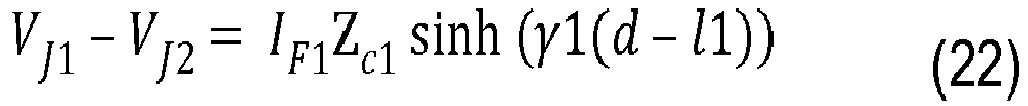
- first junction voltage and the first junction current may be represented in terms of the first fault voltage and first fault current as below:
- V J 1 V F 1 cosh ⁇ 1 d ⁇ l 1 ⁇ I F 1 Z c 1 sinh ⁇ 1 d ⁇ l 1 and
- I J 1 I F 1 cosh ⁇ 1 d ⁇ l 1 ⁇ V F 1 1 Z c 1 sinh ⁇ 1 d ⁇ l 1
- the first junction voltage and the first junction current may be represented as below:
- V J 1 V 1 cosh ⁇ 1 l 1 ⁇ I 1 Z c 1 sinh ⁇ 1 l 1 + I F 1 Z c 1 sinh ⁇ 1 d ⁇ l 1
- I J 1 I 1 cosh ⁇ 1 l 1 ⁇ V 1 1 Z c 1 sinh ⁇ 1 l 1 ⁇ I F 1 sinh ⁇ 1 d ⁇ l 1
- the equation (22) represents the junction voltage parameter and the equation (23) represents the junction current parameter.
- ⁇ 1 is the real part of the propagation constant ⁇ 1, and may be referred to as an attenuation constant of the first section 116.
- ⁇ 1 is the imaginary part or angle of the propagation constant ⁇ 1, and may be referred to as a phase constant of the first section 116.
- the ratio is a complex number. Further, since the values of k, ⁇ 1, and ⁇ 1 are positive, it can be understood that a sign (whether positive or negative) of the ratio depends on the value of ( d - l 1). In other words, if ( d - l 1) is greater than zero, both of a real part of the ratio and an imaginary part of the ratio are greater than zero. If, on the other hand, ( d - l 1) is lesser than zero, both of the real part of the ratio and the imaginary part of the ratio are lesser than zero.
- ( d - l 1) will be lesser than zero if the location 122 of the fault is in the first section 116, i.e., between the first terminal 104 and the junction 120 (as d ⁇ l 1), as illustrated in Fig. 1 . Contrarily, ( d - l 1) will be greater than zero if the location 122 of the fault is in the second section 118. Therefore, to determine whether the fault is in the first section 116 or the second section 118, the ratio may be computed using the equations (7) - (15). Subsequently, it may be checked whether the real part of the ratio or the imaginary part of the ratio is greater or lesser than zero.
- the real part or the imaginary part is lesser than zero, it may be determined that the fault has occurred in the first section 116. If, on the other hand, the real part or the imaginary part is greater than zero, it may be determined that the fault has occurred in the second section 118.
- the imaginary part alone may be used, as generally, the value of the imaginary part is very high, and can be used to accurately identify the section having the fault, even if the location 122 is close to the junction 120 (when d is almost equal to l 1).
- the section of the power transmission line 102 that has a fault can be identified.
- the computations of the first junction voltage, first junction current, second junction voltage and a second junction current, and the ratio and the identification of the faulty section may be performed by the fault section identification module 128.
- the tripping module 130 may determine whether auto-reclosing is to be enabled or blocked based on the section that is identified as having the fault. As will be known, auto-reclosing may be enabled to close a circuit breaker (not shown in Fig. 1 ) that tripped, after a predetermined period has elapsed subsequent to the tripping. Since most number of faults occurring on the first section 116, which is an OHL section, are likely to be transient in nature, if the fault section identification module 128 determines the fault to be present in the first section 116, the tripping module 130 may enable the auto-reclosing.
- the tripping module 130 may send an auto-reclosing command to the circuit breaker. This ensures fast restoration of power supply that got interrupted due to the tripping of the circuit breaker.
- the faults occurring on the second section 118 which is a UGC section, are non-transient in nature, enabling auto-reclosing may damage the cables of the second section 118, as the fault may be still present on the second section 118. Therefore, when the fault is determined to be in the second section 118, the tripping module 130 blocks the auto-reclosing function.
- the power transmission line is explained as having the first section as the OHL section and the second section as the UGC section, the techniques of the present subject matter can be used in cases where the first section is the UGC section and the second section is the OHL section. Further, although the determination of the section having the fault is explained with reference to a mixed power transmission line having two sections (one OHL section and one UGC section), the determination may be performed even for a mixed power transmission line having more than two sections, such as three sections, as will be explained below:
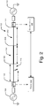
- Fig. 2 illustrates the device 100 for identification of the section having the fault in the power transmission line 102 when the power transmission line 102 has three sections, in accordance with an implementation of the present subject matter.
- the power transmission line 102 includes a third section 202.
- the third section 202 may be connected to the second terminal 110 and may be between the second terminal 110 and the second section 118. Accordingly, a second junction 204 may be present between the second section 118 and the third section 202. Further, the third section 202 may be an OHL section.
- the fault section identification module 128 may compute a third junction voltage and third junction current at the second junction 204 from the first terminal 104. Further, the fault section identification module 128 may also compute a fourth junction voltage and a fourth junction current at the second junction 204 from the second terminal 110.
- the third junction voltage and the third junction current may be computed based on the ABCD parameters of the first section 116 and the ABCD parameters of the second section 118 in the manner as explained with reference to equations (1) - (10).
- the fourth junction voltage and the fourth junction current may be computed based on the ABCD parameters of the third section 202.
- the third junction voltage, third junction current, fourth junction voltage, and fourth junction current may be represented as V J3 , I J3 , V J4 , and I J4 , respectively.
- the second junction voltage and second junction current which are the voltage and current at the junction 120 from the second terminal 110, will depend on the ABCD parameters of both the second section 118 and third section 202.
- a second junction voltage parameter may be computed.
- a second junction current parameter may be computed.
- the second ratio may be represented in terms of the distance of the location 122 of the fault from the first terminal 104 as below:
- R 2 k ⁇ 1 + j ⁇ 1 d ⁇ l 1 + l 2
- the section having the fault may then be identified. For instance, as explained earlier, if the real or imaginary part of the ratio is less than zero, it may be determined that the fault is present in the first section 116. If the real or imaginary part of the ratio is greater than zero, the fault may be present either in the second section 118 or the third section 202, as, in both situations, the distance of the location 122 of the fault from the first terminal 104 (d) is greater than the length of the first section ( l 1). Therefore, the value of the real or imaginary part of the second ratio is checked.
- the fault may be determined to be present between the junction 120 and the second junction 204, i.e., in the second section 118. This is because, in this case, the distance of the location 122 of the fault (d) is lesser than the distance of the second junction 204 from the first terminal 104 ( l 1 + l 2). Thus, ( d - ( l 1 + l 2)) is lesser than zero, and, as per equation (30), the second ratio is lesser than zero.
- the fault may be determined to be present between the second junction 204 and the second terminal 110, i.e., in the third section 202. This is because, in this case, the distance of the location 122 of the fault (d) is greater than the distance of the second junction 204 from the first terminal 104 ( l 1 + l 2).
- FIG. 2 has been explained with respect to a scenario in which the third section 202 is between second section 118 and the second terminal 110, it will be understood that the present subject matter can be utilized even in cases in which the third section 202 is between the first terminal 104 and the first section 116. Accordingly, the second junction 204 may be present between the third section 202 and the first section 116.
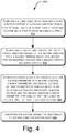
- Figs. 3 and 4 illustrate methods 300 and 400, respectively, for identification of a section of a power transmission line having a fault, in accordance with implementations of the present subject matter.
- the power transmission line includes a first terminal and a second terminal, a first section and a second section between the first terminal and the second terminal, and a junction between first section and the second section.
- the first section may be an overhead line (OHL) section and the second section may be an underground cable (UGC) section.
- the power transmission line may be, for example, the power transmission line 102, having the first terminal 104, second terminal 110, first section 116, second section 118, and junction 120.
- the methods 300 and 400 may be performed by components of the device 100.
- the orders in which the methods 300 and 400 are described are not intended to be construed as a limitation, and any number of the described method blocks may be combined in any order to implement the methods 300 and 400, or an alternative method.
- the methods 300 and 400 may be implemented by processor(s) or computing device(s) through any suitable hardware, non-transitory machine-readable instructions, or a combination thereof.
- steps of the methods 300 and 400 may be performed by programmed computing devices and may be executed based on instructions stored in a non-transitory computer readable medium. Although the methods 300 and 400 may be implemented in a variety of systems, the methods 300 and 400 are described in relation to the device 100, for ease of explanation.
- a first positive sequence voltage and a first positive sequence current at the first terminal are computed based on a first voltage and a first current, respectively, at the first terminal.
- the first positive sequence voltage is computed based on the first voltage
- the first positive sequence current is computed based on the first current.
- the first positive sequence voltage and the first positive sequence current may be V 1 and I 1 as explained earlier.
- a second positive sequence voltage and a second positive sequence current at the second terminal are obtained.
- the second positive sequence voltage depends on a second voltage at the second terminal and the second positive sequence current depends on a second current at the second terminal.
- the second positive sequence voltage and the second positive sequence current may be V 2 and I 2 as explained earlier.
- the obtaining of the second positive sequence voltage and second positive sequence current may include receiving the second positive sequence voltage and second positive sequence current from a second device, such as the second device 138, or computing the second positive sequence voltage and second positive sequence current by the device 100.
- the device 100 may utilize the phasor computation module 126.
- a first junction voltage and a first junction current at the junction from the first terminal are computed based on the first positive sequence voltage and the first positive sequence current.
- the first junction voltage and the first junction current may be V J1 and I J1 , respectively, as explained earlier.
- the computation may be performed using equations (9) and (10). Accordingly, the first junction voltage and the first junction current may be computed based on a length of the first section ( l 1), propagation constant of the first section ( ⁇ 1), and characteristic impedance of the first section (Z C1 ).
- a second junction voltage and a second junction current at the junction from the second terminal is computed based on the second positive sequence voltage and the second positive sequence current.
- the second junction voltage and the second junction current may be V J2 and I J2 , respectively, as explained earlier.
- the computation may be performed using equations (11) and (12). Accordingly, the second junction voltage and the second junction current may be computed based on a length of the second section ( l 2), propagation constant of the second section ( ⁇ 2), and characteristic impedance of the second section (Z C2 ).
- a ratio of a junction voltage parameter to a junction current parameter is computed.
- the junction voltage parameter may depend on the first junction voltage and the second junction voltage, and the junction current parameter may depend on the first junction current and the second junction current.
- the junction voltage parameter may be a difference between the first junction voltage and the second junction voltage, and the junction current parameter may be a sum of the first junction current and the second junction current.
- the junction voltage parameter may be JVP1 and may be computed using equation (13) and the junction current parameter may be JCP1 and may be computed using equation (14).
- the section having the fault is identified based on comparison of the ratio with a threshold.
- the ratio is a complex number and the threshold is zero.
- the section having the fault may be identified based on whether an imaginary part of the ratio is lesser than or greater than zero.
- the ratio may be R1, having a real and imaginary part. If the imaginary part of R1 is lesser than zero, the section having the fault may be identified as the first section, and if the imaginary part of R1 is greater than zero, the section having the fault may be identified as the second section, as explained earlier.
- the steps 306-312 may be performed by the fault section identification module 128.
- an auto-reclosing function based on the section that is identified as having the fault, it may be determined whether an auto-reclosing function is to be enabled or blocked. For instance, as explained earlier, if the fault is identified to be in the first section, which is the OHL section, auto-reclosing may be enabled, and if the fault is identified to be in the second section, auto-reclosing may be blocked. The determination of whether to enable or block, and the consequent enabling or blocking may be performed by the tripping module 130.
- the power transmission line may include a third section.
- the third section may be present between the second section and the second terminal.
- a second junction may be between the second section and the third section.
- the third section may be the third section 202, and the second junction may be the second junction 204.
- Fig. 4 illustrates a method 400 for identification of a section having fault when the power transmission line includes three sections, in accordance with an implementation of the present subject matter.
- the steps of the method 400 may be performed by the fault section identification module 128.
- a third junction voltage and a third junction current at the second junction from the first terminal is computed based on the first positive sequence voltage and the first positive sequence current.
- the third junction voltage and third junction current may be V J3 and I J3 , respectively, as explained earlier.
- a fourth junction voltage and a fourth junction current at the second junction from the second terminal is computed based on the second positive sequence voltage and the second positive sequence current.
- the fourth junction voltage and fourth junction current may be V J4 and I J4 , respectively, as explained earlier.
- a second ratio of a second junction voltage parameter to a second junction current parameter is computed.
- the second junction voltage parameter may depend on the third junction voltage and the fourth junction voltage. Further, the second junction current parameter may depend on the third junction current and the fourth junction current.
- the second junction voltage parameter may be JVP2, the second junction current parameter may be JCP2, and the second ratio may be R2 as explained earlier.
- the section having the fault is identified based on the ratio and the second ratio.
- a section of a power transmission line that has a fault can be accurately determined. Consequently, an informed decision as to whether auto-reclosing is to be performed or not can be taken.
- the techniques of the present subject matter are not to be implemented using custom-made hardware devices, and can be implemented using already existing hardware devices, such as IEDs. Further, to implement the techniques of the present subject matter, the device performing the techniques may utilize even a low sampling frequency, such as less than 4 KHz, for sampling voltage and current signals.
Abstract
Description
- The present subject matter relates, in general, to power transmission lines and, in particular, to identification of a section of a power transmission line having a fault.
- Power transmission lines can be used for transmitting electric power from generating stations that generate electric power to consumers of the electric power. A power transmission line may include a plurality of sections, such as an overhead line (OHL) section and an underground cable (UGC) section. Sometimes, a section of the power transmission line may have a fault, such as a phase-to-ground fault or a phase-to-phase fault.
- The features, aspects, and advantages of the present subject matter will be better understood with regard to the following description, and accompanying figures. The use of the same reference number in different figures indicates similar or identical features and components.
-
Fig. 1 illustrates a device for identifying a section of a power transmission line having a fault, in accordance with an implementation of the present subject matter. -
Fig. 2 illustrates a device for identification of a section having a fault in a power transmission line when the power transmission line has three sections, in accordance with an implementation of the present subject matter. -
Fig. 3 illustrates a method for identification of a section of a power transmission line having a fault, in accordance with an implementation of the present subject matter. -
Fig. 4 illustrates a method for identification of a section having fault when a power transmission line includes three sections, in accordance with an implementation of the present subject matter. - The present subject matter relates to systems and methods for identification of a section of a power transmission line that has a fault.
- A power transmission line may include more than one section. For example, the power transmission line may include an overhead line (OHL) section and an underground cable (UGC) section joined together at a junction. A power transmission line having both an OHL section and a UGC section may be referred to as a mixed power transmission line.
- Sometimes, electrical faults, commonly referred to as faults, may occur on the power transmission lines. In case of a mixed power transmission line, the fault may occur in any section, such as in the OHL section or UGC section. In such cases, a section on which the fault has occurred may have to be determined. One reason for performing the determination is to decide whether auto-reclosing of a circuit breaker on the power transmission line is to be performed or not. For instance, since, generally, faults on the OHL section are transient in nature, auto-reclosing can be performed for a fault in the OHL section for a fast restoration of power supply. Contrarily, since faults in the UGC section are generally non-transient in nature, auto-reclosing may not be performed for a fault on the UGC section to prevent damage to the UGC.
- However, the correct identification of the section having the fault may not be possible, for example, due to different surge impedances of the OHL section and the UGC section.
- The present subject matter relates to systems and methods for identification of a section of a power transmission line that has a fault. The systems and methods of the present subject matter can be used for accurately identifying a section of a mixed power transmission line that is having a fault.
- In an implementation of the present subject matter, a first positive sequence voltage and a first positive sequence current at a first terminal of a power transmission line are computed based on a first voltage and a first current, respectively, at the first terminal. In addition to the first terminal, the power transmission line also includes a second terminal, a first section and second section between the first terminal and second terminal, and a junction between the first terminal and the second terminal. The first section may be an overhead line (OHL) section and a second line may be an underground cable (UGC) section.
- Further, a second positive sequence voltage and a second positive sequence current at the second terminal may be computed based on a second voltage and a second current, respectively, at the second terminal. Based on the first positive sequence voltage and first positive sequence current, a first junction voltage and a first junction current at the junction from the first terminal are computed. Further, a second junction voltage and a second junction current at the junction from the second terminal are also computed.
- Subsequently, a ratio of a junction voltage parameter to a junction current parameter is computed. The junction voltage parameter depends on the first junction voltage and the second junction voltage. Similarly, the junction current parameter depends on the first junction current and the second junction current. Based on the ratio, the section having the fault may then be identified.
- With the systems and methods of the present subject matter, a section of a power transmission line that has a fault can be accurately identified. Consequently, an informed decision as to whether auto-reclosing is to be enabled or not can be taken. Further, to implement the techniques of the present subject matter, a device performing the techniques may utilize even a low sampling frequency, such as less than 4 KHz, for sampling voltage and current signals.
- The above and other features, aspects, and advantages of the subject matter will be better explained with regard to the following description, appended claims, and accompanying figures.
-
Fig. 1 illustrates adevice 100 for identifying a section of apower transmission line 102 having a fault, in accordance with an implementation of the present subject matter. The section that has a fault may be interchangeably referred to as a faulty section. Thedevice 100 may be implemented as any computing device which may be, but is not restricted to, a server, a workstation, a desktop computer, a laptop, and an application. In an example, thedevice 100 may be an Intelligent Electronic Device (IED), which is a device used to control power system equipment, such as a circuit breaker, disconnector, transformer, and the like. - The
power transmission line 102 may be used to transmit electric power. The electric power transmitted may be at high voltages, such as in the range of kilovolts, and for long distances, such as for tens or hundreds of kilometres. Thepower transmission line 102 includes afirst terminal 104 at which thepower transmission line 102 receives electric power from a firstelectric generator 106. Thefirst terminal 104 may also be referred to as afirst bus 104. An internal impedance of the firstelectrical generator 106 is represented by afirst impedance 108. Thepower transmission line 102 also includes asecond terminal 110 at which thepower transmission line 102 receives electric power from a secondelectrical generator 112. Thesecond terminal 110 may also be referred to as asecond bus 110. An internal impedance of the secondelectrical generator 112 is represented as asecond impedance 114. - Between the
first terminal 104 and thesecond terminal 110, thepower transmission line 102 may include a plurality of sections and a junction between two of the plurality of sections. For example, thepower transmission line 102 includes afirst section 116 that is an overhead line (OHL) section and asecond section 118 that is an underground cable (UGC) section. Since thepower transmission line 102 includes both an OHL section and UGC section, thepower transmission line 102 may be referred to as a mixed power transmission line. Thefirst section 116 and thesecond section 118 may be joined at ajunction 120. - Sometimes, an electrical fault, commonly referred to as a fault, may occur on the
power transmission line 102. For example, as illustrated inFig. 1 , the fault may occur at alocation 122 of thepower transmission line 102. The fault may be, for example, a phase-to-ground fault or a phase-to-phase fault. Since thepower transmission line 102 is a mixed power transmission line, the identification of a faulty section, i.e., whether the fault is present in thefirst section 116 or thesecond section 118, may not be a straightforward task. This may be because of different surge impedances of thefirst section 116 and thesecond section 118. - To facilitate identification of the section having the fault, the
device 100 may utilize various components, such as aninput interface 124, aphasor computation module 126, and a fault section identification module 128. In addition, thedevice 100 may also include atripping module 130. Each of thephasor computation module 126, fault section identification module 128, andtripping module 130 may be coupled to aprocessor 132. Further, thephasor computation module 126, fault section identification module 128, and trippingmodule 130 may be implemented in hardware, instructions executed by theprocessor 132, or by a combination thereof. - In operation, the
input interface 124 may obtain measurements of a first voltage at thefirst terminal 104 and a first current at thefirst terminal 104. For this, theinput interface 124 may include input modules that can receive and process the measurements of the voltage and current in the form of analog signals. Such input modules may be connected toinstrument transformers 134, which, in turn, are connected to thefirst terminal 104 of thepower transmission line 102. Theinstrument transformers 134 may include a voltage transformer and a current transformer, which measure the first voltage and the first current, respectively. - The
input interface 124 may also obtain measurements of a second voltage and a second current at thesecond terminal 110. For this, in an example, theinput interface 124 may receive the measurements of the second voltage and the second current from asecond device 138. Thesecond device 138 may be, for example, an IED, and may be interchangeably referred to as thesecond IED 138. Thesecond device 138 may be connected at thesecond terminal 110 throughinstrument transformers 140. The measurements of the second voltage and the second current may be received from thesecond device 138 in the form of analog signals through acommunication link 142 between thedevice 100 and thesecond device 138. Thecommunication link 142 may be, for example, a fibre optic link. - Based on the first voltage and first current, the
phasor computation module 126 may compute, respectively, a positive sequence voltage phasor and a positive sequence current phasor. For instance, based on the first voltage, the positive sequence voltage phasor may be computed, and based on the first current, the positive sequence current phasor may be computed. The positive sequence voltage phasor and positive sequence current phasor are positive sequence voltage at thefirst terminal 104 and positive sequence current flowing from thefirst terminal 104, respectively, subsequent to the fault. The positive sequence voltage phasor may be referred to as the first positive sequence voltage phasor or first positive sequence voltage. Further, the positive sequence current phasor may be referred to as the first positive sequence current phasor or first positive sequence current. The first positive sequence voltage and the first positive sequence current may be represented as V1 and I1, respectively. To compute the first positive sequence voltage and first positive sequence current, thephasor computation module 126 may utilize any suitable phasor estimation technique. - The
phasor computation module 126 may also compute positive sequence voltage phasor at thesecond terminal 110 and positive sequence current phasor flowing from thesecond terminal 110 subsequent to the fault, based on the second voltage and second current, respectively. For instance, based on the second voltage, the positive sequence voltage phasor at thesecond terminal 110 may be computed, and based on the second current, positive sequence current phasor at the second terminal may be computed. The positive sequence voltage phasor at thesecond terminal 110 may be referred to as second positive sequence voltage phasor or second positive sequence voltage. Further, the positive sequence current phasor flowing from thesecond terminal 110 may be referred to as second positive sequence current phasor or second positive sequence current. The second positive sequence voltage and second positive sequence current may be represented as V2 and I2, respectively. - In an implementation, instead of computing the second positive sequence voltage and the second positive sequence current, the
device 100 may receive the second positive sequence voltage and the second positive sequence current from thesecond device 138. For this, thesecond device 138 may compute the second positive sequence voltage and the second positive sequence current based on the second voltage and the second current. Subsequently, thesecond device 138 may send, instead of the second voltage and second current, the second positive sequence voltage and the second positive sequence current to thedevice 100. - Based on the first positive sequence voltage and first positive sequence current, a voltage and a current at the
junction 120 from thefirst terminal 104 are computed. The voltage and the current at thejunction 120 from thefirst terminal 104 are referred to as the first junction voltage and the first junction current, respectively, and may be represented as VJ1 and IJ1, respectively. Similarly, a second junction voltage and a second junction current at thejunction 120 from thesecond terminal 110 are computed based on the second positive sequence voltage and second positive sequence current. The second junction voltage and the second junction current may be represented as VJ2 and IJ2, respectively. The computation of VJ1, IJ1, VJ2, and IJ2, is explained below: - As is well known, a power transmission line can be mathematically modelled using its line impedance parameters commonly referred to as ABCD parameters. The parameters A, B, C, and D can be computed using the below equations:


- Therefore, for the
first section 116 of thepower transmission line 102, equations (1) and (2) may be written as follows:
first section 116. - It is also known that the values of the ABCD parameters may be computed as per the below equations:


first section 116, l1 is a length of thefirst section 116, and ZC1 is a characteristic impedance of thefirst section 116. γ1 and ZC1 may be computed using the below equations:

first section 116. - Substituting the values of A1, B1, C1, and D1 from equations (4) - (6) in (3), VJ1 and VJ2 may be obtained as follows:


- Equations (9) and (10) provide the first junction voltage and the first junction current as a function of the first positive sequence voltage and first positive sequence current. Since the first positive sequence voltage and first positive sequence current are already computed, and the characteristic impedance, the propagation constant, and the length of the
first section 116 are known constants, the first junction voltage and the first junction current may be computed using equations (9) and (10), respectively. - Similar to equations (9) and (10), the second junction voltage and second junction current may be written as a function of the second positive sequence voltage and second positive sequence current as below:


second section 118, l2 is a length of thesecond section 118, and ZC2 is a characteristic impedance of thesecond section 118. - Using equations (11) and (12), the second junction voltage and second junction current may then be computed.
- Upon computing the first junction voltage and second junction voltage, a junction voltage parameter is computed based on the first junction voltage and second junction voltage. In an example, the junction voltage parameter is a difference between the first junction voltage and second junction voltage, as represented below:

- Further, using the first junction current and second junction current, a junction current parameter may be computed. In an example, the junction current parameter is a sum of the first junction current and second junction current, as represented below:

- Thereafter, a ratio of the junction voltage parameter to the junction current parameter is computed, as represented below:

- The ratio may be used to identify the section having the fault. In other words, the ratio may be used to determine whether the fault is in the
first section 116 or thesecond section 118. This will be explained below: - Similar to the first junction voltage and the first junction current, the voltage and current at a location of the fault, i.e., at the
location 122, from thefirst terminal 104 may be written as a function of the first positive sequence voltage and first positive sequence current as follows:

location 122 from thefirst terminal 104, IF1 is the current at thelocation 122 from thefirst terminal 104, and d is the distance of the fault from thefirst terminal 104. VF1 and IF1 may also be referred to as first fault voltage and first fault current, respectively. - Further, the first junction voltage and the first junction current may be represented in terms of the first fault voltage and first fault current as below:


- Expanding the sin and cos hyperbolic functions in equations (18) and (19) and rearranging, the first junction voltage and the first junction current may be represented as below:


- Using equations (11), (12), (20), and (21), the below equations may be obtained:

- As will be understood, the equation (22) represents the junction voltage parameter and the equation (23) represents the junction current parameter. Thus, the ratio may be written as below:

- Since γ1 is a complex number, tanh (γ1(d - l1)) is also a complex number, and may be written as tanh (A + jB), where A and B are constants. Further, since tanh (A + jB) is another complex number, say C + jD, that depends on (A + jB), it may be concluded that R1 is proportional to (γ1(d - l1)). Therefore, the ratio may be written as below:

- Equation (25) may be re-written as below:

first section 116. Further, β1 is the imaginary part or angle of the propagation constant γ1, and may be referred to as a phase constant of thefirst section 116. - From equation (26), it can be seen that the ratio is a complex number. Further, since the values of k, α1, and β1 are positive, it can be understood that a sign (whether positive or negative) of the ratio depends on the value of (d - l1). In other words, if (d - l1) is greater than zero, both of a real part of the ratio and an imaginary part of the ratio are greater than zero. If, on the other hand, (d - l1) is lesser than zero, both of the real part of the ratio and the imaginary part of the ratio are lesser than zero.
- As will be understood, (d - l1) will be lesser than zero if the
location 122 of the fault is in thefirst section 116, i.e., between thefirst terminal 104 and the junction 120 (as d < l1), as illustrated inFig. 1 . Contrarily, (d - l1) will be greater than zero if thelocation 122 of the fault is in thesecond section 118. Therefore, to determine whether the fault is in thefirst section 116 or thesecond section 118, the ratio may be computed using the equations (7) - (15). Subsequently, it may be checked whether the real part of the ratio or the imaginary part of the ratio is greater or lesser than zero. If the real part or the imaginary part is lesser than zero, it may be determined that the fault has occurred in thefirst section 116. If, on the other hand, the real part or the imaginary part is greater than zero, it may be determined that the fault has occurred in thesecond section 118. - In an example, for identifying the faulty section, the imaginary part alone may be used, as generally, the value of the imaginary part is very high, and can be used to accurately identify the section having the fault, even if the
location 122 is close to the junction 120 (when d is almost equal to l1). - Thus, using the ratio, the section of the
power transmission line 102 that has a fault can be identified. In an implementation, the computations of the first junction voltage, first junction current, second junction voltage and a second junction current, and the ratio and the identification of the faulty section may be performed by the fault section identification module 128. - Upon identifying the section having the fault, the tripping
module 130 may determine whether auto-reclosing is to be enabled or blocked based on the section that is identified as having the fault. As will be known, auto-reclosing may be enabled to close a circuit breaker (not shown inFig. 1 ) that tripped, after a predetermined period has elapsed subsequent to the tripping. Since most number of faults occurring on thefirst section 116, which is an OHL section, are likely to be transient in nature, if the fault section identification module 128 determines the fault to be present in thefirst section 116, the trippingmodule 130 may enable the auto-reclosing. Subsequently, the trippingmodule 130 may send an auto-reclosing command to the circuit breaker. This ensures fast restoration of power supply that got interrupted due to the tripping of the circuit breaker. On the other hand, since the faults occurring on thesecond section 118, which is a UGC section, are non-transient in nature, enabling auto-reclosing may damage the cables of thesecond section 118, as the fault may be still present on thesecond section 118. Therefore, when the fault is determined to be in thesecond section 118, the trippingmodule 130 blocks the auto-reclosing function. - Although the power transmission line is explained as having the first section as the OHL section and the second section as the UGC section, the techniques of the present subject matter can be used in cases where the first section is the UGC section and the second section is the OHL section. Further, although the determination of the section having the fault is explained with reference to a mixed power transmission line having two sections (one OHL section and one UGC section), the determination may be performed even for a mixed power transmission line having more than two sections, such as three sections, as will be explained below:
-
Fig. 2 illustrates thedevice 100 for identification of the section having the fault in thepower transmission line 102 when thepower transmission line 102 has three sections, in accordance with an implementation of the present subject matter. As illustrated, in addition to thefirst section 116 and thesecond section 118, thepower transmission line 102 includes athird section 202. Thethird section 202 may be connected to thesecond terminal 110 and may be between thesecond terminal 110 and thesecond section 118. Accordingly, asecond junction 204 may be present between thesecond section 118 and thethird section 202. Further, thethird section 202 may be an OHL section. - In the above case, the fault section identification module 128 may compute a third junction voltage and third junction current at the
second junction 204 from thefirst terminal 104. Further, the fault section identification module 128 may also compute a fourth junction voltage and a fourth junction current at thesecond junction 204 from thesecond terminal 110. - The third junction voltage and the third junction current may be computed based on the ABCD parameters of the
first section 116 and the ABCD parameters of thesecond section 118 in the manner as explained with reference to equations (1) - (10). Similarly, the fourth junction voltage and the fourth junction current may be computed based on the ABCD parameters of thethird section 202. The third junction voltage, third junction current, fourth junction voltage, and fourth junction current may be represented as VJ3, IJ3, VJ4, and IJ4, respectively. - As will be understood, when the
third section 202 is between thesecond terminal 110 and thesecond section 118 as illustrated, the second junction voltage and second junction current, which are the voltage and current at thejunction 120 from thesecond terminal 110, will depend on the ABCD parameters of both thesecond section 118 andthird section 202. - Based on the third junction voltage and fourth junction voltage, a second junction voltage parameter may be computed. For example, the second junction voltage parameter may be a difference between the third junction voltage and fourth junction voltage, as represented below:

- Further, based on the third junction current and fourth junction current, a second junction current parameter may be computed. In an example, the second junction current parameter is a sum of the third junction current and fourth junction current, as represented below:

- Subsequently, a second ratio of the second junction voltage parameter to the second junction current parameter may be computed, as represented below:

- Similar to the equation (26), the second ratio may be represented in terms of the distance of the
location 122 of the fault from thefirst terminal 104 as below:
- Based on the values of the ratio and the second ratio, the section having the fault may then be identified. For instance, as explained earlier, if the real or imaginary part of the ratio is less than zero, it may be determined that the fault is present in the
first section 116. If the real or imaginary part of the ratio is greater than zero, the fault may be present either in thesecond section 118 or thethird section 202, as, in both situations, the distance of thelocation 122 of the fault from the first terminal 104 (d) is greater than the length of the first section (l1). Therefore, the value of the real or imaginary part of the second ratio is checked. - If the value of the real or imaginary part of the second ratio is lesser than zero, the fault may be determined to be present between the
junction 120 and thesecond junction 204, i.e., in thesecond section 118. This is because, in this case, the distance of thelocation 122 of the fault (d) is lesser than the distance of thesecond junction 204 from the first terminal 104 (l1 + l2). Thus, (d - (l1 + l2)) is lesser than zero, and, as per equation (30), the second ratio is lesser than zero. - If the value of the real or imaginary part of the second ratio is greater than zero, the fault may be determined to be present between the
second junction 204 and thesecond terminal 110, i.e., in thethird section 202. This is because, in this case, the distance of thelocation 122 of the fault (d) is greater than the distance of thesecond junction 204 from the first terminal 104 (l1 + l2). - Although
Fig. 2 has been explained with respect to a scenario in which thethird section 202 is betweensecond section 118 and thesecond terminal 110, it will be understood that the present subject matter can be utilized even in cases in which thethird section 202 is between thefirst terminal 104 and thefirst section 116. Accordingly, thesecond junction 204 may be present between thethird section 202 and thefirst section 116. -
Figs. 3 and4 illustratemethods power transmission line 102, having thefirst terminal 104,second terminal 110,first section 116,second section 118, andjunction 120. Further, themethods device 100. - The orders in which the
methods methods methods - It may be understood that steps of the
methods methods methods device 100, for ease of explanation. - Referring to
method 300, at step 302, a first positive sequence voltage and a first positive sequence current at the first terminal are computed based on a first voltage and a first current, respectively, at the first terminal. For instance, the first positive sequence voltage is computed based on the first voltage and the first positive sequence current is computed based on the first current. The first positive sequence voltage and the first positive sequence current may be V1 and I1 as explained earlier. - At
step 304, a second positive sequence voltage and a second positive sequence current at the second terminal are obtained. The second positive sequence voltage depends on a second voltage at the second terminal and the second positive sequence current depends on a second current at the second terminal. The second positive sequence voltage and the second positive sequence current may be V2 and I2 as explained earlier. The obtaining of the second positive sequence voltage and second positive sequence current may include receiving the second positive sequence voltage and second positive sequence current from a second device, such as thesecond device 138, or computing the second positive sequence voltage and second positive sequence current by thedevice 100. To compute the second positive sequence voltage and second positive sequence current, thedevice 100 may utilize thephasor computation module 126. - At
step 306, a first junction voltage and a first junction current at the junction from the first terminal are computed based on the first positive sequence voltage and the first positive sequence current. The first junction voltage and the first junction current may be VJ1 and IJ1, respectively, as explained earlier. The computation may be performed using equations (9) and (10). Accordingly, the first junction voltage and the first junction current may be computed based on a length of the first section (l1), propagation constant of the first section (γ1), and characteristic impedance of the first section (ZC1). - At
step 308, a second junction voltage and a second junction current at the junction from the second terminal is computed based on the second positive sequence voltage and the second positive sequence current. The second junction voltage and the second junction current may be VJ2 and IJ2, respectively, as explained earlier. The computation may be performed using equations (11) and (12). Accordingly, the second junction voltage and the second junction current may be computed based on a length of the second section (l2), propagation constant of the second section (γ2), and characteristic impedance of the second section (ZC2). - At
step 310, a ratio of a junction voltage parameter to a junction current parameter is computed. The junction voltage parameter may depend on the first junction voltage and the second junction voltage, and the junction current parameter may depend on the first junction current and the second junction current. The junction voltage parameter may be a difference between the first junction voltage and the second junction voltage, and the junction current parameter may be a sum of the first junction current and the second junction current. The junction voltage parameter may be JVP1 and may be computed using equation (13) and the junction current parameter may be JCP1 and may be computed using equation (14). - At
step 312, the section having the fault is identified based on comparison of the ratio with a threshold. In an example, the ratio is a complex number and the threshold is zero. Accordingly, the section having the fault may be identified based on whether an imaginary part of the ratio is lesser than or greater than zero. For instance, the ratio may be R1, having a real and imaginary part. If the imaginary part of R1 is lesser than zero, the section having the fault may be identified as the first section, and if the imaginary part of R1 is greater than zero, the section having the fault may be identified as the second section, as explained earlier. - The steps 306-312 may be performed by the fault section identification module 128.
- In an implementation, based on the section that is identified as having the fault, it may be determined whether an auto-reclosing function is to be enabled or blocked. For instance, as explained earlier, if the fault is identified to be in the first section, which is the OHL section, auto-reclosing may be enabled, and if the fault is identified to be in the second section, auto-reclosing may be blocked. The determination of whether to enable or block, and the consequent enabling or blocking may be performed by the tripping
module 130. - In an implementation, in addition to the first section and second section, the power transmission line may include a third section. The third section may be present between the second section and the second terminal. Further, a second junction may be between the second section and the third section. the third section may be the
third section 202, and the second junction may be thesecond junction 204. The identification of the section having the fault in such a case is explained with reference toFig. 4 . -
Fig. 4 illustrates amethod 400 for identification of a section having fault when the power transmission line includes three sections, in accordance with an implementation of the present subject matter. The steps of themethod 400 may be performed by the fault section identification module 128. - At
step 402, a third junction voltage and a third junction current at the second junction from the first terminal is computed based on the first positive sequence voltage and the first positive sequence current. The third junction voltage and third junction current may be VJ3 and IJ3, respectively, as explained earlier. - At
step 404, a fourth junction voltage and a fourth junction current at the second junction from the second terminal is computed based on the second positive sequence voltage and the second positive sequence current. The fourth junction voltage and fourth junction current may be VJ4 and IJ4, respectively, as explained earlier. - At
step 406, a second ratio of a second junction voltage parameter to a second junction current parameter is computed. The second junction voltage parameter may depend on the third junction voltage and the fourth junction voltage. Further, the second junction current parameter may depend on the third junction current and the fourth junction current. The second junction voltage parameter may be JVP2, the second junction current parameter may be JCP2, and the second ratio may be R2 as explained earlier. - At
step 408, the section having the fault is identified based on the ratio and the second ratio. - With the systems and methods of the present subject matter, a section of a power transmission line that has a fault can be accurately determined. Consequently, an informed decision as to whether auto-reclosing is to be performed or not can be taken. The techniques of the present subject matter are not to be implemented using custom-made hardware devices, and can be implemented using already existing hardware devices, such as IEDs. Further, to implement the techniques of the present subject matter, the device performing the techniques may utilize even a low sampling frequency, such as less than 4 KHz, for sampling voltage and current signals.
- Although the present subject matter has been described with reference to specific embodiments, this description is not meant to be construed in a limiting sense. Various modifications of the disclosed embodiments, as well as alternate embodiments of the subject matter, will become apparent to persons skilled in the art upon reference to the description of the subject matter. Further, although the present subject matter has been explained with reference to specific configurations of a mixed power transmission line, it is to be understood that the present subject matter can be used for any configuration of mixed power transmission lines.
Claims (10)
- A method for identifying a section of a power transmission line (102) having a fault, the power transmission line (102) having a first terminal (104), a second terminal (110), a first section (116) and a second section (118) between the first terminal (104) and the second terminal (110), and a junction (120) between first section (116) and the second section (118), the first section (116) being an overhead line (OHL) section and the second section (118) being an underground cable (UGC) section, and the method comprising:computing a first positive sequence voltage and a first positive sequence current at the first terminal (104) based on a first voltage and a first current, respectively, at the first terminal (104);obtaining a second positive sequence voltage and a second positive sequence current at the second terminal (110), wherein the second positive sequence voltage depends on a second voltage at the second terminal (110) and the second positive sequence current depends on a second current at the second terminal (110);computing a first junction voltage and a first junction current at the junction (120) from the first terminal (104) based on the first positive sequence voltage and the first positive sequence current;computing a second junction voltage and a second junction current at the junction (120) from the second terminal (110) based on the second positive sequence voltage and the second positive sequence current;computing a ratio of a junction voltage parameter to a junction current parameter, the junction voltage parameter depending on the first junction voltage and the second junction voltage, and the junction current parameter depending on the first junction current and the second junction current; andidentifying the section having the fault based on comparison of the ratio with a threshold.
- The method as claimed in claim 1 or 2, wherein the junction voltage parameter is a difference between the first junction voltage and the second junction voltage, and the junction current parameter is a sum of the first junction current and the second junction current.
- The method as claimed in one of the previous claims, wherein the ratio is a complex number, the threshold is zero, and the method comprises identifying the section having the fault based on whether an imaginary part of the ratio is lesser than or greater than zero.
- The method as claimed in one of the previous claims, whereinthe power transmission line (102) comprises a third section (202) between the second section (118) and the second terminal (110) and a second junction (204) between the second section (118) and the third section (202), andthe method comprises:computing a third junction voltage and a third junction current at the second junction (204) from the first terminal (104) based on the first positive sequence voltage and the first positive sequence current;computing a fourth junction voltage and a fourth junction current at the second junction (204) from the second terminal (110) based on the second positive sequence voltage and the second positive sequence current;computing a second ratio of a second junction voltage parameter to a second junction current parameter, the second junction voltage parameter depending on the third junction voltage and the fourth junction voltage, and the second junction current parameter depending on the third junction current and the fourth junction current; andidentifying the section having the fault based on the ratio and the second ratio.
- The method as claimed in one of the previous claims, comprisingcomputing the first junction voltage and the first junction current based on a length of the first section, propagation constant of the first section, and characteristic impedance of the first section; andcomputing the second junction voltage and the second junction current based on a length of the second section, propagation constant of the second section, and characteristic impedance of the second section.
- The method as claimed in one of the previous claims, comprising determining whether
auto-reclosing is to be enabled or blocked based on the section having the fault. - A device (100) for identifying a section of a power transmission line (102) having a fault, the power transmission line (102) having a first terminal (104), a second terminal (110), a plurality of sections between the first terminal (104) and the second terminal (110), and a junction (120) between two of the plurality of sections, and the device (100) comprising:an input interface (124) to:obtain measurements of a first voltage and a first current at the first terminal (104);obtain measurements of a second voltage and a second current at the second terminal (110);a phasor computation module (126) to:compute a first positive sequence voltage phasor and a first positive sequence current phasor at the first terminal (104) based on the first voltage and the first current, respectively;compute a second positive sequence voltage phasor and a second positive sequence current phasor at the second terminal (110) based on the second voltage and the second current, respectively;a fault section identification (128) module to:compute a first junction voltage and a first junction current at the junction from the first terminal (104) based on the first positive sequence voltage phasor and the first positive sequence current phasor;compute a second junction voltage and a second junction current at the junction from the second terminal (110) based on the second positive sequence voltage phasor and the second positive sequence current phasor;compute a ratio of a junction voltage parameter to a junction current parameter, the junction voltage parameter depending on the first junction voltage and the second junction voltage, and the junction current parameter depending on the first junction current and the second junction current; andidentify the section having the fault based on the ratio.
- The device (100) as claimed in claim 7, comprising a tripping module (130) to:determine whether auto-reclosing is to be enabled or blocked based on the section having the fault; andgenerating an auto-reclosing command to be sent to a circuit breaker on the power transmission line if auto-reclosing is determined to be enabled.
- The device (100) as claimed in claim 7 or 8, wherein the device is an intelligent electronic device (IED) and the input interface (124) is to obtain the measurements of the second voltage and second current from a second IED (138) connected to the second terminal (110).
- The device (100) as claimed in one of the previous claims 7 to 9, whereinthe plurality of sections comprises a first section (116) and a second section (118),the first section (116) is an overhead line (OHL) section and the second section (118) is an underground cable (UGC) section,the junction (120) is between the first section (116) and the second section (118),the plurality of sections further comprises a third section (202),the third section (202) is between the first terminal (104) and the first section (116) or between the second section (118) and the second terminal (110),the power transmission line (102) comprises a second junction (204) between the third section (202) and the first section (116) or between the second section (118) and the third section (202),the fault section identification module (128) is to compute a second ratio based on a third junction voltage, a third junction current, a fourth junction voltage, and a fourth junction current,the third junction voltage and third junction current are voltage and current, respectively, at the second junction (204) from the first terminal (104),the fourth junction voltage and the fourth junction current are voltage and current, respectively, at the second junction (204) from the second terminal (110), andthe fault section identification module (128) is to identify the section having the fault based on the ratio and the second ratio.
Priority Applications (2)
| Application Number | Priority Date | Filing Date | Title |
|---|---|---|---|
| US16/524,134 US11169195B2 (en) | 2018-07-31 | 2019-07-28 | Identification of faulty section of power transmission line |
| CN201910696004.0A CN110780149A (en) | 2018-07-31 | 2019-07-30 | Identification of faulty sections of a power transmission line |
Applications Claiming Priority (1)
| Application Number | Priority Date | Filing Date | Title |
|---|---|---|---|
| IN201841028697 | 2018-07-31 |
Publications (1)
| Publication Number | Publication Date |
|---|---|
| EP3605765A1 true EP3605765A1 (en) | 2020-02-05 |
Family
ID=63642880
Family Applications (1)
| Application Number | Title | Priority Date | Filing Date |
|---|---|---|---|
| EP18195509.7A Pending EP3605765A1 (en) | 2018-07-31 | 2018-09-19 | Identification of faulty section of power transmission line |
Country Status (3)
| Country | Link |
|---|---|
| US (1) | US11169195B2 (en) |
| EP (1) | EP3605765A1 (en) |
| CN (1) | CN110780149A (en) |
Families Citing this family (5)
| Publication number | Priority date | Publication date | Assignee | Title |
|---|---|---|---|---|
| US10197614B2 (en) * | 2016-05-02 | 2019-02-05 | Schweitzer Engineering Laboratories, Inc. | Fault location during pole-open condition |
| CN111226363B (en) * | 2017-08-04 | 2023-01-06 | 日立能源瑞士股份公司 | Method and device for identifying fault sections in a multi-terminal hybrid line |
| US10859639B2 (en) * | 2018-10-02 | 2020-12-08 | Schweitzer Engineering Laboratories, Inc. | Fault-type identification in an electric power delivery system using composite signals |
| US11735908B2 (en) | 2021-02-15 | 2023-08-22 | Schweitzer Engineering Laboratories, Inc. | Dependable open-phase detection in electric power delivery systems with inverter-based resources |
| US11650241B1 (en) | 2022-06-28 | 2023-05-16 | Schweitzer Engineering Laboratories, Inc. | Incremental quantities-based fault locating technique and system |
Citations (4)
| Publication number | Priority date | Publication date | Assignee | Title |
|---|---|---|---|---|
| US20110037480A1 (en) * | 2007-07-19 | 2011-02-17 | Abb Research Ltd. | Method for fault location in uncompensated power lines with two-end unsynchronized measurement |
| US8942954B2 (en) * | 2010-09-16 | 2015-01-27 | Schweitzer Engineering Laboratories, Inc. | Fault location in a non-homogeneous electric power line |
| CN105699858A (en) * | 2016-04-28 | 2016-06-22 | 国网上海市电力公司 | Aerial-cable hybrid line fault location method considering connector resistance |
| CN108008251A (en) * | 2017-11-29 | 2018-05-08 | 国网江苏省电力公司无锡供电公司 | The fault distance-finding method of mixed power transmission line unknown parameters |
Family Cites Families (10)
| Publication number | Priority date | Publication date | Assignee | Title |
|---|---|---|---|---|
| US20030085715A1 (en) * | 2001-08-15 | 2003-05-08 | David Lubkeman | System and method for locating a fault on ungrounded and high-impedance grounded power systems |
| US8943954B2 (en) * | 2008-12-19 | 2015-02-03 | Whirlpool Corporation | Food processor with cleaning tool |
| CN101907677A (en) * | 2010-07-02 | 2010-12-08 | 华北电力大学 | High voltage cable-overhead line hybrid line fault phase ranging method |
| US10401417B2 (en) * | 2013-02-13 | 2019-09-03 | General Electric Technology Gmbh | Electrical fault location determination in a distribution system based on phasor information |
| CN103792466B (en) * | 2014-02-18 | 2016-06-08 | 国家电网公司 | Overhead transmission line-power cable mixed connection line double-end Fault Locating Method |
| CN103760473B (en) * | 2014-02-18 | 2016-02-10 | 国家电网公司 | Overhead transmission line-power cable mixed connection line fault branch road method of discrimination |
| DK3159990T3 (en) * | 2015-10-22 | 2018-05-07 | General Electric Technology Gmbh | IMPROVEMENTS OR RELATED TO ELECTRIC POWER SYSTEMS |
| WO2017072612A1 (en) * | 2015-10-30 | 2017-05-04 | Abb Schweiz Ag | Method and system for protection in a mixed line |
| US10197614B2 (en) * | 2016-05-02 | 2019-02-05 | Schweitzer Engineering Laboratories, Inc. | Fault location during pole-open condition |
| CN111937264B (en) * | 2018-03-31 | 2024-03-08 | 日立能源有限公司 | Method and apparatus for protection in a multi-terminal power transmission system |
-
2018
- 2018-09-19 EP EP18195509.7A patent/EP3605765A1/en active Pending
-
2019
- 2019-07-28 US US16/524,134 patent/US11169195B2/en active Active
- 2019-07-30 CN CN201910696004.0A patent/CN110780149A/en active Pending
Patent Citations (4)
| Publication number | Priority date | Publication date | Assignee | Title |
|---|---|---|---|---|
| US20110037480A1 (en) * | 2007-07-19 | 2011-02-17 | Abb Research Ltd. | Method for fault location in uncompensated power lines with two-end unsynchronized measurement |
| US8942954B2 (en) * | 2010-09-16 | 2015-01-27 | Schweitzer Engineering Laboratories, Inc. | Fault location in a non-homogeneous electric power line |
| CN105699858A (en) * | 2016-04-28 | 2016-06-22 | 国网上海市电力公司 | Aerial-cable hybrid line fault location method considering connector resistance |
| CN108008251A (en) * | 2017-11-29 | 2018-05-08 | 国网江苏省电力公司无锡供电公司 | The fault distance-finding method of mixed power transmission line unknown parameters |
Also Published As
| Publication number | Publication date |
|---|---|
| US11169195B2 (en) | 2021-11-09 |
| US20200041562A1 (en) | 2020-02-06 |
| CN110780149A (en) | 2020-02-11 |
Similar Documents
| Publication | Publication Date | Title |
|---|---|---|
| US11169195B2 (en) | Identification of faulty section of power transmission line | |
| US11035897B2 (en) | Method and device for fault section identification in multi-terminal mixed lines | |
| EP3482472B1 (en) | A method and system for locating a fault in a mixed power transmission line | |
| EP0459522A2 (en) | Fault location method for a parallel two-circuit transmission line with N terminals | |
| EP3776778B1 (en) | Method and device for protection in a multi-terminal power transmission system | |
| US11114843B2 (en) | Method and system for protection in a mixed line | |
| WO2019166903A1 (en) | Method and device for fault location in a two-terminal transmission system | |
| EP3050185B1 (en) | Method for identifying a faulted dc power transmission medium in a multi-terminal dc electrical network | |
| Han et al. | Fault location on a mixed overhead and underground transmission feeder using a multiple-zone quadrilateral impedance relay and a double-ended travelling wave fault locator | |
| US11327105B2 (en) | Fault location in multi-terminal tapped lines | |
| WO2020026069A1 (en) | Traveling wave based auto-reclosing and fault location method for multi-terminal mixed lines | |
| Di Tomasso et al. | Accurate single-end and double-end fault location by traveling waves: A review with some real applications | |
| EP3767314B1 (en) | Fault location in an hvdc system | |
| Prabhavathi et al. | Detection and location of faults in 11kv underground cable by using continuous wavelet transform (cwt) | |
| George et al. | Traveling wave based autoreclosure scheme for multi-terminal lines | |
| EP4340151A1 (en) | Parameter estimation for multi-terminal lines | |
| Unde et al. | A New Protection Scheme for Three-Terminal Mutually Coupled Transmission Line | |
| Nichols et al. | The effects of earth potential rise on surge arrester specification in specially bonded cable systems | |
| Biasiotti et al. | Impact of the Transformer Stray Capacitances on the Ground Mode Current in Unearthed OHL Networks: Analysis of the Travelling Waves Propagation | |
| Hatata et al. | ADVANCED WIDE AREA FAULT LOCATION AND CLASSIFICATION USING PHASOR MEASUREMENTS UNITS | |
| Adzman | Evaluation of fault location algorithm in distribution power system lines using differential equation method with fault indicator approach | |
| Bustamante-Mparsakis et al. | Fault Locator Using Travelling Waves: Experience in the Belgian Transmission Network | |
| Gunjker et al. | Analysis of fault location for transmission lines | |
| Kamyab et al. | Fault location algorithm for three-terminal transmission lines: distributed time domain line model | |
| Jamil et al. | Wave propagation in a faulty unbalanced EHV line |
Legal Events
| Date | Code | Title | Description |
|---|---|---|---|
| PUAI | Public reference made under article 153(3) epc to a published international application that has entered the european phase |
Free format text: ORIGINAL CODE: 0009012 |
|
| STAA | Information on the status of an ep patent application or granted ep patent |
Free format text: STATUS: REQUEST FOR EXAMINATION WAS MADE |
|
| 17P | Request for examination filed |
Effective date: 20180919 |
|
| AK | Designated contracting states |
Kind code of ref document: A1 Designated state(s): AL AT BE BG CH CY CZ DE DK EE ES FI FR GB GR HR HU IE IS IT LI LT LU LV MC MK MT NL NO PL PT RO RS SE SI SK SM TR |
|
| AX | Request for extension of the european patent |
Extension state: BA ME |
|
| RAP1 | Party data changed (applicant data changed or rights of an application transferred) |
Owner name: ABB POWER GRIDS SWITZERLAND AG |
|
| RBV | Designated contracting states (corrected) |
Designated state(s): AL AT BE BG CH CY CZ DE DK EE ES FI FR GB GR HR HU IE IS IT LI LT LU LV MC MK MT NL NO PL PT RO RS SE SI SK SM TR |
|
| RAP3 | Party data changed (applicant data changed or rights of an application transferred) |
Owner name: HITACHI ENERGY SWITZERLAND AG |
|
| RIN1 | Information on inventor provided before grant (corrected) |
Inventor name: NEETHU, GEORGE Inventor name: NAIDU, OD |
|
| RIN1 | Information on inventor provided before grant (corrected) |
Inventor name: NEETHU, GEORGE Inventor name: NAIDU, OD |
|
| P01 | Opt-out of the competence of the unified patent court (upc) registered |
Effective date: 20230527 |
|
| RAP1 | Party data changed (applicant data changed or rights of an application transferred) |
Owner name: HITACHI ENERGY LTD |