EP3605476B1 - Wireless receiver and method for detecting an attack on a keyless entry system for a vehicle - Google Patents
Wireless receiver and method for detecting an attack on a keyless entry system for a vehicle Download PDFInfo
- Publication number
- EP3605476B1 EP3605476B1 EP19187580.6A EP19187580A EP3605476B1 EP 3605476 B1 EP3605476 B1 EP 3605476B1 EP 19187580 A EP19187580 A EP 19187580A EP 3605476 B1 EP3605476 B1 EP 3605476B1
- Authority
- EP
- European Patent Office
- Prior art keywords
- output
- wireless transmission
- filter
- matched filter
- signal strength
- Prior art date
- Legal status (The legal status is an assumption and is not a legal conclusion. Google has not performed a legal analysis and makes no representation as to the accuracy of the status listed.)
- Active
Links
Images

Classifications
-
- G—PHYSICS
- G07—CHECKING-DEVICES
- G07C—TIME OR ATTENDANCE REGISTERS; REGISTERING OR INDICATING THE WORKING OF MACHINES; GENERATING RANDOM NUMBERS; VOTING OR LOTTERY APPARATUS; ARRANGEMENTS, SYSTEMS OR APPARATUS FOR CHECKING NOT PROVIDED FOR ELSEWHERE
- G07C9/00—Individual registration on entry or exit
- G07C9/00174—Electronically operated locks; Circuits therefor; Nonmechanical keys therefor, e.g. passive or active electrical keys or other data carriers without mechanical keys
- G07C9/00309—Electronically operated locks; Circuits therefor; Nonmechanical keys therefor, e.g. passive or active electrical keys or other data carriers without mechanical keys operated with bidirectional data transmission between data carrier and locks
-
- B—PERFORMING OPERATIONS; TRANSPORTING
- B60—VEHICLES IN GENERAL
- B60R—VEHICLES, VEHICLE FITTINGS, OR VEHICLE PARTS, NOT OTHERWISE PROVIDED FOR
- B60R25/00—Fittings or systems for preventing or indicating unauthorised use or theft of vehicles
- B60R25/20—Means to switch the anti-theft system on or off
- B60R25/24—Means to switch the anti-theft system on or off using electronic identifiers containing a code not memorised by the user
-
- H—ELECTRICITY
- H04—ELECTRIC COMMUNICATION TECHNIQUE
- H04L—TRANSMISSION OF DIGITAL INFORMATION, e.g. TELEGRAPHIC COMMUNICATION
- H04L63/00—Network architectures or network communication protocols for network security
- H04L63/14—Network architectures or network communication protocols for network security for detecting or protecting against malicious traffic
- H04L63/1408—Network architectures or network communication protocols for network security for detecting or protecting against malicious traffic by monitoring network traffic
- H04L63/1416—Event detection, e.g. attack signature detection
-
- H—ELECTRICITY
- H04—ELECTRIC COMMUNICATION TECHNIQUE
- H04L—TRANSMISSION OF DIGITAL INFORMATION, e.g. TELEGRAPHIC COMMUNICATION
- H04L63/00—Network architectures or network communication protocols for network security
- H04L63/14—Network architectures or network communication protocols for network security for detecting or protecting against malicious traffic
- H04L63/1441—Countermeasures against malicious traffic
- H04L63/1466—Active attacks involving interception, injection, modification, spoofing of data unit addresses, e.g. hijacking, packet injection or TCP sequence number attacks
-
- H—ELECTRICITY
- H04—ELECTRIC COMMUNICATION TECHNIQUE
- H04W—WIRELESS COMMUNICATION NETWORKS
- H04W52/00—Power management, e.g. Transmission Power Control [TPC] or power classes
- H04W52/04—Transmission power control [TPC]
- H04W52/18—TPC being performed according to specific parameters
- H04W52/24—TPC being performed according to specific parameters using SIR [Signal to Interference Ratio] or other wireless path parameters
- H04W52/245—TPC being performed according to specific parameters using SIR [Signal to Interference Ratio] or other wireless path parameters taking into account received signal strength
-
- G—PHYSICS
- G07—CHECKING-DEVICES
- G07C—TIME OR ATTENDANCE REGISTERS; REGISTERING OR INDICATING THE WORKING OF MACHINES; GENERATING RANDOM NUMBERS; VOTING OR LOTTERY APPARATUS; ARRANGEMENTS, SYSTEMS OR APPARATUS FOR CHECKING NOT PROVIDED FOR ELSEWHERE
- G07C9/00—Individual registration on entry or exit
- G07C9/00174—Electronically operated locks; Circuits therefor; Nonmechanical keys therefor, e.g. passive or active electrical keys or other data carriers without mechanical keys
- G07C9/00309—Electronically operated locks; Circuits therefor; Nonmechanical keys therefor, e.g. passive or active electrical keys or other data carriers without mechanical keys operated with bidirectional data transmission between data carrier and locks
- G07C2009/00555—Electronically operated locks; Circuits therefor; Nonmechanical keys therefor, e.g. passive or active electrical keys or other data carriers without mechanical keys operated with bidirectional data transmission between data carrier and locks comprising means to detect or avoid relay attacks
-
- G—PHYSICS
- G07—CHECKING-DEVICES
- G07C—TIME OR ATTENDANCE REGISTERS; REGISTERING OR INDICATING THE WORKING OF MACHINES; GENERATING RANDOM NUMBERS; VOTING OR LOTTERY APPARATUS; ARRANGEMENTS, SYSTEMS OR APPARATUS FOR CHECKING NOT PROVIDED FOR ELSEWHERE
- G07C2209/00—Indexing scheme relating to groups G07C9/00 - G07C9/38
- G07C2209/60—Indexing scheme relating to groups G07C9/00174 - G07C9/00944
- G07C2209/63—Comprising locating means for detecting the position of the data carrier, i.e. within the vehicle or within a certain distance from the vehicle
Definitions
- This disclosure relates generally to security, and more particularly, to a wireless receiver and method for detecting an attack on a keyless entry system for a vehicle.
- Various security sensitive systems such as contactless payment, contactless car access, contactless door access, etc. depend on wireless communications that may be subjected to attacks.
- Secure wireless transmissions such as radio frequency (RF) transmissions
- RF radio frequency
- a relay attack may be mounted by two attackers, one near the legitimate key fob and the other near the car.
- a successful relay attack the security system of the car is deceived about the actual distance between the legitimate key fob and the car by a relay channel set up between the legitimate key fob, the two attackers, and the car.
- WO 2016/059451 A1 discloses a method for detecting relay attacks for a passive entry system, in which distance measurements are derived from signal strengths and time of arrival of low frequency transmissions from a key fob and compared to determine a mismatch.
- Disclosed herein is a method for detecting an attack on a wireless system, the method comprising: detecting a wireless transmission; comparing a predetermined parameter of the wireless transmission to a reference parameter; and determining if the wireless transmission is from a transmitter that complies with a specification of the wireless transmission based on the comparison.
- the predetermined parameter of the wireless transmission may be a frequency bandwidth and the reference parameter a frequency bandwidth specification value of a predetermined wireless transmission specification.
- the predetermined parameter of the wireless transmission may be a transmit power value and the reference parameter a predetermined transmit power specification value of a predetermined wireless transmission protocol specification.
- the method may further comprise measuring a signal strength of the wireless transmission to determine the transmit power value.
- Detecting the wireless transmission may further comprise: bandpass filtering the wireless transmission with a bandpass filter having a first predetermined passband; bandpass filtering the wireless transmission with a reference bandpass filter having a second predetermined passband; and filtering the bandpass filtered wireless transmission using a matched filter to produce a matched filter output; wherein comparing the predetermined parameter to the reference parameter further comprises comparing a signal strength of the matched filter output to a reference signal strength.
- the second predetermined passband may be larger than the first predetermined passband.
- the method may further comprise authenticating the wireless system if the wireless transmission is determined to comply with the specification.
- the predetermined parameter of the wireless transmission may be a transmit power value, and if the transmit power value of the wireless transmission is greater than a reference transmit power value, then the wireless transmission does not comply with the specification of the wireless transmission.
- the specification of the wireless transmission is an ultra-wide band (UWB) specification for a keyless entry system for a vehicle.
- UWB ultra-wide band
- the method may comprise receiving a plurality of pulses from the wireless transmission and averaging a signal strength of the plurality of pulses to determine if the transmission is within a transmit power specification value.
- Also disclosed herein is a method for detecting an attack on a keyless entry system for a vehicle, the method comprising: receiving a wireless transmission by the keyless entry system; filtering the wireless transmission in a first filter to produce a filtered wireless transmission; filtering the wireless transmission in a second filter to produce a reference filtered wireless transmission; comparing a frequency band of the filtered wireless transmission to a frequency band of the reference filtered wireless transmission; and determining if the wireless transmission is from a key fob that complies with the specification of the wireless transmission based on the comparison.
- the method may further comprise measuring a signal strength of the wireless transmission to determine the transmit power value.
- Filtering the wireless transmission in a first filter may further comprise: filtering a wireless transmission signal in a bandpass filter to produce a bandpass filtered wireless transmission signal; and filtering the bandpass filtered wireless transmission signal in a matched filter to produce the filtered wireless transmission signal.
- Filtering the wireless transmission in a second filter may further comprise: filtering a wireless transmission signal in a reference bandpass filter to produce a reference bandpass filtered wireless transmission signal; and filtering the reference bandpass filtered wireless transmission signal in a reference matched filter to produce the reference filtered wireless transmission signal.
- the method may further comprise authenticating the key fob if the wireless transmission is determined to comply with the specification.
- a wireless receiver for a keyless entry system in a vehicle, the wireless receiver comprising: an amplifier having an input coupled to receive a wireless transmission from a key fob transceiver, and an output; a bandpass filter having an input coupled to the output of the amplifier, and an output; a matched filter having an input coupled to the output of the bandpass filter and an output; and a comparator having a first input coupled to the output of the matched filter, a second input coupled to receive a reference value, and an output for providing a result of a comparison of signal energies of the outputs of the matched filter and the reference matched filter.
- the wireless receiver may further comprise a signal strength monitor coupled to monitor a signal strength of the matched filter output.
- the wireless receiver may further comprise: a reference bandpass filter having an input coupled to the output of the amplifier, and an output; and a reference matched filter having an input coupled to the output of the bandpass filter, and output for providing the reference value.
- the comparator may determine if a bandwidth of the matched filter output matches a bandwidth of the reference value, and if the bandwidth of the matched filter output matches the bandwidth of the reference values, the wireless transmission complies with a wireless transmission protocol specification bandwidth.
- the wireless receiver may further comprise a first signal strength monitor coupled to receive the matched filter output and a second signal strength monitor coupled to receive the reference value, wherein a signal strength of the match filter output and a signal strength of the reference value are used to determine if the wireless transmission complies with the wireless transmission protocol.
- the wireless system is a keyless entry system for a vehicle.
- the method includes detecting a wireless transmission, for example, from a key fob to a receiver of the wireless system.
- a predetermined parameter of the wireless transmission is compared to a reference parameter. Based on the comparison, it is then determined if the wireless transmission is from a transmitter that complies with a specification of the wireless transmission.
- the predetermined parameter may be a frequency bandwidth of the wireless transmission.
- the predetermined parameter may be a transmit power of the wireless transmission.
- the reference parameter is a specification value of the frequency bandwidth or transmit power of a transmission protocol or standard of the wireless transmissionThe predetermined parameter may be another specification value of the transmission protocol that can be measured in a receiver of a wireless transmission.
- the described method and receiver provides protection against relay attacks, while allowing out-of-frequency band content to be minimized.
- a method for detecting an attack on a wireless system including: detecting a wireless transmission; comparing a predetermined parameter of the wireless transmission to a reference parameter; and determining if the wireless transmission is from a transmitter that complies with a specification of the wireless transmission based on the comparison.
- the predetermined parameter of the wireless transmission may be a frequency bandwidth and the reference parameter is a frequency bandwidth specification value of a predetermined wireless transmission specification.
- the predetermined parameter of the wireless transmission may be a transmit power value and the reference parameter may be a predetermined transmit power specification value of a predetermined wireless transmission protocol specification.
- the method may further include measuring a signal strength of the wireless transmission to determine the transmit power value.
- Detecting the wireless transmission may further include: bandpass filtering the wireless transmission with a bandpass filter having a first predetermined passband; bandpass filtering the wireless transmission with a reference bandpass filter having a second predetermined passband; and filtering the bandpass filtered wireless transmission using a matched filter to produce a matched filter output; wherein comparing the predetermined parameter to the reference parameter further comprises comparing a signal strength of the matched filter output to a reference signal strength.
- the second predetermined passband may be larger than the first predetermined passband.
- the method may further include authenticating the wireless system if the wireless transmission is determined to comply with the specification.
- the predetermined parameter of the wireless transmission may be a transmit power value, and if the transmit power value of the wireless transmission is greater than a reference transmit power value, then the wireless transmission does not comply with the specification of the wireless transmission.
- the specification of the wireless transmission may be an ultra-wide band (UWB) specification for a keyless entry system for a vehicle. Receiving a plurality of pulses from the wireless transmission and averaging a signal strength of the plurality of pulses may be performed to determine if the transmission is within a transmit power specification value.
- UWB ultra-wide band
- a method for detecting an attack on a keyless entry system for a vehicle including: receiving a wireless transmission by the keyless entry system; filtering the wireless transmission in a first filter to produce a filtered wireless transmission; filtering the wireless transmission in a second filter to produce a reference filtered wireless transmission; comparing a frequency band of the filtered wireless transmission to a frequency band of the reference filtered wireless transmission; and determining if the wireless transmission is from a key fob that complies with the specification of the wireless transmission based on the comparison.
- the method may further include measuring a signal strength of the wireless transmission to determine the transmit power value.
- Filtering the wireless transmission in a first filter may further include: filtering a wireless transmission signal in a bandpass filter to produce a bandpass filtered wireless transmission signal; and filtering the bandpass filtered wireless transmission signal in a matched filter to produce the filtered wireless transmission signal.
- Filtering the wireless transmission in a second filter may further include: filtering a wireless transmission signal in a reference bandpass filter to produce a reference bandpass filtered wireless transmission signal; and filtering the reference bandpass filtered wireless transmission signal in a reference matched filter to produce the reference filtered wireless transmission signal.
- the method may further include authenticating the key fob if the wireless transmission is determined to comply with the specification.
- a wireless receiver for a keyless entry system in a vehicle, the wireless receiver including: an amplifier having an input coupled to receive a wireless transmission from a key fob transceiver, and an output; a bandpass filter having an input coupled to the output of the amplifier, and an output; a matched filter having an input coupled to the output of the bandpass filter and an output; and a comparator having a first input coupled to the output of the matched filter, a second input coupled to receive a reference value, and an output for providing a result of a comparison of signal energies of the outputs of the matched filter and the reference matched filter.
- the wireless receiver may further include a signal strength monitor coupled to monitor a signal strength of the matched filter output.
- the wireless receiver may further include: a reference bandpass filter having an input coupled to the output of the amplifier, and an output; and a reference matched filter having an input coupled to the output of the bandpass filter, and output for providing the reference value.
- the comparator may determine if a bandwidth of the matched filter output matches a bandwidth of the reference value, and if the bandwidth of the matched filter output matches the bandwidth of the reference values, the wireless transmission complies with a wireless transmission protocol specification bandwidth.
- the wireless receiver may further include a first signal strength monitor coupled to receive the matched filter output and a second signal strength monitor coupled to receive the reference value, wherein a signal strength of the match filter output and a signal strength of the reference value are used to determine if the wireless transmission complies with the wireless transmission protocol.
- FIG. 1 illustrates a prior art wireless receiver 10.
- Wireless receiver 10 includes low noise amplifier (LNA) 14, bandpass filter 16, matched filter 18, and backend 20.
- Amplifier 14 has an input connected to antenna 12, and an output. Amplifier 14 receives a wireless transmission from antenna 12.
- Bandpass filter 16 has an input connected to the output of LNA 14, and an output for providing a bandpass filtered signal.
- Matched filter 18 has an input connected to the output of bandpass filter 16, and an output for providing a matched filtered output signal.
- Backend 20 is connected to receive the matched filtered output signal from matched filter 18.
- Backend 20 may include signal processor, data processor, and related systems. An example processor for use in backend 20 is illustrated in FIG. 6 and will be described later.
- Receiver 10 may be an ultra-wide band (UWB) receiver.
- UWB ultra-wide band
- a signal is received from antenna 12 and amplified in LNA 14.
- the relevant frequency band is filtered out by bandpass filter 16.
- a pulse shape of the signal used for distance bounding is known and hence may be passed through matched filter 18 to achieve a better signal-to-noise ratio (SNR).
- SNR signal-to-noise ratio
- the output of matched filter 18 is provided to backend 20 for further processing.
- FIG. 2 illustrates a graph of a transfer characteristic 22 of bandpass filter 16 of wireless receiver 10 of FIG. 1 .
- An allowed frequency band of bandpass filter 16 is illustrated in FIG. 2 and labeled "FREQUENCY BAND.”
- bandpass filter 16 should not attenuate signal frequencies inside the allowed frequency band, and completely block all other frequencies.
- the frequency blocking provided by bandpass filter 16 is important to reduce noise and other signals outside the allowed frequency band.
- An area labeled "A" in FIG.2 shows unintended attenuation for the allowed signal frequencies, while an area labeled "B” shows the unintended passing thru of frequencies outside of the allowed frequency band.
- the frequencies would be at least in the upper Megahertz range.
- Bandpass filter 16 is an analog filter, so that the edges of the filter transfer characteristic cannot be made so steep that areas A and B are negligibly small.
- area A can be reduced, but area B will become larger, which will cause more noise to be received and reduce the SNR, requiring more transmit power.
- increasing the transmit power may not be allowed if the maximum transmit power is being used.
- area B is reduced, area A will become larger, which will lead to lost signal content, and reduce the accuracy of distance bounding.
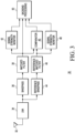
- FIG. 3 illustrates wireless receiver 30 in accordance with an embodiment.
- Wireless receiver 30 includes LNA 34, bandpass filter 36, matched filter 38, comparator 40, signal strength monitor 42, reference bandpass filter 44, reference matched filter 46, signal strength monitor 48, and backend processing block 50.
- Low-noise amplifier 34 has an input connected to antenna 32 for receiving a wireless transmission, and an output.
- Bandpass filter 36 has an input connected to the output of LNA 34, and an output.
- Matched filter 38 has an input connected to the output of bandpass filter 36, and an output.
- Reference bandpass filter 44 has an input connected to the output of LNA 34, and an output.
- Reference matched filter 46 has an input connected to the output of reference bandpass filter 44, and an output.
- Comparator 40 has a first input connected to the output of matched filter 38, a second input connected to the output of reference matched filter 46, and an output.
- Signal strength monitor 42 has an input connected to the output of matched filter 38, and an output.
- Signal strength monitor 48 has an input connected to the output of reference matched filter 46, and an output.
- Backend processing block 50 has a first input connected to the output of signal strength monitor 42, a second input connected to the output of matched filter 38, a third input connected to the output of comparator 40, and a fourth input connected to the output of signal strength monitor 48.
- Comparator 40 compares the signal energies at the outputs of matched filters 38 and 46. Because the frequencies outside of the allowed frequency band can also be in use by other radio frequency (RF) systems, it is required that measures be taken to prevent these other RF signals from disturbing the comparison of the signal energies. Therefore, the comparison only takes place during the time when a pulse is received by receiver 30. The time of the comparison is determined by when the pulse is processed by reference matched filter 46 because reference matched filter 46 has a higher bandwidth, and therefore outputs the pulse sooner than matched filter 38.
- RF radio frequency
- a result of the comparison by comparator 40 is that the energy at the output of matched filter 38 is substantially lower than the energy at the output of the reference matched filter 46, then a large amount of out-of-band energy has been received, indicating that the received signal comes from an illegitimate device, which is using a higher bandwidth in violation of the regulatory standard or protocol, to perform an attack.
- a difference of signal energies can be compared instead of an absolute value of signal energies.
- Transmit power is monitored using signal strength monitors 42 and 48 to detect violations of transmit power regulations, standards, or protocols. Monitoring transmit power addresses the case where an attacker uses higher transmit power than allowed, or uses a high-gain antenna to supersede the signal of the legitimate transmitter. In the case of the high-gain antenna, the parameter of a violated RF standard might not be transmit power, but of the field strength at a given distance. To make this determination, time-of-flight or triangulation of a plurality of receivers may be used, where each of the plurality of receivers measures a received signal level, calculates the transmitter's position, and thus its distance from the receivers. Alternately, a plurality of pulses from the wireless transmission may be received and a signal strength of the pulses may be averaged to determine if the transmission signal strength is within a transmit power specification value.
- the key fob may also be authenticated using a conventional authentication scheme to ensure that the key fob is legitimate.
- One way to authenticate is via challenge/response messages.
- the challenge/response communication may be any type of conventional challenge/response, such as a communication that uses a secret key and a cryptographic algorithm.
- the authentication process involves a common secret between the key fob and the vehicle. The vehicle will first transmit a challenge word to the key fob. Note that the challenge/response communication between the vehicle and the key fob requires the vehicle to also include a transmitter, which is not illustrated in FIG. 2 .
- the key fob calculates a response word based on the challenge word and on the common secret.
- the response word is transmitted to the vehicle.
- the vehicle knows from processing the response word if the key fob is in possession of the correct common secret. If the response word from the key fob is correct, the vehicle provides access. If the response word is incorrect, the vehicle does not provide access.
- another method for authentication may be used.
- Comparing the signal energies from the matched filter 38 and reference matched filter 46 provides the benefit of improving security by allowing a more informed compromise between the amount of out-of-band signal energy as discussed above regarding FIG. 2 . Furthermore, the described embodiment allows a better choice of bandpass bandwidth so that a distance bounding function is improved.
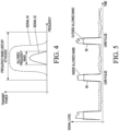
- FIG. 4 illustrates a signal characteristic comparison of a legitimate and illegitimate passband in the frequency domain.
- Signal 52 is from a legitimate transmitter and is shown within an allowed frequency band.
- Signal 54 is from an illegitimate transmitter and uses a much larger frequency band than legitimate signal 52. Also, signal 54 is transmitted with a much higher transmit power than signal 52, which can be detected using signal strength monitors 42 and 48 in FIG. 3 .
- FIG. 5 illustrates a signal characteristic comparison of a legitimate and illegitimate key fob pulse in the time domain. Two pulses are illustrated in FIG. 5 .
- Pulse 56 illustrates a UWB pulse that is within an allowed frequency band.
- Pulse 58 illustrates a UWB pulse that is outside of the allowed frequency band.
- the difference between a legitimate pulse and an illegitimate pulse may be difficult to detect and result in false alerts.
- a plurality of pulses from the wireless transmission may be received and a signal strength of the pulses may be averaged to determine if the transmission signal strength is within a transmit power specification value.
- the above described method to detect an illegitimate, or unauthorized key fob performs the detection using one or both of frequency bandwidth or signal strength.
- another predetermined parameter of a wireless transmission may be used.
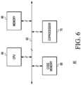
- FIG. 6 illustrates a simplified view of backend processing circuit 60 of the wireless receiver of FIG. 3 .
- Backend processing circuit 60 includes data and address bus 62.
- Each of central processing unit (CPU) 64, data memory 66, code memory 68, and coprocessor 70 are bi-directionally connected to bus 62.
- Backend processor 60 may be implemented on one or more integrated circuits.
- CPU 64 may be any hardware device capable of executing instructions stored in code memory 68.
- CPU 64 may be, for example, a microprocessor, field programmable gate array (FPGA), application-specific integrated circuit (ASIC), or similar device.
- FPGA field programmable gate array
- ASIC application-specific integrated circuit
- Data memory 66 may be any kind of memory, such as for example, L1, L2, or L3 cache or system memory.
- Data memory 66 may include volatile memory such as static random-access memory (SRAM) or dynamic RAM (DRAM), or may include non-volatile memory such as flash memory, read only memory (ROM), or other volatile or non-volatile memory.
- volatile memory such as static random-access memory (SRAM) or dynamic RAM (DRAM)
- non-volatile memory such as flash memory, read only memory (ROM), or other volatile or non-volatile memory.
- Code memory 68 may include one or more machine-readable storage media for storing instructions for execution by CPU 64. In other embodiments, memory 66 may also store data upon which CPU 64 may operate. Code memory 68 may store, for example, a machine learning model, or encryption, decryption, or verification applications. A software implementation of a rake receiver may be implemented in code memory 68. Code memory 68 may be implemented in a secure hardware element and be tamper-resistant.
- CPU 64 and coprocessor 70 may each be one or more of any kind of processor or processor core, such as for example, a microcontroller, microprocessor, digital signal processor, or the like, for executing instructions or commands.
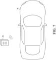
- FIG. 7 illustrates vehicle 74 and key fob transceiver 72.
- An automotive keyless entry system for vehicle 74 also includes key fob 72.
- Key fob 72 is a conventional key fob transceiver for communicating with the automobile keyless entry system for vehicle access.
- the vehicle 74 includes a keyless entry system that is based on a UWB protocol or standard for keyless entry systems.
- Vehicle 74 may be any kind of vehicle that can benefit from a keyless security system.
- Vehicle 74 may also be referred to as a car, automobile, truck, bus, or other type of vehicle that can benefit from the above described embodiments to detect if the key fob is legitimate or illegitimate.
- a method for detecting an attack on a keyless entry system for a vehicle includes receiving a wireless transmission by the keyless entry system.
- the wireless transmission is filtered in a first filter to produce a filtered wireless transmission.
- the wireless transmission is filtered in a second filter to produce a reference filtered wireless transmission.
- a frequency band of the filtered wireless transmission is compared to a frequency band of the reference filtered wireless transmission. Based on the comparison, it is determined if the wireless transmission is from a key fob that complies with the specification of the wireless transmission.
- a wireless receiver is provided for performing the method.
- Non-transitory machine-readable storage medium including any mechanism for storing information in a form readable by a machine, such as a personal computer, laptop computer, file server, smart phone, or other computing device.
- the non-transitory machine-readable storage medium may include volatile and non-volatile memories such as read only memory (ROM), random access memory (RAM), magnetic disk storage media, optical storage medium, NVM, and the like.
- ROM read only memory
- RAM random access memory
- magnetic disk storage media such as magnetic disks, optical storage medium, NVM, and the like.
- NVM non-transitory machine-readable storage medium excludes transitory signals.
Landscapes
- Engineering & Computer Science (AREA)
- Computer Security & Cryptography (AREA)
- Computer Networks & Wireless Communication (AREA)
- Signal Processing (AREA)
- Computer Hardware Design (AREA)
- Computing Systems (AREA)
- General Engineering & Computer Science (AREA)
- Physics & Mathematics (AREA)
- General Physics & Mathematics (AREA)
- Mechanical Engineering (AREA)
- Lock And Its Accessories (AREA)
Description
- This disclosure relates generally to security, and more particularly, to a wireless receiver and method for detecting an attack on a keyless entry system for a vehicle.
- Various security sensitive systems, such as contactless payment, contactless car access, contactless door access, etc. depend on wireless communications that may be subjected to attacks. Secure wireless transmissions, such as radio frequency (RF) transmissions, are mainly secured by one or both of distance bounding and cryptographic challenge/response mechanisms. However, there are several ways to attack these mechanisms to gain access to the security sensitive systems. For example, in an automotive security system protected by distance bounding, one known attack is called a relay attack. A relay attack may be mounted by two attackers, one near the legitimate key fob and the other near the car. In a successful relay attack the security system of the car is deceived about the actual distance between the legitimate key fob and the car by a relay channel set up between the legitimate key fob, the two attackers, and the car.
- Therefore, a need exists for a more secure method to protect security sensitive systems.
-
WO 2016/059451 A1 discloses a method for detecting relay attacks for a passive entry system, in which distance measurements are derived from signal strengths and time of arrival of low frequency transmissions from a key fob and compared to determine a mismatch. - According to the invention there is provided a method for detecting an attack on an ultra-wide band keyless entry system for a vehicle and a wireless receiver for an ultra-wide band keyless entry system in a vehicle, as defined in the accompanying claims.
- Disclosed herein is a method for detecting an attack on a wireless system, the method comprising: detecting a wireless transmission; comparing a predetermined parameter of the wireless transmission to a reference parameter; and determining if the wireless transmission is from a transmitter that complies with a specification of the wireless transmission based on the comparison.
- The predetermined parameter of the wireless transmission may be a frequency bandwidth and the reference parameter a frequency bandwidth specification value of a predetermined wireless transmission specification.
- The predetermined parameter of the wireless transmission may be a transmit power value and the reference parameter a predetermined transmit power specification value of a predetermined wireless transmission protocol specification.
- The method may further comprise measuring a signal strength of the wireless transmission to determine the transmit power value.
- Detecting the wireless transmission may further comprise: bandpass filtering the wireless transmission with a bandpass filter having a first predetermined passband; bandpass filtering the wireless transmission with a reference bandpass filter having a second predetermined passband; and filtering the bandpass filtered wireless transmission using a matched filter to produce a matched filter output; wherein comparing the predetermined parameter to the reference parameter further comprises comparing a signal strength of the matched filter output to a reference signal strength.
- The second predetermined passband may be larger than the first predetermined passband.
- The method may further comprise authenticating the wireless system if the wireless transmission is determined to comply with the specification.
- The predetermined parameter of the wireless transmission may be a transmit power value, and if the transmit power value of the wireless transmission is greater than a reference transmit power value, then the wireless transmission does not comply with the specification of the wireless transmission.
- The specification of the wireless transmission is an ultra-wide band (UWB) specification for a keyless entry system for a vehicle.
- The method may comprise receiving a plurality of pulses from the wireless transmission and averaging a signal strength of the plurality of pulses to determine if the transmission is within a transmit power specification value.
- Also disclosed herein is a method for detecting an attack on a keyless entry system for a vehicle, the method comprising: receiving a wireless transmission by the keyless entry system; filtering the wireless transmission in a first filter to produce a filtered wireless transmission; filtering the wireless transmission in a second filter to produce a reference filtered wireless transmission; comparing a frequency band of the filtered wireless transmission to a frequency band of the reference filtered wireless transmission; and determining if the wireless transmission is from a key fob that complies with the specification of the wireless transmission based on the comparison.
- The method may further comprise measuring a signal strength of the wireless transmission to determine the transmit power value.
- Filtering the wireless transmission in a first filter may further comprise: filtering a wireless transmission signal in a bandpass filter to produce a bandpass filtered wireless transmission signal; and filtering the bandpass filtered wireless transmission signal in a matched filter to produce the filtered wireless transmission signal.
- Filtering the wireless transmission in a second filter may further comprise: filtering a wireless transmission signal in a reference bandpass filter to produce a reference bandpass filtered wireless transmission signal; and filtering the reference bandpass filtered wireless transmission signal in a reference matched filter to produce the reference filtered wireless transmission signal.
- The method may further comprise authenticating the key fob if the wireless transmission is determined to comply with the specification.
- Also disclosed herein is a wireless receiver for a keyless entry system in a vehicle, the wireless receiver comprising: an amplifier having an input coupled to receive a wireless transmission from a key fob transceiver, and an output; a bandpass filter having an input coupled to the output of the amplifier, and an output; a matched filter having an input coupled to the output of the bandpass filter and an output; and a comparator having a first input coupled to the output of the matched filter, a second input coupled to receive a reference value, and an output for providing a result of a comparison of signal energies of the outputs of the matched filter and the reference matched filter.
- The wireless receiver may further comprise a signal strength monitor coupled to monitor a signal strength of the matched filter output.
- The wireless receiver may further comprise: a reference bandpass filter having an input coupled to the output of the amplifier, and an output; and a reference matched filter having an input coupled to the output of the bandpass filter, and output for providing the reference value.
- The comparator may determine if a bandwidth of the matched filter output matches a bandwidth of the reference value, and if the bandwidth of the matched filter output matches the bandwidth of the reference values, the wireless transmission complies with a wireless transmission protocol specification bandwidth.
- The wireless receiver may further comprise a first signal strength monitor coupled to receive the matched filter output and a second signal strength monitor coupled to receive the reference value, wherein a signal strength of the match filter output and a signal strength of the reference value are used to determine if the wireless transmission complies with the wireless transmission protocol.
- The present invention is illustrated by way of example and is not limited by the accompanying figures, in which like references indicate similar elements. Elements in the figures are illustrated for simplicity and clarity and have not necessarily been drawn to scale.
-
FIG. 1 illustrates a prior art wireless receiver. -
FIG. 2 illustrates a transfer characteristic of a bandpass filter of the wireless receiver ofFIG. 1 . -
FIG. 3 illustrates a wireless receiver in accordance with an embodiment. -
FIG. 4 illustrates a signal characteristic comparison of legitimate and illegitimate passbands in the frequency domain. -
FIG. 5 illustrates a signal characteristic comparison of a legitimate and illegitimate key fob pulse in the time domain. -
FIG. 6 illustrates a backend processing circuit of the wireless receiver ofFIG. 3 in accordance with an embodiment. -
FIG. 7 illustrates a vehicle and a key fob transceiver. - Generally, there is provided, a wireless system and a method for detecting attacks on the wireless system. The wireless system is a keyless entry system for a vehicle. The method includes detecting a wireless transmission, for example, from a key fob to a receiver of the wireless system. A predetermined parameter of the wireless transmission is compared to a reference parameter. Based on the comparison, it is then determined if the wireless transmission is from a transmitter that complies with a specification of the wireless transmission. The predetermined parameter may be a frequency bandwidth of the wireless transmission. The predetermined parameter may be a transmit power of the wireless transmission. The reference parameter is a specification value of the frequency bandwidth or transmit power of a transmission protocol or standard of the wireless transmissionThe predetermined parameter may be another specification value of the transmission protocol that can be measured in a receiver of a wireless transmission.
- The described method and receiver provides protection against relay attacks, while allowing out-of-frequency band content to be minimized.
- There is provided a method for detecting an attack on a wireless system, the method including: detecting a wireless transmission; comparing a predetermined parameter of the wireless transmission to a reference parameter; and determining if the wireless transmission is from a transmitter that complies with a specification of the wireless transmission based on the comparison. The predetermined parameter of the wireless transmission may be a frequency bandwidth and the reference parameter is a frequency bandwidth specification value of a predetermined wireless transmission specification. The predetermined parameter of the wireless transmission may be a transmit power value and the reference parameter may be a predetermined transmit power specification value of a predetermined wireless transmission protocol specification. The method may further include measuring a signal strength of the wireless transmission to determine the transmit power value. Detecting the wireless transmission may further include: bandpass filtering the wireless transmission with a bandpass filter having a first predetermined passband; bandpass filtering the wireless transmission with a reference bandpass filter having a second predetermined passband; and filtering the bandpass filtered wireless transmission using a matched filter to produce a matched filter output; wherein comparing the predetermined parameter to the reference parameter further comprises comparing a signal strength of the matched filter output to a reference signal strength. The second predetermined passband may be larger than the first predetermined passband. The method may further include authenticating the wireless system if the wireless transmission is determined to comply with the specification. The predetermined parameter of the wireless transmission may be a transmit power value, and if the transmit power value of the wireless transmission is greater than a reference transmit power value, then the wireless transmission does not comply with the specification of the wireless transmission. The specification of the wireless transmission may be an ultra-wide band (UWB) specification for a keyless entry system for a vehicle. Receiving a plurality of pulses from the wireless transmission and averaging a signal strength of the plurality of pulses may be performed to determine if the transmission is within a transmit power specification value.
- There is also provided a method for detecting an attack on a keyless entry system for a vehicle, the method including: receiving a wireless transmission by the keyless entry system; filtering the wireless transmission in a first filter to produce a filtered wireless transmission; filtering the wireless transmission in a second filter to produce a reference filtered wireless transmission; comparing a frequency band of the filtered wireless transmission to a frequency band of the reference filtered wireless transmission; and determining if the wireless transmission is from a key fob that complies with the specification of the wireless transmission based on the comparison. The method may further include measuring a signal strength of the wireless transmission to determine the transmit power value. Filtering the wireless transmission in a first filter may further include: filtering a wireless transmission signal in a bandpass filter to produce a bandpass filtered wireless transmission signal; and filtering the bandpass filtered wireless transmission signal in a matched filter to produce the filtered wireless transmission signal. Filtering the wireless transmission in a second filter may further include: filtering a wireless transmission signal in a reference bandpass filter to produce a reference bandpass filtered wireless transmission signal; and filtering the reference bandpass filtered wireless transmission signal in a reference matched filter to produce the reference filtered wireless transmission signal. The method may further include authenticating the key fob if the wireless transmission is determined to comply with the specification.
- There is also provided a wireless receiver for a keyless entry system in a vehicle, the wireless receiver including: an amplifier having an input coupled to receive a wireless transmission from a key fob transceiver, and an output; a bandpass filter having an input coupled to the output of the amplifier, and an output; a matched filter having an input coupled to the output of the bandpass filter and an output; and a comparator having a first input coupled to the output of the matched filter, a second input coupled to receive a reference value, and an output for providing a result of a comparison of signal energies of the outputs of the matched filter and the reference matched filter. The wireless receiver may further include a signal strength monitor coupled to monitor a signal strength of the matched filter output. The wireless receiver may further include: a reference bandpass filter having an input coupled to the output of the amplifier, and an output; and a reference matched filter having an input coupled to the output of the bandpass filter, and output for providing the reference value. The comparator may determine if a bandwidth of the matched filter output matches a bandwidth of the reference value, and if the bandwidth of the matched filter output matches the bandwidth of the reference values, the wireless transmission complies with a wireless transmission protocol specification bandwidth. The wireless receiver may further include a first signal strength monitor coupled to receive the matched filter output and a second signal strength monitor coupled to receive the reference value, wherein a signal strength of the match filter output and a signal strength of the reference value are used to determine if the wireless transmission complies with the wireless transmission protocol.
-
FIG. 1 illustrates a priorart wireless receiver 10.Wireless receiver 10 includes low noise amplifier (LNA) 14,bandpass filter 16, matchedfilter 18, andbackend 20.Amplifier 14 has an input connected toantenna 12, and an output.Amplifier 14 receives a wireless transmission fromantenna 12.Bandpass filter 16 has an input connected to the output ofLNA 14, and an output for providing a bandpass filtered signal. Matchedfilter 18 has an input connected to the output ofbandpass filter 16, and an output for providing a matched filtered output signal.Backend 20 is connected to receive the matched filtered output signal from matchedfilter 18.Backend 20 may include signal processor, data processor, and related systems. An example processor for use inbackend 20 is illustrated inFIG. 6 and will be described later.Receiver 10 may be an ultra-wide band (UWB) receiver. Inreceiver 10, a signal is received fromantenna 12 and amplified inLNA 14. The relevant frequency band is filtered out bybandpass filter 16. A pulse shape of the signal used for distance bounding is known and hence may be passed through matchedfilter 18 to achieve a better signal-to-noise ratio (SNR). The output of matchedfilter 18 is provided tobackend 20 for further processing. -
FIG. 2 illustrates a graph of atransfer characteristic 22 ofbandpass filter 16 ofwireless receiver 10 ofFIG. 1 . An allowed frequency band ofbandpass filter 16 is illustrated inFIG. 2 and labeled "FREQUENCY BAND." Ideally,bandpass filter 16 should not attenuate signal frequencies inside the allowed frequency band, and completely block all other frequencies. The frequency blocking provided bybandpass filter 16 is important to reduce noise and other signals outside the allowed frequency band. An area labeled "A" inFIG.2 shows unintended attenuation for the allowed signal frequencies, while an area labeled "B" shows the unintended passing thru of frequencies outside of the allowed frequency band. For a UWB bandpass filter, the frequencies would be at least in the upper Megahertz range.Bandpass filter 16 is an analog filter, so that the edges of the filter transfer characteristic cannot be made so steep that areas A and B are negligibly small. By changing the upper and lower cut-off frequencies ofbandpass filter 16, area A can be reduced, but area B will become larger, which will cause more noise to be received and reduce the SNR, requiring more transmit power. However, increasing the transmit power may not be allowed if the maximum transmit power is being used. Conversely, if the area B is reduced, area A will become larger, which will lead to lost signal content, and reduce the accuracy of distance bounding. Hence, there is a trade-off between minimizing the unwanted areas A and B. - Because the accuracy of distance bounding is directly linked to the security against attacks, reducing area A in
FIG. 2 is a primary goal, and therefore the increased area of area B has generally been accepted. However, increasing the area of area B will result inreceiver 10 being more vulnerable to attacks from illegitimate devices. -
FIG. 3 illustrateswireless receiver 30 in accordance with an embodiment.Wireless receiver 30 includesLNA 34,bandpass filter 36, matchedfilter 38,comparator 40, signalstrength monitor 42,reference bandpass filter 44, reference matchedfilter 46, signalstrength monitor 48, andbackend processing block 50. Low-noise amplifier 34 has an input connected toantenna 32 for receiving a wireless transmission, and an output.Bandpass filter 36 has an input connected to the output ofLNA 34, and an output. Matchedfilter 38 has an input connected to the output ofbandpass filter 36, and an output.Reference bandpass filter 44 has an input connected to the output ofLNA 34, and an output. Reference matchedfilter 46 has an input connected to the output ofreference bandpass filter 44, and an output.Comparator 40 has a first input connected to the output of matchedfilter 38, a second input connected to the output of reference matchedfilter 46, and an output. Signal strength monitor 42 has an input connected to the output of matchedfilter 38, and an output. Signal strength monitor 48 has an input connected to the output of reference matchedfilter 46, and an output.Backend processing block 50 has a first input connected to the output ofsignal strength monitor 42, a second input connected to the output of matchedfilter 38, a third input connected to the output ofcomparator 40, and a fourth input connected to the output ofsignal strength monitor 48. -
Comparator 40 compares the signal energies at the outputs of matchedfilters receiver 30. The time of the comparison is determined by when the pulse is processed by reference matchedfilter 46 because reference matchedfilter 46 has a higher bandwidth, and therefore outputs the pulse sooner than matchedfilter 38. If a result of the comparison bycomparator 40 is that the energy at the output of matchedfilter 38 is substantially lower than the energy at the output of the reference matchedfilter 46, then a large amount of out-of-band energy has been received, indicating that the received signal comes from an illegitimate device, which is using a higher bandwidth in violation of the regulatory standard or protocol, to perform an attack. To reduce the influence of signal frequencies outside of the allowed band, a difference of signal energies can be compared instead of an absolute value of signal energies. - Transmit power is monitored using signal strength monitors 42 and 48 to detect violations of transmit power regulations, standards, or protocols. Monitoring transmit power addresses the case where an attacker uses higher transmit power than allowed, or uses a high-gain antenna to supersede the signal of the legitimate transmitter. In the case of the high-gain antenna, the parameter of a violated RF standard might not be transmit power, but of the field strength at a given distance. To make this determination, time-of-flight or triangulation of a plurality of receivers may be used, where each of the plurality of receivers measures a received signal level, calculates the transmitter's position, and thus its distance from the receivers. Alternately, a plurality of pulses from the wireless transmission may be received and a signal strength of the pulses may be averaged to determine if the transmission signal strength is within a transmit power specification value.
- After it is determined that the wireless transmission complies with a specification protocol, the key fob may also be authenticated using a conventional authentication scheme to ensure that the key fob is legitimate. One way to authenticate is via challenge/response messages. The challenge/response communication may be any type of conventional challenge/response, such as a communication that uses a secret key and a cryptographic algorithm. For example, in one embodiment, the authentication process involves a common secret between the key fob and the vehicle. The vehicle will first transmit a challenge word to the key fob. Note that the challenge/response communication between the vehicle and the key fob requires the vehicle to also include a transmitter, which is not illustrated in
FIG. 2 . The key fob calculates a response word based on the challenge word and on the common secret. The response word is transmitted to the vehicle. The vehicle knows from processing the response word if the key fob is in possession of the correct common secret. If the response word from the key fob is correct, the vehicle provides access. If the response word is incorrect, the vehicle does not provide access. In another embodiment, another method for authentication may be used. - Comparing the signal energies from the matched
filter 38 and reference matchedfilter 46 provides the benefit of improving security by allowing a more informed compromise between the amount of out-of-band signal energy as discussed above regardingFIG. 2 . Furthermore, the described embodiment allows a better choice of bandpass bandwidth so that a distance bounding function is improved. -
FIG. 4 illustrates a signal characteristic comparison of a legitimate and illegitimate passband in the frequency domain.Signal 52 is from a legitimate transmitter and is shown within an allowed frequency band.Signal 54 is from an illegitimate transmitter and uses a much larger frequency band thanlegitimate signal 52. Also, signal 54 is transmitted with a much higher transmit power thansignal 52, which can be detected using signal strength monitors 42 and 48 inFIG. 3 . -
FIG. 5 illustrates a signal characteristic comparison of a legitimate and illegitimate key fob pulse in the time domain. Two pulses are illustrated inFIG. 5 .Pulse 56 illustrates a UWB pulse that is within an allowed frequency band.Pulse 58 illustrates a UWB pulse that is outside of the allowed frequency band. As can be seen inFIG. 5 , the difference between a legitimate pulse and an illegitimate pulse may be difficult to detect and result in false alerts. To improve detection accuracy, a plurality of pulses from the wireless transmission may be received and a signal strength of the pulses may be averaged to determine if the transmission signal strength is within a transmit power specification value. - The above described method to detect an illegitimate, or unauthorized key fob performs the detection using one or both of frequency bandwidth or signal strength. In other embodiments, another predetermined parameter of a wireless transmission may be used.
-
FIG. 6 illustrates a simplified view ofbackend processing circuit 60 of the wireless receiver ofFIG. 3 .Backend processing circuit 60 includes data andaddress bus 62. Each of central processing unit (CPU) 64,data memory 66,code memory 68, andcoprocessor 70 are bi-directionally connected tobus 62.Backend processor 60 may be implemented on one or more integrated circuits.CPU 64 may be any hardware device capable of executing instructions stored incode memory 68.CPU 64 may be, for example, a microprocessor, field programmable gate array (FPGA), application-specific integrated circuit (ASIC), or similar device. -
Data memory 66 may be any kind of memory, such as for example, L1, L2, or L3 cache or system memory.Data memory 66 may include volatile memory such as static random-access memory (SRAM) or dynamic RAM (DRAM), or may include non-volatile memory such as flash memory, read only memory (ROM), or other volatile or non-volatile memory. -
Code memory 68 may include one or more machine-readable storage media for storing instructions for execution byCPU 64. In other embodiments,memory 66 may also store data upon whichCPU 64 may operate.Code memory 68 may store, for example, a machine learning model, or encryption, decryption, or verification applications. A software implementation of a rake receiver may be implemented incode memory 68.Code memory 68 may be implemented in a secure hardware element and be tamper-resistant. -
CPU 64 andcoprocessor 70 may each be one or more of any kind of processor or processor core, such as for example, a microcontroller, microprocessor, digital signal processor, or the like, for executing instructions or commands. -
FIG. 7 illustratesvehicle 74 andkey fob transceiver 72. An automotive keyless entry system forvehicle 74 also includeskey fob 72.Key fob 72 is a conventional key fob transceiver for communicating with the automobile keyless entry system for vehicle access. Thevehicle 74 includes a keyless entry system that is based on a UWB protocol or standard for keyless entry systems.Vehicle 74 may be any kind of vehicle that can benefit from a keyless security system.Vehicle 74 may also be referred to as a car, automobile, truck, bus, or other type of vehicle that can benefit from the above described embodiments to detect if the key fob is legitimate or illegitimate. - A method is provided for detecting an attack on a keyless entry system for a vehicle. The method includes receiving a wireless transmission by the keyless entry system. The wireless transmission is filtered in a first filter to produce a filtered wireless transmission. The wireless transmission is filtered in a second filter to produce a reference filtered wireless transmission. A frequency band of the filtered wireless transmission is compared to a frequency band of the reference filtered wireless transmission. Based on the comparison, it is determined if the wireless transmission is from a key fob that complies with the specification of the wireless transmission. In another embodiment, a wireless receiver is provided for performing the method.
- Various embodiments, or portions of the embodiments, may be implemented in hardware or as instructions on a non-transitory machine-readable storage medium including any mechanism for storing information in a form readable by a machine, such as a personal computer, laptop computer, file server, smart phone, or other computing device. The non-transitory machine-readable storage medium may include volatile and non-volatile memories such as read only memory (ROM), random access memory (RAM), magnetic disk storage media, optical storage medium, NVM, and the like. The non-transitory machine-readable storage medium excludes transitory signals.
- Although the invention is described herein with reference to specific embodiments, various modifications and changes can be made without departing from the scope of the present invention as set forth in the claims below. Accordingly, the specification and figures are to be regarded in an illustrative rather than a restrictive sense, and all such modifications are intended to be included within the scope of the present invention. Any benefits, advantages, or solutions to problems that are described herein with regard to specific embodiments are not intended to be construed as a critical, required, or essential feature or element of any or all the claims.
- Furthermore, the terms "a" or "an," as used herein, are defined as one or more than one. Also, the use of introductory phrases such as "at least one" and "one or more" in the claims should not be construed to imply that the introduction of another claim element by the indefinite articles "a" or "an" limits any particular claim containing such introduced claim element to inventions containing only one such element, even when the same claim includes the introductory phrases "one or more" or "at least one" and indefinite articles such as "a" or "an." The same holds true for the use of definite articles.
- Unless stated otherwise, terms such as "first" and "second" are used to arbitrarily distinguish between the elements such terms describe. Thus, these terms are not necessarily intended to indicate temporal or other prioritization of such elements.
Claims (6)
- A method for detecting an attack on an ultra-wide band, UWB, keyless entry system for a vehicle by a wireless receiver in the vehicle, the method comprising:detecting a wireless transmission;bandpass filtering the wireless transmission with a bandpass filter (36) and a matched filter (38) having a first predetermined passband to produce a first filter output;bandpass filtering the wireless transmission with a reference bandpass filter (44) and a reference matched filter (46) having a second predetermined passband larger than the first predetermined passband to produce a second filter output;comparing a signal energy of the first filter output to a signal energy of the second filter output; anddetermining that the wireless transmission is from an illegitimate device if the signal energy of the first filter output is substantially lower than the signal energy of the second filter output.
- The method of claim 1, further comprising authenticating the wireless system if the signal strength of the second filter output is not higher than the signal strength of the first filter output.
- The method of any preceding claim, wherein the wireless transmission comprises a plurality of pulses and comparing a signal strength comprises averaging a signal strength of the plurality of pulses.
- A wireless receiver (30) for an ultra-wide band, UWB, keyless entry system in a vehicle, the wireless receiver (30) comprising:an amplifier (34) having an input coupled to receive a wireless transmission from a key fob transceiver, and an output;a bandpass filter (36) having an input coupled to the output of the amplifier (34), and an output;a matched filter (38) having an input coupled to the output of the bandpass filter (36) and an output, the bandpass filter and matched filter having a first predetermined passband;a reference bandpass filter (44) having an input coupled to the output of the amplifier (34), and an output; anda reference matched filter (46) having an input coupled to the output of the reference bandpass filter (44), and an output for providing a reference value, the reference bandpass filter and reference matched filter having a second predetermined passband larger than the first predetermined passband;a comparator (40) having a first input coupled to the output of the matched filter (38), a second input coupled to receive the reference value, and an output for providing a result of a comparison of signal energies of the outputs of the matched filter (38) and the reference matched filter (46); anda backend processor (50) configured to determine that the wireless transmission is from an illegitimate device if the output from the comparator (40) indicates that the signal energy from the matched filter (38) is substantially lower than the signal energy from the reference matched filter (46).
- The wireless receiver (30) of claim 4, further comprising a signal strength monitor (42) coupled to monitor a signal strength of the matched filter output.
- The wireless receiver of claim 4, further comprising a first signal strength monitor (42) coupled to receive the matched filter output and a second signal strength monitor (48) coupled to receive the reference value, wherein a signal strength of the matched filter output and a signal strength of the reference value are used to determine if the wireless transmission complies with a wireless transmission protocol.
Applications Claiming Priority (1)
| Application Number | Priority Date | Filing Date | Title |
|---|---|---|---|
| US16/051,558 US10629011B2 (en) | 2018-08-01 | 2018-08-01 | Wireless receiver and method for detecting an attack on a keyless entry system for a vehicle |
Publications (2)
| Publication Number | Publication Date |
|---|---|
| EP3605476A1 EP3605476A1 (en) | 2020-02-05 |
| EP3605476B1 true EP3605476B1 (en) | 2023-06-07 |
Family
ID=67438385
Family Applications (1)
| Application Number | Title | Priority Date | Filing Date |
|---|---|---|---|
| EP19187580.6A Active EP3605476B1 (en) | 2018-08-01 | 2019-07-22 | Wireless receiver and method for detecting an attack on a keyless entry system for a vehicle |
Country Status (2)
| Country | Link |
|---|---|
| US (1) | US10629011B2 (en) |
| EP (1) | EP3605476B1 (en) |
Families Citing this family (2)
| Publication number | Priority date | Publication date | Assignee | Title |
|---|---|---|---|---|
| JP6653986B1 (en) * | 2019-12-06 | 2020-02-26 | マレリ株式会社 | Relay attack judgment device |
| FR3113738B1 (en) * | 2020-09-01 | 2022-07-29 | Continental Automotive | Method for activating a function of a vehicle by ultra wide band with portable user equipment, system and device for activating an associated function |
Family Cites Families (5)
| Publication number | Priority date | Publication date | Assignee | Title |
|---|---|---|---|---|
| JP4676316B2 (en) * | 2005-11-18 | 2011-04-27 | ルネサスエレクトロニクス株式会社 | Reception device, communication device, and control device using the same |
| US8930045B2 (en) * | 2013-05-01 | 2015-01-06 | Delphi Technologies, Inc. | Relay attack prevention for passive entry passive start (PEPS) vehicle security systems |
| WO2016059451A1 (en) | 2014-10-15 | 2016-04-21 | Continental Automotive Gmbh | Method and system for detecting relay attack for pase system |
| US9775034B2 (en) * | 2015-02-06 | 2017-09-26 | Nxp B.V. | Communications with distance authentication |
| US10532719B2 (en) * | 2016-12-30 | 2020-01-14 | Robert Bosch Gmbh | Bluetooth low energy (BLE) passive vehicle access control system for defending the system against relay attacks and method thereof |
-
2018
- 2018-08-01 US US16/051,558 patent/US10629011B2/en active Active
-
2019
- 2019-07-22 EP EP19187580.6A patent/EP3605476B1/en active Active
Also Published As
| Publication number | Publication date |
|---|---|
| US20200043265A1 (en) | 2020-02-06 |
| EP3605476A1 (en) | 2020-02-05 |
| US10629011B2 (en) | 2020-04-21 |
Similar Documents
| Publication | Publication Date | Title |
|---|---|---|
| US8698605B2 (en) | Determining the validity of a connection between a reader and a transponder | |
| US10044512B2 (en) | Decoupling of measuring the response time of a transponder and its authentication | |
| US11611876B2 (en) | Authentication system and authentication method | |
| US10766453B2 (en) | Apparatus, key remote, and method for controlling operating conditions of a key module | |
| EP3599781B1 (en) | Method for protecting a passive keyless entry system against a relay attack | |
| US9558607B2 (en) | Relay attack prevention using RSSIPPLX | |
| US20140169193A1 (en) | Relay attack prevention | |
| US20160350987A1 (en) | Communications with interaction detection | |
| KR102499447B1 (en) | Method for detecting relay attack, device for detecting relay attack, and computer program | |
| EP3605476B1 (en) | Wireless receiver and method for detecting an attack on a keyless entry system for a vehicle | |
| KR102246430B1 (en) | How to protect against relay attack | |
| US10389751B2 (en) | Wireless data security between vehicle components | |
| JP2018523390A (en) | System for device authentication | |
| JP2021188924A (en) | Control device and program | |
| JP3722216B2 (en) | Transfer detection method during data transmission | |
| KR102515940B1 (en) | Method for detecting jitter attack, apparatus for detecting jitter attack, and computer program | |
| JP6835982B2 (en) | How to temporarily prohibit remote activation of functions provided in automatic vehicles | |
| JP5429195B2 (en) | Electronic key system | |
| US11427160B2 (en) | Field superposition method and system | |
| WO2017131113A1 (en) | System for determining correctness of wireless communication | |
| KR20240158023A (en) | Providing Method for Enhanced Security of a vehicle, computing system and vehicle supporting the same | |
| HK1151910A (en) | Decoupling of measuring the response time of a transponder and its authentication |
Legal Events
| Date | Code | Title | Description |
|---|---|---|---|
| PUAI | Public reference made under article 153(3) epc to a published international application that has entered the european phase |
Free format text: ORIGINAL CODE: 0009012 |
|
| STAA | Information on the status of an ep patent application or granted ep patent |
Free format text: STATUS: THE APPLICATION HAS BEEN PUBLISHED |
|
| AK | Designated contracting states |
Kind code of ref document: A1 Designated state(s): AL AT BE BG CH CY CZ DE DK EE ES FI FR GB GR HR HU IE IS IT LI LT LU LV MC MK MT NL NO PL PT RO RS SE SI SK SM TR |
|
| AX | Request for extension of the european patent |
Extension state: BA ME |
|
| STAA | Information on the status of an ep patent application or granted ep patent |
Free format text: STATUS: REQUEST FOR EXAMINATION WAS MADE |
|
| 17P | Request for examination filed |
Effective date: 20200805 |
|
| RBV | Designated contracting states (corrected) |
Designated state(s): AL AT BE BG CH CY CZ DE DK EE ES FI FR GB GR HR HU IE IS IT LI LT LU LV MC MK MT NL NO PL PT RO RS SE SI SK SM TR |
|
| RIC1 | Information provided on ipc code assigned before grant |
Ipc: B60R 25/00 20130101ALN20221111BHEP Ipc: G07C 9/00 20200101AFI20221111BHEP |
|
| GRAP | Despatch of communication of intention to grant a patent |
Free format text: ORIGINAL CODE: EPIDOSNIGR1 |
|
| STAA | Information on the status of an ep patent application or granted ep patent |
Free format text: STATUS: GRANT OF PATENT IS INTENDED |
|
| INTG | Intention to grant announced |
Effective date: 20230118 |
|
| GRAS | Grant fee paid |
Free format text: ORIGINAL CODE: EPIDOSNIGR3 |
|
| GRAA | (expected) grant |
Free format text: ORIGINAL CODE: 0009210 |
|
| STAA | Information on the status of an ep patent application or granted ep patent |
Free format text: STATUS: THE PATENT HAS BEEN GRANTED |
|
| AK | Designated contracting states |
Kind code of ref document: B1 Designated state(s): AL AT BE BG CH CY CZ DE DK EE ES FI FR GB GR HR HU IE IS IT LI LT LU LV MC MK MT NL NO PL PT RO RS SE SI SK SM TR |
|
| REG | Reference to a national code |
Ref country code: GB Ref legal event code: FG4D |
|
| REG | Reference to a national code |
Ref country code: CH Ref legal event code: EP Ref country code: AT Ref legal event code: REF Ref document number: 1577312 Country of ref document: AT Kind code of ref document: T Effective date: 20230615 Ref country code: DE Ref legal event code: R096 Ref document number: 602019029823 Country of ref document: DE |
|
| REG | Reference to a national code |
Ref country code: LT Ref legal event code: MG9D |
|
| REG | Reference to a national code |
Ref country code: NL Ref legal event code: MP Effective date: 20230607 |
|
| P01 | Opt-out of the competence of the unified patent court (upc) registered |
Effective date: 20230907 |
|
| PG25 | Lapsed in a contracting state [announced via postgrant information from national office to epo] |
Ref country code: SE Free format text: LAPSE BECAUSE OF FAILURE TO SUBMIT A TRANSLATION OF THE DESCRIPTION OR TO PAY THE FEE WITHIN THE PRESCRIBED TIME-LIMIT Effective date: 20230607 Ref country code: NO Free format text: LAPSE BECAUSE OF FAILURE TO SUBMIT A TRANSLATION OF THE DESCRIPTION OR TO PAY THE FEE WITHIN THE PRESCRIBED TIME-LIMIT Effective date: 20230907 Ref country code: ES Free format text: LAPSE BECAUSE OF FAILURE TO SUBMIT A TRANSLATION OF THE DESCRIPTION OR TO PAY THE FEE WITHIN THE PRESCRIBED TIME-LIMIT Effective date: 20230607 |
|
| REG | Reference to a national code |
Ref country code: AT Ref legal event code: MK05 Ref document number: 1577312 Country of ref document: AT Kind code of ref document: T Effective date: 20230607 |
|
| PG25 | Lapsed in a contracting state [announced via postgrant information from national office to epo] |
Ref country code: RS Free format text: LAPSE BECAUSE OF FAILURE TO SUBMIT A TRANSLATION OF THE DESCRIPTION OR TO PAY THE FEE WITHIN THE PRESCRIBED TIME-LIMIT Effective date: 20230607 Ref country code: NL Free format text: LAPSE BECAUSE OF FAILURE TO SUBMIT A TRANSLATION OF THE DESCRIPTION OR TO PAY THE FEE WITHIN THE PRESCRIBED TIME-LIMIT Effective date: 20230607 Ref country code: LV Free format text: LAPSE BECAUSE OF FAILURE TO SUBMIT A TRANSLATION OF THE DESCRIPTION OR TO PAY THE FEE WITHIN THE PRESCRIBED TIME-LIMIT Effective date: 20230607 Ref country code: LT Free format text: LAPSE BECAUSE OF FAILURE TO SUBMIT A TRANSLATION OF THE DESCRIPTION OR TO PAY THE FEE WITHIN THE PRESCRIBED TIME-LIMIT Effective date: 20230607 Ref country code: HR Free format text: LAPSE BECAUSE OF FAILURE TO SUBMIT A TRANSLATION OF THE DESCRIPTION OR TO PAY THE FEE WITHIN THE PRESCRIBED TIME-LIMIT Effective date: 20230607 Ref country code: GR Free format text: LAPSE BECAUSE OF FAILURE TO SUBMIT A TRANSLATION OF THE DESCRIPTION OR TO PAY THE FEE WITHIN THE PRESCRIBED TIME-LIMIT Effective date: 20230908 |
|
| PGFP | Annual fee paid to national office [announced via postgrant information from national office to epo] |
Ref country code: FR Payment date: 20230720 Year of fee payment: 5 Ref country code: DE Payment date: 20230620 Year of fee payment: 5 |
|
| PG25 | Lapsed in a contracting state [announced via postgrant information from national office to epo] |
Ref country code: FI Free format text: LAPSE BECAUSE OF FAILURE TO SUBMIT A TRANSLATION OF THE DESCRIPTION OR TO PAY THE FEE WITHIN THE PRESCRIBED TIME-LIMIT Effective date: 20230607 |
|
| PG25 | Lapsed in a contracting state [announced via postgrant information from national office to epo] |
Ref country code: SK Free format text: LAPSE BECAUSE OF FAILURE TO SUBMIT A TRANSLATION OF THE DESCRIPTION OR TO PAY THE FEE WITHIN THE PRESCRIBED TIME-LIMIT Effective date: 20230607 |
|
| PG25 | Lapsed in a contracting state [announced via postgrant information from national office to epo] |
Ref country code: IS Free format text: LAPSE BECAUSE OF FAILURE TO SUBMIT A TRANSLATION OF THE DESCRIPTION OR TO PAY THE FEE WITHIN THE PRESCRIBED TIME-LIMIT Effective date: 20231007 |
|
| PG25 | Lapsed in a contracting state [announced via postgrant information from national office to epo] |
Ref country code: SM Free format text: LAPSE BECAUSE OF FAILURE TO SUBMIT A TRANSLATION OF THE DESCRIPTION OR TO PAY THE FEE WITHIN THE PRESCRIBED TIME-LIMIT Effective date: 20230607 Ref country code: SK Free format text: LAPSE BECAUSE OF FAILURE TO SUBMIT A TRANSLATION OF THE DESCRIPTION OR TO PAY THE FEE WITHIN THE PRESCRIBED TIME-LIMIT Effective date: 20230607 Ref country code: RO Free format text: LAPSE BECAUSE OF FAILURE TO SUBMIT A TRANSLATION OF THE DESCRIPTION OR TO PAY THE FEE WITHIN THE PRESCRIBED TIME-LIMIT Effective date: 20230607 Ref country code: PT Free format text: LAPSE BECAUSE OF FAILURE TO SUBMIT A TRANSLATION OF THE DESCRIPTION OR TO PAY THE FEE WITHIN THE PRESCRIBED TIME-LIMIT Effective date: 20231009 Ref country code: IS Free format text: LAPSE BECAUSE OF FAILURE TO SUBMIT A TRANSLATION OF THE DESCRIPTION OR TO PAY THE FEE WITHIN THE PRESCRIBED TIME-LIMIT Effective date: 20231007 Ref country code: EE Free format text: LAPSE BECAUSE OF FAILURE TO SUBMIT A TRANSLATION OF THE DESCRIPTION OR TO PAY THE FEE WITHIN THE PRESCRIBED TIME-LIMIT Effective date: 20230607 Ref country code: CZ Free format text: LAPSE BECAUSE OF FAILURE TO SUBMIT A TRANSLATION OF THE DESCRIPTION OR TO PAY THE FEE WITHIN THE PRESCRIBED TIME-LIMIT Effective date: 20230607 Ref country code: AT Free format text: LAPSE BECAUSE OF FAILURE TO SUBMIT A TRANSLATION OF THE DESCRIPTION OR TO PAY THE FEE WITHIN THE PRESCRIBED TIME-LIMIT Effective date: 20230607 |
|
| PG25 | Lapsed in a contracting state [announced via postgrant information from national office to epo] |
Ref country code: PL Free format text: LAPSE BECAUSE OF FAILURE TO SUBMIT A TRANSLATION OF THE DESCRIPTION OR TO PAY THE FEE WITHIN THE PRESCRIBED TIME-LIMIT Effective date: 20230607 |
|
| REG | Reference to a national code |
Ref country code: CH Ref legal event code: PL |
|
| REG | Reference to a national code |
Ref country code: DE Ref legal event code: R097 Ref document number: 602019029823 Country of ref document: DE |
|
| PG25 | Lapsed in a contracting state [announced via postgrant information from national office to epo] |
Ref country code: MC Free format text: LAPSE BECAUSE OF FAILURE TO SUBMIT A TRANSLATION OF THE DESCRIPTION OR TO PAY THE FEE WITHIN THE PRESCRIBED TIME-LIMIT Effective date: 20230607 |
|
| REG | Reference to a national code |
Ref country code: BE Ref legal event code: MM Effective date: 20230731 |
|
| PG25 | Lapsed in a contracting state [announced via postgrant information from national office to epo] |
Ref country code: LU Free format text: LAPSE BECAUSE OF NON-PAYMENT OF DUE FEES Effective date: 20230722 |
|
| PG25 | Lapsed in a contracting state [announced via postgrant information from national office to epo] |
Ref country code: MC Free format text: LAPSE BECAUSE OF FAILURE TO SUBMIT A TRANSLATION OF THE DESCRIPTION OR TO PAY THE FEE WITHIN THE PRESCRIBED TIME-LIMIT Effective date: 20230607 Ref country code: LU Free format text: LAPSE BECAUSE OF NON-PAYMENT OF DUE FEES Effective date: 20230722 |
|
| PLBE | No opposition filed within time limit |
Free format text: ORIGINAL CODE: 0009261 |
|
| STAA | Information on the status of an ep patent application or granted ep patent |
Free format text: STATUS: NO OPPOSITION FILED WITHIN TIME LIMIT |
|
| REG | Reference to a national code |
Ref country code: IE Ref legal event code: MM4A |
|
| PG25 | Lapsed in a contracting state [announced via postgrant information from national office to epo] |
Ref country code: DK Free format text: LAPSE BECAUSE OF FAILURE TO SUBMIT A TRANSLATION OF THE DESCRIPTION OR TO PAY THE FEE WITHIN THE PRESCRIBED TIME-LIMIT Effective date: 20230607 Ref country code: CH Free format text: LAPSE BECAUSE OF NON-PAYMENT OF DUE FEES Effective date: 20230731 |
|
| PG25 | Lapsed in a contracting state [announced via postgrant information from national office to epo] |
Ref country code: SI Free format text: LAPSE BECAUSE OF FAILURE TO SUBMIT A TRANSLATION OF THE DESCRIPTION OR TO PAY THE FEE WITHIN THE PRESCRIBED TIME-LIMIT Effective date: 20230607 |
|
| 26N | No opposition filed |
Effective date: 20240308 |
|
| GBPC | Gb: european patent ceased through non-payment of renewal fee |
Effective date: 20230907 |
|
| PG25 | Lapsed in a contracting state [announced via postgrant information from national office to epo] |
Ref country code: SI Free format text: LAPSE BECAUSE OF FAILURE TO SUBMIT A TRANSLATION OF THE DESCRIPTION OR TO PAY THE FEE WITHIN THE PRESCRIBED TIME-LIMIT Effective date: 20230607 Ref country code: IT Free format text: LAPSE BECAUSE OF FAILURE TO SUBMIT A TRANSLATION OF THE DESCRIPTION OR TO PAY THE FEE WITHIN THE PRESCRIBED TIME-LIMIT Effective date: 20230607 Ref country code: BE Free format text: LAPSE BECAUSE OF NON-PAYMENT OF DUE FEES Effective date: 20230731 |
|
| PG25 | Lapsed in a contracting state [announced via postgrant information from national office to epo] |
Ref country code: IE Free format text: LAPSE BECAUSE OF NON-PAYMENT OF DUE FEES Effective date: 20230722 |
|
| PG25 | Lapsed in a contracting state [announced via postgrant information from national office to epo] |
Ref country code: GB Free format text: LAPSE BECAUSE OF NON-PAYMENT OF DUE FEES Effective date: 20230907 |
|
| PG25 | Lapsed in a contracting state [announced via postgrant information from national office to epo] |
Ref country code: IE Free format text: LAPSE BECAUSE OF NON-PAYMENT OF DUE FEES Effective date: 20230722 Ref country code: GB Free format text: LAPSE BECAUSE OF NON-PAYMENT OF DUE FEES Effective date: 20230907 |
|
| PG25 | Lapsed in a contracting state [announced via postgrant information from national office to epo] |
Ref country code: BG Free format text: LAPSE BECAUSE OF FAILURE TO SUBMIT A TRANSLATION OF THE DESCRIPTION OR TO PAY THE FEE WITHIN THE PRESCRIBED TIME-LIMIT Effective date: 20230607 |
|
| PG25 | Lapsed in a contracting state [announced via postgrant information from national office to epo] |
Ref country code: BG Free format text: LAPSE BECAUSE OF FAILURE TO SUBMIT A TRANSLATION OF THE DESCRIPTION OR TO PAY THE FEE WITHIN THE PRESCRIBED TIME-LIMIT Effective date: 20230607 |
|
| REG | Reference to a national code |
Ref country code: DE Ref legal event code: R119 Ref document number: 602019029823 Country of ref document: DE |
|
| PG25 | Lapsed in a contracting state [announced via postgrant information from national office to epo] |
Ref country code: DE Free format text: LAPSE BECAUSE OF NON-PAYMENT OF DUE FEES Effective date: 20250201 |
|
| PG25 | Lapsed in a contracting state [announced via postgrant information from national office to epo] |
Ref country code: FR Free format text: LAPSE BECAUSE OF NON-PAYMENT OF DUE FEES Effective date: 20240731 |
|
| PG25 | Lapsed in a contracting state [announced via postgrant information from national office to epo] |
Ref country code: CY Free format text: LAPSE BECAUSE OF FAILURE TO SUBMIT A TRANSLATION OF THE DESCRIPTION OR TO PAY THE FEE WITHIN THE PRESCRIBED TIME-LIMIT; INVALID AB INITIO Effective date: 20190722 |
|
| PG25 | Lapsed in a contracting state [announced via postgrant information from national office to epo] |
Ref country code: HU Free format text: LAPSE BECAUSE OF FAILURE TO SUBMIT A TRANSLATION OF THE DESCRIPTION OR TO PAY THE FEE WITHIN THE PRESCRIBED TIME-LIMIT; INVALID AB INITIO Effective date: 20190722 |
|
| PG25 | Lapsed in a contracting state [announced via postgrant information from national office to epo] |
Ref country code: TR Free format text: LAPSE BECAUSE OF FAILURE TO SUBMIT A TRANSLATION OF THE DESCRIPTION OR TO PAY THE FEE WITHIN THE PRESCRIBED TIME-LIMIT Effective date: 20230607 |